EP1663341B1 - Nadelschutzanordnung - Google Patents
Nadelschutzanordnung Download PDFInfo
- Publication number
- EP1663341B1 EP1663341B1 EP04781532A EP04781532A EP1663341B1 EP 1663341 B1 EP1663341 B1 EP 1663341B1 EP 04781532 A EP04781532 A EP 04781532A EP 04781532 A EP04781532 A EP 04781532A EP 1663341 B1 EP1663341 B1 EP 1663341B1
- Authority
- EP
- European Patent Office
- Prior art keywords
- needle
- housing
- collar
- needle hub
- sheath
- Prior art date
- Legal status (The legal status is an assumption and is not a legal conclusion. Google has not performed a legal analysis and makes no representation as to the accuracy of the status listed.)
- Expired - Lifetime
Links
Images




Classifications
-
- A—HUMAN NECESSITIES
- A61—MEDICAL OR VETERINARY SCIENCE; HYGIENE
- A61M—DEVICES FOR INTRODUCING MEDIA INTO, OR ONTO, THE BODY; DEVICES FOR TRANSDUCING BODY MEDIA OR FOR TAKING MEDIA FROM THE BODY; DEVICES FOR PRODUCING OR ENDING SLEEP OR STUPOR
- A61M5/00—Devices for bringing media into the body in a subcutaneous, intra-vascular or intramuscular way; Accessories therefor, e.g. filling or cleaning devices, arm-rests
- A61M5/178—Syringes
- A61M5/31—Details
- A61M5/32—Needles; Details of needles pertaining to their connection with syringe or hub; Accessories for bringing the needle into, or holding the needle on, the body; Devices for protection of needles
- A61M5/3205—Apparatus for removing or disposing of used needles or syringes, e.g. containers; Means for protection against accidental injuries from used needles
- A61M5/321—Means for protection against accidental injuries by used needles
- A61M5/3216—Caps placed transversally onto the needle, e.g. pivotally attached to the needle base
-
- A—HUMAN NECESSITIES
- A61—MEDICAL OR VETERINARY SCIENCE; HYGIENE
- A61M—DEVICES FOR INTRODUCING MEDIA INTO, OR ONTO, THE BODY; DEVICES FOR TRANSDUCING BODY MEDIA OR FOR TAKING MEDIA FROM THE BODY; DEVICES FOR PRODUCING OR ENDING SLEEP OR STUPOR
- A61M5/00—Devices for bringing media into the body in a subcutaneous, intra-vascular or intramuscular way; Accessories therefor, e.g. filling or cleaning devices, arm-rests
- A61M5/178—Syringes
- A61M5/31—Details
- A61M5/32—Needles; Details of needles pertaining to their connection with syringe or hub; Accessories for bringing the needle into, or holding the needle on, the body; Devices for protection of needles
- A61M5/3202—Devices for protection of the needle before use, e.g. caps
Definitions
- the present invention relates to needles and more particularly a needle protection assembly in which the needle is first protected by a needle sheath prior to use, and protected after use by a housing.
- EP0815890 relates to a needle shield assembly having a single-use cannula lock.
- the needle cannula has a proximal end, a distal end and a lumen therethrough.
- a hub includes a proximal end for connection to a fluid transfer device and a distal end connected to the proximal end of the needle cannula.
- a collar is rotationally connected to the hub so that the collar can be rotated around the hub.
- An elongate needle cover removably engages the hub and covers the needle cannula.
- An elongate needle shield having a proximal end and a distal end is hingedly connected, through its proximal end, to the collar.
- the needle shield includes two sidewalls defining a longitudinal opening and a back wall between said side walls defining a recess having an interior surface.
- the needle shield is capable of pivoting from an open position wherein the needle cannula is exposed, to a closed needle protecting position wherein at least part of the needle cannula is within the longitudinal opening of the needle shield.
- the needle shield assembly further includes structure for preventing the needle shield from pivoting into the closed position unless the needle cover is removed, and structure for locking the needle shield in the closed needle protecting position when the needle shield is pivoted into the closed position. The structure for locking traps the needle cannula in the longitudinal opening of the needle shield.
- the needle protection assembly of the instant invention is made up of parts that are radically different from the prior art, as exemplified by the above-noted patents.
- the needle protection assembly of the instant invention may have a specially designed needle hub that has a distal portion and a proximal portion.
- a proximal portion may be two sets of flanges for defining a space onto which the collar of a needle protection housing is fitted.
- the respective sets of flanges may have different dimensions, with those flanges to which the collar is to be press-fitted being chamfered or beveled on the side that first meets the collar, so as to enable easy fitting of the collar onto the space defined by the flanges.
- the front flanges assuming those are the beveled flanges, may each have a back end that is formed to prevent the collar from being removed, once the collar is fitted past those front end flanges.
- the back end flanges may provide a stop for the collar, so that, once the collar is fitted within the space, it will remain fitted thereat, although being rotatable about the body of the needle hub.
- At the distal portion of the needle hub there may be a number of arms or stubs extending therefrom for forming at least one slot and at least one catch.
- a needle is attached to, and extends from, the distal end of the distal portion of the needle hub.
- the collar to which a needle protection housing is connected may comprise a proximal portion and a distal portion.
- the protrusions may have dimensions that enable them to fit into the space defined by the flanges at the needle hub.
- the inherent elastic properties of the materials, such as ABS plastic or polypropylene, that made up the needle hub and the collar of the instant invention may enable the collar, and more particularly the protrusions at the interior surface of the proximal portion thereof, to be press-fitted over the front flanges of the needle hub, so that the collar is rotatably mounted onto the space defined by the flanges about the needle hub.
- Channels or slots may be provided at the distal portion of the collar to enable the retention of the needle sheath to the collar for covering the needle from the needle hub before its use. The needle sheath is removed when the needle is to be used.
- a needle protection housing Preferably connected to the collar by a hinge is a needle protection housing that has an open proximal end and a closed distal end. Formed substantially along the length of the housing may be an opening that is off centered. The opening may be formed by two lips or flaps that extend substantially along the length of the housing, with the first or upper lip overlapping the second or lower lip. The respective lips may each be angled toward the interior of the housing, but with varying angles along the lengths of the lips. As a consequence, if the housing is pivoted to cover a used or contaminated needle, the needle may enter into the housing guided by the lips at angles that ensure that it smoothly enters into the housing. This may prevent flickering of any contaminated fluid that may have adhered to the needle.
- the lips may be designed such that, once fully entered into the housing, the needle is prevented from escaping from the housing.
- respective portions of a locking mechanism may be provided at the proximal portion of the housing and the outer surface of the distal portion of the collar.
- a needle sheath Before use and for shipping purposes, a needle sheath may be coupled to the collar, with the fingers at the distal portion of the collar gripping the proximal portion, or lower end, of the needle sheath where a rim is formed.
- the coupling of the needle sheath to the collar is designed to be removable so that when the needle is to be used, the needle sheath may be readily removed from the collar by the application of a predetermined force.
- the needle hub of the instant invention assembly may be directly inserted over a slip type luer.
- at least one integral spline is provided at the inner wall of the needle sheath for coacting with a catch formed by a number of arms extending from the distal portion of the needle hub.
- an internal spline provided in the interior wall of the needle protection housing may be used.
- the internal spline of the housing may fit into a slot formed by some of the arms extending at the distal portion of the needle hub. Once thus fitted into the slot, when the housing is rotated, the needle hub likewise is rotated. Accordingly, once the needle is fully covered by the housing and it is desired to remove the needle protection assembly from the syringe, a user only needs to rotate the housing to remove the needle protection assembly from the syringe.
- the inventive apparatus may include a housing connected to the collar and pivotable to a position substantially in alignment along the longitudinal axis of the needle hub for covering the needle after the needle sheath is removed from the collar.
- Fig. 1 is a perspective view of the different components of the instant invention needle protection assembly
- Fig. 2 is a perspective view of the needle hub of the instant invention
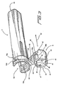
- Fig. 3 is a perspective view of the needle protection housing and the collar to which it is connected for the needle protection assembly of the instant invention
- Fig. 4 is another view of the needle protection housing and the collar to which it is attached;
- Fig. 5 is yet another view of the needle protection housing and the collar to which it is attached;
- Fig. 6 is a plan view of the needle protection housing and the collar to which it is attached;
- Fig. 7 is a perspective view of the needle sheath of the needle protection assembly of the instant invention.
- Fig. 8 is a view to the interior of the needle sheath of Fig. 7 ;
- Fig. 9 is semi-cut away view of the fully assembled needle protection assembly of the instant invention.
- Fig. 10 is a cross-sectional view of the instant inventive needle protection assembly.
- Fig. 11 is a perspective view of the fully assembled needle protection assembly of the instant invention.
- the needle protection assembly is shown to include a needle hub 2 and a needle protection housing 4 to which is connected a collar 6.
- the needle protection assembly further includes a needle sheath 8 that is to be removably connected to collar 6 for covering needle 10 prior to the latter's use.
- needle hub 2 is shown to have a proximal portion 12 and a distal portion 14.
- the needle hub 2 is cylindrical in shape with proximal portion 12 having a greater circumference than distal portion 14.
- a luer adaptable fitting 16 for mating with luer lock type end of a syringe.
- Luer end 16 is ISO standard so that needle hub 2 is matable with a conventional luer of a syringe, or other similarly luered devices.
- proximal end 12 of needle hub 2 are a plurality of flanges, divided into a first set of upper flanges 18 and a second set of lower flanges 20.
- Flanges 20a and 20b extend orthogonally from the body of needle hub 2, and act as a retainer base for collar 6.
- the upper or the first set of flanges 18 also extend transversely from the body of needle hub 2 at the fore section of proximal portion 12.
- each of the first flanges 18a-18d are beveled, or chamfered as shown, so as to allow collar 6 to be more readily press-fitted past flanges 18a-18d onto the space 24 defined by flanges 18 and 20.
- the back surfaces 26a-26d of flanges 18a-18d, respectively, are flat, so that once collar 6 is fitted into space 24, it no longer could be removed therefrom.
- a groove 28 is formed adjacent to the underside of back surfaces 26a-26d of flanges 18a-18d, respectively, to effect a right angled relationship between surfaces 26 and the body of needle hub 2 to minimize the play between collar 6 and the retention flanges.
- Element 30 is a remnant from the injection molding process of needle hub 2, as needle hub 2 may be made of ABS plastic, which is a styrene type plastic.
- Distal portion 14 of needle hub 2 may also be referred to as the neck of the needle hub.
- a plurality of arms or stubs shown as three exemplar sets, extend transversely from distal portion 14 of needle hub 2.
- a first set of arms 32a-32d are formed at the proximal end of distal portion 14.
- a second set of arms 34a-34c are formed at the mid section of distal portion 14.
- the first and second sets of arms 34 and 32 are in alignment with each other so that a number of v-shaped slots 36a, 36b and 36c are formed by aligned arms 32 and 34.
- These v-shaped slots or channels are to be fitted with a spline integral of needle sheath 8 for rotation purposes.
- Additional arms or stubs 38a and 38b are provided at the distal end of distal portion 14 of the needle hub 2. Arms 38a and 38b are used as stops for coacting against an integral spline in housing 4. The orientation of the respective sets of arms 32, 34 and 38, relative to distal portion 14 of needle hub 2, are such that slots 36a-36c are oriented not to interfere with arms 38a and 38b.
- a needle such as 10 shown in Fig.1 , extends from distal end 40 of needle hub 2. As shown in Fig. 1 , needle hub 2 has a longitudinal axis 13.
- needle protection housing. 4 and collar 6 to which it is connected are hereby described.
- collar 6 is cylindrical in shape and has a proximal portion or end 42 and a distal portion or end 44.
- Distal end 44 of collar 6 is shown to have a plurality of catch fingers or retainers 46 and two slots or channels 48 to provide additional flexibility thereat for facilitating the insertion and removal of needle sheath 8.
- a plurality of protrusions 50a-50d are provided at proximal end 42 of collar 6. Protrusions 50a-50d are dimensioned such that they would fit into space 24 ( Fig.
- collar 6 is fitted to needle hub 2 via the direction shown by directional arrow 52 in Fig. 3 and directional arrow 54 in Fig. 2 .
- collar 6 is readily press-fitted over flanges 18 to settle into space 24, as its forward movement is stopped by retainer flanges 20a and 20b.
- collar 6 remains movably coupled to proximal portion 12 of needle hub 2.
- a portion 56 of collar 6 ( Fig. 3 ), along with a not shown portion on the other side of collar 6, are thinned, so that extra flexibility is provided at distal end 42 of collar 6 to enhance the press or snap fitting of collar 6 over retainer flanges 18 for retention within space 24 of needle hub 2.
- Hinge 58 is a newly designed living hinge that has a widened bent area 60, as well as groove 62 to enable needle housing 4 to be pivoted a great number of times relative to collar 6 without breaking off.
- Needle protection housing 4 has an open proximal end 64 and a closed end 66.
- Housing 4 is cylindrical in shape and has an opening 68 ( Figs. 4 and 6 ) through which needle 10 passes, when housing 4 is pivoted toward collar 6 for covering needle 10, after needle sheath 8 has been removed from collar 6.
- Opening or channel 68 is formed by two lips or flaps 70 and 72 each of which extends longitudinally along substantially the entire length of housing 4. Lip 40 is shown to overlap lip 72. The overlapping is such that the combination of lips 70 and 72 provides a trap door for needle 10. Once needle 10 enters fully into housing 4, after passing lips 70 and 72, it is prevented from coming out of housing 4.
- Opening 68 due to its formation by lips 70 and 72, is off centered to one side of housing 4.
- each of lips 70 and 72 is angled, by a series of complex angles, toward the interior of housing 4. The respective angles of each of the lips would therefore vary along the length of the housing for guiding needle 10 into housing 4, along the path as shown by dotted line 74, into the interior of housing 4 via opening 68.
- the respective progressively angled surfaces of lips 70 and 72 are designated 71 and 73, respectively ( Fig. 4 ).
- the angled entry of needle 10 into housing 4 is effected in a smooth manner to substantially eliminate the possibility that contaminated fluid that remains on the needle may be flickered or splattered, when the needle comes into contact with housing 4.
- a spline 76 is integrated to and extends from the back inner surface of needle protection housing 4. After needle 10 has fully entered into housing 4, spline 76 would coact against at least one of the arms 38a and 38b, so that if needle housing 4 is turned, needle hub 2 likewise is rotated due to the rotational motion imparted to needle hub 2 by the coaction of spline 76 and arms 38.
- the set of arms or stubs 38 may have a number of arms, such as for example the same number as arms 32 and 34.
- arms 38 act as a catch for integral spline 76 so that needle hub 2 is rotated in synchronization with the turning of needle protection housing 4.
- a lock mechanism is provided at the proximal end 64 of needle housing 4 and the exterior surface of collar 6. This ensures that once needle housing 4 is pivoted to the position along longitudinal axis 13, it will remain in alignment thereat.
- This lock mechanism is shown in Figs. 3-6 as two apertures 78a and 78b at the base of needle housing 4, and two corresponding one-way catch members 80a and 80b at collar 6.
- aperture 78a and 78b will snap fit over the one-way catch members 80a and 80b, respectively.
- Needle sheath 8 is described herein with reference to Figs. 7 and 8 .
- needle sheath 8 has an open base 84 at its proximal end and is closed at its distal end.
- Sheath 8 may be made of polypropylene that is clear, or glass so as to enable the user to visually view needle 10, when needle sheath 8 is removably coupled to collar 8.
- a rim or groove 86 is formed at sheath 8 between base 84 and a circumferential shoulder 88.
- a number of finger grip extensions 90 formed along the longitudinal exterior surface of needle sheath 8 enable the user to readily grip needle sheath 8.
- the open end of needle sheath 8, i.e., base 84 first makes contact with the internal fingers 46 of collar 6. Since the respective top surfaces 47 of fingers 46 are beveled and slots or channels 48 are provided at distal end 44 of collar 6, needle sheath 8 is readily inserted into the distal end 44 of collar 6, with fingers 46 of collar 6 grasping rim 86 of needle sheath 8. Circumferential shoulder 88 of sheath 8 is designed to have a dimension that enables it to seat onto edge 45 of the distal end 44 of collar 6. As a consequence, needle, sheath 8 is coupled to collar 6, and more particularly to distal end 44 of collar 6, with fingers 46 gripping base 84 at rim 86.
- the coupling of needle sheath 8 to collar 6 is such that sheath 8 is prevented from separating accidentally from collar 6, and yet sheath 8 is readily removable from collar 6, if a predetermined force is applied in the direction opposite to that shown by directional arrow 92.
- Figs. 9 and 10 are cross sectional views showing needle sheath 8 removably coupled to collar 6, and collar 6 fitting to needle hub 2.
- Fig. 11 is a perspective view illustrating the needle protection assembly fully assembled and ready for shipment.
- a user removes needle sheath 8 by applying a predetermined, or greater, force in the direction opposite to that of the directional arrow 92 ( Fig. 1 ). Once exposed, needle 10 may be used.
- needle protection housing 4 is pivoted to the direction of longitudinal axis 13 so that the contaminated needle enters into housing 4 and is trapped inside housing 4 by the trap door formed by the two lips.
- housing 4 is fixedly retained to collar 6 by the mating of apertures 78 to one-way catch members 80.
- housing 4 is rotated to cause spline 76 extending from the back inner surface of housing 4 to act against at least one of the arms extending from the needle hub 2.
Landscapes
- Health & Medical Sciences (AREA)
- Engineering & Computer Science (AREA)
- Heart & Thoracic Surgery (AREA)
- Vascular Medicine (AREA)
- Anesthesiology (AREA)
- Biomedical Technology (AREA)
- Environmental & Geological Engineering (AREA)
- Hematology (AREA)
- Life Sciences & Earth Sciences (AREA)
- Animal Behavior & Ethology (AREA)
- General Health & Medical Sciences (AREA)
- Public Health (AREA)
- Veterinary Medicine (AREA)
- Infusion, Injection, And Reservoir Apparatuses (AREA)
Claims (25)
- Vorrichtung, die Folgendes umfasst:einen Nadelaufsatz (2) mit einer Längsachse und einer Nadel (10), die sich von einem seiner Enden erstreckt;eine Manschette (6), die um den Nadelaufsatz (2) herum drehmontiert wird; undeine Nadelhülse (8) zum Abdecken der Nadel, die sich von dem Nadelaufsatz (2) erstreckt, vor deren Verwendung, dadurch gekennzeichnet, dass die Hülse (8) entfernbar an der Manschette (6) angebracht ist und mindestens einen Innenkeil (92a, 92b) aufweist, der mit einer Sperre an dem Nadelaufsatz (2) zusammenwirkt, so dass der Nadelaufsatz (2) durch die Hülse (8) drehbar ist.
- Vorrichtung nach Anspruch 1, die weiterhin Folgendes umfasst:ein Gehäuse (4), das mit der Manschette (6) verbunden ist und in eine Position schwenkbar ist, die im Wesentlichen in einer Linie entlang der Längsachse des Nadelaufsatzes ist, zum Abdecken der Nadel (10), nachdem die Nadelhülse (8) von der Manschette entfernt wurde.
- Vorrichtung nach Anspruch 2, die weiterhin eine Spritze mit einem Luer-Ende umfasst, wobei der Nadelaufsatz (2) mit der Spritze am anderen seiner Enden (16) zusammenpasst, wobei das Gehäuse (4) mindestens einen Innenkeil (76) hat, der mit mindestens einer Sperre (38a, 38b) an dem Aufsatz (2) zusammenwirken kann, um die Trennung des Nadelaufsatzes (2) von der Spritze zu erleichtern, nachdem das Gehäuse (4) in die Position geschwenkt wurde, um die Nadel (10) abzudecken.
- Vorrichtung nach Anspruch 1, wobei der Nadelaufsatz (2) mindestens einen Schlitz (36a - 36d) hat, um die Sperre zu bilden, mit der der Keil (92a, 92b) der Hülse zusammenwirkt, wenn die Hülse (8) an der Manschette (6) angebracht ist.
- Vorrichtung nach Anspruch 2, wobei das Gehäuse (4) eine Längsöffnung (68) hat, die von einer ersten und einer zweiten Lippe (70, 72) gebildet wird, die sich jeweils entlang im Wesentlichen der Länge des Gehäuses erstrecken, wobei die erste Lippe (70) mit einem Teil der zweiten Lippe (72) überlappt, wobei die Öffnung (68) von der Längsachse seitlich versetzt ist, wobei jede der Lippen (70, 72) in Richtung des Inneren des Gehäuses abgewinkelt ist, wobei die jeweiligen Winkel der Lippen entlang der Länge des Gehäuses unterschiedlich sind, um eine Führung für die Nadel zu erwirken, damit diese leichtgängig in einem Winkel durch die Öffnung (68) in das Gehäuse eintritt, wenn das Gehäuse (4) geschwenkt wird, um die Nadel abzudecken, wobei die Nadel nicht von dem Gehäuse entfernbar ist, sobald die Nadel vollständig in das Gehäuse eintritt.
- Vorrichtung nach Anspruch 1, wobei der Nadelaufsatz (2) einen proximalen Teil (12) und einen distalen Teil (14), mindestens einen und weitere Flansche (18a - 18d; 20a, 20b), die sich quer von dem proximalen Teil (12) erstrecken, wobei der eine und die weiteren Flansche entlang der Länge des proximalen Teils voneinander beabstandet sind, eine Reihe Arme (32a - 32d, 34a - 34d) umfasst, die sich quer von dem distalen Teil (14) des Nadelaufsatzes (2) zum Bilden mindestens eines Schlitzes (36a - 36c) zum Zusammenwirken mit einem Keil (92a, 92b), der ein integraler Teil der Nadelhülse (8) ist, erstrecken, und einer Sperre (38a, 38b) zum Zusammenwirken mit einem Keil (72), der ein integraler Teil eines Gehäuses (4) ist, das von der Manschette (6) schwenkbar ist, wenn das Gehäuse (4) geschwenkt wird, um die Nadel (10) abzudecken.
- Vorrichtung nach Anspruch 6, wobei der proximale Teil (12) des Nadelaufsatzes (2) ein Luer-Ende (16) zum Zusammenpassen mit einer Spritze hat und der distale Teil (14) des Nadelaufsatzes (2) einen Hals (40) hat, an dem sich die Nadel angebracht erstreckt.
- Vorrichtung nach Anspruch 1, wobei die Manschette (6) an einem proximalen Teil ihrer Innenfläche mindestens einen Vorsprung (50a - 50d) zum Passen in einen Raum (24) umfasst, der von beabstandeten Flanschen (22a - 22c; 20a, 20b) gebildet wird, die sich quer von einem proximalen Teil (12) des Nadelaufsatzes (2) erstrecken, wobei die Manschette (6) um den Nadelaufsatz (2) herum drehbar ist, wenn der Vorsprung (50a - 50d) in den Raum (24) eingepasst ist, wobei die Manschette (6) weiterhin an einem distalen Teil ihrer Innenfläche mindestens einen Finger (46) umfasst, um in einen Rand (86) am offenen Ende (84) der Nadelhülse (8) einzugreifen, so dass, sobald der Eingriff hergestellt wurde, die Nadelhülse (8) entfernbar an der Manschette (6) angebracht ist.
- Vorrichtung nach Anspruch 2, wobei die Manschette (6) an ihrer Außenfläche einen ersten Arretiermechanismus (80a, 80b) ausgebildet hat und wobei das Gehäuse (4) an seinem proximalen Ende einen zweiten Arretiermechanismus (78a, 78b) ausgebildet hat, wobei der erste und der zweite Arretiermechanismus zusammenwirken, um das Gehäuse (4) fixiert an der Manschette (6) zu halten, sobald das Gehäuse (4) in die Position geschwenkt wird, um die Nadel (10) abzudecken.
- Vorrichtung nach Anspruch 9, wobei der erste Arretiermechanismus mindestens ein Einwegsperrenelement (80a, 80b) umfasst, das sich von der Außenfläche der Manschette (6) erstreckt, und der zweite Arretiermechanismus mindestens einen entsprechenden Durchlass (78a, 78b) an dem Gehäuse (4) umfasst, wobei das Einwegsperrenelement zum fixierten Halten des Gehäuses an der Manschette, wenn das Gehäuse geschwenkt wird, um die Nadel abzudecken, zusammenpassend mit dem Durchlass gekuppelt wird.
- Vorrichtung nach Anspruch 1, wobei der Nadelaufsatz einen proximalen Teil (12) und einen distalen Teil (14), eine erste Vielzahl (22a - 22d) und eine zweite Vielzahl (20a, 20b) von Flanschen, die sich quer umlaufend von dem proximalen Teil (12) erstrecken, wobei die erste und die zweite Vielzahl von Flanschen (22a - 22d; 20a, 20b) voneinander beabstandet sind, um einen umlaufenden Raum (24) an dem proximalen Teil (12) des Nadelaufsatzes (2) zu definieren, Sätze von Armen (34a - 34d; 32a - 32d), die sich quer von dem distalen Teil (14) des Nadelaufsatzes zum Bilden mindestens eines Schlitzes (36a - 36c) zum Zusammenwirken mit der Nadelhülse (8) erstrecken, die mit einer Manschette (6) gekuppelt ist, die zum Abdecken einer Nadel (10), die sich von dem Nadelaufsatz erstreckt, vor der Verwendung drehbar um den Nadelaufsatz (2) herum montiert ist, und mindestens eine Sperre (38a, 38b) zum Zusammenwirken mit einem Gehäuse (4) umfasst, das von der Manschette (6) schwenkbar ist, um die Nadel nach dem Entfernen der Hülse (8) von der Manschette (6) abzudecken.
- Vorrichtung nach Anspruch 11, wobei die Seite jedes Flansches (22a - 22c) einer der ersten und der zweiten Vielzahl von Flanschen (18a - 18c), gegen die die Manschette (6) zum Montieren des Nadelaufsatzes (2) eingepresst ist, abgeschrägt ist, um das Einpassen der Manschette (6) an dem Nadelaufsatz zu vereinfachen, wobei die Manschette (6) an, jedoch drehbar um den Raum (24) herum gehalten wird, der von der ersten und der zweiten Vielzahl von Flanschen (18a - 18c; 20a, 20b) definiert wird, sobald sie an den abgeschrägten Flanschen (22a - 22c) vorbei eingepresst ist.
- Vorrichtung nach Anspruch 11, wobei der Nadelaufsatz (2) an seinem proximalen Teil (12) ein Luer-Ende (16) zum Zusammenpassen mit einer Spritze umfasst.
- Vorrichtung nach Anspruch 1, wobei die Manschette (6) an der Innenfläche ihres distalen Teils (44) mindestens eine Halteeinrichtung (47) zum entfernbaren Halten der Nadelhülse (8) hat, die zum Abdecken der Nadel vor deren Verwendung an der Manschette (6) angebracht ist, wobei die Hülse (8) und der Nadelaufsatz (2) miteinander zusammenwirken, so dass der Nadelaufsatz (2) synchron mit der Hülse (8) drehbar ist, wenn die Hülse (8) umgedreht wird, wobei ein Gehäuse (4) eine seitlich versetzte Längsöffnung (68) hat, die mit der Manschette (6) verbunden ist und zum Abdecken der Nadel (10) nach dem Entfernen der Nadelhülse (8) von der Manschette (6) in eine Position schwenkbar ist, die im Wesentlichen in einer Linie entlang der Längsachse ist, wobei das Gehäuse (4) mit dem Nadelaufsatz (2) zusammenwirkt, so dass der Nadelaufsatz (2) durch das Gehäuse (4) drehbar ist, nachdem das Gehäuse in die Position geschwenkt wurde, um die Nadel (10) abzudecken.
- Vorrichtung nach Anspruch 14, wobei der Nadelaufsatz (2) Flanschmittel (18a - 18c; 20a, 20b), die an dem proximalen Teil (12) vorgesehen sind, zum Halten der Manschette (6) und einen Schlitz (36a - 36c), der an dem distalen Teil (14) vorgesehen ist, umfasst, wobei die Nadelhülse (8) mindestens einen Innenkeil (92a, 92b) hat, der in den Schlitz (36a - 36c) passt, so dass der Nadelaufsatz (2) mittels eines Gewindes durch Drehen der Nadelhülse (8) mit einem Luer-Anschluss einer Spritze gekuppelt werden kann.
- Vorrichtung nach Anspruch 15, wobei der Nadelaufsatz (2) weiterhin eine Sperre (38a, 38b), die an dem distalen Teil (14) vorgesehen ist, umfasst, wobei das Gehäuse (4) einen Innenkeil (76) hat, der gegen die Sperre (38a, 38b) zusammenwirkt, nachdem das Gehäuse (4) geschwenkt wurde, um die Nadel (10) abzudecken, so dass der Nadelaufsatz (2) synchron mit der Drehung des Gehäuses (4) gedreht wird, wobei der Nadelaufsatz (2) durch Drehen des Gehäuses (4) von einem Luer-Ende einer Spritze, mit dem er gekuppelt ist, entfernbar ist.
- Vorrichtung nach Anspruch 15, wobei das Flanschmittel zwei Sätze von beabstandeten Flanschen (18a - 18c; 20a, 20b) am proximalen Teil (12) des Nadelaufsatzes (2) umfasst und wobei die Manschette (6) an der Innenfläche ihres proximalen Teils eine Vielzahl von Vorsprüngen (50a - 50d) hat, wobei die Vorsprünge (50a - 50d) zwischen die beabstandeten Flansche (18a - 18c; 20a, 20b) passen, wenn die Manschette (6) um den Nadelaufsatz (2) herum gepasst wird, wobei die Manschette (6) um den Nadelaufsatz (2) herum drehbar ist.
- Vorrichtung nach Anspruch 14, wobei die Öffnung (68) entlang des Gehäuses (4) von einer ersten und einer zweiten Lippe (70, 72) gebildet wird, die sich jeweils entlang im Wesentlichen der Länge des Gehäuses (4) erstrecken, wobei die erste Lippe (70) mit einem Teil der zweiten Lippe (72) überlappt, wobei die Öffnung (68) seitlich versetzt ist, wobei jede der Lippen (70, 72) in Richtung des Inneren des Gehäuses (4) abgewinkelt ist, wobei die jeweiligen Winkel der Lippen entlang der Länge des Gehäuses unterschiedlich sind, wobei, wenn das Gehäuse (4) in Bezug auf die Manschette schwenkbewegt wird, um die Nadel (10) abzudecken, die Nadel von den Lippen geführt wird, um leichtgängig in das Gehäuse (4) einzutreten, wobei die Nadel nicht von dem Gehäuse entfernbar ist, sobald die Nadel vollständig in das Gehäuse eingetreten ist.
- Vorrichtung nach Anspruch 14, wobei die Manschette (6) an ihrer Außenfläche mindestens zwei Sperrenelemente (80a, 80b) ausgebildet hat und wobei das Gehäuse (4) an seinem proximalen Ende mindestens zwei entsprechende Durchlässe (78a, 78b) ausgebildet hat, wobei die Sperrenelemente (80a, 80b) zusammenpassend mit den Durchlässen (78a, 78b) gekuppelt werden, um das Gehäuse (4) fixiert an der Manschette (6) zu halten, wenn das Gehäuse (4) zu der Längsachse geschwenkt wird, um die Nadel (10) abzudecken.
- Verfahren zur Herstellung einer medizinischen Nadelbaugruppe, das die folgenden Schritte umfasst:a) Bereitstellen eines Nadelaufsatzes (2) mit einem proximalen Teil (12) und einem distalen Teil (14);b) Ausziehen einer Nadel (10) von dem distalen Teil des Aufsatzes (2);c) Drehmontieren einer Manschette (6) um den Nadelaufsatz (2) herum, wobei die Manschette (6) an der Innenfläche ihres distalen Endes (44) mindestens eine Halteeinrichtung (46) umfasst; und gekennzeichnet durchd) Anbringen einer Nadelhülse (8) an der Manschette (6) zum Abdecken der Nadel (10) vor deren Verwendung, wobei die Nadelhülse (8) von der Halteeinrichtung gehalten wird, wobei die Hülse (8) mindestens einen Innenkeil (92a, 92b) aufweist, der mit einer Sperre an dem Nadelaufsatz (2) zusammenwirkt, so dass der Nadelaufsatz (2) durch die Hülse (8) drehbar ist.
- Verfahren nach Anspruch 20, das weiterhin die folgenden Schritte umfasst:Verbinden eines Gehäuses (4) mit der Manschette (6) undAusführen einer seitlich versetzten Längsöffnung (68) im Wesentlichen entlang der Länge des Gehäuses (4), wobei das Gehäuse in eine Position schwenkbar ist, die im Wesentlichen in einer Linie entlang der Längsachse des Nadelaufsatzes (2) ist, zum Abdecken der Nadel (10) nach der Entfernung der Nadelhülse (8) von der Manschette (6).
- Verfahren nach Anspruch 20, wobei der Schritt a die folgenden Schritte umfasst:Integrieren mindestens eines und weiterer Flansche (18a - 18c; 20a, 20b) quer zu dem proximalen Teil (12) des Nadelaufsatzes (2);Anordnen des einen und der weiteren Flansche (18a - 18c; 20a, 20b) beabstandet voneinander entlang der Länge des proximalen Teils;Abschrägen der Seite (22a - 22c) jedes der Flansche (18a - 18c), gegen die die Manschette (6) eingepresst ist, zum Vereinfachen des Einpassens der Manschette (6) auf dem Nadelaufsatz (2) undAusziehen einer Reihe Arme (34a - 34d; 32a - 32d) quer von dem distalen Teil (14) des Nadelaufsatzes (2) zum Bilden mindestens eines Schlitzes (36a - 36c) zum Zusammenwirken mit einem integralen Keil (92a, 92b) des Nadelaufsatzes (8) und einer Sperre (38a, 38b) zum Zusammenwirken mit einem integralen Keil (76) eines Gehäuses (4), das von der Manschette (6) schwenkbar ist, um die Nadel (10) abzudecken.
- Verfahren nach Anspruch 20, das weiterhin die folgenden Schritte umfasst:Bilden einer Vielzahl von Vorsprüngen (50a - 50d) an der Innenfläche eines proximalen Teils (42) der Manschette (6) undBilden einer Vielzahl von Halteeinrichtungen (46) an der Innenfläche eines distalen Teils (44) der Manschette (6);wobei der Schritt c den folgenden Schritt umfasst:Einpressen der Manschette (6) an den Nadelaufsatz (2) durch Einpassen der Vorsprünge (50a - 50d) in einen Raum (24), der von beabstandeten Flanschen (18a - 18c; 20a, 20b) definiert wird, die sich quer von einem proximalen Teil (12) des Nadelaufsatzes (2) erstrecken, wobei die Manschette (6) um den Nadelaufsatz (2) herum drehbar ist, wenn die Vorsprünge (50a - 50d) in den Raum (24) eingepasst sind; undwobei der Schritt d den folgenden Schritt umfasst:Eingreifenlassen eines Rands (86) am offenen Ende (84) der Nadelhülse (8) mit den Halteeinrichtungen (46) der Manschette (6) zum entfernbaren Kuppeln der Nadelhülse (8) mit der Manschette (6), um die Nadel (10) vor deren Verwendung abzudecken.
- Verfahren nach Anspruch 21, das weiterhin die folgenden Schritte umfasst:Ausbilden mindestens eines Sperrenelements (80a, 80b) an der Außenfläche der Manschette (6) undAusbilden mindestens eines entsprechenden Durchlasses (78a, 78b) an einem proximalen Ende des Gehäuses (4);wobei das Sperrenelement (80a, 80b) sich zusammenpassend mit dem Durchlass (78a, 78b) kuppelt, um das Gehäuse (4) fixiert an der Manschette (6) zu halten, wenn das Gehäuse zu der Längsachse geschwenkt wird, um die Nadel (10) abzudecken.
- Verfahren nach Anspruch 21, wobei der Ausführungsschritt weiterhin die folgenden Schritte umfasst:Ausführen einer ersten und einer zweiten Lippe (70, 72) entlang im Wesentlichen der Länge des Gehäuses zum Ausbilden der Längsöffnung (68);Überlappenlassen eines Teils der ersten Lippe (70) über die zweite Lippe (72), um die seitlich versetzte Öffnung (68) auszuführen; undAbwinkeln jeder der Lippen (70, 72) in Richtung des Inneren des Gehäuses (4), wobei die jeweiligen Winkel der Lippen entlang der Länge des Gehäuses unterschiedlich sind, um zu ermöglichen, dass die Lippen (70, 72) die Nadel (10) leichtgängig durch die Öffnung (68) in das Gehäuse (4) führen, wenn das Gehäuse geschwenkt wird, um die Nadel abzudecken, wobei die Nadel nicht von dem Gehäuse entfernbar ist, sobald die Nadel vollständig in das Gehäuse eintritt.
Applications Claiming Priority (2)
| Application Number | Priority Date | Filing Date | Title |
|---|---|---|---|
| US10/649,837 US7201736B2 (en) | 2003-08-28 | 2003-08-28 | Needle protection assembly |
| PCT/US2004/026866 WO2005023329A2 (en) | 2003-08-28 | 2004-08-19 | Needle protection assembly |
Publications (3)
| Publication Number | Publication Date |
|---|---|
| EP1663341A2 EP1663341A2 (de) | 2006-06-07 |
| EP1663341A4 EP1663341A4 (de) | 2010-06-09 |
| EP1663341B1 true EP1663341B1 (de) | 2013-01-16 |
Family
ID=34217024
Family Applications (1)
| Application Number | Title | Priority Date | Filing Date |
|---|---|---|---|
| EP04781532A Expired - Lifetime EP1663341B1 (de) | 2003-08-28 | 2004-08-19 | Nadelschutzanordnung |
Country Status (6)
| Country | Link |
|---|---|
| US (2) | US7201736B2 (de) |
| EP (1) | EP1663341B1 (de) |
| JP (1) | JP4846580B2 (de) |
| CA (2) | CA2535773C (de) |
| MX (1) | MXPA06002094A (de) |
| WO (1) | WO2005023329A2 (de) |
Families Citing this family (51)
| Publication number | Priority date | Publication date | Assignee | Title |
|---|---|---|---|---|
| US7341576B2 (en) * | 2002-03-29 | 2008-03-11 | Bioform Medical, Inc. | Medical delivery/extraction system |
| US11083841B2 (en) | 2002-08-09 | 2021-08-10 | Fenwal, Inc. | Needle protector, needle assembly and fluid processing set including the same |
| US7250038B2 (en) * | 2003-09-09 | 2007-07-31 | Smiths Medical Asd, Inc. | Fixed needle syringe with protective needle housing |
| US20060084917A1 (en) * | 2004-07-16 | 2006-04-20 | Vincent Chen | Retractable syringe |
| US8016796B2 (en) * | 2005-05-27 | 2011-09-13 | Smiths Medical Asd, Inc. | Safety needle device with snap feature and method of making same |
| GB0608838D0 (en) * | 2006-05-04 | 2006-06-14 | Novartis Ag | Organic compounds |
| US8083098B1 (en) | 2007-02-22 | 2011-12-27 | Michael Schaffer | Storage and dispensing system for needle-shields |
| JP2010533020A (ja) | 2007-07-12 | 2010-10-21 | スター・シリンジ・リミテッド | 針刺し防止装置 |
| USD645907S1 (en) * | 2008-02-08 | 2011-09-27 | Sandel Medical Industries Llc | Hood for a surgical instrument |
| WO2010066704A1 (en) * | 2008-12-12 | 2010-06-17 | Sanofi-Aventis Deutschland Gmbh | Protection assembly |
| JP5019138B2 (ja) * | 2009-10-21 | 2012-09-05 | 株式会社デンソー | タンパープルーフ成形品、および、これを用いたアクセル装置 |
| USD625805S1 (en) * | 2009-10-27 | 2010-10-19 | Robert Hereford | Needle guide |
| US20110144614A1 (en) * | 2009-12-11 | 2011-06-16 | Robert Hereford | Syringe guide and associated methods |
| EP2378342A1 (de) * | 2010-04-15 | 2011-10-19 | Mmi Ag | Mikromanipulationssystem mit Schutzvorrichtung für Kapillaren |
| US10639430B2 (en) | 2010-11-22 | 2020-05-05 | B. Braun Melsungen Ag | Hinged shield assemblies and related methods |
| MX336571B (es) | 2011-01-24 | 2016-01-25 | Elcam Medical Agricultural Cooperative Ass Ltd | Inyector. |
| EP3603707B1 (de) * | 2011-02-14 | 2023-06-21 | Terumo Kabushiki Kaisha | Sicherheitsnadelanordnung |
| CN202724375U (zh) * | 2011-05-06 | 2013-02-13 | 上海萌黎国际贸易有限公司 | 安全针组件 |
| US20120323216A1 (en) * | 2011-06-16 | 2012-12-20 | Koh Lawrence R | Needleshield assembly |
| WO2013034631A1 (en) * | 2011-09-08 | 2013-03-14 | Sanofi-Aventis Deutschland Gmbh | Securing means for a drug delivery device |
| CN103405831B (zh) * | 2012-10-30 | 2015-07-08 | 张林锋 | 一种安全注射针 |
| GB2512913A (en) * | 2013-04-11 | 2014-10-15 | Owen Mumford Ltd | Needle tip storage and removal device and methods of manufacture thereof |
| CN104174098A (zh) * | 2013-05-20 | 2014-12-03 | 上海康德莱企业发展集团股份有限公司 | 一种安全壳式注射器 |
| CN103432657B (zh) * | 2013-09-13 | 2015-12-09 | 扬州美德莱医疗用品有限公司 | 一种安全注射针 |
| CN105979991B (zh) * | 2013-12-05 | 2020-03-03 | 梅捷医药有限公司 | 安全夹具 |
| EP2902063A1 (de) * | 2014-02-04 | 2015-08-05 | Sanofi-Aventis Deutschland GmbH | Hüllenentfernungsmechanismus |
| KR102285178B1 (ko) | 2014-03-31 | 2021-08-02 | 니프로 가부시키가이샤 | 시린지, 및 주사 바늘용 안전 장치 |
| US9867951B2 (en) | 2014-04-08 | 2018-01-16 | B. Braun Melsungen Ag | Hinged cap needle assemblies and related methods |
| US10029049B2 (en) | 2015-03-19 | 2018-07-24 | B. Braun Melsungen Ag | Hinged shield assemblies and related methods |
| JP6636503B2 (ja) * | 2015-03-27 | 2020-01-29 | テルモ株式会社 | 注射針組立体および薬剤注射装置 |
| US11918249B2 (en) | 2015-07-15 | 2024-03-05 | Axcess Instruments IP Holding Company | Access device with anchoring body and modular inserts and support structure for supporting accessories used in minimally invasive surgical procedures |
| US10687847B2 (en) * | 2015-07-15 | 2020-06-23 | Axcess Instruments Inc. | Access device having modular inserts and supporting accessories used in minimally invasive surgical procedures |
| WO2017129968A2 (en) * | 2016-01-25 | 2017-08-03 | Star Syringe Limited | Needlestick prevention device |
| KR102487355B1 (ko) | 2016-04-25 | 2023-01-11 | 코스카 패밀리 리미티드 | 의료 전달 시스템 |
| KR20190116262A (ko) * | 2016-12-14 | 2019-10-14 | 스타 시린지 리미티드 | 주사 바늘 상해 방지 장치 |
| US20180272074A1 (en) * | 2017-03-24 | 2018-09-27 | Te-Peng HUANG | Needle protector and syringe having the same |
| KR102639913B1 (ko) | 2017-11-17 | 2024-02-23 | 코스카 패밀리 리미티드 | 유체 전달 매니폴드를 위한 시스템 및 방법 |
| UA131182U (uk) * | 2018-06-15 | 2019-01-10 | Микола Іванович Гуменюк | Знімна ін'єкційна голка із захистом від випадкового уколу |
| US12544511B2 (en) | 2018-06-20 | 2026-02-10 | Koska Family Limited | Systems and methods for pre-filled dual-chamber medical agent delivery |
| WO2020241708A1 (ja) * | 2019-05-27 | 2020-12-03 | ニプロ株式会社 | プロテクタ付穿刺針 |
| DE202019103876U1 (de) * | 2019-07-15 | 2019-07-24 | FMW Technology Consulting GmbH | Schutzvorrichtung für das Nadelrohr einer Spritze |
| USD1052082S1 (en) | 2020-06-01 | 2024-11-19 | Koska Family Limited | Sealed fluid container |
| WO2022025969A1 (en) * | 2020-07-28 | 2022-02-03 | Neogen Corporation | Hypodermic interface assembly |
| US11938309B2 (en) | 2020-07-28 | 2024-03-26 | Neogen Corporation | Hypodermic interface assembly |
| WO2023018840A1 (en) * | 2021-08-10 | 2023-02-16 | Koska Family Limited | Pre-filled medical delivery assembly with a needle shield |
| USD992110S1 (en) | 2021-08-10 | 2023-07-11 | Koska Family Limited | Sealed fluid container |
| CN113855553B (zh) * | 2021-11-03 | 2024-03-26 | 王小勇 | 一种用于中医针灸的辅助定位设备 |
| WO2023088345A1 (zh) * | 2021-11-19 | 2023-05-25 | 上海倍莱弗科技有限公司 | 一种密封保护型针筒装置 |
| DE102022111083A1 (de) * | 2022-05-05 | 2023-11-09 | Stephan Fischer | Schutzvorrichtung für ein Nadelrohr einer Spritze |
| CN115054781B (zh) * | 2022-05-26 | 2024-05-31 | 扬州美德莱医疗用品股份有限公司 | 一种安全针罩和针座的连接结构 |
| USD1117739S1 (en) | 2022-10-18 | 2026-03-10 | Neogen Corporation | Hypodermic interface assembly |
Family Cites Families (35)
| Publication number | Priority date | Publication date | Assignee | Title |
|---|---|---|---|---|
| US4664259A (en) | 1985-05-13 | 1987-05-12 | Robert Landis | Needle container and method for preventing accidental contact with a needle |
| US4931048A (en) * | 1986-04-07 | 1990-06-05 | Icu Medical, Inc. | Medical device |
| US5037401A (en) | 1990-04-20 | 1991-08-06 | Decamp Dennis M | Hypodermic needle cannula guard |
| US5171303A (en) | 1990-04-20 | 1992-12-15 | Decamp Dennis M | Hypodermic needle cannula guard |
| US5188611A (en) | 1990-05-31 | 1993-02-23 | Orgain Peter A | Safety sheath for needles, sharp instruments and tools |
| US4982842A (en) | 1990-06-04 | 1991-01-08 | Concord/Portex | Safety needle container |
| US5139489A (en) | 1991-01-07 | 1992-08-18 | Smiths Industries Medical Systems, Inc. | Needle protection device |
| US5232454A (en) | 1990-08-01 | 1993-08-03 | Smiths Industries Medical Systems, Inc. | Safety needle container |
| US5277311A (en) | 1991-12-20 | 1994-01-11 | Smiths Industries Medical Systems, Inc. | Needle assembly holder with rotatable safety sheath member and method of effecting proper alignment of a cannula using such needle assembly holder |
| USRE37110E1 (en) | 1992-05-18 | 2001-03-27 | William H. Hollister | Locking safety needle protection system |
| DK0649382T3 (da) | 1992-05-18 | 2001-11-12 | Sims Portex Inc | Sikkerhedsbeskyttelsesindretning til nåle |
| US5993426A (en) * | 1993-04-16 | 1999-11-30 | Sims Portex Inc. | Fluid absorbable needle sheath |
| US5490841A (en) * | 1994-07-29 | 1996-02-13 | Landis; Robert M. | Safety sheath device |
| US5643219A (en) | 1994-09-23 | 1997-07-01 | Burns; James A. | Shielded needle assembly |
| CA2157999C (en) | 1994-09-23 | 1999-08-03 | Robert B. Odell | Manually pivoted barrier assembly for a piercing element |
| US5599313A (en) | 1995-02-03 | 1997-02-04 | Becton, Dickinson And Company | Needle shield assembly having safety indication features |
| EP0738041B1 (de) * | 1995-04-13 | 1998-06-24 | Hewlett-Packard GmbH | Einen Komparator enthaltende elektronische Schaltung |
| US5584816A (en) | 1995-05-25 | 1996-12-17 | Becton, Dickinson And Company | Hardpack shield for a pivoting needle guard |
| US5599318A (en) | 1995-08-29 | 1997-02-04 | Becton, Dickinson And Company | Needle shield assembly having a releasable lock |
| US5509907A (en) | 1996-03-17 | 1996-04-23 | Med-Safe Products, Inc. | Syringe needle guard assembly |
| US5913846A (en) | 1996-06-13 | 1999-06-22 | Becton, Dickinson And Company | Shielded needle assembly |
| US5669889A (en) | 1996-07-03 | 1997-09-23 | Becton, Dickinson And Company | Needle shield assembly having a single-use lock |
| US5665075A (en) * | 1996-07-03 | 1997-09-09 | Becton, Dickinson And Company | Method of making a needle shield assembly |
| US5681295A (en) | 1996-07-03 | 1997-10-28 | Becton, Dickinson And Company | Needle shield assembly having a single-use cannula lock |
| US5746726A (en) | 1996-08-23 | 1998-05-05 | Becton, Dickinson And Company | Shielded needle assembly |
| US5632732A (en) | 1996-09-11 | 1997-05-27 | Becton, Dickinson And Company | Needle assembly having single handedly activated shield |
| US5733265A (en) | 1996-09-25 | 1998-03-31 | Becton Dickinson And Company | Shielded needle assembly |
| US5697908A (en) | 1996-09-26 | 1997-12-16 | Becton Dickinson France, S.A. | Lockable safety shield for a prefillable syringe |
| US5919165A (en) | 1997-09-26 | 1999-07-06 | Becton, Dickinson And Company | Rotatable needle shield for needle cannula |
| US6440104B1 (en) | 1998-08-28 | 2002-08-27 | Becton, Dickinson And Company | Safety shield assembly |
| US6436086B1 (en) | 1998-08-28 | 2002-08-20 | Becton Dickinson And Company | Method of using a safety shield assembly and related combinations thereof |
| US6298541B1 (en) | 1998-08-28 | 2001-10-09 | Becton, Dickinson And Company | Method for making a safety shield assembly and related combinations thereof |
| US6695819B2 (en) * | 2001-10-19 | 2004-02-24 | Terumo Medical Corporation | Safety needle assembly |
| US6719737B2 (en) * | 2002-05-13 | 2004-04-13 | Terumo Medical Corporation | Safety needle assembly |
| US7156825B2 (en) * | 2003-03-20 | 2007-01-02 | Smiths Medical Asd, Inc. | Safety adapter for needle hub assembly |
-
2003
- 2003-08-28 US US10/649,837 patent/US7201736B2/en not_active Expired - Fee Related
-
2004
- 2004-08-19 MX MXPA06002094A patent/MXPA06002094A/es active IP Right Grant
- 2004-08-19 CA CA2535773A patent/CA2535773C/en not_active Expired - Fee Related
- 2004-08-19 JP JP2006524725A patent/JP4846580B2/ja not_active Expired - Fee Related
- 2004-08-19 EP EP04781532A patent/EP1663341B1/de not_active Expired - Lifetime
- 2004-08-19 CA CA2790795A patent/CA2790795C/en not_active Expired - Fee Related
- 2004-08-19 WO PCT/US2004/026866 patent/WO2005023329A2/en not_active Ceased
-
2007
- 2007-03-02 US US11/712,939 patent/US8029463B2/en not_active Expired - Fee Related
Also Published As
| Publication number | Publication date |
|---|---|
| US8029463B2 (en) | 2011-10-04 |
| US20050049560A1 (en) | 2005-03-03 |
| CA2535773A1 (en) | 2005-03-17 |
| JP2007503871A (ja) | 2007-03-01 |
| US7201736B2 (en) | 2007-04-10 |
| US20070156088A1 (en) | 2007-07-05 |
| EP1663341A4 (de) | 2010-06-09 |
| EP1663341A2 (de) | 2006-06-07 |
| WO2005023329A2 (en) | 2005-03-17 |
| CA2535773C (en) | 2012-12-18 |
| MXPA06002094A (es) | 2006-08-11 |
| CA2790795A1 (en) | 2005-03-17 |
| CA2790795C (en) | 2015-03-24 |
| WO2005023329A3 (en) | 2006-05-04 |
| JP4846580B2 (ja) | 2011-12-28 |
Similar Documents
| Publication | Publication Date | Title |
|---|---|---|
| CA2535773C (en) | Needle protection assembly | |
| US8152761B2 (en) | Safety needle assembly | |
| EP0815888B1 (de) | Nadelschutzvorrichtung mit Kanülenverschluss zu einmaligem Gebrauch | |
| EP1648539B1 (de) | Arzneimittelbehälter mit nadelschutzgehäuse | |
| US5197953A (en) | Cap assembly | |
| CA2206391C (en) | Method of making a needle shield assembly | |
| US6645182B1 (en) | Pivotable guard for shielding a needle | |
| JP7286681B2 (ja) | 注射デバイス用のキャップ | |
| US5810167A (en) | Infectious waste container for blood collection needles | |
| EP3270990B1 (de) | Scharnierblendenanordnung und zugehörige verfahren | |
| EP1802364B1 (de) | Sicherheitsadapter für eine nadelansatz-anordnung | |
| EP1371383A1 (de) | Nadelschutzvorrichtung | |
| EP1592346B1 (de) | Sicherheitsnadelanordnung | |
| JP2005511154A (ja) | 再利用可能な主要部品を備えた安全注射器、注射針を容器に廃棄する方法、及び廃棄可能な部品用容器 | |
| EP1670528B1 (de) | Sicherheitsnadelanordnung und herstellungsverfahren dafür | |
| IE904610A1 (en) | Needle protector | |
| US7156825B2 (en) | Safety adapter for needle hub assembly | |
| AU2020284275A1 (en) | Needle cover and safety needle assembly including same | |
| US20110125057A1 (en) | Intravenous cannula assembly | |
| US20230072001A1 (en) | Anesthesia safety needle device | |
| AU758774B2 (en) | Needle shield assembly having a single use cannula lock |
Legal Events
| Date | Code | Title | Description |
|---|---|---|---|
| PUAI | Public reference made under article 153(3) epc to a published international application that has entered the european phase |
Free format text: ORIGINAL CODE: 0009012 |
|
| 17P | Request for examination filed |
Effective date: 20060314 |
|
| AK | Designated contracting states |
Kind code of ref document: A2 Designated state(s): AT BE BG CH CY CZ DE DK EE ES FI FR GB GR HU IE IT LI LU MC NL PL PT RO SE SI SK TR |
|
| AX | Request for extension of the european patent |
Extension state: AL HR LT LV MK |
|
| PUAK | Availability of information related to the publication of the international search report |
Free format text: ORIGINAL CODE: 0009015 |
|
| RIC1 | Information provided on ipc code assigned before grant |
Ipc: A61M 5/00 20060101AFI20060605BHEP |
|
| DAX | Request for extension of the european patent (deleted) | ||
| RBV | Designated contracting states (corrected) |
Designated state(s): DE FR GB IT |
|
| A4 | Supplementary search report drawn up and despatched |
Effective date: 20100511 |
|
| 17Q | First examination report despatched |
Effective date: 20110309 |
|
| REG | Reference to a national code |
Ref country code: DE Ref legal event code: R079 Ref document number: 602004040809 Country of ref document: DE Free format text: PREVIOUS MAIN CLASS: A61M0005000000 Ipc: A61M0005320000 |
|
| GRAP | Despatch of communication of intention to grant a patent |
Free format text: ORIGINAL CODE: EPIDOSNIGR1 |
|
| RIC1 | Information provided on ipc code assigned before grant |
Ipc: A61M 5/32 20060101AFI20120704BHEP |
|
| GRAS | Grant fee paid |
Free format text: ORIGINAL CODE: EPIDOSNIGR3 |
|
| GRAP | Despatch of communication of intention to grant a patent |
Free format text: ORIGINAL CODE: EPIDOSNIGR1 |
|
| GRAA | (expected) grant |
Free format text: ORIGINAL CODE: 0009210 |
|
| AK | Designated contracting states |
Kind code of ref document: B1 Designated state(s): DE FR GB IT |
|
| REG | Reference to a national code |
Ref country code: GB Ref legal event code: FG4D |
|
| REG | Reference to a national code |
Ref country code: DE Ref legal event code: R096 Ref document number: 602004040809 Country of ref document: DE Effective date: 20130314 |
|
| PLBE | No opposition filed within time limit |
Free format text: ORIGINAL CODE: 0009261 |
|
| STAA | Information on the status of an ep patent application or granted ep patent |
Free format text: STATUS: NO OPPOSITION FILED WITHIN TIME LIMIT |
|
| 26N | No opposition filed |
Effective date: 20131017 |
|
| REG | Reference to a national code |
Ref country code: DE Ref legal event code: R097 Ref document number: 602004040809 Country of ref document: DE Effective date: 20131017 |
|
| PGFP | Annual fee paid to national office [announced via postgrant information from national office to epo] |
Ref country code: GB Payment date: 20150819 Year of fee payment: 12 Ref country code: DE Payment date: 20150811 Year of fee payment: 12 |
|
| REG | Reference to a national code |
Ref country code: FR Ref legal event code: PLFP Year of fee payment: 13 |
|
| PGFP | Annual fee paid to national office [announced via postgrant information from national office to epo] |
Ref country code: IT Payment date: 20160822 Year of fee payment: 13 |
|
| PGFP | Annual fee paid to national office [announced via postgrant information from national office to epo] |
Ref country code: FR Payment date: 20160712 Year of fee payment: 13 |
|
| REG | Reference to a national code |
Ref country code: DE Ref legal event code: R119 Ref document number: 602004040809 Country of ref document: DE |
|
| GBPC | Gb: european patent ceased through non-payment of renewal fee |
Effective date: 20160819 |
|
| PG25 | Lapsed in a contracting state [announced via postgrant information from national office to epo] |
Ref country code: GB Free format text: LAPSE BECAUSE OF NON-PAYMENT OF DUE FEES Effective date: 20160819 Ref country code: DE Free format text: LAPSE BECAUSE OF NON-PAYMENT OF DUE FEES Effective date: 20170301 |
|
| REG | Reference to a national code |
Ref country code: FR Ref legal event code: ST Effective date: 20180430 |
|
| PG25 | Lapsed in a contracting state [announced via postgrant information from national office to epo] |
Ref country code: FR Free format text: LAPSE BECAUSE OF NON-PAYMENT OF DUE FEES Effective date: 20170831 Ref country code: IT Free format text: LAPSE BECAUSE OF NON-PAYMENT OF DUE FEES Effective date: 20170819 |