EP1662504A1 - Digitale aufzeichnungseinrichtung, digitale wiedergabeeinrichtung, digitale aufzeichnungs-/wiedergabeeinrichtung, verschlüsselungseinrichtung, entschlüsselungseinrichtung, verschlüsselungsverfahren und entschlüsselungsverfahren - Google Patents
Digitale aufzeichnungseinrichtung, digitale wiedergabeeinrichtung, digitale aufzeichnungs-/wiedergabeeinrichtung, verschlüsselungseinrichtung, entschlüsselungseinrichtung, verschlüsselungsverfahren und entschlüsselungsverfahren Download PDFInfo
- Publication number
- EP1662504A1 EP1662504A1 EP04747683A EP04747683A EP1662504A1 EP 1662504 A1 EP1662504 A1 EP 1662504A1 EP 04747683 A EP04747683 A EP 04747683A EP 04747683 A EP04747683 A EP 04747683A EP 1662504 A1 EP1662504 A1 EP 1662504A1
- Authority
- EP
- European Patent Office
- Prior art keywords
- recording
- encryption
- data
- digital signal
- digital
- Prior art date
- Legal status (The legal status is an assumption and is not a legal conclusion. Google has not performed a legal analysis and makes no representation as to the accuracy of the status listed.)
- Withdrawn
Links
Images


Classifications
-
- G—PHYSICS
- G11—INFORMATION STORAGE
- G11B—INFORMATION STORAGE BASED ON RELATIVE MOVEMENT BETWEEN RECORD CARRIER AND TRANSDUCER
- G11B20/00—Signal processing not specific to the method of recording or reproducing; Circuits therefor
- G11B20/00086—Circuits for prevention of unauthorised reproduction or copying, e.g. piracy
- G11B20/0021—Circuits for prevention of unauthorised reproduction or copying, e.g. piracy involving encryption or decryption of contents recorded on or reproduced from a record carrier
-
- G—PHYSICS
- G11—INFORMATION STORAGE
- G11B—INFORMATION STORAGE BASED ON RELATIVE MOVEMENT BETWEEN RECORD CARRIER AND TRANSDUCER
- G11B20/00—Signal processing not specific to the method of recording or reproducing; Circuits therefor
- G11B20/00086—Circuits for prevention of unauthorised reproduction or copying, e.g. piracy
- G11B20/00188—Circuits for prevention of unauthorised reproduction or copying, e.g. piracy involving measures which result in a restriction to authorised devices recording or reproducing contents to/from a record carrier
-
- G—PHYSICS
- G11—INFORMATION STORAGE
- G11B—INFORMATION STORAGE BASED ON RELATIVE MOVEMENT BETWEEN RECORD CARRIER AND TRANSDUCER
- G11B20/00—Signal processing not specific to the method of recording or reproducing; Circuits therefor
- G11B20/00086—Circuits for prevention of unauthorised reproduction or copying, e.g. piracy
- G11B20/0021—Circuits for prevention of unauthorised reproduction or copying, e.g. piracy involving encryption or decryption of contents recorded on or reproduced from a record carrier
- G11B20/00217—Circuits for prevention of unauthorised reproduction or copying, e.g. piracy involving encryption or decryption of contents recorded on or reproduced from a record carrier the cryptographic key used for encryption and/or decryption of contents recorded on or reproduced from the record carrier being read from a specific source
- G11B20/00253—Circuits for prevention of unauthorised reproduction or copying, e.g. piracy involving encryption or decryption of contents recorded on or reproduced from a record carrier the cryptographic key used for encryption and/or decryption of contents recorded on or reproduced from the record carrier being read from a specific source wherein the key is stored on the record carrier
- G11B20/00297—Circuits for prevention of unauthorised reproduction or copying, e.g. piracy involving encryption or decryption of contents recorded on or reproduced from a record carrier the cryptographic key used for encryption and/or decryption of contents recorded on or reproduced from the record carrier being read from a specific source wherein the key is stored on the record carrier the key being stored in a management area, e.g. the video manager [VMG] of a DVD
-
- G—PHYSICS
- G11—INFORMATION STORAGE
- G11B—INFORMATION STORAGE BASED ON RELATIVE MOVEMENT BETWEEN RECORD CARRIER AND TRANSDUCER
- G11B20/00—Signal processing not specific to the method of recording or reproducing; Circuits therefor
- G11B20/00086—Circuits for prevention of unauthorised reproduction or copying, e.g. piracy
- G11B20/00731—Circuits for prevention of unauthorised reproduction or copying, e.g. piracy involving a digital rights management system for enforcing a usage restriction
- G11B20/00746—Circuits for prevention of unauthorised reproduction or copying, e.g. piracy involving a digital rights management system for enforcing a usage restriction wherein the usage restriction can be expressed as a specific number
- G11B20/00753—Circuits for prevention of unauthorised reproduction or copying, e.g. piracy involving a digital rights management system for enforcing a usage restriction wherein the usage restriction can be expressed as a specific number wherein the usage restriction limits the number of copies that can be made, e.g. CGMS, SCMS, or CCI flags
- G11B20/00768—Circuits for prevention of unauthorised reproduction or copying, e.g. piracy involving a digital rights management system for enforcing a usage restriction wherein the usage restriction can be expressed as a specific number wherein the usage restriction limits the number of copies that can be made, e.g. CGMS, SCMS, or CCI flags wherein copy control information is used, e.g. for indicating whether a content may be copied freely, no more, once, or never, by setting CGMS, SCMS, or CCI flags
-
- G—PHYSICS
- G11—INFORMATION STORAGE
- G11B—INFORMATION STORAGE BASED ON RELATIVE MOVEMENT BETWEEN RECORD CARRIER AND TRANSDUCER
- G11B20/00—Signal processing not specific to the method of recording or reproducing; Circuits therefor
- G11B20/10—Digital recording or reproducing
- G11B20/10527—Audio or video recording; Data buffering arrangements
-
- H—ELECTRICITY
- H04—ELECTRIC COMMUNICATION TECHNIQUE
- H04N—PICTORIAL COMMUNICATION, e.g. TELEVISION
- H04N5/00—Details of television systems
- H04N5/76—Television signal recording
- H04N5/91—Television signal processing therefor
- H04N5/913—Television signal processing therefor for scrambling ; for copy protection
-
- G—PHYSICS
- G11—INFORMATION STORAGE
- G11B—INFORMATION STORAGE BASED ON RELATIVE MOVEMENT BETWEEN RECORD CARRIER AND TRANSDUCER
- G11B20/00—Signal processing not specific to the method of recording or reproducing; Circuits therefor
- G11B20/10—Digital recording or reproducing
- G11B20/10527—Audio or video recording; Data buffering arrangements
- G11B2020/1062—Data buffering arrangements, e.g. recording or playback buffers
- G11B2020/10675—Data buffering arrangements, e.g. recording or playback buffers aspects of buffer control
-
- G—PHYSICS
- G11—INFORMATION STORAGE
- G11B—INFORMATION STORAGE BASED ON RELATIVE MOVEMENT BETWEEN RECORD CARRIER AND TRANSDUCER
- G11B20/00—Signal processing not specific to the method of recording or reproducing; Circuits therefor
- G11B20/10—Digital recording or reproducing
- G11B20/10527—Audio or video recording; Data buffering arrangements
- G11B2020/1062—Data buffering arrangements, e.g. recording or playback buffers
- G11B2020/1075—Data buffering arrangements, e.g. recording or playback buffers the usage of the buffer being restricted to a specific kind of data
- G11B2020/10759—Data buffering arrangements, e.g. recording or playback buffers the usage of the buffer being restricted to a specific kind of data content data
-
- G—PHYSICS
- G11—INFORMATION STORAGE
- G11B—INFORMATION STORAGE BASED ON RELATIVE MOVEMENT BETWEEN RECORD CARRIER AND TRANSDUCER
- G11B20/00—Signal processing not specific to the method of recording or reproducing; Circuits therefor
- G11B20/10—Digital recording or reproducing
- G11B20/10527—Audio or video recording; Data buffering arrangements
- G11B2020/1062—Data buffering arrangements, e.g. recording or playback buffers
- G11B2020/10805—Data buffering arrangements, e.g. recording or playback buffers involving specific measures to prevent a buffer overflow
-
- G—PHYSICS
- G11—INFORMATION STORAGE
- G11B—INFORMATION STORAGE BASED ON RELATIVE MOVEMENT BETWEEN RECORD CARRIER AND TRANSDUCER
- G11B20/00—Signal processing not specific to the method of recording or reproducing; Circuits therefor
- G11B20/10—Digital recording or reproducing
- G11B20/10527—Audio or video recording; Data buffering arrangements
- G11B2020/1062—Data buffering arrangements, e.g. recording or playback buffers
- G11B2020/10814—Data buffering arrangements, e.g. recording or playback buffers involving specific measures to prevent a buffer underrun
-
- G—PHYSICS
- G11—INFORMATION STORAGE
- G11B—INFORMATION STORAGE BASED ON RELATIVE MOVEMENT BETWEEN RECORD CARRIER AND TRANSDUCER
- G11B20/00—Signal processing not specific to the method of recording or reproducing; Circuits therefor
- G11B20/10—Digital recording or reproducing
- G11B2020/10935—Digital recording or reproducing wherein a time constraint must be met
- G11B2020/10944—Real-time recording or reproducing, e.g. for ensuring seamless playback of AV data
-
- G—PHYSICS
- G11—INFORMATION STORAGE
- G11B—INFORMATION STORAGE BASED ON RELATIVE MOVEMENT BETWEEN RECORD CARRIER AND TRANSDUCER
- G11B20/00—Signal processing not specific to the method of recording or reproducing; Circuits therefor
- G11B20/10—Digital recording or reproducing
- G11B2020/10935—Digital recording or reproducing wherein a time constraint must be met
- G11B2020/10953—Concurrent recording or playback of different streams or files
- G11B2020/10962—Concurrent recording or playback of different streams or files wherein both recording and playback take place simultaneously
-
- H—ELECTRICITY
- H04—ELECTRIC COMMUNICATION TECHNIQUE
- H04N—PICTORIAL COMMUNICATION, e.g. TELEVISION
- H04N5/00—Details of television systems
- H04N5/76—Television signal recording
- H04N5/91—Television signal processing therefor
- H04N5/913—Television signal processing therefor for scrambling ; for copy protection
- H04N2005/91357—Television signal processing therefor for scrambling ; for copy protection by modifying the video signal
- H04N2005/91364—Television signal processing therefor for scrambling ; for copy protection by modifying the video signal the video signal being scrambled
-
- H—ELECTRICITY
- H04—ELECTRIC COMMUNICATION TECHNIQUE
- H04N—PICTORIAL COMMUNICATION, e.g. TELEVISION
- H04N5/00—Details of television systems
- H04N5/76—Television signal recording
- H04N5/84—Television signal recording using optical recording
- H04N5/85—Television signal recording using optical recording on discs or drums
-
- H—ELECTRICITY
- H04—ELECTRIC COMMUNICATION TECHNIQUE
- H04N—PICTORIAL COMMUNICATION, e.g. TELEVISION
- H04N9/00—Details of colour television systems
- H04N9/79—Processing of colour television signals in connection with recording
- H04N9/80—Transformation of the television signal for recording, e.g. modulation, frequency changing; Inverse transformation for playback
- H04N9/804—Transformation of the television signal for recording, e.g. modulation, frequency changing; Inverse transformation for playback involving pulse code modulation of the colour picture signal components
- H04N9/8042—Transformation of the television signal for recording, e.g. modulation, frequency changing; Inverse transformation for playback involving pulse code modulation of the colour picture signal components involving data reduction
Definitions
- the present invention relates to a digital recording apparatus, a digital recording/reproducing apparatus, and a digital recording/reproducing apparatus, which record or reproduce video information, audio information and the other data on or from a hard disk, an optical disk or a memory, and an encryption apparatus, a decryption apparatus, an encryption method, and a decryption method.
- Patent document 1 Japanese Patent Kokai (Laid-Open) Publication No. 08-306133 (pp. 2 to 4 and FIGs. 1 to 3)
- the above-mentioned method is a measure at a time of start-up in the recording/reproducing of a signal that does not need to be encrypted, and is intended entirely for data that does not need to be encrypted.
- the present invention has been made to solve the above-mentioned problem.
- the object of the present invention is to provide a digital recording apparatus, a digital reproducing apparatus, and a digital recording/reproducing apparatus, which can record or reproduce data from a time when a request is made regardless of whether or not the data needs to be encrypted or decrypted, and an encryption apparatus, a decryption apparatus, an encryption method, and a decryption method,
- the present invention is a digital recording apparatus including: a data control circuit which receives a digital recording signal; a memory which is capable of communicating information with the data control circuit; an encryption circuit which is capable of communicating information with the data control circuit, the encryption circuit encrypting the digital recording signal; a recording unit which is controlled by the data control circuit, the recording unit recording the digital recording signal on a recording medium; and a recording signal processing circuit which causes the data control circuit to control transmission of the digital recording signal.
- the encryption circuit begins to start up and the digital recording signal is transmitted from the data control circuit to the memory to be stored in the memory during start-up of the encryption circuit.
- the encryption circuit becomes capable of operation, the digital recording signal stored in the memory is transmitted via the data control circuit to the encryption circuit and is encrypted by the encryption circuit to be recorded in the recording unit.
- the present invention is a digital reproducing apparatus including: a reproducing unit which reproduces a digital recording signal from a recording medium; a data control circuit which controls the reproducing unit and outputs a reproduced digital recording signal; the memory which is capable of communicating information with the data control circuit; a decryption circuit which is capable of communicating information with the data control circuit, the decryption circuit decrypting the digital recording signal; and a recording signal processing circuit which causes the data control circuit to control transmission of the digital recording signal.
- the digital recording signal encrypted and recorded on the recording medium needs to be decrypted and reproduced, during start-up of the decryption circuit, the digital recording signal having been stored before start-up of the decryption circuit is outputted via the data control circuit.
- the decryption circuit is capable of operation, the digital recording signal read by the reproducing unit is transmitted via the data control circuit to the decryption circuit and is decrypted by the decryption circuit to be outputted.
- An encryption apparatus of the present invention includes: a storage unit which stores a digital signal; an encryption unit which encrypts the digital signal; an encryption key generation unit which generates an encryption key for enabling the encryption unit; a determination unit which determines whether or not the digital signal needs to be encrypted by the encryption unit; and a control unit which controls the storage unit and the encryption unit in such a way that when the determination unit determines that the digital signal does not need to be encrypted, the digital signal is not encrypted by the encryption unit and the digital signal stored in the storage unit is outputted, and when the determination unit determines that the digital signal needs to be encrypted, the digital signal from a time of the determination to a time when the enabling of the encryption unit is completed by the encryption key,is stored in the storage unit and is encrypted by the encryption circuit to be outputted after the enabling of the encryption unit is completed.
- a decryption apparatus of the present invention includes: a storage unit which stores a digital signal; a decryption unit which decrypts an encrypted signal of the digital signal; an encryption key generation unit which generates an encryption key for enabling the decryption unit; a determination unit which determines whether or not the digital signal needs to be decrypted by the decryption unit; and a control unit which controls the storage unit and the decryption unit in such a way that when the determination unit determines that the digital signal does not need to be decrypted, the digital signal is not decrypted by the decryption unit and the digital signal stored in the storage unit is outputted, and when the determination unit determines that the digital signal needs to be decrypted, the digital signal from a time of the determination to a time when the enabling of the decryption unit is completed by the encryption key is stored in the storage unit and is decrypted by the decryption circuit to be outputted after the enabling of the decryption unit is completed.
- an encryption method of the present invention includes the steps of: storing a digital signal; encrypting the digital signal; generating an encryption key for enabling a function of encrypting the digital signal; and determining whether or not the digital signal needs to be encrypted.
- the digital signal is not encrypted and the stored digital signal is outputted.
- the digital signal from a time of the determination to a time when the function of encrypting is enabled is stored and is encrypted to be outputted after the enabling of the function of encrypting is completed.
- a decryption apparatus of the present invention includes the steps of: storing a digital signal; decrypting an encrypted digital signal of the digital signal; generating an encryption key for enabling a function of decrypting the digital signal; and determining whether or not the digital signal needs to be decrypted.
- the digital signal is not decrypted and the stored digital signal is outputted.
- the digital signal from a time of the determination to a time when the function of decrypting is enabled is stored and is decrypted to be outputted after the enabling of the function of decrypting is completed.
- the digital recording apparatus, the encryption apparatus, and the encryption method of the present invention enable the encryption circuit only when encryption is required without interrupting recording and can record data during a period of time from a time when the program that does not need to be encrypted is switched to the program that needs to be encrypted to a time when the above-mentioned recording/reproducing unit is ready to record an encrypted signal, on the above-mentioned recording medium. Therefore, they can record the program from a time when the operator operates a record button regardless of whether or not a program needs to be encrypted.
- the digital reproducing apparatus, the decryption apparatus, and the decryption method of the present invention can continuously reproduce data without interrupting reproducing data also during a period of time from a time when the switching is caused to a time when the decryption circuit is enabled.
- FIG. 1 is a system diagram showing one embodiment of a digital recording apparatus according to the present invention.
- a digital recording signal encoded by an MPEG encoder 1 is inputted to a first data control circuit 2a.
- the first data control circuit 2a is controlled by a CPU 3 which is a recording signal processing circuit.
- the first data control circuit 2a is electrically connected to a memory 4 (storage unit) that is a storage unit for storing a digital signal, an encryption circuit 5 for encrypting a digital signal, and an interface (I/F) 6.
- the encryption circuit 5 is electrically connected to an encryption key generation circuit 7 for generating an encryption key required to enable the encryption circuit 5.
- the first data control circuit 2a can control a DVD drive 8a as a recording unit via the interface 6 to record information on a recording medium (not shown in the figure).
- the DVD drive 8a may have both a recording function and a reproducing function.
- the mutual authentication circuit 9 is electrically connected to the interface 6 and the encryption key generation circuit 7 and performs mutual authentication with the DVD drive 8a via the interface 6. Specifically, the DVD drive 8a and the mutual authentication circuit 9 perform the mutual authentication, in which each of the DVD drive 8a and the mutual authentication circuit 9 confirms that the other is a regular device.
- the DVD drive 8a reads the information of the base of an encryption key, which is the individual information of the recording medium, from the recording medium, encrypts the read information, and sends the encrypted information to the mutual authentication circuit 9 in order to prevent information from leaking to somewhere else by the interface 6 and from being decrypted.
- the mutual authentication circuit 9 decrypts the encrypted information of the base of an encryption key and transmits the information to the encryption key generation circuit 7.
- the encryption key generation circuit 7 generates an encryption key from the information of the base of an encryption key and transmits the encryption key to the encryption circuit 5.
- the information of the base of an encryption key is recorded in a management information area where management information is recorded.
- content information is encrypted by the use of an encryption key generated from the information of the base of the encryption key recorded in the recording medium and then recorded.
- the encrypted information is reproduced from the recording medium, the encrypted information is decrypted by the use of an encryption key generated from the information of the base of an encryption key recorded in the recording medium and then reproduced.
- the information of the base of an encryption key is encrypted by an encryption key for key transfer (hereinafter referred to as a "bus key for key transfer") and then transmitted.
- the bus key for key transfer is generated by the mutual authentication, in which each of the DVD drive 8a and the mutual authentication circuit 9 confirms that the other is a regular device.
- the DVD drive 8a sends a prototype (A) of the bus key that the DVD drive 8a itself has to the mutual authentication circuit 9.
- the DVD drive 8a and the mutual authentication circuit 9 compute the bus key (A) independently of each other from the prototype (A) of this bus key.
- the mutual authentication circuit 9 transfers the bus key (A) of computation result to the DVD drive 8a and the DVD drive 8a compares result computed by the DVD drive 8a itself to verify that the same bus keys (A) are generated.
- a prototype (B) of the bus key that the mutual authentication circuit 8 itself has is transferred from the mutual authentication circuit 8 to the DVD drive 8a and then the computation is performed in a similar manner and the mutual authentication circuit 8 verifies that the bus keys (B) that they mutually compute agree with each other.
- the DVD drive 8a and the mutual authentication circuit 9 generate the above-mentioned bus keys for key transfer from the bus key (A) and the bus key (B), respectively.
- the DVD drive 8a encrypts the information of the base of an encryption key on the recording medium by the bus key for key transfer and sends the encrypted information to the mutual authentication circuit 9.
- the mutual authentication circuit 9 decrypts the received information by the use of the bus key for key transfer to thereby make the information of the base of an encryption key.
- the key generation circuit 7 generates an encryption key from this information of the base of an encryption key. This encryption key is transmitted to the encryption circuit 5, whereby the encryption circuit 5 is brought to an active state.
- CGMS Copy Generation Management System
- FIG. 2 shows diagrams indicating data transition in the memory 4 in one embodiment of a digital recording apparatus according to the present invention.
- FIG. 2A shows data flowing through the first data control circuit 2a and
- FIG. 2B shows a change in an amount Sra of data of a recording area in the memory 4 in time series.
- the CPU 3 gives the DVD drive 8a a start-up command via the first data control circuit 2a and the interface 6.
- the DVD drive 8a begins rotating the recording medium and sets various servos and reads information necessary for recording data on the recording medium. Thereafter, the DVD drive 8a informs the CPU 3 of the completion of preparation via the first data control circuit 2a.
- the CPU 3 instructs the MPEG encoder 1 to encode a digital recording signal and to input it to the first data control circuit 2a.
- the MPEG encoder 1 transfers data to an area in the memory 4 assigned for recording via the first data control circuit 2a. This data transfer is finished in a short time because data is transferred between memories at a transfer rate of several hundreds Mbit/sec or more.
- the data is transferred via the first data control circuit 2a and the interface 6 to the DVD drive 8a and is recorded on the recording medium of the DVD drive 8a. Since a rate at which the DVD drive 8a writes data to the recording medium is approximately several tens Mbit/sec and hence writing data to the recording medium takes several times as long as a period required to transfer data to the memory 4.
- the CPU 3 determines from the CGMS that the program needs to be encrypted and instructs the interface 6 via the first data control circuit 2a to temporarily stop reading data from the memory 4 and recording data on the recording medium.
- the data of digital recording signal is continuously stored in an area in the memory 4 assigned for recording.
- an amount of data in the recording area in the memory 4 needs to surely be not more than Sr3.
- the DVD drive 8a and the mutual authentication circuit 9 perform mutual authentication and read the information of the base of an encryption key from the recording medium, and the encryption key generation circuit 7 generates an encryption key from the information and the encryption circuit 5 is enabled by the encryption key.
- the DVD drive 8a can record encrypted data.
- the encryption circuit 5 is enabled at a time T5
- the data stored in the memory 4 is transferred via the first data control circuit 2a to the encryption circuit 5, is encrypted by the encryption circuit 5, and is returned again via the first data control circuit 2a to an area in the memory 4 assigned for recording. Further, the data is outputted from an area in the memory 4 assigned for writing via the first data control circuit 2a to the interface 6 at a recording rate at which the DVD drive 8a can write data, and the DVD drive 8a restarts recording data on the recording medium.
- the data of the program that does not need to be encrypted remains in the memory 4 at this moment and hence the data that does not need to be encrypted is not encrypted.
- the vacant capacity in the memory 4 needs to be not less than the capacity of storing the digital signal during a period of time after the determination point in time when it is determined that a program needs to be encrypted until the enabling of the encryption circuit 5 is completed by the encryption key.
- an amount Sr3 of data in the memory 4 when an amount Sr3 of data in the memory 4 is not secured at a time T4 of the determination when it is determined that a program needs to be encrypted, the operation of recording data that does not need to be encrypted from the memory 4 on the recording medium is continuously performed and when sufficient vacant capacity is secured, the operation of recording data on the recording medium is stopped. Therefore, strictly speaking, an amount Sr3 of data in the memory 4 does not need to be secured at the above-mentioned point T4 but may be secured at a time which is after a time T4 and when the recording operation is stopped.
- a digital signal during a period of time after the CPU 3 determines that the program needs to be encrypted until the enabling of the encryption circuit 5 is completed by an encryption key can be stored in the memory 4, and after the encryption circuit 5 is enabled, the digital signal can be encrypted and recorded on the DVD drive 8a.
- the data can be recoded on the recording medium such as a writing optical disk and a rewritable optical disk.
- FIG. 3 is a system diagram of one embodiment of a digital reproducing apparatus according to the present invention.
- a second data control circuit 2b which is capable of outputting a digital recording signal in place of the first data control circuit 2a;
- a DVD drive 8b in place of the DVD drive 8a is a reproduction-only one;
- a decryption circuit 10 is electrically connected to the encryption key generation circuit 7 and the second data control circuit 2b.
- the decryption circuit 10 has an encryption key transferred from the encryption key generation circuit 7, just as with the encryption circuit 5, the decryption circuit 10 is enabled and can decrypt an encrypted digital recording signal.
- an MPEG decoder 11 is electrically connected to the second data control circuit 2b and the digital recording signal is decoded by the MPEG decoder 11 via the second data control circuit 2b.
- the DVD drive 8b may be such that has both of a recording function and a reproducing function.
- FIG. 4 indicates diagrams showing the data transition in the memory 4 in one embodiment of the digital reproducing apparatus according to the present invention.
- FIG. 4A shows data flowing through the second data control circuit 2b in time series and
- FIG. 4B shows a change in an amount Srb of data of an area in the memory 4 for reading in time series.
- a digital recording signal that is not encrypted is switched to a digital recording signal that is encrypted while data is being read from the recording medium.
- the data of the recording medium of the DVD drive 8b is recorded in an area in the memory 4 assigned for reading via the interface 6 and the second data control circuit 2b. At this time, it is determined by the CPU 3 that this data is data that is not encrypted and hence thereafter the data is outputted from the memory 4 via the second data control circuit 2b to the MPEG decoder 11.
- the CPU 3 When the CPU 3 recognizes at a time T6 that the data is a program that needs to be decrypted, the CPU 3 instructs the interface 6 via the second data control circuit 2b to temporarily stop reading data from the DVD drive 8b to the memory 4.
- a video decoded by the MPEG decoder 11 is being reproduced and hence, to prevent the video from being stopped on a display, the digital recording signal is continuously delivered from the memory 4 to the MPEG decoder 11.
- an amount of data in the area in the memory 4 assigned for reading needs to be not less than an amount Sr4 of data.
- a relationship formula of ⁇ P ⁇ Sr 4 needs to be satisfied. That is, when it is determined that the data needs to be decrypted, it is necessary to control an amount Sr4 of data in the memory 4 at a time T6 of determination to over an amount of data that satisfies the above-mentioned relationship formula, that is, is outputted during a period of time after a time T6 of the determination until the enabling of the decryption circuit 10 is completed by an encryption key.
- the DVD drive 8b and the mutual authentication circuit 9 perform mutual authentication and then the information of the base of an encryption key is read from the DVD drive 8b and an encryption key is generated by the encryption key generation circuit 7 and the decryption circuit 10 is enabled by the encryption key.
- the decryption circuit 19 is enabled at a time T7, the data read after that a time from the DVD drive 8b is once stored in the area in the memory 4 assigned for reading and then is transferred via the second data control circuit 2b to the decryption circuit 10, is decrypted by the decryption circuit 10, then is again transferred via the second data control circuit 2b, and is once stored in an area in the memory 4 assigned for reproducing. Thereafter, the decrypted digital recording signal is decoded and outputted by the MPEG decoder 11.
- the digital signal already stored in the memory 4 can be outputted during a period of time after the determination point in time when the CPU 3 determines that the program needs to be decrypted until the enabling of the decryption circuit 10 is completed by the encryption key, and then after the enabling of the decryption circuit 10 is completed, the data read from the DVD drive 8b can be decrypted and outputted.
- the recording medium such as a reproduction-only optical disk always from a time when a request is made.
- the recording/reproducing bit rate of a DVD drive is improved, and recording and reproducing can be performed on and from the same disk at the same time.
- another program different from a program being now recorded is reproduced, there is a case where recording a program that does not need to be encrypted is started first and then an encrypted program is reproduced.
- FIG. 5 is a system diagram showing one embodiment of a digital recording/reproducing apparatus according to the present invention.
- the first digital control circuit 2a is replaced by a third data control circuit 2c, to or from which a digital recording signal can be inputted or outputted and which has both of functions of the first data control circuit 2a and the second data control circuit 2b
- the DVD drive 8a is replaced by a DVD drive 8c capable of recording and reproducing data.
- the decryption circuit 10 is electrically connected to the encryption key generation circuit 7 and the third data control circuit 2c.
- the decryption circuit 10 When the decryption circuit 10 has received an encryption key transferred from the encryption key generation circuit 7 just as with the encryption circuit 5, the decryption circuit 10 is enabled and can decrypt the encrypted digital recording data. Moreover, the digital recording signal is transferred via the third data control circuit 2c to the MPEG decoder 11 and is decoded by the MPEG decoder 11. With regard to the other points, the third embodiment is the same as the first and second embodiments.
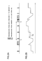
- FIG. 6 shows the data transition in the memory 4 in one embodiment of the digital recording/reproducing apparatus according to the present invention.
- FIG. 6A shows data flowing through the third data control circuit 2c
- FIG. 6B shows a change in an amount Sra of data of an area for recording and a change in an amount Srb of data of an area for reading in the memory 4 in time series.
- a program that does not need to be encrypted is recorded.
- the CPU 3 instructs the third data control circuit 2c to interrupt the transfer of the digital recording data to the DVD drive 8c.
- the digital recording signal to be recorded is continuously flowed and hence the data of the encoded digital recording signal is continuously stored in an area in the memory 4 assigned for recording from the MPEG encoder 11 just as with the case before recording being interrupted.
- the DVD drive 8c and the mutual authentication circuit 9 perform mutual authentication and then.read the information of the base of an encryption key, and an encryption key is generated by the key generation circuit 7.
- the decryption circuit 10 is enabled by the generated encryption key and then the DVD drive 8c starts to read data from the recording medium at a time T9.
- the read data is transferred via the third data control circuit 2c to the memory 4 and is once stored in the area in the memory 4 assigned for reading and then is again transferred via the third data control circuit 2c to the decryption circuit 10.
- the data decrypted by the decryption circuit 10 is again transferred via the third data control circuit 2c to the memory 4 and is stored in an area in the memory 4 assigned for reproducing. Further, when a specified amount of data is stored, the data is transferred to the MPEG decoder 11 that decodes the encoded data.
- the DVD drive 8c reads a specified amount of data and then writes the data to the recording medium each time an amount Sra of data of an area in the memory 4 assigned for recording is more than a specified amount Sr5 of data, and reads data from the recording medium each time an amount Srb of data of an area in the memory 4 assigned for reproducing becomes less than Sr11.
- a digital signal for recording can be stored in the memory 4 during process of enabling the decryption circuit 10 and, after the enabling of the decryption circuit is completed, data read from the DVD drive 8c can be decrypted and reproduced, and at the same time can be recorded on the recording medium in the DVD drive 8c.
- the encryption circuit 10 is enabled, and then reproduces the encrypted program in the middle of recording a program that does not need to be encrypted.
- the encryption circuit 5 is enabled, and then records the data in the middle of reproducing a program that is not encrypted.
- the configuration of the digital recording/reproducing apparatus of this embodiment is the same as the configuration shown in FIG. 5 of the third embodiment.
- FIG. 7 shows the data transition in the memory 4 in another embodiment of a digital recording/reproducing apparatus according to the present invention.
- FIG. 7A shows data flowing through the third data control circuit 2c and
- FIG. 7B shows a change in an amount Sra of data for recording and a change in an amount Srb of data for reproducing in the memory 4 in time series.
- the CPU 3 instructs the MPEG encoder 1 to start to encode data and starts to transfer the data to an area in the memory 4 assigned for recording. Since a video data cannot be reproduced from the recording medium during process of enabling the encryption circuit 5, the enabling of the encryption circuit 5 is started after a time T12a when an amount Sr6 of data large enough for continuously reproducing the video on the display is stored in an area in the memory 4 assigned for reproducing.
- the DVD drive 8c and the mutual authentication circuit 9 perform mutual authentication and then the key generation circuit 7 generates an encryption key from such information of the base of an encryption key that is recorded in the recording medium and the encryption circuit 5 is enabled at a time T12b on the basis of this encryption key.
- the flowing of data for recording the video and the reproducing of the video on the display need to be continuously performed even during process of enabling the encryption circuit 5, and hence the writing of the digital recording signal encoded by the MPEG encoder 1 to an area in the memory 4 assigned for recording is continuously performed. Moreover, the data in the area in the memory 4 assigned for reading is continuously supplied to the MPEG decoder 11.
- the stored data is transferred via the third data control circuit 2c to the encryption circuit 5 and is encrypted by the encryption circuit 5.
- the data is transferred via the third data control circuit 2c to the memory 4 and is again stored in an area in the memory 4 assigned for writing and then is again transferred via the third data control circuit 2c to the interface 6 and then the writing of the data to the recording medium is started by the DVD drive 8c.
- the writing of the data to the recording medium is continuously performed until an amount of data for recording decreases to Sr8. Further, when an amount of data in the area assigned for reproducing is less than Sr9, the DVD drive 8 again starts to read data from the recording medium.
- the reproducing of data from the recording medium cannot be performed during process of enabling the encryption circuit 5 and during a period of time until the data stored in an area in the memory 4 assigned for recording is written to the recording medium. Therefore, it is necessary to start the enabling of the encryption circuit 5 after an amount Sr6 of data enough to continuously reproduce the video on the display for these periods of time is stored in the area assigned for reproducing.
- an amount Sr6 of data to be stored needs to satisfy a relationship formula of Sr 6 > ( T 14 - T 12 a ) ⁇ y .
- a digital signal for recording can be stored in the memory 4 during process of enabling the encryption circuit 5 and after the enabling of the encryption circuit is completed, the digital signal can be encrypted and data can be recoded and at the same time data in the recording medium of the DVD drive 8c can be reproduced.
- data can be recorded or reproduced on and from the recording medium always from a time when the request is made.
- a digital recording apparatus in the fifth embodiment is the same as that in the first embodiment and is the same as that shown in FIG. 1.
- FIG. 8 indicates diagrams showing the data transition in a memory in another embodiment of a digital recording apparatus according to the present invention.
- FIG. 8A shows data flowing through the first data control circuit 2a
- FIG. 8B shows a change in the amount Sra of data of a recording area in the memory 4 in time series.
- the CPU 3 gives the DVD drive 8a a start-up command via the first data control circuit 2a and the interface 6.
- the DVD drive 8a starts rotating the recording medium, sets various servos, and reads information necessary for recording and reproducing data on and from the recording medium. After that the DVD drive 8a notifies the CPU 3 of the completion of preparation via the interface 6 and the first data control circuit 2a.
- the CPU 3 instructs the MPEG encoder 1 to encode a digital recording signal and to input it to the first data control circuit 2a.
- the CPU 3 determines by the CGMS that the digital recording signal needs to be encrypted.
- the MPEG encoder 1 transfers data via the first data control circuit 2a to an area in the memory 4 assigned for recording. This data transfer is finished in a short time because data is transferred between memories at a transfer rate of several hundreds Mbit/sec or more. Thereafter, the data encoded by the MPEG encoder 1 is continuously stored in the memory 4 until the preparation of recording by the DVD drive 8a is completed.
- the start-up of the DVD drive 8a is completed at a time T2a
- the enabling of the encryption circuit 5 is started, and is finished at a time T12b. This makes it possible for the DVD drive 8a to record also the encrypted data.
- the encoded data is continuously stored in the memory 4 also for the duration of time.
- the recording of data on the recording medium is performed via the interface 6 and the DVD drive 8a until an area in the memory 4 assigned for recording becomes not larger than a specified capacity Sr2.
- the writing rate of data on the recording medium by the DVD drive 8a is approximately several tens Mbit/sec and hence the recording of data on the recording medium takes several times as long as the time required to transfer data to the memory 4.
- the bit rate of encoding by the MPEG encoder 1 is x Mbit/sec and that a time when writing data to a magneto-optical disk starts is T3
- the required minimum capacity C4 of the recording area in the memory 4 needs to satisfy a relationship formula of C 4 > x ⁇ ( T 3 - T 1 ) .
- several to several tens kbyte of capacity is adequate for the area in the memory 4 assigned when data is once transferred to the memory 4 from the encryption circuit 5, because data is immediately recorded on the recording medium by the DVD drive 8a.
- the encoded digital recording signal is continuously outputted from the MPEG encoder 1 also after the DVD drive 8a becomes capable of recording data. Since the writing rate of data to the recording medium is faster than the rate of outputting of data by the MPEG encoder 1, the memory 4 does not overflow as shown in FIG. 8. The writing of data to the recording medium is not performed until the area in the memory assigned for recording 4 again reaches a specified capacity. Each time the area exceeds a specified capacity, data is written in a lump.
- FIG. 9 is a system diagram showing another embodiment of a digital recording apparatus according to the present invention. A description of this figure will be made with reference to different points from the system diagram shown in FIG. 1 of the first embodiment.
- information could be transmitted between the first data control circuit 2a and the encryption circuit 5 bidirectionally, information can be transmitted only from the first data control circuit 2a to the encryption circuit 5 in the sixth embodiment.
- both of the first data control circuit 2a and the encryption circuit 5 can transmit information to the selector 12.
- the selector 12 can select data from the first control circuit 2a or data from the encryption circuit 5 to transmit information to the interface 6.
- data that is not encrypted is transferred from the memory 4 via the first data control circuit 2a to the interface 6, whereas in the sixth embodiment, data that is not encrypted is once transferred from the memory 4 via the first data control circuit 2a to the selector 12 and then after the selector 12 selects data that is not encrypted, the data is transferred to the interface 6.
- data is encrypted by the encryption circuit 5 and then the encrypted data is returned via the first data control circuit 2a to an area in the memory 4 assigned.for writing and then is outputted via the first data control circuit 2a to the interface 6, whereas in the sixth embodiment, data is encrypted by the encryption circuit 5 and then the encrypted data is once transferred to the selector 12 and after the selector 12 selects the encrypted data, the encrypted data is transferred to the interface 6.
- the encrypted data is not returned via the first data control circuit 2a to an area in the memory 4 assigned for writing and hence an area in the memory 4 assigned for writing does not need to be secured. Moreover, since an amount of data per unit time passing through the first data control circuit 2a becomes small, a data transfer rate can be made slower than in the first and fifth embodiments, which results in reducing the size of the system and further reducing power consumption.
- FIG. 10 is a system diagram showing another embodiment of a digital reproducing apparatus according to the present invention. A description of this figure will be made with reference to different points from the system diagram shown in FIG. 3 of the second embodiment.
- information could be transmitted between the second data control circuit 2b and the decryption circuit 10 bidirectionally, information can be transmitted only from the second data control circuit 2b to the decryption circuit 10 in the seventh embodiment.
- both of the second data control circuit 2b and the decryption circuit 10 can transmit information to the selector 13.
- the selector 13 can select data from the second control circuit 2c or data from the decryption circuit 10 to transmit information to the MPEG decoder 11.
- data that does not need to be decrypted is transferred from the memory 4 via the second data control circuit 2b to the MPEG decoder 11, whereas in the seventh embodiment, data that does not need to be decrypted is once transferred from the second data control circuit 2b to the selector 13 and then after the selector 13 selects the data that does not need to be decrypted, the data is transferred to the MPEG decoder 11.
- data is decrypted by the decryption circuit 10, and then the decrypted data is returned via the second data control circuit 2b to an area in the memory 4 assigned for reproducing and further is outputted via the second data control circuit 2b to the MPEG decoder 11.
- data is decrypted by the decryption circuit 10 and then the decrypted data is transferred to the selector 13, and after the selector 13 selects the decrypted data, the decrypted data is transferred to the MPEG decoder 11.
- FIG. 11 is a system diagram showing another embodiment of a digital recording/reproducing apparatus according to the present invention. A description of this figure will be made with reference to different points from the system diagram shown in FIG. 5 of the third embodiment.
- both of the third data control circuit 2c and the encryption circuit 5 can transmit information to the selector 12.
- the selector 12 can select data from the first control circuit 2a or data from the encryption circuit 5 to transmit information to the interface 6.
- both of the third data control circuit 2c and the decryption circuit 10 can transmit information to the selector 13.
- the selector 13 can select data from the third control circuit 2c or data from the decryption circuit 10 to transmit information to the MPEG decoder 11.
- the encrypted data is not returned via the third data control circuit 2c to an area in the memory 4 assigned for writing.
- the area in the memory 4 for writing does not need to be secured.
- a data transfer rate can be made slower than that in the third and fourth embodiments, which results in reducing the size of the system and further reducing power consumption.
- the decrypted data is not returned via the third data control circuit 2c to an area in the memory 4 assigned for reproducing. Hence the area in the memory 4 for reproducing does not need to be secured. Moreover, since an amount of data per unit time passing through the third data control circuit 2c becomes smaller, a data transfer rate can be made slower than that in the third and fourth embodiments, which results in reducing the size of the system and further reducing power consumption.
- the descriptions have been made on the precondition that mutual authentication is performed between the DVD drives 8a to 8c and the mutual authentication circuit 9.
- the mutual authentication circuit 9 is not necessary.
- the MPEG encoder 1 and the MPEG decoder 11 are used for encoding and decoding data have been described, encoders and decoders of other types can be employed, and when encoding is not necessary, it is not necessary to provide an encoder and a decoder.
- the DVD recorder (recording apparatus) or the DVD player (reproducing apparatus) has been described in the first to eighth embodiments, but the present invention can be applied also to a recording apparatus and a reproducing apparatus using a hard disk or a semiconductor memory.
- a digital recording apparatus a digital reproducing apparatus, a digital recording/reproducing apparatus, an encryption apparatus, a decryption apparatus, an encryption method, and a decryption method of the present invention
- recording or reproducing can be performed smoothly always from when a request is made.
Landscapes
- Engineering & Computer Science (AREA)
- Signal Processing (AREA)
- Computer Security & Cryptography (AREA)
- Multimedia (AREA)
- Signal Processing For Digital Recording And Reproducing (AREA)
- Storage Device Security (AREA)
Applications Claiming Priority (2)
| Application Number | Priority Date | Filing Date | Title |
|---|---|---|---|
| JP2003285689 | 2003-08-04 | ||
| PCT/JP2004/010218 WO2005013273A1 (ja) | 2003-08-04 | 2004-07-16 | ディジタル記録装置、ディジタル再生装置及びディジタル記録再生装置、並びに、暗号化装置、暗号復調装置、暗号化方法及び暗号復調方法 |
Publications (2)
| Publication Number | Publication Date |
|---|---|
| EP1662504A1 true EP1662504A1 (de) | 2006-05-31 |
| EP1662504A4 EP1662504A4 (de) | 2011-04-20 |
Family
ID=34113891
Family Applications (1)
| Application Number | Title | Priority Date | Filing Date |
|---|---|---|---|
| EP04747683A Withdrawn EP1662504A4 (de) | 2003-08-04 | 2004-07-16 | Digitale aufzeichnungseinrichtung, digitale wiedergabeeinrichtung, digitale aufzeichnungs-/wiedergabeeinrichtung, verschlüsselungseinrichtung, entschlüsselungseinrichtung, verschlüsselungsverfahren und entschlüsselungsverfahren |
Country Status (6)
| Country | Link |
|---|---|
| US (1) | US7783039B2 (de) |
| EP (1) | EP1662504A4 (de) |
| JP (1) | JP4509030B2 (de) |
| CN (1) | CN1799095A (de) |
| TW (1) | TWI285367B (de) |
| WO (1) | WO2005013273A1 (de) |
Families Citing this family (7)
| Publication number | Priority date | Publication date | Assignee | Title |
|---|---|---|---|---|
| JP5026049B2 (ja) * | 2006-10-25 | 2012-09-12 | ソニー株式会社 | メディアドライブ装置、メディアドライブ装置の動作方法、プログラム、プログラム記録媒体 |
| US9281004B2 (en) * | 2006-12-11 | 2016-03-08 | Mitsubishi Electric Corporation | Content assessment apparatus, content assessment method, information reproducing apparatus, and information reproducing method |
| US8965183B1 (en) * | 2008-01-30 | 2015-02-24 | Dominic M. Kotab | Systems and methods for creating and storing reduced quality video data |
| US8646046B2 (en) * | 2008-05-15 | 2014-02-04 | Advanced Micro Devices, Inc. | Distributed digital rights management system and method |
| US9232174B1 (en) | 2008-06-25 | 2016-01-05 | Dominic M. Kotab | Methods for receiving and sending video to a handheld device |
| JP5055254B2 (ja) * | 2008-12-19 | 2012-10-24 | 日立コンシューマエレクトロニクス株式会社 | 映像伝送システム及びedidの読み出し方法 |
| WO2016056473A1 (ja) * | 2014-10-07 | 2016-04-14 | 日本電信電話株式会社 | 秘密計算システム、中継装置、それらの方法、プログラム、および記録媒体 |
Citations (6)
| Publication number | Priority date | Publication date | Assignee | Title |
|---|---|---|---|---|
| EP0789361A2 (de) * | 1996-02-06 | 1997-08-13 | Matsushita Electric Industrial Co., Ltd. | Zur Vermeidung ungesetzliches kopierens von Dokumenten geeignetes Datenempfangsgerät, Datenübertragungsgerät, Informationsverarbeitungssystem, Datempfangsverfahren und Informationsaufzeichnungsmedium |
| EP0802535A1 (de) * | 1995-10-09 | 1997-10-22 | Matsushita Electric Industrial Co., Ltd. | Informationsaufzeichnungsträger, informationswiedergabegerät und informationswiedergabeverfahren |
| EP1081699A1 (de) * | 1999-09-03 | 2001-03-07 | Sony Corporation | Wiedergabe- und Aufzeichnungsgerät für kopiergeschützte und nicht kopiergeschützte Dateien |
| US20010033660A1 (en) * | 2000-01-21 | 2001-10-25 | Mitsuru Maeda | Information processing apparatus and method |
| EP1209580A2 (de) * | 2000-09-29 | 2002-05-29 | Kabushiki Kaisha Toshiba | Gerät zum Empfang von digitalen Rundfunksignalen und für die Erzeugung eines Wiedergabesignals aus den digitalen Rundfunksignalen und Verfahren für die Steuerung dieses Gerätes |
| US20020123968A1 (en) * | 2000-06-29 | 2002-09-05 | Mutsuyuki Okayama | Copyright protective device and method |
Family Cites Families (8)
| Publication number | Priority date | Publication date | Assignee | Title |
|---|---|---|---|---|
| US4368357A (en) * | 1980-11-14 | 1983-01-11 | International Telephone And Telegraph Corporation | Bypass apparatus for use in secure communication systems |
| JPS63287882A (ja) * | 1987-05-20 | 1988-11-24 | 株式会社日立製作所 | 暗号装置 |
| JP3073590B2 (ja) * | 1992-03-16 | 2000-08-07 | 富士通株式会社 | 電子化データ保護システム、使用許諾者側装置および使用者側装置 |
| US5303302A (en) * | 1992-06-18 | 1994-04-12 | Digital Equipment Corporation | Network packet receiver with buffer logic for reassembling interleaved data packets |
| JPH08306133A (ja) | 1995-04-28 | 1996-11-22 | Sony Corp | デジタル記録装置及びデジタル記録再生装置 |
| JP4482970B2 (ja) * | 1999-09-02 | 2010-06-16 | ソニー株式会社 | Dvdレコーダ、dvdレコーダの記録再生方法、およびプログラム記録媒体 |
| JP2002064482A (ja) | 2000-08-23 | 2002-02-28 | Matsushita Electric Works Ltd | 暗号処理装置 |
| JP2002344440A (ja) | 2001-05-21 | 2002-11-29 | Toshiba Corp | データ再生装置、データ再生方法、データ再生プログラム、およびビデオ・オン・デマンド・システム |
-
2004
- 2004-07-16 JP JP2005512470A patent/JP4509030B2/ja not_active Expired - Fee Related
- 2004-07-16 WO PCT/JP2004/010218 patent/WO2005013273A1/ja active Application Filing
- 2004-07-16 EP EP04747683A patent/EP1662504A4/de not_active Withdrawn
- 2004-07-16 US US10/566,728 patent/US7783039B2/en not_active Expired - Fee Related
- 2004-07-16 CN CN200480014980.5A patent/CN1799095A/zh active Pending
- 2004-07-28 TW TW093122501A patent/TWI285367B/zh not_active IP Right Cessation
Patent Citations (6)
| Publication number | Priority date | Publication date | Assignee | Title |
|---|---|---|---|---|
| EP0802535A1 (de) * | 1995-10-09 | 1997-10-22 | Matsushita Electric Industrial Co., Ltd. | Informationsaufzeichnungsträger, informationswiedergabegerät und informationswiedergabeverfahren |
| EP0789361A2 (de) * | 1996-02-06 | 1997-08-13 | Matsushita Electric Industrial Co., Ltd. | Zur Vermeidung ungesetzliches kopierens von Dokumenten geeignetes Datenempfangsgerät, Datenübertragungsgerät, Informationsverarbeitungssystem, Datempfangsverfahren und Informationsaufzeichnungsmedium |
| EP1081699A1 (de) * | 1999-09-03 | 2001-03-07 | Sony Corporation | Wiedergabe- und Aufzeichnungsgerät für kopiergeschützte und nicht kopiergeschützte Dateien |
| US20010033660A1 (en) * | 2000-01-21 | 2001-10-25 | Mitsuru Maeda | Information processing apparatus and method |
| US20020123968A1 (en) * | 2000-06-29 | 2002-09-05 | Mutsuyuki Okayama | Copyright protective device and method |
| EP1209580A2 (de) * | 2000-09-29 | 2002-05-29 | Kabushiki Kaisha Toshiba | Gerät zum Empfang von digitalen Rundfunksignalen und für die Erzeugung eines Wiedergabesignals aus den digitalen Rundfunksignalen und Verfahren für die Steuerung dieses Gerätes |
Non-Patent Citations (1)
| Title |
|---|
| See also references of WO2005013273A1 * |
Also Published As
| Publication number | Publication date |
|---|---|
| JPWO2005013273A1 (ja) | 2006-09-28 |
| WO2005013273A1 (ja) | 2005-02-10 |
| EP1662504A4 (de) | 2011-04-20 |
| US20060210074A1 (en) | 2006-09-21 |
| US7783039B2 (en) | 2010-08-24 |
| TW200506866A (en) | 2005-02-16 |
| TWI285367B (en) | 2007-08-11 |
| CN1799095A (zh) | 2006-07-05 |
| JP4509030B2 (ja) | 2010-07-21 |
Similar Documents
| Publication | Publication Date | Title |
|---|---|---|
| JP3785983B2 (ja) | ディジタル情報記録装置および情報記録再生装置 | |
| KR100491903B1 (ko) | 디지털 정보 기록 장치 및 출력 장치 | |
| US20070183747A1 (en) | Digital signal recording and playback apparatus | |
| JP2002238023A (ja) | ディジタル情報記録装置、再生装置および送信装置 | |
| JP4299976B2 (ja) | ディジタル情報記録装置 | |
| US7783039B2 (en) | Digital recording device, digital reproduction device, digital recording/reproduction device, encryption device, decryption device, encryption method, and decryption method | |
| JP3937889B2 (ja) | ディジタル情報記録再生装置 | |
| JP4340694B2 (ja) | ディジタル情報送信装置、ディジタル情報送信方法、ディジタル情報受信装置およびディジタル情報受信方法 | |
| JP2004063016A (ja) | 情報記録方法および情報記録再生装置 | |
| JP4538414B2 (ja) | ディジタル情報記録再生装置、ディジタル情報受信装置およびディジタル情報送受信システム | |
| JP2007287268A (ja) | 記録装置 | |
| JP4637254B2 (ja) | ディジタル情報受信装置、ディジタル情報受信方法、ディジタル情報送受信方法及びディジタル情報送信方法 | |
| JP4597231B2 (ja) | ディジタル情報記録再生装置、ディジタル情報受信装置、ディジタル情報送受信システム、ディジタル情報受信方法、およびディジタル情報送受信方法 | |
| JP4919928B2 (ja) | ディジタル情報受信装置、および、ディジタル情報出力方法 | |
| JP5178037B2 (ja) | ディジタル情報記録装置およびディジタル情報記録方法ディジタル情報送信装置およびディジタル情報送信方法、ディジタル情報処理装置およびディジタル情報処理方法 | |
| JP4340693B2 (ja) | ディジタル情報受信装置、ディジタル情報受信方法およびディジタル情報送信方法 | |
| JP4340695B2 (ja) | ディジタル情報受信装置、ディジタル情報受信方法およびディジタル情報送信方法 | |
| JP4162033B2 (ja) | ディジタル情報記録再生装置 | |
| JP4254903B2 (ja) | ディジタル放送信号受信装置およびディジタル放送信号受信方法 | |
| JP4123290B2 (ja) | ディジタル情報記録再生装置およびディジタル情報記録再生方法 | |
| JP4876180B2 (ja) | ディジタル情報記録再生装置、ディジタル情報記録再生方法、ディジタル情報送信方法、および、ディジタル情報送受信方法 | |
| JP2007257825A (ja) | ディジタル情報受信装置およびディジタル情報受信方法 | |
| JP2005216346A (ja) | デジタル記録再生装置 | |
| JP2008257847A (ja) | ディジタル放送信号受信方法 |
Legal Events
| Date | Code | Title | Description |
|---|---|---|---|
| PUAI | Public reference made under article 153(3) epc to a published international application that has entered the european phase |
Free format text: ORIGINAL CODE: 0009012 |
|
| 17P | Request for examination filed |
Effective date: 20060227 |
|
| AK | Designated contracting states |
Kind code of ref document: A1 Designated state(s): DE GB |
|
| DAX | Request for extension of the european patent (deleted) | ||
| RBV | Designated contracting states (corrected) |
Designated state(s): DE GB |
|
| A4 | Supplementary search report drawn up and despatched |
Effective date: 20110321 |
|
| 17Q | First examination report despatched |
Effective date: 20111118 |
|
| STAA | Information on the status of an ep patent application or granted ep patent |
Free format text: STATUS: THE APPLICATION IS DEEMED TO BE WITHDRAWN |
|
| 18D | Application deemed to be withdrawn |
Effective date: 20150203 |