EP1662220A2 - Plate-like heat exchanger - Google Patents
Plate-like heat exchanger Download PDFInfo
- Publication number
- EP1662220A2 EP1662220A2 EP05023429A EP05023429A EP1662220A2 EP 1662220 A2 EP1662220 A2 EP 1662220A2 EP 05023429 A EP05023429 A EP 05023429A EP 05023429 A EP05023429 A EP 05023429A EP 1662220 A2 EP1662220 A2 EP 1662220A2
- Authority
- EP
- European Patent Office
- Prior art keywords
- plate
- flow path
- flow paths
- crossing
- heat exchanger
- Prior art date
- Legal status (The legal status is an assumption and is not a legal conclusion. Google has not performed a legal analysis and makes no representation as to the accuracy of the status listed.)
- Granted
Links
Images


Classifications
-
- B—PERFORMING OPERATIONS; TRANSPORTING
- B60—VEHICLES IN GENERAL
- B60H—ARRANGEMENTS OF HEATING, COOLING, VENTILATING OR OTHER AIR-TREATING DEVICES SPECIALLY ADAPTED FOR PASSENGER OR GOODS SPACES OF VEHICLES
- B60H1/00—Heating, cooling or ventilating devices
- B60H1/00507—Details, e.g. mounting arrangements, desaeration devices
- B60H1/00514—Details of air conditioning housings
- B60H1/0055—Details of air conditioning housings the housing or parts thereof being integrated in other devices, e.g. dashboard
-
- F—MECHANICAL ENGINEERING; LIGHTING; HEATING; WEAPONS; BLASTING
- F24—HEATING; RANGES; VENTILATING
- F24F—AIR-CONDITIONING; AIR-HUMIDIFICATION; VENTILATION; USE OF AIR CURRENTS FOR SCREENING
- F24F5/00—Air-conditioning systems or apparatus not covered by F24F1/00 or F24F3/00, e.g. using solar heat or combined with household units such as an oven or water heater
- F24F5/0089—Systems using radiation from walls or panels
- F24F5/0092—Systems using radiation from walls or panels ceilings, e.g. cool ceilings
-
- F—MECHANICAL ENGINEERING; LIGHTING; HEATING; WEAPONS; BLASTING
- F28—HEAT EXCHANGE IN GENERAL
- F28D—HEAT-EXCHANGE APPARATUS, NOT PROVIDED FOR IN ANOTHER SUBCLASS, IN WHICH THE HEAT-EXCHANGE MEDIA DO NOT COME INTO DIRECT CONTACT
- F28D1/00—Heat-exchange apparatus having stationary conduit assemblies for one heat-exchange medium only, the media being in contact with different sides of the conduit wall, in which the other heat-exchange medium is a large body of fluid, e.g. domestic or motor car radiators
- F28D1/02—Heat-exchange apparatus having stationary conduit assemblies for one heat-exchange medium only, the media being in contact with different sides of the conduit wall, in which the other heat-exchange medium is a large body of fluid, e.g. domestic or motor car radiators with heat-exchange conduits immersed in the body of fluid
- F28D1/03—Heat-exchange apparatus having stationary conduit assemblies for one heat-exchange medium only, the media being in contact with different sides of the conduit wall, in which the other heat-exchange medium is a large body of fluid, e.g. domestic or motor car radiators with heat-exchange conduits immersed in the body of fluid with plate-like or laminated conduits
- F28D1/0308—Heat-exchange apparatus having stationary conduit assemblies for one heat-exchange medium only, the media being in contact with different sides of the conduit wall, in which the other heat-exchange medium is a large body of fluid, e.g. domestic or motor car radiators with heat-exchange conduits immersed in the body of fluid with plate-like or laminated conduits the conduits being formed by paired plates touching each other
- F28D1/035—Heat-exchange apparatus having stationary conduit assemblies for one heat-exchange medium only, the media being in contact with different sides of the conduit wall, in which the other heat-exchange medium is a large body of fluid, e.g. domestic or motor car radiators with heat-exchange conduits immersed in the body of fluid with plate-like or laminated conduits the conduits being formed by paired plates touching each other with U-flow or serpentine-flow inside the conduits
-
- F—MECHANICAL ENGINEERING; LIGHTING; HEATING; WEAPONS; BLASTING
- F28—HEAT EXCHANGE IN GENERAL
- F28F—DETAILS OF HEAT-EXCHANGE AND HEAT-TRANSFER APPARATUS, OF GENERAL APPLICATION
- F28F3/00—Plate-like or laminated elements; Assemblies of plate-like or laminated elements
- F28F3/12—Elements constructed in the shape of a hollow panel, e.g. with channels
Definitions
- the present invention relates to a plate-like heat exchanger.
- Heat exchangers are used for various purposes such as heat exchanging in an air-conditioner.
- the heat exchangers need to be formed in a thin shape.
- Japanese Patent Application Laid-open No. 2003-161547 discloses an art providing a heat exchanger formed in a relatively thin shape.
- a hollow plate portion is formed at a center of a housing to be used as a flow path for flow of coolant. Both ends of the housing are used as a tank for pooling the coolant.
- the present invention is intended for providing a plate-like heat exchanger.
- a plate-like heat exchanger is provided with a plate-like structure; one or more flow paths respectively including opened ends, the flow paths being formed in an interior of the plate-like structure and running in a first direction; one or more covering members fixed to the plate-like structure, at least one end of the covering members extending to reach any one or more peripheries of the plate-like structure; one or more crossing flow paths defined by the covering members and the plate-like structure, the crossing flow paths being directed to a second direction intersecting the first direction and respectively being linked with the opened ends of the flow paths; and inflow and outflow ports respectively for inflow and outflow of a fluid, the ports respectively being formed at the ends of the covering members at the peripheries of the plate-like structure and linked with the crossing flow paths.
- the plate-like structure comprises three plate bodies accumulated with each other and the flow paths are formed between the plate bodies.
- the plate-like structure comprises three or more plate bodies accumulated one on one and the flow paths are formed at respective interfaces of the plate bodies. More preferably, the inflow port is linked with all the flow paths formed at the respective interfaces so that the fluid is branched to flow all the flow paths.
- the plate bodies and the covering members are joined with each other by diffusion bonding.
- crossing flow path are formed to have a cross-sectional area greater than a cross-sectional area of the inflow port.
- An embodiment of the present invention achieves the purpose of provision of a plate-like heat exchanger by forming plural flow paths in a plate-like structure having a predetermined thickness, forming crossing flow paths at both ends of the flow paths perpendicularly thereto, tightly closing the crossing flow paths with covering members accumulated on the plate-like structure and directed along a lateral direction of the plate-like structure; extending the crossing flow paths in part to reach peripheries of the plate-like structure; and forming inflow and outflow ports at the extended crossing flow paths.
- the embodiment of the present invention will be described hereinafter with reference to Figs. 1 through 7.
- a plate-like heat exchanger 2 in accordance with the present embodiment may be applied to a vehicle in a manner shown in Figs. 1 and 2.
- Four plates of the plate-like heat exchangers 2 are installed in a roof of the vehicle so as to be leveled with the ground and arranged side by side, for example.
- the plate-like heat exchangers 2 are specially installed therein as being separated from the other members of the air-conditioner installed in the vehicle compartment for the purpose of reducing thermal load by thermal insulation at the roof and accomplishing face air-conditioning by radiation at the roof.
- the plate-like heat exchangers 2 have a common constitution and Figs. 3 through 7 illustrate one of them to show the structure thereof.
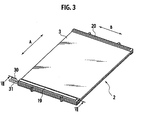
- the plate-like heat exchanger 2 is formed to be of a rectangle.
- a first direction A is defined to be a longitudinal direction of the rectangle and a refrigerant fluid R flows in the first direction A.
- a second direction B is defined as a direction crossing to the first direction A.
- the plate-like heat exchanger 2 is provided with an upper plate body 3, a central plate body 4 and a lower plate body 5, all of which are made of a metal.
- a margin along one end of the upper plate body 3 is cut out along the second direction B to form a first crossing flow path 6.
- the first crossing flow path 6 spans a half of the upper plate body 3 in a lateral direction and is drawn to one side of the upper plate body 3.
- the margin of the upper plate body 3 is further cut out along the first crossing flow path 6 and nearer to the end of the upper plate body 3 to form an auxiliary flow path 7, which has substantially the same length as the first crossing flow path 6.
- the first crossing flow path 6 is extended to the side of the upper plate body 3 and, there, a side margin of the upper plate body 3 is cut out to form an inflow port 8. Similarly, an outflow port 9 is formed at the side margin to correspond to the auxiliary flow path 7.
- a margin along another end of the upper plate body 3 is likewise cut out to form a second crossing flow path 10 though the second crossing flow path 10 substantially extends from one side to another side of the upper plate body 3 differently from the first crossing flow path 6.
- a third crossing flow path 11 is formed on an extension of the auxiliary flow path 7 at the remaining half of the upper plate body 3.
- the first crossing flow path 6, the auxiliary flow path 7, the second crossing flow path 10, the third crossing flow path 11 and any equivalents have bridge portions 12 bridging the respective flow paths in these lateral directions for preventing deformation thereof.
- the central plate body 4 is also cut out correspondingly to the auxiliary flow path 7 and the third crossing flow path 11 to form an auxiliary flow path 14.
- the opposite end of the central plate body 4 has no flow paths.
- the auxiliary flow path 14 is extended to one side of the central plate body 4 and, there, a side margin of the central plate body 4 is cut out.
- the cut out portion is to compose the inflow port 8. Adjacent thereto, further the central plate body 4 is cut out to compose the outflow port 9. Except for the auxiliary flow path 14 and the cut out portions, the central plate body 4 is formed to be flat and do not have any recesses and cuttings.
- the lower plate body 5 is somewhat similar to the upper plate body 3, however, a fourth crossing flow path 15 is formed at an opposite half of the lower plate body 5 as compared with the first crossing flow path 6 of the upper plate body 3.
- a fifth crossing flow path 16 is formed at an opposite end of the lower plate body 5 correspondingly to the second crossing flow path 10 of the upper plate body 3.
- a sixth flow path 17 is formed on the lower plate body 5 correspondingly to the auxiliary flow path 7 of the upper plate body 3.
- An auxiliary flow path 18 of the lower plate body 5 is formed on an extension of the sixth crossing flow path 17 at the remaining half of the lower plate body 5.
- the sixth crossing flow path 17 is extended to the side of the lower plate body 5 and, there, a side margin of the lower plate body 5 is cut out to compose the outflow port 9. Adjacent thereto, further the lower plate body 5 is cut out to compose the inflow port 8.
- a pair of upper covering members 19 and 20 are joined on both the end margins of the upper plate body 3 respectively, on a face opposite to the face facing to the central plate body 4.
- the upper covering member 19 on a face facing to the upper plate body 3 has grooves 23, one of which is correspondent to the first crossing flow path 6 and another of which is correspondent to the auxiliary flow path 7 and the third crossing flow path 11.
- the former groove 23 has a partition 24 correspondent to an end of the first crossing flow path 6 as shown in Fig. 4B.
- the upper covering member 20 on a face facing to the upper plate body 3 has a groove 25 correspondent to the second crossing flow path 10.
- a pair of lower covering members 21 and 22 are joined on both the end margins of the lower plate body 5 respectively, on a face opposite to the face facing to the central plate body 4.
- the lower covering member 21 on a face facing to the lower plate body 5 has grooves 26, one of which is correspondent to the fourth crossing flow path 15 and another of which is correspondent to the sixth crossing flowpath 17 and the auxiliary flow path 18.
- the lower covering member 22 on a face facing to the lower plate body 5 has a groove 27 correspondent to the fifth crossing flow path 16.
- the upper plate body 3, the central plate body 4, the lower plate body 5, the upper covering member 19 and 20 and the lower covering member 21 and 22 are accumulated in this order and positioned so that the correspondent elements are aligned with each other.
- these members are set in an appropriate joining apparatus (not shown), pressed and heated from the top and the bottom.
- the plate body bodies 3, 4 and 5 and the covering members 19, 20, 21 and 22 are joined with each other by diffusion bonding since these members are made of metal which is preferable to bringing about the diffusion bonding. Therefore production of the plate-like heat exchanger 2 is easy to be accomplished.
- the upper plate body 3 and the center plate body 4 compose an upper plate-like structure 28.
- the flow paths 13 are formed in an interior of the upper plate-like structure 28 and run in the first direction A.
- the lower plate body 5 and the central plate body 4 compose a lower plate-like structure 29.
- the flow paths 13 are formed in an interior of the lower plate-like structure 29 and run in the first direction A. More specifically, two plate-like structure 28 and 29 are simultaneously formed in a back-to-back state by the upper plate body 3, the central plate body 4 and the lower plate body 5 in a state of using the central plate body 4 together.
- the first crossing flow path 6, the second crossing flow path 10, the third crossing flow path 11, the fourth crossing flow path 15, the fifth crossing flow path 16, the sixth crossing flow path 17 and the auxiliary flow paths 7, 14 and 18 are defined by the upper coveringmembers 19 and 20, the lower coveringmembers 21 and 22 and the plate-like structures 28 and 29. Respectively to the inflow port 8 and the outflow port 9, an inflow pipe 30 and an outflow pipe 31 are inserted and brazed. Thereby the plate-like heat exchanger 2 is produced.
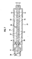
- Fig. 7 When the refrigerant fluid R flows into the inflow pipe 30, the refrigerant fluid R is branched to the upper plate-like structure 28 and the lower plate-like structure 29. Then, because the plate-like heat exchanger 2 is leveled horizontally, a gaseous fluid having a low density derived from the refrigerant fluid R flows through the upper plate-like structure 28 as a result of branching. As well, a liquid fluid having a high density derived from the refrigerant fluid R flows through the lower plate-like structure 29.
- a cross-sectional area D1 corresponding to the flow into the upper plate-like structure 28 is substantially equal to (or may be smaller than) a total cross-sectional area D2 of cross sections of the first crossing flow path 6 and the groove 23. Therefore increase in resistance against the flow is avoided and hence the refrigerant fluid R smoothly circulates to the flow path 13.
- the refrigerant fluid R flowing through the upper plate-like structure 28 next flows through the first crossing flow path 6 into the flow paths 13 linked with the first crossing flow path 6. Then, the partition 24 formed at a midway of the groove 23 of the upper coveringmember 19 prevents the refrigerant fluid R from flowing beyond the partition 24. Thereby, the gaseous refrigerant fluid R is prevented from stagnating in an innermost part.
- the refrigerant fluid R flowing into the flow paths 13 further flows through the flow paths 13 and reaches the second crossing flow path 10 at the same half of the upper plate-like structure 28 as where the first crossing flow path 6 exists.
- the refrigerant fluid R further flows through the second crossing flow path 10 toward the remaining half and flows into the flow paths 13 at the remaining half.
- the refrigerant fluid R flows into the third crossing flow path 11 and flows through the auxiliary flow path 7. Finally, the refrigerant fluid R flows out of the outflow port 9.
- flow of the refrigerant fluid R in the lower plate-like structure 29 is generally opposed to the flow in the upper plate-like structure 28. More specifically, the refrigerant fluid R flowing into the inflow pipe 30 flows through the groove 26 of the lower covering member 21 and reaches the fourth crossing flow path 15, and then flows into the flow path 13.
- a cross-sectional area E1 corresponding to the flow into the lower plate-like structure 29 is substantially equal to (or may be smaller than) a total cross-sectional area E2 of cross sections of the fourth crossing flow path 15 and the groove 26. Therefore increase in resistance against the flow is avoided and hence the refrigerant fluid R smoothly circulates to the flow path 13.
- the refrigerant fluid R flowing into the flow paths 13 further flows through the flow paths 13 and reaches the fifth crossing flow path 16 at the same half of the lower plate-like structure 29 as where the fourth crossing flow path 15 exists.
- the refrigerant fluid R further flows through the fifth crossing flow path 16 toward the remaining half and flows into the flow paths 13 at the remaining half. Then the refrigerant fluid R flows back to the sixth crossing flow path 17.
- the refrigerant fluid R next flows out of the outflow port 9.
- the refrigerant fluid R partly flows into the auxiliary flow path 19, however, no problem may be raised because the high-density liquid refrigerant fluid R is unlikely to stagnate in an innermost part.
- the plate-like heat exchanger 2 may be constituted in a prominently thin shape because the thickness thereof is given by only the plate-like structures 28 and 29 and the covering members 19, 20, 21 and 22.
- the production of the plate-like heat exchanger 2 can be easily accomplished because the production requires no troublesome procedures except for accumulating and joining the plate-like structures 28 and 29 and the covering members 19, 20, 21 and 22.
- both the upper plate-like structure 28 and the lower plate-like structure 29 can conduct the refrigerant fluid R, a total flow rate of the refrigerant fluid R can be increased so that efficiency of exchanging heat can improved.
- the plate-like heat exchanger 2 is capable of distributing the refrigerant fluid R into the gaseous part and the liquid part and respectively conducting them through the upper plate-like structure 28 and the lower plate-like structure 29.
- the flow of the gaseous part having a low density tends to be biased in the vicinity of the inflow port 8 though the flow of the liquid part having a high density tends to flow apart from the inflow port 8.
- Such biased flows cause nonuniformity of temperature distribution.
- the plate-like heat exchanger 2 improves uniformity of temperature distribution because the gaseous part and the liquid part independently flow therethrough.
- the invention may be alternatively embodied by modifying the aforementioned embodiment.
- the plate-like structures 28 and 29 may be independently formed and used.
- the inflow port 8 and the outflow port 9 are unnecessary to be formed adjacent to each other.
- the plate-like heat exchanger 2 may be used in an upright position instead of the horizontal position described above.
Landscapes
- Engineering & Computer Science (AREA)
- Mechanical Engineering (AREA)
- General Engineering & Computer Science (AREA)
- Physics & Mathematics (AREA)
- Thermal Sciences (AREA)
- Life Sciences & Earth Sciences (AREA)
- Sustainable Development (AREA)
- Chemical & Material Sciences (AREA)
- Combustion & Propulsion (AREA)
- Heat-Exchange Devices With Radiators And Conduit Assemblies (AREA)
- Air-Conditioning For Vehicles (AREA)
Abstract
Description
- The present invention relates to a plate-like heat exchanger.
- Heat exchangers are used for various purposes such as heat exchanging in an air-conditioner. In certain cases, the heat exchangers need to be formed in a thin shape.
- Japanese Patent Application Laid-open No. 2003-161547 discloses an art providing a heat exchanger formed in a relatively thin shape. In this art, a hollow plate portion is formed at a center of a housing to be used as a flow path for flow of coolant. Both ends of the housing are used as a tank for pooling the coolant.
- Prior arts such as the aforementioned art had limit in down-sizing with respect to thickness of the heat exchangers. The present invention is intended for providing a plate-like heat exchanger.
- According to an aspect of the present invention, a plate-like heat exchanger is provided with a plate-like structure; one or more flow paths respectively including opened ends, the flow paths being formed in an interior of the plate-like structure and running in a first direction; one or more covering members fixed to the plate-like structure, at least one end of the covering members extending to reach any one or more peripheries of the plate-like structure; one or more crossing flow paths defined by the covering members and the plate-like structure, the crossing flow paths being directed to a second direction intersecting the first direction and respectively being linked with the opened ends of the flow paths; and inflow and outflow ports respectively for inflow and outflow of a fluid, the ports respectively being formed at the ends of the covering members at the peripheries of the plate-like structure and linked with the crossing flow paths.
- Preferably, the plate-like structure comprises three plate bodies accumulated with each other and the flow paths are formed between the plate bodies.
- Preferably, the plate-like structure comprises three or more plate bodies accumulated one on one and the flow paths are formed at respective interfaces of the plate bodies. More preferably, the inflow port is linked with all the flow paths formed at the respective interfaces so that the fluid is branched to flow all the flow paths.
- More preferably, the plate bodies and the covering members are joined with each other by diffusion bonding.
- Further preferably, the crossing flow path are formed to have a cross-sectional area greater than a cross-sectional area of the inflow port.
-
- Fig. 1 is a schematically shown cross sectional view of a vehicle having a plate-like heat exchanger installed in a roof thereof;
- Fig. 2 is a schematically shown top view of the vehicle;
- Fig. 3 is a perspective view of a plate-like heat exchanger in accordance with an embodiment of the present invention;
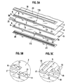
- Fig. 4A is an exploded perspective view of the plate-like heat exchanger;
- Fig. 4B is an enlarged rear view of an upper cover member of the plate-like heat exchanger, corresponding to a circle referred as IVB in Fig. 4A;
- Fig. 5A is an exploded perspective partial view showing one end of the plate-like heat exchanger;
- Figs. 5B and 5C are enlarged perspective partial view of plates composing the plate-like heat exchanger, respectively taken from circles referred as VB and VC in Fig. 5A;
- Fig. 6 is an exploded perspective partial view showing another end of the plate-like heat exchanger; and
- Fig. 7 is a cross sectional view taken along the VII-VII line of Fig. 3.
- An embodiment of the present invention, which will be described hereinafter, achieves the purpose of provision of a plate-like heat exchanger by forming plural flow paths in a plate-like structure having a predetermined thickness, forming crossing flow paths at both ends of the flow paths perpendicularly thereto, tightly closing the crossing flow paths with covering members accumulated on the plate-like structure and directed along a lateral direction of the plate-like structure; extending the crossing flow paths in part to reach peripheries of the plate-like structure; and forming inflow and outflow ports at the extended crossing flow paths. The embodiment of the present invention will be described hereinafter with reference to Figs. 1 through 7.
- A plate-
like heat exchanger 2 in accordance with the present embodiment may be applied to a vehicle in a manner shown in Figs. 1 and 2. Four plates of the plate-like heat exchangers 2 are installed in a roof of the vehicle so as to be leveled with the ground and arranged side by side, for example. The plate-like heat exchangers 2 are specially installed therein as being separated from the other members of the air-conditioner installed in the vehicle compartment for the purpose of reducing thermal load by thermal insulation at the roof and accomplishing face air-conditioning by radiation at the roof. - The plate-
like heat exchangers 2 have a common constitution and Figs. 3 through 7 illustrate one of them to show the structure thereof. The plate-like heat exchanger 2 is formed to be of a rectangle. A first direction A is defined to be a longitudinal direction of the rectangle and a refrigerant fluid R flows in the first direction A. A second direction B is defined as a direction crossing to the first direction A. As shown in Fig. 4A, the plate-like heat exchanger 2 is provided with anupper plate body 3, acentral plate body 4 and alower plate body 5, all of which are made of a metal. - Reference is now made to Figs. 4A through 5C, a margin along one end of the
upper plate body 3 is cut out along the second direction B to form a firstcrossing flow path 6. The firstcrossing flow path 6 spans a half of theupper plate body 3 in a lateral direction and is drawn to one side of theupper plate body 3. The margin of theupper plate body 3 is further cut out along the firstcrossing flow path 6 and nearer to the end of theupper plate body 3 to form anauxiliary flow path 7, which has substantially the same length as the firstcrossing flow path 6. - The first
crossing flow path 6 is extended to the side of theupper plate body 3 and, there, a side margin of theupper plate body 3 is cut out to form aninflow port 8. Similarly, anoutflow port 9 is formed at the side margin to correspond to theauxiliary flow path 7. - A margin along another end of the
upper plate body 3 is likewise cut out to form a secondcrossing flow path 10 though the secondcrossing flow path 10 substantially extends from one side to another side of theupper plate body 3 differently from the firstcrossing flow path 6. A thirdcrossing flow path 11 is formed on an extension of theauxiliary flow path 7 at the remaining half of theupper plate body 3. The firstcrossing flow path 6, theauxiliary flow path 7, the secondcrossing flow path 10, the thirdcrossing flow path 11 and any equivalents havebridge portions 12 bridging the respective flow paths in these lateral directions for preventing deformation thereof. - Referring to Fig. 5B in particular, on one face of the
upper plate body 4, which faces thecentral plate body 4, between the firstcrossing flow path 6 and the secondcrossing flow path 10, as well as between the secondcrossing flow path 10 and the thirdcrossing flow path 11, plural grooves are carved along the first direction A to respectively formflow paths 13. The ends of theflow paths 13 are opened to the firstcrossing flow path 6, the secondcrossing flow path 10 and the thirdcrossing flow path 11 though not opened to theauxiliary flow path 7. - The
central plate body 4 is also cut out correspondingly to theauxiliary flow path 7 and the thirdcrossing flow path 11 to form anauxiliary flow path 14. The opposite end of thecentral plate body 4 has no flow paths. Theauxiliary flow path 14 is extended to one side of thecentral plate body 4 and, there, a side margin of thecentral plate body 4 is cut out. The cut out portion is to compose theinflow port 8. Adjacent thereto, further thecentral plate body 4 is cut out to compose theoutflow port 9. Except for theauxiliary flow path 14 and the cut out portions, thecentral plate body 4 is formed to be flat and do not have any recesses and cuttings. - The
lower plate body 5 is somewhat similar to theupper plate body 3, however, a fourthcrossing flow path 15 is formed at an opposite half of thelower plate body 5 as compared with the firstcrossing flow path 6 of theupper plate body 3. A fifthcrossing flow path 16 is formed at an opposite end of thelower plate body 5 correspondingly to the secondcrossing flow path 10 of theupper plate body 3. Asixth flow path 17 is formed on thelower plate body 5 correspondingly to theauxiliary flow path 7 of theupper plate body 3. Anauxiliary flow path 18 of thelower plate body 5 is formed on an extension of the sixthcrossing flow path 17 at the remaining half of thelower plate body 5. The sixthcrossing flow path 17 is extended to the side of thelower plate body 5 and, there, a side margin of thelower plate body 5 is cut out to compose theoutflow port 9. Adjacent thereto, further thelower plate body 5 is cut out to compose theinflow port 8. - Referring to Fig. 5C in particular, on one face of the
lower plate body 5, which faces thecentral plate body 4, between the fourthcrossing flow path 15 and the fifthcrossing flow path 16, as well as between the fifthcrossing flow path 16 and the sixthcrossing flow path 17, plural grooves are carved along the first direction A to respectively formflow paths 13. The ends of theflow paths 13 are opened to the fourthcrossing flow path 15, the fifthcrossing flow path 16 and the sixthcrossing flow path 17 though not opened to theauxiliary flow path 18. - A pair of
upper covering members upper plate body 3 respectively, on a face opposite to the face facing to thecentral plate body 4. Theupper covering member 19 on a face facing to theupper plate body 3 hasgrooves 23, one of which is correspondent to the firstcrossing flow path 6 and another of which is correspondent to theauxiliary flow path 7 and the thirdcrossing flow path 11. Theformer groove 23 has apartition 24 correspondent to an end of the firstcrossing flow path 6 as shown in Fig. 4B. Theupper covering member 20 on a face facing to theupper plate body 3 has agroove 25 correspondent to the secondcrossing flow path 10. - A pair of
lower covering members lower plate body 5 respectively, on a face opposite to the face facing to thecentral plate body 4. Thelower covering member 21 on a face facing to thelower plate body 5 hasgrooves 26, one of which is correspondent to the fourthcrossing flow path 15 and another of which is correspondent to thesixth crossing flowpath 17 and theauxiliary flow path 18. Thelower covering member 22 on a face facing to thelower plate body 5 has agroove 27 correspondent to the fifthcrossing flow path 16. - The
upper plate body 3, thecentral plate body 4, thelower plate body 5, theupper covering member lower covering member plate body bodies members like heat exchanger 2 is easy to be accomplished. - After joining, the
upper plate body 3 and thecenter plate body 4 compose an upper plate-like structure 28. Theflow paths 13 are formed in an interior of the upper plate-like structure 28 and run in the first direction A. Thelower plate body 5 and thecentral plate body 4 compose a lower plate-like structure 29. Theflow paths 13 are formed in an interior of the lower plate-like structure 29 and run in the first direction A. More specifically, two plate-like structure upper plate body 3, thecentral plate body 4 and thelower plate body 5 in a state of using thecentral plate body 4 together. - The first
crossing flow path 6, the secondcrossing flow path 10, the thirdcrossing flow path 11, the fourthcrossing flow path 15, the fifthcrossing flow path 16, the sixthcrossing flow path 17 and theauxiliary flow paths like structures inflow port 8 and theoutflow port 9, aninflow pipe 30 and anoutflow pipe 31 are inserted and brazed. Thereby the plate-like heat exchanger 2 is produced. - Reference is now made to Fig. 7. When the refrigerant fluid R flows into the
inflow pipe 30, the refrigerant fluid R is branched to the upper plate-like structure 28 and the lower plate-like structure 29. Then, because the plate-like heat exchanger 2 is leveled horizontally, a gaseous fluid having a low density derived from the refrigerant fluid R flows through the upper plate-like structure 28 as a result of branching. As well, a liquid fluid having a high density derived from the refrigerant fluid R flows through the lower plate-like structure 29. - In a cross-sectional area of the
inflow pipe 30, where the cross section is taken by a plane perpendicular to the flow of the fluid, a cross-sectional area D1 corresponding to the flow into the upper plate-like structure 28 is substantially equal to (or may be smaller than) a total cross-sectional area D2 of cross sections of the firstcrossing flow path 6 and thegroove 23. Therefore increase in resistance against the flow is avoided and hence the refrigerant fluid R smoothly circulates to theflow path 13. The same applies to a cross-sectional area of cross sections of the flow paths defined by thesecond crossing flowpath 10, thethird crossing flowpath 11 and theupper covering members - The refrigerant fluid R flowing through the upper plate-
like structure 28 next flows through the firstcrossing flow path 6 into theflow paths 13 linked with the firstcrossing flow path 6. Then, thepartition 24 formed at a midway of thegroove 23 of theupper coveringmember 19 prevents the refrigerant fluid R from flowing beyond thepartition 24. Thereby, the gaseous refrigerant fluid R is prevented from stagnating in an innermost part. - The refrigerant fluid R flowing into the
flow paths 13 further flows through theflow paths 13 and reaches the secondcrossing flow path 10 at the same half of the upper plate-like structure 28 as where the firstcrossing flow path 6 exists. The refrigerant fluid R further flows through the secondcrossing flow path 10 toward the remaining half and flows into theflow paths 13 at the remaining half. Then the refrigerant fluid R flows into the thirdcrossing flow path 11 and flows through theauxiliary flow path 7. Finally, the refrigerant fluid R flows out of theoutflow port 9. - On the other hand, flow of the refrigerant fluid R in the lower plate-
like structure 29 is generally opposed to the flow in the upper plate-like structure 28. More specifically, the refrigerant fluid R flowing into theinflow pipe 30 flows through thegroove 26 of thelower covering member 21 and reaches the fourthcrossing flow path 15, and then flows into theflow path 13. - In a cross-sectional area of the
inflow pipe 30, a cross-sectional area E1 corresponding to the flow into the lower plate-like structure 29 is substantially equal to (or may be smaller than) a total cross-sectional area E2 of cross sections of the fourthcrossing flow path 15 and thegroove 26. Therefore increase in resistance against the flow is avoided and hence the refrigerant fluid R smoothly circulates to theflow path 13. The same applies to a cross-sectional area of cross sections of the flow paths defined by the fifthcrossing flow path 16, the sixthcrossing flow path 17 and thelower covering members - The refrigerant fluid R flowing into the
flow paths 13 further flows through theflow paths 13 and reaches the fifthcrossing flow path 16 at the same half of the lower plate-like structure 29 as where the fourthcrossing flow path 15 exists. The refrigerant fluid R further flows through the fifthcrossing flow path 16 toward the remaining half and flows into theflow paths 13 at the remaining half. Then the refrigerant fluid R flows back to the sixthcrossing flow path 17. The refrigerant fluid R next flows out of theoutflow port 9. The refrigerant fluid R partly flows into theauxiliary flow path 19, however, no problem may be raised because the high-density liquid refrigerant fluid R is unlikely to stagnate in an innermost part. - In accordance with the present embodiment, as described above, the plate-
like heat exchanger 2 may be constituted in a prominently thin shape because the thickness thereof is given by only the plate-like structures members - Moreover, the production of the plate-
like heat exchanger 2 can be easily accomplished because the production requires no troublesome procedures except for accumulating and joining the plate-like structures members - Furthermore, because both the upper plate-
like structure 28 and the lower plate-like structure 29 can conduct the refrigerant fluid R, a total flow rate of the refrigerant fluid R can be increased so that efficiency of exchanging heat can improved. - Moreover, the plate-
like heat exchanger 2 is capable of distributing the refrigerant fluid R into the gaseous part and the liquid part and respectively conducting them through the upper plate-like structure 28 and the lower plate-like structure 29. - Provided that the gaseous part and the liquid part flow in a mixed state, the flow of the gaseous part having a low density tends to be biased in the vicinity of the
inflow port 8 though the flow of the liquid part having a high density tends to flow apart from theinflow port 8. Such biased flows cause nonuniformity of temperature distribution. The plate-like heat exchanger 2 improves uniformity of temperature distribution because the gaseous part and the liquid part independently flow therethrough. - The invention may be alternatively embodied by modifying the aforementioned embodiment. For example, the plate-
like structures inflow port 8 and theoutflow port 9 are unnecessary to be formed adjacent to each other. Further, the plate-like heat exchanger 2 may be used in an upright position instead of the horizontal position described above. - Although the invention has been described above by reference to certain embodiments of the invention, the invention is not limited to the embodiments described above. Modifications and variations of the embodiments described above will occur to those skilled in the art, in light of the above teachings.
Claims (6)
- A plate-like heat exchanger comprising:a plate-like structure (28, 29);one or more f low paths (13) respectively including opened ends, the flow paths (13) being formed in an interior of the plate-like structure (28, 29) and running in a first direction (A);one or more covering members (19, 20, 21, 22) fixed to the plate-like structure (28, 29), at least one end of the covering members (19, 20, 21, 22) extending to reach any one or more peripheries of the plate-like structure (28, 29) ;one or more crossing flow paths (6, 10, 11, 15, 16, 17) defined by the covering members (19, 20, 21, 22) and the plate-like structure (28, 29), the crossing flow paths (6, 10, 11, 15, 16, 17) being directed to a second direction (B) intersecting the first direction (A) and respectively being linked with the opened ends of the flow paths (13) ; andinflow and outflow ports (8, 9) respectively for inflow and outflow of a fluid (R), the ports (8, 9) respectively being formed at the ends of the covering members (19, 20, 21, 22) at the peripheries of the plate-like structure (28, 29) and linked with the crossing flow paths (6, 10, 11, 15, 16, 17).
- The plate-like heat exchanger of claim 1, wherein:the plate-like structure (28, 29) comprises three plate bodies (3, 4, 5) accumulated with each other and the flow paths (13) are formed between the plate bodies (3, 4, 5).
- The plate-like heat exchanger of claim 1, wherein:the plate-like structure (28, 29) comprises three plate bodies (3, 4, 5) being accumulated and interposing one (4) of the plate bodies (3, 4, 5) and the flow paths (13) are formed at respective interfaces of the plate bodies (3, 4, 5).
- The plate-like heat exchanger of claim 3, wherein:the inflow port (8) is linked with all the flow paths (13) formed at the respective interfaces so that the fluid (R) is branched to flow through all the flow paths (13).
- The plate-like heat exchanger of any of claims 2-4, wherein:the plate bodies (3, 4, 5) and the covering members (19, 20, 21, 22) are joined with each other by diffusion bonding.
- The plate-like heat exchanger of any of claims 1-4, wherein:the crossing flow path (6, 10, 11, 15, 16, 17) are formed to have a cross-sectional area (D2, E2) greater than a cross-sectional area (D1, E1) of the inflow port (8).
Applications Claiming Priority (1)
| Application Number | Priority Date | Filing Date | Title |
|---|---|---|---|
| JP2004319237A JP4568581B2 (en) | 2004-11-02 | 2004-11-02 | Plate type heat exchanger |
Publications (3)
| Publication Number | Publication Date |
|---|---|
| EP1662220A2 true EP1662220A2 (en) | 2006-05-31 |
| EP1662220A3 EP1662220A3 (en) | 2006-06-07 |
| EP1662220B1 EP1662220B1 (en) | 2008-01-02 |
Family
ID=36088244
Family Applications (1)
| Application Number | Title | Priority Date | Filing Date |
|---|---|---|---|
| EP05023429A Expired - Lifetime EP1662220B1 (en) | 2004-11-02 | 2005-10-26 | Plate-like heat exchanger |
Country Status (4)
| Country | Link |
|---|---|
| US (1) | US7516781B2 (en) |
| EP (1) | EP1662220B1 (en) |
| JP (1) | JP4568581B2 (en) |
| DE (1) | DE602005004102T2 (en) |
Cited By (1)
| Publication number | Priority date | Publication date | Assignee | Title |
|---|---|---|---|---|
| WO2008071731A1 (en) * | 2006-12-15 | 2008-06-19 | Arcelik Anonim Sirketi | An evaporator |
Families Citing this family (12)
| Publication number | Priority date | Publication date | Assignee | Title |
|---|---|---|---|---|
| WO2009020679A2 (en) * | 2007-05-02 | 2009-02-12 | Creare Inc. | Flexible heat/mass exchanger |
| SE533035C2 (en) * | 2008-09-30 | 2010-06-15 | Suncore Ab | Heat exchanger element |
| US8550153B2 (en) | 2008-10-03 | 2013-10-08 | Modine Manufacturing Company | Heat exchanger and method of operating the same |
| US20110232866A1 (en) * | 2010-03-29 | 2011-09-29 | Zaffetti Mark A | Integral cold plate and honeycomb facesheet assembly |
| US20120055723A1 (en) * | 2010-07-12 | 2012-03-08 | Moreira Jose De Paula | Heating system for an automotive vehicle |
| US9437903B2 (en) * | 2012-01-31 | 2016-09-06 | Johnson Controls Technology Company | Method for cooling a lithium-ion battery pack |
| US10759539B2 (en) * | 2018-03-30 | 2020-09-01 | The Boeing Company | Heat exchanger for mitigating ice formation on an aircraft |
| US11316216B2 (en) | 2018-10-24 | 2022-04-26 | Dana Canada Corporation | Modular heat exchangers for battery thermal modulation |
| CN212109693U (en) * | 2019-01-28 | 2020-12-08 | 达纳加拿大公司 | Cold plate heat exchanger |
| JP2021003954A (en) * | 2019-06-25 | 2021-01-14 | 株式会社デンソー | On-vehicle electronic device |
| US11085699B2 (en) * | 2019-11-19 | 2021-08-10 | Dana Canada Corporation | Heat exchanger with crossover passages for cold fluid distribution |
| JP2024115132A (en) * | 2023-02-14 | 2024-08-26 | 株式会社フジクラ | Cold Plate |
Family Cites Families (19)
| Publication number | Priority date | Publication date | Assignee | Title |
|---|---|---|---|---|
| US1049695A (en) * | 1912-01-11 | 1913-01-07 | Milburn H Garrison | Combined foot-warmer and muffler. |
| US2021995A (en) * | 1931-04-11 | 1935-11-26 | Delos P Heath | Heat exchanger |
| US2039593A (en) * | 1935-06-20 | 1936-05-05 | Theodore N Hubbuch | Heat transfer coil |
| US2200426A (en) * | 1939-06-07 | 1940-05-14 | York Ice Machinery Corp | Baudelot water cooler |
| US2554185A (en) * | 1949-01-15 | 1951-05-22 | Gen Electric | Multisectioned radiator |
| US3648665A (en) * | 1969-07-11 | 1972-03-14 | Dunlop Holdings Ltd | Perforated structures |
| JPS5538409A (en) * | 1978-09-08 | 1980-03-17 | Hitachi Ltd | Plate-type heat exchanger |
| DE3422684C2 (en) * | 1984-06-19 | 1986-07-24 | Zehnder-Beutler GmbH, 7630 Lahr | Hollow panel radiators |
| DE3516444A1 (en) * | 1984-07-05 | 1986-01-16 | Süddeutsche Kühlerfabrik Julius Fr. Behr GmbH & Co KG, 7000 Stuttgart | HEAT EXCHANGER FOR INSTALLATION ON THE FLOOR OR IN THE SIDEWALLS OF A VEHICLE |
| JPS61115666A (en) * | 1984-11-09 | 1986-06-03 | Hitachi Ltd | Manufacturing method of heat exchanger |
| JPS6237687A (en) * | 1985-08-08 | 1987-02-18 | ヒ−トリツク・ピ−テイ−ワイ・リミテド | Heat exchanger |
| JPH0566073A (en) * | 1991-09-05 | 1993-03-19 | Sanden Corp | Multilayered heat exchanger |
| IT249515Y1 (en) * | 2000-05-23 | 2003-05-19 | Adriano Morigi | HEAT EXCHANGER FOR ROOMS. |
| JP2002107073A (en) * | 2000-09-28 | 2002-04-10 | Hitachi Ltd | Stacked heat exchanger |
| CA2329408C (en) * | 2000-12-21 | 2007-12-04 | Long Manufacturing Ltd. | Finned plate heat exchanger |
| JP2003161547A (en) | 2001-11-21 | 2003-06-06 | Kobe Steel Ltd | Plate type heat exchanger for evaporator |
| JP3932877B2 (en) * | 2001-12-07 | 2007-06-20 | 松下電器産業株式会社 | Heat exchanger |
| JP2003279283A (en) * | 2002-03-25 | 2003-10-02 | Mitsubishi Heavy Ind Ltd | Heat exchanger and method of manufacture |
| CA2425233C (en) * | 2003-04-11 | 2011-11-15 | Dana Canada Corporation | Surface cooled finned plate heat exchanger |
-
2004
- 2004-11-02 JP JP2004319237A patent/JP4568581B2/en not_active Expired - Fee Related
-
2005
- 2005-10-26 DE DE602005004102T patent/DE602005004102T2/en not_active Expired - Lifetime
- 2005-10-26 EP EP05023429A patent/EP1662220B1/en not_active Expired - Lifetime
- 2005-11-01 US US11/262,972 patent/US7516781B2/en not_active Expired - Fee Related
Cited By (1)
| Publication number | Priority date | Publication date | Assignee | Title |
|---|---|---|---|---|
| WO2008071731A1 (en) * | 2006-12-15 | 2008-06-19 | Arcelik Anonim Sirketi | An evaporator |
Also Published As
| Publication number | Publication date |
|---|---|
| JP4568581B2 (en) | 2010-10-27 |
| DE602005004102D1 (en) | 2008-02-14 |
| US7516781B2 (en) | 2009-04-14 |
| DE602005004102T2 (en) | 2008-04-30 |
| US20060090886A1 (en) | 2006-05-04 |
| EP1662220A3 (en) | 2006-06-07 |
| JP2006132805A (en) | 2006-05-25 |
| EP1662220B1 (en) | 2008-01-02 |
Similar Documents
| Publication | Publication Date | Title |
|---|---|---|
| US7516781B2 (en) | Plate-like heat exchanger | |
| US6401804B1 (en) | Heat exchanger only using plural plates | |
| JPH08285407A (en) | Laminated type heat exchanger | |
| US20050230090A1 (en) | Layered heat exchangers | |
| JPH116693A (en) | Heat exchanger for vehicle air conditioning | |
| US5617915A (en) | Laminated heat exchanger | |
| US20040134645A1 (en) | Layered heat exchangers | |
| CN108463683A (en) | Heat-exchangers of the plate type | |
| JPH07280484A (en) | Stacked type heat exchanger | |
| JP2007529709A (en) | Heat exchanger cross rib plate pair | |
| US6397938B1 (en) | Heat exchanger | |
| JP2001041678A (en) | Heat exchanger | |
| JP2022044306A (en) | Laminated headers, heat exchangers, and refrigeration equipment | |
| JPS6287792A (en) | Lamination type heat exchanger | |
| CN218568995U (en) | Lithium ion battery liquid cooling board and battery pack | |
| CN213747398U (en) | Condenser forming plate and condenser | |
| JPH0894274A (en) | Stacked heat exchanger | |
| CN112283986A (en) | Condenser forming plate and condenser | |
| JP2005207725A (en) | Heat exchanger | |
| JP2005233454A (en) | Heat exchanger | |
| CN115523776B (en) | Heat exchanger | |
| JPS6321495A (en) | Lamination type heat exchanger | |
| JPH06137713A (en) | Stacked heat exchanger | |
| JP7532931B2 (en) | Temperature Control Device | |
| US20260018697A1 (en) | Device for thermal regulation, in particular for cooling |
Legal Events
| Date | Code | Title | Description |
|---|---|---|---|
| PUAI | Public reference made under article 153(3) epc to a published international application that has entered the european phase |
Free format text: ORIGINAL CODE: 0009012 |
|
| PUAL | Search report despatched |
Free format text: ORIGINAL CODE: 0009013 |
|
| AK | Designated contracting states |
Kind code of ref document: A2 Designated state(s): AT BE BG CH CY CZ DE DK EE ES FI FR GB GR HU IE IS IT LI LT LU LV MC NL PL PT RO SE SI SK TR |
|
| AX | Request for extension of the european patent |
Extension state: AL BA HR MK YU |
|
| AK | Designated contracting states |
Kind code of ref document: A3 Designated state(s): AT BE BG CH CY CZ DE DK EE ES FI FR GB GR HU IE IS IT LI LT LU LV MC NL PL PT RO SE SI SK TR |
|
| AX | Request for extension of the european patent |
Extension state: AL BA HR MK YU |
|
| 17P | Request for examination filed |
Effective date: 20060726 |
|
| 17Q | First examination report despatched |
Effective date: 20060828 |
|
| AKX | Designation fees paid |
Designated state(s): DE FR GB |
|
| GRAP | Despatch of communication of intention to grant a patent |
Free format text: ORIGINAL CODE: EPIDOSNIGR1 |
|
| GRAS | Grant fee paid |
Free format text: ORIGINAL CODE: EPIDOSNIGR3 |
|
| GRAA | (expected) grant |
Free format text: ORIGINAL CODE: 0009210 |
|
| AK | Designated contracting states |
Kind code of ref document: B1 Designated state(s): DE FR GB |
|
| REG | Reference to a national code |
Ref country code: GB Ref legal event code: FG4D |
|
| REF | Corresponds to: |
Ref document number: 602005004102 Country of ref document: DE Date of ref document: 20080214 Kind code of ref document: P |
|
| ET | Fr: translation filed | ||
| PLBE | No opposition filed within time limit |
Free format text: ORIGINAL CODE: 0009261 |
|
| STAA | Information on the status of an ep patent application or granted ep patent |
Free format text: STATUS: NO OPPOSITION FILED WITHIN TIME LIMIT |
|
| 26N | No opposition filed |
Effective date: 20081003 |
|
| PGFP | Annual fee paid to national office [announced via postgrant information from national office to epo] |
Ref country code: GB Payment date: 20141022 Year of fee payment: 10 Ref country code: DE Payment date: 20141023 Year of fee payment: 10 Ref country code: FR Payment date: 20141008 Year of fee payment: 10 |
|
| REG | Reference to a national code |
Ref country code: DE Ref legal event code: R119 Ref document number: 602005004102 Country of ref document: DE |
|
| GBPC | Gb: european patent ceased through non-payment of renewal fee |
Effective date: 20151026 |
|
| PG25 | Lapsed in a contracting state [announced via postgrant information from national office to epo] |
Ref country code: DE Free format text: LAPSE BECAUSE OF NON-PAYMENT OF DUE FEES Effective date: 20160503 Ref country code: GB Free format text: LAPSE BECAUSE OF NON-PAYMENT OF DUE FEES Effective date: 20151026 |
|
| REG | Reference to a national code |
Ref country code: FR Ref legal event code: ST Effective date: 20160630 |
|
| PG25 | Lapsed in a contracting state [announced via postgrant information from national office to epo] |
Ref country code: FR Free format text: LAPSE BECAUSE OF NON-PAYMENT OF DUE FEES Effective date: 20151102 |