EP1662124A1 - Système de contrôle d'épuration de NOx pour moteur à mélange pauvre en fonction de la position du chargement des oxydants dans un dispositif de contrôle d'émissions - Google Patents
Système de contrôle d'épuration de NOx pour moteur à mélange pauvre en fonction de la position du chargement des oxydants dans un dispositif de contrôle d'émissions Download PDFInfo
- Publication number
- EP1662124A1 EP1662124A1 EP05109651A EP05109651A EP1662124A1 EP 1662124 A1 EP1662124 A1 EP 1662124A1 EP 05109651 A EP05109651 A EP 05109651A EP 05109651 A EP05109651 A EP 05109651A EP 1662124 A1 EP1662124 A1 EP 1662124A1
- Authority
- EP
- European Patent Office
- Prior art keywords
- nox
- trap
- lean
- emission control
- catalytic
- Prior art date
- Legal status (The legal status is an assumption and is not a legal conclusion. Google has not performed a legal analysis and makes no representation as to the accuracy of the status listed.)
- Granted
Links
Images


Classifications
-
- F—MECHANICAL ENGINEERING; LIGHTING; HEATING; WEAPONS; BLASTING
- F01—MACHINES OR ENGINES IN GENERAL; ENGINE PLANTS IN GENERAL; STEAM ENGINES
- F01N—GAS-FLOW SILENCERS OR EXHAUST APPARATUS FOR MACHINES OR ENGINES IN GENERAL; GAS-FLOW SILENCERS OR EXHAUST APPARATUS FOR INTERNAL COMBUSTION ENGINES
- F01N3/00—Exhaust or silencing apparatus having means for purifying, rendering innocuous, or otherwise treating exhaust
- F01N3/08—Exhaust or silencing apparatus having means for purifying, rendering innocuous, or otherwise treating exhaust for rendering innocuous
- F01N3/0807—Exhaust or silencing apparatus having means for purifying, rendering innocuous, or otherwise treating exhaust for rendering innocuous by using absorbents or adsorbents
- F01N3/0814—Exhaust or silencing apparatus having means for purifying, rendering innocuous, or otherwise treating exhaust for rendering innocuous by using absorbents or adsorbents combined with catalytic converters, e.g. NOx absorption/storage reduction catalysts
-
- B—PERFORMING OPERATIONS; TRANSPORTING
- B01—PHYSICAL OR CHEMICAL PROCESSES OR APPARATUS IN GENERAL
- B01D—SEPARATION
- B01D53/00—Separation of gases or vapours; Recovering vapours of volatile solvents from gases; Chemical or biological purification of waste gases, e.g. engine exhaust gases, smoke, fumes, flue gases, aerosols
- B01D53/34—Chemical or biological purification of waste gases
- B01D53/92—Chemical or biological purification of waste gases of engine exhaust gases
- B01D53/94—Chemical or biological purification of waste gases of engine exhaust gases by catalytic processes
- B01D53/9404—Removing only nitrogen compounds
- B01D53/9409—Nitrogen oxides
-
- B—PERFORMING OPERATIONS; TRANSPORTING
- B01—PHYSICAL OR CHEMICAL PROCESSES OR APPARATUS IN GENERAL
- B01D—SEPARATION
- B01D53/00—Separation of gases or vapours; Recovering vapours of volatile solvents from gases; Chemical or biological purification of waste gases, e.g. engine exhaust gases, smoke, fumes, flue gases, aerosols
- B01D53/34—Chemical or biological purification of waste gases
- B01D53/92—Chemical or biological purification of waste gases of engine exhaust gases
- B01D53/94—Chemical or biological purification of waste gases of engine exhaust gases by catalytic processes
- B01D53/9495—Controlling the catalytic process
-
- F—MECHANICAL ENGINEERING; LIGHTING; HEATING; WEAPONS; BLASTING
- F01—MACHINES OR ENGINES IN GENERAL; ENGINE PLANTS IN GENERAL; STEAM ENGINES
- F01N—GAS-FLOW SILENCERS OR EXHAUST APPARATUS FOR MACHINES OR ENGINES IN GENERAL; GAS-FLOW SILENCERS OR EXHAUST APPARATUS FOR INTERNAL COMBUSTION ENGINES
- F01N13/00—Exhaust or silencing apparatus characterised by constructional features ; Exhaust or silencing apparatus, or parts thereof, having pertinent characteristics not provided for in, or of interest apart from, groups F01N1/00 - F01N5/00, F01N9/00, F01N11/00
- F01N13/009—Exhaust or silencing apparatus characterised by constructional features ; Exhaust or silencing apparatus, or parts thereof, having pertinent characteristics not provided for in, or of interest apart from, groups F01N1/00 - F01N5/00, F01N9/00, F01N11/00 having two or more separate purifying devices arranged in series
- F01N13/0093—Exhaust or silencing apparatus characterised by constructional features ; Exhaust or silencing apparatus, or parts thereof, having pertinent characteristics not provided for in, or of interest apart from, groups F01N1/00 - F01N5/00, F01N9/00, F01N11/00 having two or more separate purifying devices arranged in series the purifying devices are of the same type
-
- F—MECHANICAL ENGINEERING; LIGHTING; HEATING; WEAPONS; BLASTING
- F01—MACHINES OR ENGINES IN GENERAL; ENGINE PLANTS IN GENERAL; STEAM ENGINES
- F01N—GAS-FLOW SILENCERS OR EXHAUST APPARATUS FOR MACHINES OR ENGINES IN GENERAL; GAS-FLOW SILENCERS OR EXHAUST APPARATUS FOR INTERNAL COMBUSTION ENGINES
- F01N13/00—Exhaust or silencing apparatus characterised by constructional features ; Exhaust or silencing apparatus, or parts thereof, having pertinent characteristics not provided for in, or of interest apart from, groups F01N1/00 - F01N5/00, F01N9/00, F01N11/00
- F01N13/009—Exhaust or silencing apparatus characterised by constructional features ; Exhaust or silencing apparatus, or parts thereof, having pertinent characteristics not provided for in, or of interest apart from, groups F01N1/00 - F01N5/00, F01N9/00, F01N11/00 having two or more separate purifying devices arranged in series
- F01N13/0097—Exhaust or silencing apparatus characterised by constructional features ; Exhaust or silencing apparatus, or parts thereof, having pertinent characteristics not provided for in, or of interest apart from, groups F01N1/00 - F01N5/00, F01N9/00, F01N11/00 having two or more separate purifying devices arranged in series the purifying devices are arranged in a single housing
-
- F—MECHANICAL ENGINEERING; LIGHTING; HEATING; WEAPONS; BLASTING
- F01—MACHINES OR ENGINES IN GENERAL; ENGINE PLANTS IN GENERAL; STEAM ENGINES
- F01N—GAS-FLOW SILENCERS OR EXHAUST APPARATUS FOR MACHINES OR ENGINES IN GENERAL; GAS-FLOW SILENCERS OR EXHAUST APPARATUS FOR INTERNAL COMBUSTION ENGINES
- F01N3/00—Exhaust or silencing apparatus having means for purifying, rendering innocuous, or otherwise treating exhaust
- F01N3/08—Exhaust or silencing apparatus having means for purifying, rendering innocuous, or otherwise treating exhaust for rendering innocuous
- F01N3/0807—Exhaust or silencing apparatus having means for purifying, rendering innocuous, or otherwise treating exhaust for rendering innocuous by using absorbents or adsorbents
- F01N3/0828—Exhaust or silencing apparatus having means for purifying, rendering innocuous, or otherwise treating exhaust for rendering innocuous by using absorbents or adsorbents characterised by the absorbed or adsorbed substances
- F01N3/0842—Nitrogen oxides
-
- F—MECHANICAL ENGINEERING; LIGHTING; HEATING; WEAPONS; BLASTING
- F02—COMBUSTION ENGINES; HOT-GAS OR COMBUSTION-PRODUCT ENGINE PLANTS
- F02D—CONTROLLING COMBUSTION ENGINES
- F02D41/00—Electrical control of supply of combustible mixture or its constituents
- F02D41/02—Circuit arrangements for generating control signals
- F02D41/021—Introducing corrections for particular conditions exterior to the engine
- F02D41/0235—Introducing corrections for particular conditions exterior to the engine in relation with the state of the exhaust gas treating apparatus
- F02D41/027—Introducing corrections for particular conditions exterior to the engine in relation with the state of the exhaust gas treating apparatus to purge or regenerate the exhaust gas treating apparatus
- F02D41/0275—Introducing corrections for particular conditions exterior to the engine in relation with the state of the exhaust gas treating apparatus to purge or regenerate the exhaust gas treating apparatus the exhaust gas treating apparatus being a NOx trap or adsorbent
Definitions
- the present application relates to the field of automotive emission control systems and methods.
- lean NOx traps may be used to store NOx produced during lean exhaust air-fuel operating conditions and thereby reduce emitted NOx from the tailpipe. Then, when the NOx trap is sufficiently full, for example, the exhaust air-fuel ratio may be switched to a stoichiometric or rich air-fuel ratio to purge stored NOx, as well as any other stored oxidants, such as oxygen.
- the air-fuel ratio of the exhaust gas during the purging operation may be selected based on various parameters to attempt to lower the amount of unreacted NOx released from the tailpipe.
- the purge air-fuel ratio may be selected based on temperature and/or a total amount of NOx or oxidants stored in the trap. Such an approach is based on a lumped parameter model, which assumes that the NOx and any other oxidants, such as oxygen, are substantially evenly distributed along various axes of the trap, such as the axial length of the trap.
- oxidants such as NOx
- oxygen oxidants
- significantly more NOx may be stored in trap's upstream portion than in the trap's downstream portions relative to oxygen.
- profile of NOx storage along the axial length of the trap may also vary under different conditions.
- the present invention provides in accordance with a first aspect a method for controlling a lean burn engine coupled to an emission control device that stores oxidants during lean operation, and reacts to the stored oxidants during stoichiometric or rich operation, the method comprising:
- a system for an engine comprising:
- FIG 1 shows a schematic depiction of an internal combustion engine 10.
- Engine 10 typically includes a plurality of cylinders, one of which is shown in Figure 1, and is controlled by an electronic engine controller 12.
- Engine 10 includes a combustion chamber 14 and cylinder walls 16 with a piston 18 positioned therein and connected to a crankshaft 20.
- Combustion chamber 14 communicates with an intake manifold 22 and an exhaust manifold 24 via a respective intake valve 26 and exhaust valve 28.
- An exhaust gas oxygen sensor 30 is coupled to exhaust manifold 24 of engine 10, and an emissions treatment stage 40 is coupled to the exhaust manifold downstream of the exhaust gas oxygen sensor.
- the depicted engine may be configured for use in an automobile, for example, a passenger vehicle or a utility vehicle.
- Intake manifold 22 communicates with a throttle body 42 via a throttle plate 44. Intake manifold 22 is also shown having a fuel injector 46 coupled thereto for delivering fuel in proportion to the pulse width of signal (fpw) from controller 12. Fuel is delivered to fuel injector 46 by a conventional fuel system (not shown) including a fuel tank, fuel pump, and fuel rail (not shown). Engine 10 further includes a conventional distributorless ignition system 48 to provide an ignition spark to combustion chamber 30 via a spark plug 50 in response to controller 12.
- controller 12 is a conventional microcomputer including: a microprocessor unit 52, input/output ports 54, an electronic memory chip 56, which is an electronically programmable memory in this particular example, a random access memory 58, and a conventional data bus.
- Controller 12 receives various signals from sensors coupled to engine 10, in addition to those signals previously discussed, including: measurements of inducted mass air flow (MAF) from a mass air flow sensor 60 coupled to throttle body 42; engine coolant temperature (ECT) from a temperature sensor 62 coupled to cooling jacket 64; a measurement of manifold pressure (MAP) from a manifold absolute pressure sensor 66 coupled to intake manifold 22; a measurement of throttle position (TP) from a throttle position sensor 68 coupled to throttle plate 44; and a profile ignition pickup signal (PIP) from a Hall effect sensor 118 coupled to crankshaft 40 indicating an engine speed (N).
- MAF inducted mass air flow
- ECT engine coolant temperature
- MAP manifold pressure
- TP throttle position
- PIP profile ignition pickup signal
- Exhaust gas is delivered to intake manifold 22 by a conventional EGR tube 72 communicating with exhaust manifold 24, EGR valve assembly 74, and EGR orifice 76.
- tube 72 could be an internally routed passage in the engine that communicates between exhaust manifold 24 and intake manifold 22.
- Manifold absolute pressure sensor 66 communicates with EGR tube 72 between valve assembly 74 and orifice 76. Manifold absolute pressure sensor 66 also communicates with intake manifold 22. Stated another way, exhaust gas travels from exhaust manifold 24 first through EGR valve assembly 74, then through EGR orifice 76, to intake manifold 22. EGR valve assembly 74 can then be said to be located upstream of orifice 76.
- Manifold absolute pressure sensor 66 provides a measurement of manifold pressure (MAP) and pressure drop across orifice 74 (DP) to controller 12. Signals MAP and DP are then used to calculate EGR flow.
- EGR valve assembly 74 has a valve position (not shown) for controlling a variable area restriction in EGR tube 72, which thereby controls EGR flow. EGR valve assembly 74 can either minimally restrict EGR flow through tube 72 or completely restrict EGR flow through tube 72.
- Vacuum regulator 78 is coupled to EGR valve assembly 73. Vacuum regulator 78 receives actuation signal on line 80 from controller 12 for controlling valve position of EGR valve assembly 74.
- EGR valve assembly 74 is a vacuum actuated valve.
- any type of flow control valve may be used, such as, for example, an electrical solenoid powered valve or a stepper motor powered valve.
- EGR systems can also be used, such as those having an orifice upstream of the EGR control valve.
- systems utilizing a stepper motor valve without an orifice can also be used.
- FIG. 2 shows a schematic view of an exemplary configuration of emissions treatment stage 40.
- Emissions treatment stage 40 includes a three-way catalytic converter 100, and a NOx trap 110 positioned downstream of catalytic converter 100. Emissions flow first through catalytic converter 100, and then through NOx trap 110. During rich and stoichiometric engine operation, hydrocarbons, CO and NOx compounds are converted to CO 2 , H 2 O and N 2 by three-way catalyst 100, thereby separating these exothermic reactions from NOx trap 110 and helping to reduce the thermal aging of catalytic metals within the NOx trap 110.
- NOx trap 110 includes a catalytic metal configured to convert NOx to NO 2 , and a NOx adsorbent configured to adsorb the NO 2 as a nitrate.
- the NOx adsorbent is typically an alkali or alkaline earth metal oxide, but may be any other suitable compound.
- the NOx absorbent stores the excess NOx during lean conditions, and catalyzes the conversion of the stored NOx to N 2 during rich conditions, thereby regenerating NOx trap 110.
- NOx trap 110 During periods of high engine loading when the engine is running a stoichiometric (or rich) air/fuel mixture, some hydrocarbons, CO and NOx may reach NOx trap 110.
- the conversions of these compounds to CO 2 , H 2 O and N 2 by the precious metal sites in NOx trap 110 may cause the thermal aging of NOx trap 110.
- the exotherms from these processes tend to be greatest at the front of the NOx trap, and drop as concentrations of HC, CO and NOx in the emissions stream decrease along the length of the NOx trap. This tends to age the front of the NOx trap more than the back of the trap.
- Prior solutions to loss of capacity due to thermal aging have included using larger NOx traps, and/or using higher concentrations of catalytic metals in the NOx traps. However, such solutions may increase the cost of the traps.
- Prior solutions to help prevent thermal aging have also included placing a close-coupled catalytic converter in front of the NOx to perform the conversions of hydrocarbons, CO and NOx during rich and stoichiometric operations at a location upstream of and spaced from the NOx converter.
- the close-coupled catalysts used in conjunction with NOx traps with engines configured to run lean air/fuel mixtures are often small in volume. Therefore, some hydrocarbons, CO and NOx may still reach the NOx trap during heavy load conditions, and therefore still thermally age the NOx trap.
- NOx trap 110 includes a plurality of catalytic NOx storage and conversion regions having different concentrations of metal catalyst.
- catalytic NOx storage regions positioned in upstream locations along NOx trap 110 have lower concentrations of catalytic metal than catalytic NOx storage regions positioned in downstream locations in NOx trap 110.
- NOx trap 110 includes a first catalytic NOx storage and conversion region 112 having a first, lower concentration of catalytic metal, and a second catalytic NOx storage and conversion region 114 having a second, greater concentration of catalytic metal, wherein the second catalytic NOx storage and conversion region is positioned downstream of the first catalytic NOx storage and conversion region.
- upstream and downstream refer to the direction of emissions flow through NOx trap 110; emissions flow through the “upstream” regions of NOx trap 110 before flowing through “downstream” regions of NOx trap 110.
- metal catalyst or “catalytic metal” as used herein refer to the metal used to convert NOx to NO 2 , rather than to the metal oxide used to store the NOx as a nitrate. Examples of suitable metal catalysts include, but are not limited to, platinum, palladium, rhodium, and combinations thereof.
- NOx traps having zones of different catalytic metal concentrations generally have higher NOx storage and conversion capacities than NOx traps of equal volume and total catalytic metal amounts having an essentially uniform concentration of catalytic metal dispersed within the trap.
- NOx traps having a lower concentration of catalytic metal in an upstream region relative to a downstream region generally have both higher NOx storage and conversion capacities and higher resistance to loss of capacity by thermal aging.
- the higher loaded zone which helps to provide good NOx storage performance at low temperatures after the occurrence of some aging, is protected from most of the exothermic reactions during thermal aging processes caused by the conversions of hydrocarbons, CO and NOx at the catalytic metal sites in the NOx trap.
- First catalytic NOx storage and conversion region 112 and second catalytic NOx storage and conversion region 114 may each have any suitable concentration of catalytic metal.
- first catalytic NOx storage and conversion region 112 may have a concentration of catalytic metal in the range of between approximately 10 and 60 grams/cubic foot (gpcf)
- second catalytic NOx storage and conversion region 114 may have a concentration of catalytic metal in the range of between approximately 50 and 150 gpcf.
- first catalytic NOx storage and conversion region 112 may have a concentration of catalytic metal in the range of between approximately 1.0 and 2.2 grams/liter
- second catalytic NOx storage and conversion region 114 may have a concentration of catalytic metal in the range of between approximately 1.8 and 5.2 grams/liter.
- first catalytic NOx storage and conversion region has a concentration of catalytic metal of approximately 1.8 grams/liter
- second catalytic NOx storage and conversion region has a concentration of catalytic metal of approximately 4.8 grams/liter. It will be appreciated that these ranges are merely exemplary, and that first and second catalytic NOx storage and conversion regions 112 and 114 may also have concentrations of catalytic metal outside of these ranges.
- First catalytic NOx storage and conversion region 112 and second catalytic NOx storage and conversion region 114 may have any suitable spatial relationship relative to each other and relative to the other components of engine 10.
- first catalytic NOx storage and conversion region 112 and second catalytic NOx storage and conversion region 114 may be contained within a single housing 116, or may be contained within separate housings that are fluidically connected via a conduit (not shown) for containing the emissions stream.
- first catalytic NOx storage and conversion region 112 and second catalytic NOx storage and conversion region 114 may be formed on a single support structure by loading different portions of the support structure with different concentrations of catalytic metal, while in other embodiments the first and second catalytic NOx storage and conversion regions may be formed on physically separate support structures.
- three-way catalyst 100 may be contained within the same housing as NOx trap 110, or may be contained within a different housing 118, as depicted in Figure 2, and connected to NOx trap 110 via a conduit 120.
- First catalytic NOx storage and conversion region 112 and second catalytic NOx storage and conversion region 114 may have any suitable size and/or volume relative to each other.
- each catalytic NOx storage and conversion region may occupy approximately half of the NOx trap volume, surface area, or other measurement of size and/or capacity.
- either the first or the second catalytic NOx storage and conversion region may occupy either less than or more than half of the NOx trap volume, surface area, or other measurement of size and/or capacity.
- either the first or the second catalytic NOx storage and conversion region may occupy 1/2, 1/3, 1/4, 1/5, 1/6, etc.
- first catalytic NOx storage and conversion region 112 and second catalytic NOx storage and conversion region 114 are formed on separate support structures (not shown), the support structures may have similar or different sizes, volumes, surface areas, etc.
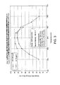
- Figure 3 is a graph showing the results of an experiment comparing the NOx storage and conversion efficiency of a one-inch core of a NOx trap uniformly loaded at 70 gpcf Pt/Rh with two half-inch cores of the same formulation where the front half is loaded at 40 gpcf Pt/Rh and the back half is loaded at 100 gpcf Pt/Rh ("the 40/100 system").
- the measurements were made on a 60 second lean/5 second rich cycle. These tests were performed at a constant space velocity of 25000 hr -1 .
- each NOx trap sample was aged for 50 hours at 800°C inlet temperature on a pulse-flame combustion reactor behind a 0.5" three-way catalyst that was aging according to a predetermined routine with a maximum temperature of 1000°C.
- 1" cores of 40 gpcf and 100 gpcf were aged separately, and then the front half of the 40 gpcf piece was tested in front of the back half of the 100 gpcf piece.
- the 40/100 system outperforms the uniformly loaded 70 gpcf loading at 400°C and below, where the precious metal concentration has a significant influence on the NOx storage performance. However, in the range of approximately 450 to 500°C, where the noble metal concentration has less influence, the performance is similar between the two systems.
- catalytic NOx storage and conversion region 114 with the higher catalytic metal concentration, is placed behind catalytic NOx storage and conversion region 12, with a lower catalytic metal concentration.
- region 114 with the higher catalytic metal concentration that helps to provide good NOx storage performance at low temperatures after aging, is protected from most of the thermal aging caused by reactions of hydrocarbons, CO and NOx on the catalytic metal during periods of stoichiometric or rich operation.
- Figure 5 compares the performance of the 40/100 system from Figure 3 with a 100/40 system in which the upstream catalytic NOx storage and conversion region has a higher concentration of catalytic metal (100 gpcf) than the downstream catalytic NOx storage and conversion region (40 gpcf).
- the measurements were performed at a constant space velocity.
- the 40/100 system outperforms the 100/40 system at 300 °C and 350°C. This improvement at low temperatures may be attributed to better retention of low temperature performance from the 100 gpcf section when it is aged in the rear position.
- the 100/40 system performs about the same as the uniform 70 gpcf system at these temperatures, and this may be attributable to the fact that the 100 gpcf zone has been aged more in the front position.
- Figure 6 compares the results of the 1.8+4.8 g/L system from Figure 3 with a corresponding 4.8+1.8 g/L system (i.e. where the upstream catalytic NOx storage and conversion region has a catalytic metal concentration of 4.8 g/L, and the downstream catalytic NOx storage and conversion region has a catalytic metal concentration of 1.8 g/L).
- the measurements of Figure 6 were taken with a linearly increasing space velocity. Again, the NOx trap with the higher concentration of catalytic metal in the downstream portion of the trap was shown to outperform the system with higher concentration of catalytic metal in the upstream portion of the trap. It should be noted that both the 1.8/4.8 and 4.8/1.8 NOx traps outperformed the uniformly loaded NOx trap.
- Figure 7 depicts, generally at 210, an exemplary NOx trap having three catalytic NOx storage and conversion regions 212, 214 and 216.
- Catalytic NOx storage and conversion region 212 has a lower catalytic metal concentration than catalytic NOx storage and conversion region 214
- region 214 has a lower catalytic metal concentration than region 216.
- Figure 8 depicts, generally at 300, an exemplary NOx trap having four catalytic NOx storage and conversion regions 312, 314, 316 and 318.
- Catalytic NOx storage and conversion region 312 has a lower catalytic metal concentration than region 314, which has a lower catalytic metal concentration than region 316, which in turn has a lower catalytic metal concentration than region 318.
- a NOx trap may have five, six, seven or more different catalytic metal regions if desired.
- the concentration of metal catalyst may increase in a continuous manner along the length of the NOx trap, as indicated graphically at 410 in Figure 9.
- variations in catalytic metal concentrations not shown in Figures 2 and 7-9 may also be used.
- the concentration of metal catalyst may increase in an exponential or logarithmic manner along the direction of emissions stream flow through the NOx trap, or may increase in a non-linear manner.
- Figures 2 and 7-9 depict NOx traps having a lower concentration of catalytic metal in an upstream region of the trap and a higher concentration of catalytic metal in a downstream region of the trap, it will be appreciated that the upstream region may have a higher concentration of catalytic metal than the downstream region. While such a configuration may not be as resistant to thermal aging as the configuration in which the upstream region has a lower concentration of catalytic metal, the experimental results summarized in Figures 5 and 6 show that such a configuration may still offer better NOx storage and conversion performance than a NOx trap with uniform loading of catalytic metal.
- reaction conditions disclosed herein are exemplary in nature, and that these specific embodiments are not to be considered in a limiting sense, because numerous variations are possible.
- the subject matter of the present disclosure includes all novel and non-obvious combinations and sub-combinations of the various catalytic metal concentrations, zoning configurations, NOx trap designs, and other aspects related to NOx traps disclosed herein.
- the following claims particularly point out certain combinations and sub-combinations regarded as novel and non-obvious. These claims may refer to "an" element or "a first" element or the equivalent thereof. Such claims should be understood to include incorporation of one or more such elements, neither requiring nor excluding two or more such elements.
- a system and method for improved control is described that takes into account axial loading of oxidants, such as NOx.
- the axial loading of NOx in the trap may be estimated during lean operation, and then the rate of excess reductants provided to the trap adjusted during rich purging operation.
- the air-fuel ratio of the exhaust gas during the purging operation may be adjusted based on various parameters to attempt to lower the amount of unreacted NOx released from the tailpipe. These parameters may include temperature, time since purging began, and a total amount of NOx or oxidants stored in the trap. However, as described herein, simply relying on the total amount of stored constituents, such as NOx, may lead to improper reductant supply. This is described more fully with regard to Figure 10.
- Figure 10 shows two examples of how NOx may be distributed axially along a catalyst brick.
- Example A has a higher total amount of NOx stored for an assumed even distribution, while example B has a lower total amount of NOx stored (where both examples are shown for a common total number of available NOx sites).
- a reductant wave-front can be considered to move along the axial length of the emission control device as described in more detail below with regard to Figure 11.
- reductant As reductant is supplied to the trap, the reductant first encounters NOx stored near the front face. Then, as more reductant is supplied, reductant gradually moves through the axial length of the catalyst, reacting with stored oxidants, until breakthrough occurs (at which time purging may be terminated). In this way, the reactions that occur in an upstream section of the catalyst affect the reactions (and the available reactants) in downstream sections of the catalyst, and so on from the front to rear of the catalyst.
- the total amount, or percent total amount, of stored oxidants may be a useful value in determining an appropriate amount of reductants
- the axial loading of oxidants may also be used to adjust the air-fuel ratio (or flow rate of reductants) so that an improved profile may be obtained.
- the engine air-fuel and/or airflow, fuel flow, etc.
- the NOx storage distribution information which may be measured, estimated, or combinations thereof.
- FIG 11 it shows an example catalyst brick 1110 that may be divided (e.g., for estimation purposes, or physically divided, if desired) into a plurality of sections.
- A-E several sample sections, A-E, are shown starting from the front face of the brick. While this example shows a single brick, it may equally apply to any number of bricks or emission control devices, or to a portion of a brick or emission control device.
- the sections show conceptually the amount of oxidants (e.g., NOx plus Oxygen) stored at different locations/sections with a horizontal line (and angled fill shading). Also, the figure shows an example location of a reductant wave-front at an example position. This illustrates how, for the given location of the wave-front, the amount of reductants available for reaction with stored oxidants may be matched to the amount stored in the section it is about to confront (e.g., section C in this example).
- the exhaust air-fuel ratio and/or mass flow rate, or exhaust constituents
- the wave-front reaches section D, even less reductant may be available.
- the wave-front reaches section E, theoretically no reductants may be available.
- the exhaust air-fuel ratio (and/or mass flow, or exhaust constituents) may be adjusted upstream (e.g., in the engine exhaust, or the exhaust upstream of brick 810) so that when the wave-front reaches section E, for example, the air-fuel ratio has returned to stoichiometry or lean, and the air-fuel ratio of the wave-front is stoichiometric or lean.
- the exhaust air-fuel ratio may be adjusted in advance of what the desired wave-front reductant amount is set to be due to transport delay, as well as any reactions that may occur upstream of the particular section.
- there are a variety of approaches for adjusting the amount and/or rate of reductants supplied to the device including changing the air-fuel ratio, changing the exhaust mass flow, changing an amount of reductant injected into the exhaust, or others.
- Such an approach, or any other described herein, may be applied to emission control devices or catalyst bricks in various positions and sizes, including devices in parallel or in series.
- the estimate of axial loading and corresponding purge control may be performed on a per bank basis if there are multiple NOx traps in separate banks, for example.
- a flow chart is illustrated for performing the determination of axial NOx and/or oxygen distribution.
- a routine is described for estimating axial loading of NOx assuming even distribution of oxygen.
- the estimated parameters may then be made available on line during engine operation to be used to advantage in controlling operation, such as engine or exhaust air-fuel ratio during purging, as well as in determining device degradation, such as engine or catalyst degradation.
- the routine divides the catalyst into sections for estimation purposes.
- the size of the sections may be constant, or vary along the length to provide higher resolution where more storage or reaction activity occurs, for example. Also, a fixed number and size of sections may also be used during all conditions, so that step 1210 may be skipped. In an alternative, the number and size of sections may vary based on other operating conditions, such as device temperature, time since engine start, catalyst degradation, and/or others.
- the routine estimates incoming reductants, incoming oxidants, stored oxidants, released oxidants, outgoing reductants, and/or outgoing oxidants.
- the constituent estimates may be based on the exhaust gas contents, or engine out constituents. Inputs to this estimate may include: temperature at each section, size of section, axial position of section (along the length of exhaust gas flow), degradation of each section (such as aging and/or sulfur contamination and removal), precious metal loading of each section, combinations thereof, and others. Further, the estimate may take into account space velocity effects on storage/purging of oxidants, such as NOx.
- the routine uses the section estimates for adjusting various engine and/or exhaust parameters. For example, the routine may use the section estimates to determine when to end lean operation and purge stored oxidants, select the air-fuel ratio during NOx purging, such as the air-fuel ratio profile(s) during purging, and/or to estimate when to terminate rich purging operation.
- the estimation may include, for each section, determining the desired amount of incoming reductants so that when the actual reductants reach that section, the right amount of incoming reductants is available for the amount of NOx and oxygen stored at that location (as well as taking into account any effects on downstream sections, or tailpipe emissions). Then, this desired amount of incoming reductants can be used to determine the desired air-fuel ratio profile in the exhaust over time, as well as other parameters, such as desired exhaust temperature, desired exhaust mass flow rate, and others.
- a routine is described for controlling engine operation based on axial information in the emission control device.
- the routine monitors an amount of NOx stored in the device, and a distribution of NOx storage along the catalyst length.
- the estimation described above may be used.
- Further additional information from upstream and/or downstream exhaust sensors may also be used to monitor NOx storage amount and location along the catalyst length.
- a NOx and/or oxygen sensor upstream, downstream, or in the emission control device can be used to improve any determinations of oxidant storage amounts and/or locations.
- the routine determines whether an amount stored/location value triggers a temporary air-fuel ratio change from lean to stoichiometric or rich to purge stored oxidants, such as NOx. For example, a weighted average of NOx stored at different axial positions may be used to trigger such operation. In an alternative embodiment, a downstream NOx sensor may be used to determine an amount of emissions per distance to trigger such operation.
- step 1314 the routine continues to maintain or return to lean or stoichiometric operation.
- the routine selects a desired exhaust air-fuel ratio value based on NOx stored, location of storage, and/or axial position of the reductant wavefront, device temperature (or temperature profile along an axial length) or combinations thereof.
- the desired exhaust air-fuel ratio may then be used to adjust engine operation (e.g., fuel injection, airflow amounts, etc.) to provide the desired air-fuel ratio.
- step 1316 determines if the NOx purge is complete by monitoring position of reductant wavefront and an amount of reductant at the wavefront. This may be done using the above estimates, as well as information from exhaust sensors upstream, downstream, or in the emission control device. For example, if an oxygen sensor is located at a given axial position, it can detect movement of a reductant wavefront based on the measured oxygen concentration. In one example, when lack of oxygen is detected (beyond a threshold, for example), the position of the reductant wavefront may be determined.
- step 1314 If the purge is incomplete, the routine returns to step 1314. If it is complete, (e.g., the wavefront has reached a selected axial position with a given strength), the routine continues to step 1318 to return to lean (or stoichiometric) operation.
- the routine may use the amount of NOx stored, and where it is stored, to control various aspects of engine and/or vehicle operation. For example, this information may be used to determine when to purge a catalyst, how long to purge a catalyst, and the level of richness and/or reductant mass flow rate of the exhaust used to purge a catalyst at different periods. Further, this information can be used to obtain improved estimates of catalyst degradation, as well as to improve desulphurization control, temperature control, or others.
- the loading e.g., Pt loading
- the number of storage sites along the length of the brick may also not be uniform. Therefore, in one example, the estimation of the NOx trap behavior may explicitly divide the brick into at least two domains, one with a lower site density per unit volume and one with a higher site density per unit volume.
- the model may be broken into more than 2 zones to account for the differential aging that takes place along the length of the brick. For example, the front of the catalyst may deteriorate faster than the back of the catalyst.
- one advantage to PGM zoning is that it allows for the increased capacity in an aged part as more sites are placed in the rear of the brick initially.
- the model can be adjusted to ensure that the sum of the capacity as a function of position equals the total capacity of the brick measured with sensors or by other methods. This may allow for accurate prediction of the amount of NOx stored on the brick as a function of time and position, which can then be used in the control strategy (e.g., such as determining the desired air-fuel ratio, desired catalyst temperature, etc.) to improve performance
- oxygen storage may still be evenly distributed across a particular catalyst (or it may be assumed to be so).
- a particular brick with a particular oxygen storage precious metal loading, it may be assumed that oxygen storage is evenly distributed across the brick, even though NOx storage varies axially.
- different bricks may have a different oxygen storage capacity, depending on the total loading in a given brick.
- variation in oxygen storage in different catalyst sections may also be included.
- a second control feature that may be used in the present disclosure can take advantage of the potentially different temperature windows between higher loaded and lower loaded zones.
- Figure 14 shows the efficiency of 4 devices with 4 different PGM loadings in a standard laboratory test after aging.
- Figure 14 shows that devices with higher PGM loading have better performance at lower temperatures, and traps with lower PGM loading have better performance at higher temperatures.
- the emission control devices may be divided into discrete sections along an axial direction, thereby enabling the ability to account for any difference in performance, such as the temperature at which NOx may desorb from the catalyst (which may depend upon the local temperature, A/F, PGM loading, and amount of NOx stored). Since one or more of these factors may change as a function of position, a discrete model in the axial direction for the NOx trap may be used to advantage.
Landscapes
- Engineering & Computer Science (AREA)
- Chemical & Material Sciences (AREA)
- Combustion & Propulsion (AREA)
- Mechanical Engineering (AREA)
- General Engineering & Computer Science (AREA)
- Chemical Kinetics & Catalysis (AREA)
- Biomedical Technology (AREA)
- Environmental & Geological Engineering (AREA)
- Analytical Chemistry (AREA)
- General Chemical & Material Sciences (AREA)
- Oil, Petroleum & Natural Gas (AREA)
- Health & Medical Sciences (AREA)
- Exhaust Gas After Treatment (AREA)
- Exhaust Gas Treatment By Means Of Catalyst (AREA)
Applications Claiming Priority (1)
| Application Number | Priority Date | Filing Date | Title |
|---|---|---|---|
| US10/985,578 US7363758B2 (en) | 2004-11-09 | 2004-11-09 | Lean burn engine control NOx purging based on positional loading of oxidants in emission control device |
Publications (2)
| Publication Number | Publication Date |
|---|---|
| EP1662124A1 true EP1662124A1 (fr) | 2006-05-31 |
| EP1662124B1 EP1662124B1 (fr) | 2010-04-07 |
Family
ID=35395596
Family Applications (1)
| Application Number | Title | Priority Date | Filing Date |
|---|---|---|---|
| EP05109651A Expired - Fee Related EP1662124B1 (fr) | 2004-11-09 | 2005-10-17 | Système de contrôle d'épuration de NOx pour moteur à mélange pauvre en fonction de la position du chargement des oxydants dans un dispositif de contrôle d'émissions |
Country Status (5)
| Country | Link |
|---|---|
| US (1) | US7363758B2 (fr) |
| EP (1) | EP1662124B1 (fr) |
| JP (1) | JP2006138322A (fr) |
| CN (1) | CN100562653C (fr) |
| DE (1) | DE602005020406D1 (fr) |
Cited By (1)
| Publication number | Priority date | Publication date | Assignee | Title |
|---|---|---|---|---|
| EP2141333A1 (fr) * | 2007-04-26 | 2010-01-06 | Honda Motor Co., Ltd. | Appareil de purification de gaz d'échappement |
Families Citing this family (11)
| Publication number | Priority date | Publication date | Assignee | Title |
|---|---|---|---|---|
| US7673445B2 (en) * | 2004-11-09 | 2010-03-09 | Ford Global Technologies, Llc | Mechanical apparatus having a catalytic NOx storage and conversion device |
| DE102005012568A1 (de) * | 2005-03-18 | 2006-09-21 | Daimlerchrysler Ag | Vorrichtung zur Entfernung von Stickoxiden aus Brennkraftmaschinenabgas und Verfahren zur Dosierung eines Zuschlagstoffs für Brennkraftmaschinenabgas |
| US7698887B2 (en) * | 2005-06-17 | 2010-04-20 | Emcon Technologies Llc | Method and apparatus for determining local emissions loading of emissions trap |
| US7831378B2 (en) * | 2007-10-30 | 2010-11-09 | Cummins Inc. | System and method for estimating NOx produced by an internal combustion engine |
| US8857159B2 (en) * | 2009-11-25 | 2014-10-14 | Gm Global Technology Operations, Inc. | Systems and methods for reducing NOx breakthrough |
| US9163575B2 (en) * | 2013-03-22 | 2015-10-20 | Ford Global Technologies, Llc | Methods and systems for an oxygen sensor |
| KR101534933B1 (ko) * | 2013-10-24 | 2015-07-07 | 현대자동차주식회사 | 차량 촉매 운용 시스템 및 방법 |
| JP6477088B2 (ja) * | 2015-03-20 | 2019-03-06 | いすゞ自動車株式会社 | NOx吸蔵量推定装置 |
| DE102016222012B4 (de) * | 2015-12-18 | 2022-09-29 | Ford Global Technologies, Llc | Verfahren zum Steuern eines NOx-Speicher-Katalysators |
| EP3840862A1 (fr) * | 2018-08-22 | 2021-06-30 | Johnson IP Holding, LLC | Convertisseur de récupération d'énergie de gaz d'échappement |
| CN111828148B (zh) * | 2019-04-15 | 2021-10-26 | 康明斯排放处理公司 | 用于检测未完成清除事件的系统和方法 |
Citations (4)
| Publication number | Priority date | Publication date | Assignee | Title |
|---|---|---|---|---|
| DE19929293A1 (de) * | 1999-06-25 | 2000-12-28 | Volkswagen Ag | Verfahren zur Steuerung einer Regeneration eines NOx-Speicherkatalysators |
| DE19929292A1 (de) * | 1999-06-25 | 2000-12-28 | Volkswagen Ag | Verfahren zur Steuerung eines Arbeitsmodus einer Verbrennungskraftmaschine |
| EP1426572A2 (fr) * | 2002-11-29 | 2004-06-09 | Toyota Jidosha Kabushiki Kaisha | Dispositif et procédé de purification de gaz d'échappement pour moteur à combustion interne |
| FR2856741A1 (fr) * | 2003-06-30 | 2004-12-31 | Renault Sa | Procede et dispositif d'estimation d'une masse d'oxydes d'azote stockee dans un dispositif de piegeage catalytique de vehicule automobile |
Family Cites Families (8)
| Publication number | Priority date | Publication date | Assignee | Title |
|---|---|---|---|---|
| JP3272464B2 (ja) * | 1992-04-23 | 2002-04-08 | マツダ株式会社 | 排気ガス浄化用触媒構造 |
| JPH06165920A (ja) * | 1992-11-30 | 1994-06-14 | Toyota Motor Corp | 排ガス浄化方法 |
| GB2313796A (en) | 1996-06-08 | 1997-12-10 | Ford Motor Co | Catalytic converter for a lean burn engine |
| JPH108950A (ja) * | 1996-06-28 | 1998-01-13 | Denso Corp | 内燃機関の排ガス浄化装置 |
| US6336320B1 (en) * | 1998-07-10 | 2002-01-08 | Toyota Jidosha Kabushiki Kaisha | Exhaust gas purification device for an internal combustion engine |
| DE10039708A1 (de) * | 2000-08-14 | 2002-03-07 | Bosch Gmbh Robert | Verfahren und Modell zur Modellierung einer Ausspeicherphase eines Stickoxid-Speicherkatalysators |
| US6860101B2 (en) * | 2001-10-15 | 2005-03-01 | Toyota Jidosha Kabushiki Kaisha | Exhaust gas purification system for internal combustion engine |
| JP2004162694A (ja) * | 2002-09-20 | 2004-06-10 | Mazda Motor Corp | エンジンの排気浄化装置 |
-
2004
- 2004-11-09 US US10/985,578 patent/US7363758B2/en active Active
-
2005
- 2005-10-17 DE DE602005020406T patent/DE602005020406D1/de active Active
- 2005-10-17 EP EP05109651A patent/EP1662124B1/fr not_active Expired - Fee Related
- 2005-11-01 CN CNB2005101195031A patent/CN100562653C/zh not_active Expired - Fee Related
- 2005-11-09 JP JP2005325228A patent/JP2006138322A/ja active Pending
Patent Citations (4)
| Publication number | Priority date | Publication date | Assignee | Title |
|---|---|---|---|---|
| DE19929293A1 (de) * | 1999-06-25 | 2000-12-28 | Volkswagen Ag | Verfahren zur Steuerung einer Regeneration eines NOx-Speicherkatalysators |
| DE19929292A1 (de) * | 1999-06-25 | 2000-12-28 | Volkswagen Ag | Verfahren zur Steuerung eines Arbeitsmodus einer Verbrennungskraftmaschine |
| EP1426572A2 (fr) * | 2002-11-29 | 2004-06-09 | Toyota Jidosha Kabushiki Kaisha | Dispositif et procédé de purification de gaz d'échappement pour moteur à combustion interne |
| FR2856741A1 (fr) * | 2003-06-30 | 2004-12-31 | Renault Sa | Procede et dispositif d'estimation d'une masse d'oxydes d'azote stockee dans un dispositif de piegeage catalytique de vehicule automobile |
Cited By (2)
| Publication number | Priority date | Publication date | Assignee | Title |
|---|---|---|---|---|
| EP2141333A1 (fr) * | 2007-04-26 | 2010-01-06 | Honda Motor Co., Ltd. | Appareil de purification de gaz d'échappement |
| EP2141333A4 (fr) * | 2007-04-26 | 2011-04-27 | Honda Motor Co Ltd | Appareil de purification de gaz d'échappement |
Also Published As
| Publication number | Publication date |
|---|---|
| CN100562653C (zh) | 2009-11-25 |
| CN1896468A (zh) | 2007-01-17 |
| EP1662124B1 (fr) | 2010-04-07 |
| US7363758B2 (en) | 2008-04-29 |
| JP2006138322A (ja) | 2006-06-01 |
| DE602005020406D1 (de) | 2010-05-20 |
| US20060096277A1 (en) | 2006-05-11 |
Similar Documents
| Publication | Publication Date | Title |
|---|---|---|
| EP1662124B1 (fr) | Système de contrôle d'épuration de NOx pour moteur à mélange pauvre en fonction de la position du chargement des oxydants dans un dispositif de contrôle d'émissions | |
| EP1655462B1 (fr) | Appareil mécanique avec catalyseur à accumulation et de conversion de NOx | |
| EP2119882B1 (fr) | APPAREIL POUR DIAGNOSTIQUER LA DÉTÉRIORATION D'UN CATALYSEUR DE NOx | |
| US7918086B2 (en) | System and method for determining a NOx storage capacity of catalytic device | |
| KR100593240B1 (ko) | 내연 기관의 공연비 제어 장치 | |
| US6990800B2 (en) | Diesel aftertreatment systems | |
| CN1095028C (zh) | 监控NOx存储器的方法和设备 | |
| US8713914B2 (en) | Method and apparatus for monitoring a hydrocarbon-selective catalytic reduction device | |
| US6990854B2 (en) | Active lean NOx catalyst diagnostics | |
| US20070084196A1 (en) | System and method for determining a NOx storage capacity of a catalytic device | |
| US10253673B1 (en) | Apparatus for purifying exhaust gas | |
| US10208688B2 (en) | Exhaust gas purification apparatus and method for controlling the same | |
| US10760461B2 (en) | Catalyst oxygen purge control apparatus and method | |
| CN113027580A (zh) | 催化剂劣化检测装置 | |
| CN108150251B (zh) | 废气净化装置及其控制方法 | |
| CN113175387B (zh) | 下游侧空燃比检测装置的异常诊断装置 | |
| KR20050013996A (ko) | Nox 저장 성분을 갖는 3방향 촉매를 포함하는 스파크점화 엔진 | |
| JP6988648B2 (ja) | 内燃機関の排気浄化装置 | |
| US11225896B1 (en) | Degradation diagnosis device for exhaust gas control catalyst | |
| KR20220006310A (ko) | 배출 가스 정화 장치 및 그 제어 방법 | |
| JP2004339967A (ja) | エンジンの排気ガス浄化装置 | |
| JP4277374B2 (ja) | 内燃機関の排気浄化装置 | |
| US20030070422A1 (en) | Oxidant storage capacity estimation | |
| JP5088632B2 (ja) | 触媒劣化診断装置 |
Legal Events
| Date | Code | Title | Description |
|---|---|---|---|
| PUAI | Public reference made under article 153(3) epc to a published international application that has entered the european phase |
Free format text: ORIGINAL CODE: 0009012 |
|
| AK | Designated contracting states |
Kind code of ref document: A1 Designated state(s): AT BE BG CH CY CZ DE DK EE ES FI FR GB GR HU IE IS IT LI LT LU LV MC NL PL PT RO SE SI SK TR |
|
| AX | Request for extension of the european patent |
Extension state: AL BA HR MK YU |
|
| 17P | Request for examination filed |
Effective date: 20061023 |
|
| 17Q | First examination report despatched |
Effective date: 20061122 |
|
| AKX | Designation fees paid |
Designated state(s): DE FR GB |
|
| GRAP | Despatch of communication of intention to grant a patent |
Free format text: ORIGINAL CODE: EPIDOSNIGR1 |
|
| GRAS | Grant fee paid |
Free format text: ORIGINAL CODE: EPIDOSNIGR3 |
|
| GRAA | (expected) grant |
Free format text: ORIGINAL CODE: 0009210 |
|
| AK | Designated contracting states |
Kind code of ref document: B1 Designated state(s): DE FR GB |
|
| REG | Reference to a national code |
Ref country code: GB Ref legal event code: FG4D |
|
| REF | Corresponds to: |
Ref document number: 602005020406 Country of ref document: DE Date of ref document: 20100520 Kind code of ref document: P |
|
| PLBE | No opposition filed within time limit |
Free format text: ORIGINAL CODE: 0009261 |
|
| STAA | Information on the status of an ep patent application or granted ep patent |
Free format text: STATUS: NO OPPOSITION FILED WITHIN TIME LIMIT |
|
| 26N | No opposition filed |
Effective date: 20110110 |
|
| GBPC | Gb: european patent ceased through non-payment of renewal fee |
Effective date: 20101017 |
|
| PG25 | Lapsed in a contracting state [announced via postgrant information from national office to epo] |
Ref country code: FR Free format text: LAPSE BECAUSE OF NON-PAYMENT OF DUE FEES Effective date: 20101102 |
|
| REG | Reference to a national code |
Ref country code: FR Ref legal event code: ST Effective date: 20110630 |
|
| PG25 | Lapsed in a contracting state [announced via postgrant information from national office to epo] |
Ref country code: GB Free format text: LAPSE BECAUSE OF NON-PAYMENT OF DUE FEES Effective date: 20101017 |
|
| REG | Reference to a national code |
Ref country code: DE Ref legal event code: R082 Ref document number: 602005020406 Country of ref document: DE Representative=s name: DOERFLER, THOMAS, DR.-ING., DE |
|
| PGFP | Annual fee paid to national office [announced via postgrant information from national office to epo] |
Ref country code: DE Payment date: 20190917 Year of fee payment: 15 |
|
| REG | Reference to a national code |
Ref country code: DE Ref legal event code: R119 Ref document number: 602005020406 Country of ref document: DE |
|
| PG25 | Lapsed in a contracting state [announced via postgrant information from national office to epo] |
Ref country code: DE Free format text: LAPSE BECAUSE OF NON-PAYMENT OF DUE FEES Effective date: 20210501 |