EP1662068B1 - Floor and floor construction - Google Patents
Floor and floor construction Download PDFInfo
- Publication number
- EP1662068B1 EP1662068B1 EP05077539A EP05077539A EP1662068B1 EP 1662068 B1 EP1662068 B1 EP 1662068B1 EP 05077539 A EP05077539 A EP 05077539A EP 05077539 A EP05077539 A EP 05077539A EP 1662068 B1 EP1662068 B1 EP 1662068B1
- Authority
- EP
- European Patent Office
- Prior art keywords
- floor
- flanges
- supports
- tiles
- floor tiles
- Prior art date
- Legal status (The legal status is an assumption and is not a legal conclusion. Google has not performed a legal analysis and makes no representation as to the accuracy of the status listed.)
- Expired - Lifetime
Links
Images



Classifications
-
- E—FIXED CONSTRUCTIONS
- E04—BUILDING
- E04F—FINISHING WORK ON BUILDINGS, e.g. STAIRS, FLOORS
- E04F15/00—Flooring
- E04F15/02—Flooring or floor layers composed of a number of similar elements
- E04F15/06—Flooring or floor layers composed of a number of similar elements of metal, whether or not in combination with other material
-
- E—FIXED CONSTRUCTIONS
- E04—BUILDING
- E04F—FINISHING WORK ON BUILDINGS, e.g. STAIRS, FLOORS
- E04F15/00—Flooring
- E04F15/02—Flooring or floor layers composed of a number of similar elements
- E04F15/024—Sectional false floors, e.g. computer floors
- E04F15/02405—Floor panels
-
- E—FIXED CONSTRUCTIONS
- E04—BUILDING
- E04F—FINISHING WORK ON BUILDINGS, e.g. STAIRS, FLOORS
- E04F15/00—Flooring
- E04F15/02—Flooring or floor layers composed of a number of similar elements
- E04F15/024—Sectional false floors, e.g. computer floors
- E04F15/02405—Floor panels
- E04F15/02411—Floor panels with integrated feet
-
- E—FIXED CONSTRUCTIONS
- E04—BUILDING
- E04F—FINISHING WORK ON BUILDINGS, e.g. STAIRS, FLOORS
- E04F15/00—Flooring
- E04F15/02—Flooring or floor layers composed of a number of similar elements
- E04F15/024—Sectional false floors, e.g. computer floors
- E04F15/02447—Supporting structures
- E04F15/02452—Details of junctions between the supporting structures and the panels or a panel-supporting framework
Definitions
- the invention relates to a floor which is constructed from floor tiles which are supported by supports resting on a substructure, wherein the floor tiles are provided on their longitudinal edges with bent flanges which are received in the upper ends of grooves arranged in the supports such that a flange of a first floor tile and a flange of an adjacent floor tile lie in one groove.
- US-A-5 749 188 discloses a floor constructed from floor tiles which are supported by supports resting on a ground surface, wherein the floor tiles are provided on their longitudinal edges with bent flanges which are received in grooves arranged in the upper ends of the supports such that a flange of a first floor tile and a flange of an adjacent floor tile lie in one groove, wherein at least some measure of interspacing is present between flanges lying opposite each other in the groove, said floor tiles electrically conductive.
- US-A-5499476 discloses a floor and a hot constructed from floor tiles according to the preamble of claim 1 and claim 8 respectively.
- the invention has for its object to obtain a floor of the above stated type wherein, while maintaining an effective clamping of the flanges of the floor tiles in the grooves of the support, the floor can follow possible unevenness in the surface of the ground on which the support rest, while in addition the floor tiles can be arranged and removed in simple manner. Also, the invention has for its object to improve safety of such floor.
- a floor constructed from floor tiles which are supported by supports resting on a ground surface, wherein the floor tiles are provided on their longitudinal edges with bent flanges which are received in grooves arranged in the upper ends of the supports such that a flange of a first floor tile and a flange of an adjacent floor tile lie in one groove, wherein at least some measure of interspacing is present between flanges lying opposite each other in the groove, said floor tiles electrically conductive and said supports provided with electrical conducting means which make contact with the floor tiles for electrical interconnection thereof, characterised by the electrical conducting means comprising a peripheral contact ring or contact wire arranged in the support electrically interconnecting the floor tiles.
- the tiles When a floor according to the invention is applied the tiles can follow a sloping floor surface, since the parts of the flanges lying in the grooves can, within certain limits, pivot relative to each other. Movements between the floor tiles occurring for instance as a result of temperature changes and/or stresses in the floor can further be absorbed by the space present between the floor tiles.
- the interspacing is preferably in the order of 0.4 to 1 mm, this space being found adequate for a sufficient pivoting to make it possible to follow slopes in the ground surface occurring in (office) buildings, as well as to absorb expansion of commonly occurring materials, wherein deforming of the tiles is prevented since they are always arranged without mutual contact.
- the flanges can be connected continuously along their whole length to the remaining parts of the floor tiles, so that a reliable connection is obtained between flanges and floor plates, which will prevent undesirable deformation of the flanges.
- the floor tiles are electrically conductive and the supports are provided with electrical conducting means which make contact with the floor tiles for electrical interconnection thereof.
- an electrical earthing of the floor tiles is thus obtained for the purpose of greater safety.
- the electrical conducting means preferably comprise a conductive profile, such as a metal sleeve or extrusion profile, in which the grooves are arranged.
- the flanges on the side of the floor tile are provided with scraping protrusions which are in contact with the electrical conducting means.
- the scraping protrusions also provide a clamping for a more robust fixing of the tiles in the supports.
- the supports are preferably provided with damping means, whereby vibrations from footsteps and the like are absorbed.
- the floor tiles are provided on the underside with centring protrusions which drop into centring openings in the top side of the supports. This construction is found to provide a more robust and precise fixing and positioning.
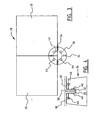
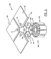
- Figures 1 and 2 show a first preferred embodiment of a kit 1 according to the present invention, comprising rectangular or square floor tiles 2 having bent flanges 4 on the edges.
- the flanges drop into grooves 6 which are arranged for this purpose in an upper outer end of support 8, with which the kit rests on a ground surface which is further not shown.
- floor tile 2 has a square form with four flanges 4 on the edges of floor tile 2 and bent at right angles relative thereto. Flanges 4 are arranged connecting to floor tile 2 along their whole length and end close to the corner points of floor tile 2.
- centring holes 10 Arranged in the upper outer end of support 8 at equal distances from each other are four centring holes 10 into which drop centring protrusions (not shown) arranged on the underside of floor tiles 2 for the purpose of positioning floor tile 2 in correct manner relative to support 8.
- electrical conducting means in a first preferred embodiment a contact ring 12 which is pressed by means of a spring construction 14 against flanges 4 for electrical interconnection thereof.
- a floor constructed from floor tiles 2 and supports 8 of kit 1 are earthed electrically on at least one floor tile. Owing to the interconnection provided by the electrical conducting means the whole floor is thus earthed for greater safety.
- a further provision is an interspace 16 which in the assembled situation is present between the edges and flanges 4 of adjacent floor tiles 2.
- This gap is preferably larger than 0.2 mm and up to for instance 2 mm, and most preferably in the order of 0.5 mm.
- flanges 4 are preferably provided on the side directed toward floor tile 2 with protrusions 18 with which the flanges are arranged clampingly in the groove 6 which in side view is diabolo-shaped.
- the gap 16 is advantageous in making the upper surfaces of floor tiles 2 sufficiently pivotable relative to each other to be able to follow slopes and other unevenness in the ground surface. Gap 16 also ensures that possible expansion of floor tiles 2, as a consequence of for instance temperature, is absorbed without deformation of the floor tiles occurring, this due to the absence of contact between the floor tiles. This pivotability is also made possible by the diabolo shape of the side walls of grooves 6 ( Fig. 2 ).
- a floor is constructed from a kit 28 comprising floor tiles 30 with bent flanges 32 on the side edges thereof as according to the above described first embodiment.
- the flanges drop into grooves 34 of supports 36.
- a gap 38 is present between floor tiles 30 and between flanges 32 which has the advantages and features in accordance with the above described gap 16.
- the flanges are further fixed clampingly by protrusions 40 into the groove 34 which in side view is diabolo-shaped ( Fig. 4 ).
- the electrical conducting means are formed in this second variant by a peripheral contact wire 42 which is arranged running around the top end of support 36 and touches the centring holes 44 therein.
- Floor tiles 30 are herein provided with threaded pins 46 which fall into centring holes 44 for the purpose of positioning the floor tiles relative to the supports and which also contact the contact wire 42 for electrical interconnection of the floor tiles.
- the floor tiles are herein manufactured from an electrically conductive material, for instance a metal or preferably galvanized steel.
- An illustrative embodiment relates to a floor constructed from a kit 50 as shown in figure 5A .
- the kit comprises floor tiles 52 having bent flanges 54 on the side edges thereof, which flanges are arranged connecting along practically the whole length to floor tiles 52.
- the bent flanges 54 drop into grooves 56 arranged in supports 58 for the purpose of supporting the floor tiles at a height relative to a ground surface 60.
- the flanges of the floor tiles are interrupted at some distance before the end of floor tile 52.
- a standing cylindrical projection 59 is arranged in the middle of support 58.
- the projection takes a form corresponding to the outer ends 55 of flanges 54, so that it acts as a stop against which the flanges of the floor tiles come to rest ( fig. 5B ).
- the projection thus also provides the correct gap between the floor tiles, preferably about 0.4 - 1 mm.
- a support 58 in this illustrative embodiment comprises a bottom mat 62 of a suitable material.
- these bottom mats 62 are approximately round and mutually connected by a grid of strips 64, which enables quicker laying of the floor.
- a support preferably comprises a roughly cylindrical steel sleeve 66 which provides the electrical interconnection of floor tiles 52 arranged therein, so that these tiles are earthed electrically despite the gap present between them.
- a cup-shaped damper 68 of an appropriate material such as plastic is arranged inside sleeve 66 for the purpose of damping shocks caused by for instance footsteps on the floor.
- Grooves 56 are arranged continuously in both sleeve 66 and damper 68.
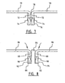
- the flanges 72 arranged on floor tiles 70 are provided in a preferred embodiment with protrusions 74 which make a scraping contact with edges 76 of a groove arranged in the support ( Fig. 7 ).
- grooves are arranged in a support, with in each case a groove 80 and a second groove 82 separated by a dividing wall 84 with a width preferably lying between about 0.4 and 1 mm ( Fig. 8 ).
- Floor tiles 86 once again have bent flanges 88 provided with protrusions 90 which come into scraping contact with walls 92, 94 of grooves 80, 82 respectively. Electrical interconnection is obtained in that floor tiles 86 and protrusions 90, as well as a part of the supports, are electrically conductive. Sufficient space is present here in grooves 80, 82 to ensure that floor tiles 86 are at least slightly pivotable relative to the support, and that (thermal) expansion of the floor tiles can also be absorbed ( Fig. 8 ).
- a floor 100 herein comprises floor tiles 102, only a fourth part of which is shown here, which floor tiles comprise on the edges bent flanges 104 which rest in groove-like recesses 106 in supports 108. Close to the corner points of floor tiles 102 centring protrusion 110 are arranged by being pressed through which drop into openings 112 arranged in the top side of supports 108.
- the supports comprise an extrusion form 114 of a suitable material such as plastic, aluminium or zamak.
- the extrusion form 114 has a practically cylindrical outer surface, and continuous openings 116 are arranged therein along the whole length which correspond with centring openings 112.
- a damper 118 is arranged on top of extrusion form 114.
- the damper is roughly cylindrical and grooves 106 are arranged therein at angles of 90° to each other, and a centring opening 112 is arranged in each case between the grooves.
- Damper 118 serves to damp shocks and is preferably manufactured from a conductive plastic which provides a correct damping and also for electrical interconnection of floor tiles 102 ( Fig. 6 ).
- Figures 9 to 12 show further possible alternative floor tiles that may be used in combination with the invention.
- Fig. 9 thus shows a practical embodiment of a floor tile 140, which in practice has sides in the order of 200 to 300 mm.
- the supports 142 are arranged with a mutual spacing in the order of 125 mm and are optionally provided with a reinforcement.
- Also shown are connecting pieces 114 for mutual connection of supports 142.
- Fig. 10 shows a tile 140 as in Fig. 9 provided with supports 142, wherein a foot connecter 144 is also shown which on the upper side has four square recesses in which the square supports 142 come to rest.
- a further foot connecter 146 is also shown wherein an earth clip 148 is arranged in the middle thereof for electrical interconnection of the supports resting on foot connecter 146 for the purpose of earthing thereof.
- Fig. 11 shows a larger floor tile 160 with sides of for instance 450 mm. Supports 162 are arranged at a mutual spacing of 150 mm.
- a larger tile 170 has for instance sides in the order of 600 mm and is arranged on a plurality of supports 172 which are arranged not only at the corner points of tile 170 but also therebetween, at a mutual distance of for instance 133 mm.
- the height of the foot is in this case the same as that of the above stated feet, but can also amount to about 55 mm.
- Such larger tiles have in the middle of the tile a support (not shown) arranged on the underside.
- the thickness of the tile is further in the order of 2 mm, just as the above mentioned tiles.
Landscapes
- Engineering & Computer Science (AREA)
- Architecture (AREA)
- Civil Engineering (AREA)
- Structural Engineering (AREA)
- General Engineering & Computer Science (AREA)
- Floor Finish (AREA)
- Body Structure For Vehicles (AREA)
Applications Claiming Priority (1)
| Application Number | Priority Date | Filing Date | Title |
|---|---|---|---|
| NL1027424A NL1027424C2 (nl) | 2004-11-04 | 2004-11-04 | Vloer en samenstel. |
Publications (2)
| Publication Number | Publication Date |
|---|---|
| EP1662068A1 EP1662068A1 (en) | 2006-05-31 |
| EP1662068B1 true EP1662068B1 (en) | 2009-08-12 |
Family
ID=34974496
Family Applications (1)
| Application Number | Title | Priority Date | Filing Date |
|---|---|---|---|
| EP05077539A Expired - Lifetime EP1662068B1 (en) | 2004-11-04 | 2005-11-04 | Floor and floor construction |
Country Status (5)
| Country | Link |
|---|---|
| EP (1) | EP1662068B1 (da) |
| AT (1) | ATE439490T1 (da) |
| DE (1) | DE602005015928D1 (da) |
| DK (1) | DK1662068T3 (da) |
| NL (1) | NL1027424C2 (da) |
Families Citing this family (2)
| Publication number | Priority date | Publication date | Assignee | Title |
|---|---|---|---|---|
| RU2017122976A (ru) * | 2014-12-02 | 2019-01-09 | Филипс Лайтинг Холдинг Б.В. | Твердотельный напольный осветительный блок и система |
| US11428015B2 (en) | 2020-09-03 | 2022-08-30 | Wearwell, Llc | Modular platform system and method of assembly |
Family Cites Families (8)
| Publication number | Priority date | Publication date | Assignee | Title |
|---|---|---|---|---|
| FR2501758A1 (fr) * | 1981-03-13 | 1982-09-17 | Plaquettes Indles Sa | Dalle metallique pour revetement de murs et plafonds. |
| FR2642782B1 (fr) * | 1989-02-03 | 1993-02-26 | Ducroux Alain | Structure de plancher, notamment pour des locaux pourvus d'un equipement informatique |
| FR2703385B1 (fr) * | 1993-03-31 | 1995-06-16 | Belbenoit Maurice | Dispositif de montage des dalles d'un plancher surélevé sur des supports verticaux. |
| US5749188A (en) * | 1993-03-31 | 1998-05-12 | Belbenoit; Maurice | Raised floor with modular slabs |
| US5499476A (en) * | 1993-08-31 | 1996-03-19 | Interface, Inc. | Low profile raised panel flooring with metal support structure |
| GB2330595B (en) * | 1996-07-31 | 2001-03-14 | Kyodo Ky Tec Corp | Floor panel including support portions and method of laying the same |
| EP1143083A1 (de) * | 2000-03-31 | 2001-10-10 | Martin Lange | Formplattenverbund aus Formplatten und Auflagemodulen und Arbeitsverfahren zur Herstellung eines solchen |
| FR2813906B1 (fr) * | 2000-09-12 | 2003-08-15 | Infra Sa | Plancher technique |
-
2004
- 2004-11-04 NL NL1027424A patent/NL1027424C2/nl not_active IP Right Cessation
-
2005
- 2005-11-04 EP EP05077539A patent/EP1662068B1/en not_active Expired - Lifetime
- 2005-11-04 AT AT05077539T patent/ATE439490T1/de active
- 2005-11-04 DE DE602005015928T patent/DE602005015928D1/de not_active Expired - Lifetime
- 2005-11-04 DK DK05077539T patent/DK1662068T3/da active
Also Published As
| Publication number | Publication date |
|---|---|
| EP1662068A1 (en) | 2006-05-31 |
| DK1662068T3 (da) | 2009-10-26 |
| DE602005015928D1 (de) | 2009-09-24 |
| NL1027424C2 (nl) | 2006-05-08 |
| ATE439490T1 (de) | 2009-08-15 |
Similar Documents
| Publication | Publication Date | Title |
|---|---|---|
| RU2116412C1 (ru) | Приподнятый панельный пол низкого профиля с металлической опорной конструкцией | |
| US12448787B2 (en) | Paver supporting apparatus | |
| US4338994A (en) | Modular panel heater having improved holder devices | |
| CN102317553B (zh) | 模块式地板系统 | |
| EP0175014B1 (en) | Apparatus for laying tile | |
| US4982539A (en) | Grid girder for raised floors | |
| KR100243400B1 (ko) | 온돌바닥용 배관구조체 | |
| WO1998004795A1 (en) | Floor panel having support and construction method therefor | |
| WO2004111544A1 (en) | Indoor floor heating system | |
| EP1662068B1 (en) | Floor and floor construction | |
| CN112443121A (zh) | 用于架空地板的底座/支架 | |
| US20140144092A1 (en) | System and apparatus for installation of tile floor | |
| KR100698848B1 (ko) | 바닥패널 | |
| GB2485181A (en) | An insulation panel support member | |
| GB2188955A (en) | Base plates for pedestals of access type raised floor | |
| KR100983131B1 (ko) | 온돌용 패널 어셈블리 구조 | |
| EP0296238A1 (en) | A floor covering of electrically conducting type | |
| WO2003066995A1 (en) | Flooring system | |
| CN100439626C (zh) | 电热地板加热系统 | |
| EP0806614B1 (en) | A plate suitable for fixing a floor heating hose | |
| GB2402405A (en) | Stackable batten support | |
| KR200339209Y1 (ko) | 온돌패널구조 | |
| KR20020060915A (ko) | 난방배관용 방음 판넬 | |
| KR100213561B1 (ko) | 건축용 합성데크플레이트 | |
| KR20190085210A (ko) | 이격판이 구비된 온돌난방 및 그 시공방법 |
Legal Events
| Date | Code | Title | Description |
|---|---|---|---|
| PUAI | Public reference made under article 153(3) epc to a published international application that has entered the european phase |
Free format text: ORIGINAL CODE: 0009012 |
|
| AK | Designated contracting states |
Kind code of ref document: A1 Designated state(s): AT BE BG CH CY CZ DE DK EE ES FI FR GB GR HU IE IS IT LI LT LU LV MC NL PL PT RO SE SI SK TR |
|
| AX | Request for extension of the european patent |
Extension state: AL BA HR MK YU |
|
| 17P | Request for examination filed |
Effective date: 20061129 |
|
| 17Q | First examination report despatched |
Effective date: 20061229 |
|
| AKX | Designation fees paid |
Designated state(s): AT BE BG CH CY CZ DE DK EE ES FI FR GB GR HU IE IS IT LI LT LU LV MC NL PL PT RO SE SI SK TR |
|
| AXX | Extension fees paid |
Extension state: HR Payment date: 20061129 Extension state: YU Payment date: 20061129 Extension state: AL Payment date: 20061129 Extension state: MK Payment date: 20061129 Extension state: BA Payment date: 20061129 |
|
| GRAP | Despatch of communication of intention to grant a patent |
Free format text: ORIGINAL CODE: EPIDOSNIGR1 |
|
| GRAS | Grant fee paid |
Free format text: ORIGINAL CODE: EPIDOSNIGR3 |
|
| GRAA | (expected) grant |
Free format text: ORIGINAL CODE: 0009210 |
|
| AK | Designated contracting states |
Kind code of ref document: B1 Designated state(s): AT BE BG CH CY CZ DE DK EE ES FI FR GB GR HU IE IS IT LI LT LU LV MC NL PL PT RO SE SI SK TR |
|
| AX | Request for extension of the european patent |
Extension state: AL BA HR MK YU |
|
| REG | Reference to a national code |
Ref country code: GB Ref legal event code: FG4D |
|
| REG | Reference to a national code |
Ref country code: CH Ref legal event code: EP |
|
| REG | Reference to a national code |
Ref country code: IE Ref legal event code: FG4D |
|
| REF | Corresponds to: |
Ref document number: 602005015928 Country of ref document: DE Date of ref document: 20090924 Kind code of ref document: P |
|
| REG | Reference to a national code |
Ref country code: DK Ref legal event code: T3 |
|
| LTIE | Lt: invalidation of european patent or patent extension |
Effective date: 20090812 |
|
| PG25 | Lapsed in a contracting state [announced via postgrant information from national office to epo] |
Ref country code: FI Free format text: LAPSE BECAUSE OF FAILURE TO SUBMIT A TRANSLATION OF THE DESCRIPTION OR TO PAY THE FEE WITHIN THE PRESCRIBED TIME-LIMIT Effective date: 20090812 Ref country code: SE Free format text: LAPSE BECAUSE OF FAILURE TO SUBMIT A TRANSLATION OF THE DESCRIPTION OR TO PAY THE FEE WITHIN THE PRESCRIBED TIME-LIMIT Effective date: 20090812 Ref country code: LT Free format text: LAPSE BECAUSE OF FAILURE TO SUBMIT A TRANSLATION OF THE DESCRIPTION OR TO PAY THE FEE WITHIN THE PRESCRIBED TIME-LIMIT Effective date: 20090812 Ref country code: ES Free format text: LAPSE BECAUSE OF FAILURE TO SUBMIT A TRANSLATION OF THE DESCRIPTION OR TO PAY THE FEE WITHIN THE PRESCRIBED TIME-LIMIT Effective date: 20091123 Ref country code: IS Free format text: LAPSE BECAUSE OF FAILURE TO SUBMIT A TRANSLATION OF THE DESCRIPTION OR TO PAY THE FEE WITHIN THE PRESCRIBED TIME-LIMIT Effective date: 20091212 |
|
| PG25 | Lapsed in a contracting state [announced via postgrant information from national office to epo] |
Ref country code: LV Free format text: LAPSE BECAUSE OF FAILURE TO SUBMIT A TRANSLATION OF THE DESCRIPTION OR TO PAY THE FEE WITHIN THE PRESCRIBED TIME-LIMIT Effective date: 20090812 Ref country code: SI Free format text: LAPSE BECAUSE OF FAILURE TO SUBMIT A TRANSLATION OF THE DESCRIPTION OR TO PAY THE FEE WITHIN THE PRESCRIBED TIME-LIMIT Effective date: 20090812 Ref country code: PL Free format text: LAPSE BECAUSE OF FAILURE TO SUBMIT A TRANSLATION OF THE DESCRIPTION OR TO PAY THE FEE WITHIN THE PRESCRIBED TIME-LIMIT Effective date: 20090812 |
|
| PG25 | Lapsed in a contracting state [announced via postgrant information from national office to epo] |
Ref country code: PT Free format text: LAPSE BECAUSE OF FAILURE TO SUBMIT A TRANSLATION OF THE DESCRIPTION OR TO PAY THE FEE WITHIN THE PRESCRIBED TIME-LIMIT Effective date: 20091212 Ref country code: BG Free format text: LAPSE BECAUSE OF FAILURE TO SUBMIT A TRANSLATION OF THE DESCRIPTION OR TO PAY THE FEE WITHIN THE PRESCRIBED TIME-LIMIT Effective date: 20091112 |
|
| PG25 | Lapsed in a contracting state [announced via postgrant information from national office to epo] |
Ref country code: EE Free format text: LAPSE BECAUSE OF FAILURE TO SUBMIT A TRANSLATION OF THE DESCRIPTION OR TO PAY THE FEE WITHIN THE PRESCRIBED TIME-LIMIT Effective date: 20090812 Ref country code: CZ Free format text: LAPSE BECAUSE OF FAILURE TO SUBMIT A TRANSLATION OF THE DESCRIPTION OR TO PAY THE FEE WITHIN THE PRESCRIBED TIME-LIMIT Effective date: 20090812 Ref country code: RO Free format text: LAPSE BECAUSE OF FAILURE TO SUBMIT A TRANSLATION OF THE DESCRIPTION OR TO PAY THE FEE WITHIN THE PRESCRIBED TIME-LIMIT Effective date: 20090812 |
|
| PG25 | Lapsed in a contracting state [announced via postgrant information from national office to epo] |
Ref country code: SK Free format text: LAPSE BECAUSE OF FAILURE TO SUBMIT A TRANSLATION OF THE DESCRIPTION OR TO PAY THE FEE WITHIN THE PRESCRIBED TIME-LIMIT Effective date: 20090812 |
|
| PLBE | No opposition filed within time limit |
Free format text: ORIGINAL CODE: 0009261 |
|
| STAA | Information on the status of an ep patent application or granted ep patent |
Free format text: STATUS: NO OPPOSITION FILED WITHIN TIME LIMIT |
|
| PG25 | Lapsed in a contracting state [announced via postgrant information from national office to epo] |
Ref country code: MC Free format text: LAPSE BECAUSE OF NON-PAYMENT OF DUE FEES Effective date: 20091130 |
|
| REG | Reference to a national code |
Ref country code: CH Ref legal event code: PL |
|
| 26N | No opposition filed |
Effective date: 20100517 |
|
| PG25 | Lapsed in a contracting state [announced via postgrant information from national office to epo] |
Ref country code: CH Free format text: LAPSE BECAUSE OF NON-PAYMENT OF DUE FEES Effective date: 20091130 Ref country code: LI Free format text: LAPSE BECAUSE OF NON-PAYMENT OF DUE FEES Effective date: 20091130 Ref country code: IE Free format text: LAPSE BECAUSE OF NON-PAYMENT OF DUE FEES Effective date: 20091104 Ref country code: GR Free format text: LAPSE BECAUSE OF FAILURE TO SUBMIT A TRANSLATION OF THE DESCRIPTION OR TO PAY THE FEE WITHIN THE PRESCRIBED TIME-LIMIT Effective date: 20091113 |
|
| PG25 | Lapsed in a contracting state [announced via postgrant information from national office to epo] |
Ref country code: LU Free format text: LAPSE BECAUSE OF NON-PAYMENT OF DUE FEES Effective date: 20091104 |
|
| PG25 | Lapsed in a contracting state [announced via postgrant information from national office to epo] |
Ref country code: HU Free format text: LAPSE BECAUSE OF FAILURE TO SUBMIT A TRANSLATION OF THE DESCRIPTION OR TO PAY THE FEE WITHIN THE PRESCRIBED TIME-LIMIT Effective date: 20100213 |
|
| PG25 | Lapsed in a contracting state [announced via postgrant information from national office to epo] |
Ref country code: TR Free format text: LAPSE BECAUSE OF FAILURE TO SUBMIT A TRANSLATION OF THE DESCRIPTION OR TO PAY THE FEE WITHIN THE PRESCRIBED TIME-LIMIT Effective date: 20090812 |
|
| PG25 | Lapsed in a contracting state [announced via postgrant information from national office to epo] |
Ref country code: CY Free format text: LAPSE BECAUSE OF FAILURE TO SUBMIT A TRANSLATION OF THE DESCRIPTION OR TO PAY THE FEE WITHIN THE PRESCRIBED TIME-LIMIT Effective date: 20090812 |
|
| PGFP | Annual fee paid to national office [announced via postgrant information from national office to epo] |
Ref country code: DK Payment date: 20131129 Year of fee payment: 9 |
|
| PGFP | Annual fee paid to national office [announced via postgrant information from national office to epo] |
Ref country code: AT Payment date: 20131126 Year of fee payment: 9 Ref country code: DE Payment date: 20131128 Year of fee payment: 9 Ref country code: GB Payment date: 20131128 Year of fee payment: 9 |
|
| PGFP | Annual fee paid to national office [announced via postgrant information from national office to epo] |
Ref country code: BE Payment date: 20131127 Year of fee payment: 9 Ref country code: NL Payment date: 20131129 Year of fee payment: 9 Ref country code: IT Payment date: 20131126 Year of fee payment: 9 Ref country code: FR Payment date: 20131125 Year of fee payment: 9 |
|
| REG | Reference to a national code |
Ref country code: DE Ref legal event code: R119 Ref document number: 602005015928 Country of ref document: DE |
|
| REG | Reference to a national code |
Ref country code: NL Ref legal event code: V1 Effective date: 20150601 |
|
| REG | Reference to a national code |
Ref country code: DK Ref legal event code: EBP Effective date: 20141130 |
|
| PG25 | Lapsed in a contracting state [announced via postgrant information from national office to epo] |
Ref country code: BE Free format text: LAPSE BECAUSE OF NON-PAYMENT OF DUE FEES Effective date: 20141130 |
|
| REG | Reference to a national code |
Ref country code: AT Ref legal event code: MM01 Ref document number: 439490 Country of ref document: AT Kind code of ref document: T Effective date: 20141104 |
|
| GBPC | Gb: european patent ceased through non-payment of renewal fee |
Effective date: 20141104 |
|
| REG | Reference to a national code |
Ref country code: FR Ref legal event code: ST Effective date: 20150731 |
|
| PG25 | Lapsed in a contracting state [announced via postgrant information from national office to epo] |
Ref country code: NL Free format text: LAPSE BECAUSE OF NON-PAYMENT OF DUE FEES Effective date: 20150601 Ref country code: AT Free format text: LAPSE BECAUSE OF NON-PAYMENT OF DUE FEES Effective date: 20141104 |
|
| PG25 | Lapsed in a contracting state [announced via postgrant information from national office to epo] |
Ref country code: DK Free format text: LAPSE BECAUSE OF NON-PAYMENT OF DUE FEES Effective date: 20141130 Ref country code: GB Free format text: LAPSE BECAUSE OF NON-PAYMENT OF DUE FEES Effective date: 20141104 Ref country code: DE Free format text: LAPSE BECAUSE OF NON-PAYMENT OF DUE FEES Effective date: 20150602 |
|
| PG25 | Lapsed in a contracting state [announced via postgrant information from national office to epo] |
Ref country code: FR Free format text: LAPSE BECAUSE OF NON-PAYMENT OF DUE FEES Effective date: 20141201 |
|
| PG25 | Lapsed in a contracting state [announced via postgrant information from national office to epo] |
Ref country code: IT Free format text: LAPSE BECAUSE OF NON-PAYMENT OF DUE FEES Effective date: 20141104 |