EP0175014B1 - Apparatus for laying tile - Google Patents
Apparatus for laying tile Download PDFInfo
- Publication number
- EP0175014B1 EP0175014B1 EP84111224A EP84111224A EP0175014B1 EP 0175014 B1 EP0175014 B1 EP 0175014B1 EP 84111224 A EP84111224 A EP 84111224A EP 84111224 A EP84111224 A EP 84111224A EP 0175014 B1 EP0175014 B1 EP 0175014B1
- Authority
- EP
- European Patent Office
- Prior art keywords
- tile
- spacer member
- cross
- groove
- support portion
- Prior art date
- Legal status (The legal status is an assumption and is not a legal conclusion. Google has not performed a legal analysis and makes no representation as to the accuracy of the status listed.)
- Expired
Links
Images


Classifications
-
- E—FIXED CONSTRUCTIONS
- E04—BUILDING
- E04F—FINISHING WORK ON BUILDINGS, e.g. STAIRS, FLOORS
- E04F15/00—Flooring
- E04F15/02—Flooring or floor layers composed of a number of similar elements
- E04F15/08—Flooring or floor layers composed of a number of similar elements only of stone or stone-like material, e.g. ceramics, concrete; of glass or with a top layer of stone or stone-like material, e.g. ceramics, concrete or glass
-
- E—FIXED CONSTRUCTIONS
- E04—BUILDING
- E04F—FINISHING WORK ON BUILDINGS, e.g. STAIRS, FLOORS
- E04F13/00—Coverings or linings, e.g. for walls or ceilings
- E04F13/07—Coverings or linings, e.g. for walls or ceilings composed of covering or lining elements; Sub-structures therefor; Fastening means therefor
- E04F13/08—Coverings or linings, e.g. for walls or ceilings composed of covering or lining elements; Sub-structures therefor; Fastening means therefor composed of a plurality of similar covering or lining elements
- E04F13/0885—Coverings or linings, e.g. for walls or ceilings composed of covering or lining elements; Sub-structures therefor; Fastening means therefor composed of a plurality of similar covering or lining elements specially adapted for being adhesively fixed to the wall; Fastening means therefor; Fixing by means of plastics materials hardening after application
-
- E—FIXED CONSTRUCTIONS
- E04—BUILDING
- E04F—FINISHING WORK ON BUILDINGS, e.g. STAIRS, FLOORS
- E04F13/00—Coverings or linings, e.g. for walls or ceilings
- E04F13/07—Coverings or linings, e.g. for walls or ceilings composed of covering or lining elements; Sub-structures therefor; Fastening means therefor
- E04F13/08—Coverings or linings, e.g. for walls or ceilings composed of covering or lining elements; Sub-structures therefor; Fastening means therefor composed of a plurality of similar covering or lining elements
- E04F13/0889—Coverings or linings, e.g. for walls or ceilings composed of covering or lining elements; Sub-structures therefor; Fastening means therefor composed of a plurality of similar covering or lining elements characterised by the joints between neighbouring elements, e.g. with joint fillings or with tongue and groove connections
- E04F13/0892—Coverings or linings, e.g. for walls or ceilings composed of covering or lining elements; Sub-structures therefor; Fastening means therefor composed of a plurality of similar covering or lining elements characterised by the joints between neighbouring elements, e.g. with joint fillings or with tongue and groove connections with means for aligning the outer surfaces of the covering elements
-
- E—FIXED CONSTRUCTIONS
- E04—BUILDING
- E04F—FINISHING WORK ON BUILDINGS, e.g. STAIRS, FLOORS
- E04F15/00—Flooring
- E04F15/02—Flooring or floor layers composed of a number of similar elements
- E04F15/02005—Construction of joints, e.g. dividing strips
- E04F15/02022—Construction of joints, e.g. dividing strips with means for aligning the outer surfaces of the flooring elements
-
- E—FIXED CONSTRUCTIONS
- E04—BUILDING
- E04F—FINISHING WORK ON BUILDINGS, e.g. STAIRS, FLOORS
- E04F15/00—Flooring
- E04F15/02—Flooring or floor layers composed of a number of similar elements
- E04F15/0215—Flooring or floor layers composed of a number of similar elements specially adapted for being adhesively fixed to an underlayer; Fastening means therefor; Fixing by means of plastics materials hardening after application
-
- E—FIXED CONSTRUCTIONS
- E04—BUILDING
- E04F—FINISHING WORK ON BUILDINGS, e.g. STAIRS, FLOORS
- E04F15/00—Flooring
- E04F15/02—Flooring or floor layers composed of a number of similar elements
- E04F15/02044—Separate elements for fastening to an underlayer
- E04F2015/02105—Separate elements for fastening to an underlayer without load-supporting elongated furring elements between the flooring elements and the underlayer
- E04F2015/02111—Separate elements for fastening to an underlayer without load-supporting elongated furring elements between the flooring elements and the underlayer not adjustable
-
- Y—GENERAL TAGGING OF NEW TECHNOLOGICAL DEVELOPMENTS; GENERAL TAGGING OF CROSS-SECTIONAL TECHNOLOGIES SPANNING OVER SEVERAL SECTIONS OF THE IPC; TECHNICAL SUBJECTS COVERED BY FORMER USPC CROSS-REFERENCE ART COLLECTIONS [XRACs] AND DIGESTS
- Y10—TECHNICAL SUBJECTS COVERED BY FORMER USPC
- Y10T—TECHNICAL SUBJECTS COVERED BY FORMER US CLASSIFICATION
- Y10T428/00—Stock material or miscellaneous articles
- Y10T428/16—Two dimensionally sectional layer
- Y10T428/163—Next to unitary web or sheet of equal or greater extent
- Y10T428/164—Continuous two dimensionally sectional layer
- Y10T428/166—Glass, ceramic, or metal sections [e.g., floor or wall tile, etc.]
-
- Y—GENERAL TAGGING OF NEW TECHNOLOGICAL DEVELOPMENTS; GENERAL TAGGING OF CROSS-SECTIONAL TECHNOLOGIES SPANNING OVER SEVERAL SECTIONS OF THE IPC; TECHNICAL SUBJECTS COVERED BY FORMER USPC CROSS-REFERENCE ART COLLECTIONS [XRACs] AND DIGESTS
- Y10—TECHNICAL SUBJECTS COVERED BY FORMER USPC
- Y10T—TECHNICAL SUBJECTS COVERED BY FORMER US CLASSIFICATION
- Y10T428/00—Stock material or miscellaneous articles
- Y10T428/24—Structurally defined web or sheet [e.g., overall dimension, etc.]
- Y10T428/24777—Edge feature
Definitions
- This invention relates to apparatus for use in constructing a surface from a plurality of tiles, comprising:
- one half of the body of said spacer members being securely affixed to each indentation in adjoining sides of said polygonal tile making up 50% of the sides of the tile
- each spacer member having its flange resting against the adjacent side of said tile.
- each spacer member is formed by a square-shaped metallic plate subdivided into two halfs by a central rectangular flange, each of the two halfs of said plate extend into opposed aligned and correspondingly shaped recesses on adjacent tiles and are secured to each tile by means of an adhesive, such as an epoxy resin.
- Said apparatus is suitable for use in manufacturing an integrated panel including a plurality of tiles made of molded ceramic material, which are preassembled in the factory, said panel forming a rigid prefabricated unit which can be handled and installed as a structural unit.
- Said apparatus would not be suitable for constructing in situ a surface from a plurality of discrete tiles made of natural stones, such as marble or granite, bonded to a bed of mortar.
- GB-A-1 350 754 also describes an apparatus of the above mentioned type.
- a glazed or unglazed ceramic tile is shown having two recesses on each of the side edges of the back face of the tile, said recesses being narrower at the edge of the tile.
- Spacer members made of moulded plastics are provided, each spacer member comprising a strip having two dual projections which fit into the recesses of adjacent tiles and each strip is attached to the edges of the tiles by means of an adhesive.
- the object of the invention is to provide an apparatus of the above mentioned type which does not require the use of an adhesive for attaching the spacer members to the tiles and enables the construction in situ of a surface from a plurality of tiles made of natural stones, such as marble or granite, bonded to a bed of mortar.
- a tile surface 52 is constituted by rectangular tiles 52, for example of marble, applied to a supporting surface with the interposition of a bed of cement mortar.
- Each tile 52 as illustrated in detail in Fig. 4, has a polished front face 52a and a rear face 52b which is roughened to facilitate its anchorage to the bed of cement.
- each tile 52 has two elongate grooves 53 in correspondence with each of its edges 52c, the grooves extending for a short distance towards the middle of this face in a direction perpendicular to each edge.
- Each groove 53 has a dovetail profile and the distance X between the bottom of each groove and the front face 52a of the tile is exactly the same for all the grooves.
- Spacer members 54 are fitted into those grooves 53 which open into two adjacent sides of each tile 52.
- the spacer members When, for example, hexagonal tiles are used instead of the rectangular tiles 52, the spacer members would be fitted into grooves formed in three consecutive sides of each tile.
- Each space member 54 is preferably constituted by a piece of plastics material of high strength, for example, nylon or polystyrene, molded in the form of an elongate body including an attachment portion 55 and a support portion 56 which are aligned with each other.
- Each of the portions 55, 56 of the spacer member 54 has a length slightly less than the length of the grooves 53.
- each spacer member 54 is constituted by a profiled section of trapezoidal cross-section corresponding to the dovetail cross-section of each of the grooves 53 in which this part is intended to be inserted by axial forcing as indicated by the arrow F in Fig. 4.
- the portion 55 is preferably wedge shaped.
- each spacer member 54 is constituted by a profiled section having a trapezoidal shape similar to that of the portion 55, but narrower than this profiled section, so that its cross-sectional area is about 40 per cent less than the cross-sectional areas of the groove 53.
- the greatest width A of the profiled section 56 is less than the width B of the opening into the groove 53.
- the support portion 56 projects from the tile 52 and has a longitudinal support surface 56a, the distance of which from the front face 52a of the tile 52 is equal to the distance X between the face 52a and the bottom of each groove 53.
- the support portion 56 has a rectangular flange 57 projecting at 90° from its end adjacent the attachment portion 55.
- each spacer member 54 has an elongate aperture 58 extending between its base faces, and the supporting portion 56 has a similar elongate aperture 59 between its base faces and a groove 60 in its end face.
- the groove 60 which has a width substantially equal to that of the aperture 59, extends across the end face of the portion 55 in a direction perpendicular to the base faces of the portion 55.
- a bed of cement mortar 61 is applied to a support surface 62 (Fig. 7).
- a second tile 52 is then placed alongside the first tile so that the bottom surfaces of two of its grooves 53 bear on the support surfaces 56a of the support portions 56 of two spacer members 54 which project from the first tile 52.
- the aperture 59 and the groove 60 of the support portion 56 are used to connect an anchoring element of metal rod to the portion 56, the element having a straight portion 63 and two end portions 64, 65 bent at 180° in opposite directions.
- One end of the anchoring element is introduced through the elongate aperture 59 and its bent portion 64 is housed in the groove 60.
- the other bent end 65 of the anchoring element is located in a hole W formed in the support wall 62 and fixed in this hole by means of cement mortar.
- a device for forming a surface made of tiles 52, which uses the same concept as the device illustrated in Figures 1 to 9 with a different form of grooves and anchoring elements.
- This device is intended particularly for use with tiles of materials (such as granite) which, because of their physical characteristics, it would not be convenient to form with the dovetail shaped grooves.
- each groove 153 has, in cross-section, a first part 66 of rectangular profile and a narrow bottom part 67 of circular profile with an extent of greater than 180° whereby it has a narrow opening and forms an undercut cavity.
- Each spacer member 154 has an attachment portion 155 constituted by a profiled section with a cross-section the same as that of the groove 153 and comprising a parallelepiped portion 68 and a cylindrical portion 69.
- the support portion 156 is provided with a rectangular flange 157 and is constituted by a profiled section having, in cross-section, a substantially circular profile similar to the profile of the part 67 of the groove 153 but narrower in that its diameter C is less than the width B of the narrow opening of the part 67.
- the support surface 156a of the profiled section 156 engages the bottom of the part 67 of the groove 153 of a second tile bearing against an edge of a first tile in which the attachment portions 155 of the spacers 154 have been force-fitted.
- the surface 156a is located at the same level as the bottom surfaces of the grooves 17 of the first tile, whereby the coplanarity of the front faces 52a of the two tiles is again ensured in this case.
- the flanges 157 of the spacers 154 again provide the correct spacing between the adjacent faces of the two tiles.
- Fig. 15 illustrates a spacer member 154a which differs from the element 154 illustrated in Figures 10 and 11 in that the support portion 156 has an aperture 158 and a groove 160 in its end face for allowing the connection of an anchoring element of the type indicated 63, 64, 65 in Fig. 7 to this portion 156.
Description
- This invention relates to apparatus for use in constructing a surface from a plurality of tiles, comprising:
- a polygonal tile having a front face intended to form part of a decorative surface and a rear face intended to be bonded to a bed of mortar,
- said tile having a plurality of similar indentations in all of its sides, and in the rear face thereof,
- each indentation having a bottom surface parallel to the front face of each tile and the distance (X) between the bottom surface of each indentation and the front face of the tile being exactly the same,
- a plurality of spacer members each having a body and a rectangular intermediate flange projecting at 90° from said body,
- one half of the body of said spacer members being securely affixed to each indentation in adjoining sides of said polygonal tile making up 50% of the sides of the tile,
- each spacer member having its flange resting against the adjacent side of said tile.
- An apparatus of the above mentioned type is known from US-A-3 234 692. According to said document the body of each spacer member is formed by a square-shaped metallic plate subdivided into two halfs by a central rectangular flange, each of the two halfs of said plate extend into opposed aligned and correspondingly shaped recesses on adjacent tiles and are secured to each tile by means of an adhesive, such as an epoxy resin.
- Said apparatus is suitable for use in manufacturing an integrated panel including a plurality of tiles made of molded ceramic material, which are preassembled in the factory, said panel forming a rigid prefabricated unit which can be handled and installed as a structural unit. Said apparatus would not be suitable for constructing in situ a surface from a plurality of discrete tiles made of natural stones, such as marble or granite, bonded to a bed of mortar.
- GB-A-1 350 754 also describes an apparatus of the above mentioned type. In the embodiment of Figures 13 and 14 a glazed or unglazed ceramic tile is shown having two recesses on each of the side edges of the back face of the tile, said recesses being narrower at the edge of the tile. Spacer members made of moulded plastics are provided, each spacer member comprising a strip having two dual projections which fit into the recesses of adjacent tiles and each strip is attached to the edges of the tiles by means of an adhesive.
- Also said apparatus would not be suitable in the case of tiles or slabs made of natural stones.
- The object of the invention is to provide an apparatus of the above mentioned type which does not require the use of an adhesive for attaching the spacer members to the tiles and enables the construction in situ of a surface from a plurality of tiles made of natural stones, such as marble or granite, bonded to a bed of mortar.
- This object is achieved by the characteristics which constitute the subject of Claim 1.
- Further characteristics and advantages of the present invention will become apparent from the description which follows with reference to the appended drawings, provided purely by way of non-limiting example, in which:
- Fig. 1 is a partial view of a tile surface obtained by use of the apparatus of the present invention;
- Fig. 2 is an exploded rear view of the surface illustrated in Fig. 1;
- Fig. 3 is a perspective view of a spacer member according to a second embodiment of the invention;
- Fig. 4 is a partial perspective view of a tile and a spacer member in the introduction phase;
- Fig. 5 is a perspective view illustrating the spacer member inserted in the tile with an adjacent tile in the assembly phase;
- Fig. 6 is a partial plan view of Figure 5;
- Fig. 7 is a section taken on the line 7-7 of Fig. 1;
- Fig. 8 is a section taken on the line 8-8 of Fig. 7;
- Fig. 9 is a section taken on the line 9-9 of Fig. 7;
- Fig. 10 is a perspective view of a second embodiment of a spacer member according to the present invention;
- Fig. 11 is a partial perspective view of two tiles and the spacer member of Fig. 10 before assembly;.
- Fig. 12 is a section illustrating the two tiles of Fig. 11 after assembly on a supporting surface;
- Fig. 13 is a cross-sectional view taken on the line 13-13 of Fig. 12;
- Fig. 14 is a cross-sectional view taken on the line 14-14 of Fig. 12; and
- Fig. 15 is a perspective view of a variant of the spacer member illustrated in Figs. 10 and 11.
- In Fig. 1, a
tile surface 52 is constituted byrectangular tiles 52, for example of marble, applied to a supporting surface with the interposition of a bed of cement mortar. - Each
tile 52, as illustrated in detail in Fig. 4, has a polishedfront face 52a and arear face 52b which is roughened to facilitate its anchorage to the bed of cement. - As illustrated in Fig. 2, the
rear face 52b of eachtile 52 has twoelongate grooves 53 in correspondence with each of itsedges 52c, the grooves extending for a short distance towards the middle of this face in a direction perpendicular to each edge. - Each
groove 53 has a dovetail profile and the distance X between the bottom of each groove and thefront face 52a of the tile is exactly the same for all the grooves. -
Spacer members 54, illustrated in detail in Figures 3 and 4, are fitted into thosegrooves 53 which open into two adjacent sides of eachtile 52. - When, for example, hexagonal tiles are used instead of the
rectangular tiles 52, the spacer members would be fitted into grooves formed in three consecutive sides of each tile. - Each
space member 54 is preferably constituted by a piece of plastics material of high strength, for example, nylon or polystyrene, molded in the form of an elongate body including anattachment portion 55 and asupport portion 56 which are aligned with each other. - Each of the
portions spacer member 54 has a length slightly less than the length of thegrooves 53. - The
attachment portion 55 of eachspacer member 54 is constituted by a profiled section of trapezoidal cross-section corresponding to the dovetail cross-section of each of thegrooves 53 in which this part is intended to be inserted by axial forcing as indicated by the arrow F in Fig. 4. - In order to achieve a force-fit of the
portion 55 in the grooves 3, theportion 55 is preferably wedge shaped. - The
support portion 56 of eachspacer member 54 is constituted by a profiled section having a trapezoidal shape similar to that of theportion 55, but narrower than this profiled section, so that its cross-sectional area is about 40 per cent less than the cross-sectional areas of thegroove 53. - In particular, the greatest width A of the
profiled section 56 is less than the width B of the opening into thegroove 53. - As seen from Figures 5 and 6, when the
spacer member 54 is inserted in thegroove 53 of atile 52, thesupport portion 56 projects from thetile 52 and has alongitudinal support surface 56a, the distance of which from thefront face 52a of thetile 52 is equal to the distance X between theface 52a and the bottom of eachgroove 53. - The
support portion 56 has arectangular flange 57 projecting at 90° from its end adjacent theattachment portion 55. - The attachment portions of each
spacer member 54 has anelongate aperture 58 extending between its base faces, and the supportingportion 56 has a similarelongate aperture 59 between its base faces and agroove 60 in its end face. - The
groove 60, which has a width substantially equal to that of theaperture 59, extends across the end face of theportion 55 in a direction perpendicular to the base faces of theportion 55. - In order to form the
tile surface 51 illustrated in Fig. 1, a bed ofcement mortar 61 is applied to a support surface 62 (Fig. 7). - A
rectangular tile 52 having twospacer members 54 force-fitted into thegrooves 53 of each of two adjacent edges of the tile, as previously described, is then placed on the bed and the tile is pressed lightly into the desired position. - A
second tile 52 is then placed alongside the first tile so that the bottom surfaces of two of itsgrooves 53 bear on thesupport surfaces 56a of thesupport portions 56 of twospacer members 54 which project from thefirst tile 52. - As a result of this positioning of the second tile 2, its
front face 52a will lie in the same plane as the front face of the first tile and its edge will bear against theflanges 57 of the twospacers 54, whereby the second tile will be exactly parallel to the first tile and uniformly spaced from the adjacent edge of the first tile. - Successive tiles are then positioned in the same manner as described above to complete the
surface 51 which will thus be perfectly uniform. - In the construction of a vertical tile surface, as illustrated in Fig. 7, the
aperture 59 and thegroove 60 of thesupport portion 56 are used to connect an anchoring element of metal rod to theportion 56, the element having astraight portion 63 and twoend portions elongate aperture 59 and itsbent portion 64 is housed in thegroove 60. - The
other bent end 65 of the anchoring element is located in a hole W formed in thesupport wall 62 and fixed in this hole by means of cement mortar. - In the variant illustrated in Figures 10 to 14, a device is illustrated for forming a surface made of
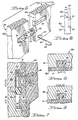
tiles 52, which uses the same concept as the device illustrated in Figures 1 to 9 with a different form of grooves and anchoring elements. - This device is intended particularly for use with tiles of materials (such as granite) which, because of their physical characteristics, it would not be convenient to form with the dovetail shaped grooves.
- According to this variant, each
groove 153 has, in cross-section, afirst part 66 of rectangular profile and anarrow bottom part 67 of circular profile with an extent of greater than 180° whereby it has a narrow opening and forms an undercut cavity. - Each
spacer member 154 has anattachment portion 155 constituted by a profiled section with a cross-section the same as that of thegroove 153 and comprising aparallelepiped portion 68 and acylindrical portion 69. Thesupport portion 156 is provided with arectangular flange 157 and is constituted by a profiled section having, in cross-section, a substantially circular profile similar to the profile of thepart 67 of thegroove 153 but narrower in that its diameter C is less than the width B of the narrow opening of thepart 67. - As is seen from Fig. 11, the
support surface 156a of the profiledsection 156 engages the bottom of thepart 67 of thegroove 153 of a second tile bearing against an edge of a first tile in which theattachment portions 155 of thespacers 154 have been force-fitted. Thesurface 156a is located at the same level as the bottom surfaces of the grooves 17 of the first tile, whereby the coplanarity of the front faces 52a of the two tiles is again ensured in this case. - Moreover, in this case, the
flanges 157 of thespacers 154 again provide the correct spacing between the adjacent faces of the two tiles. - Fig. 15 illustrates a spacer member 154a which differs from the
element 154 illustrated in Figures 10 and 11 in that thesupport portion 156 has anaperture 158 and agroove 160 in its end face for allowing the connection of an anchoring element of the type indicated 63, 64, 65 in Fig. 7 to thisportion 156.
Claims (9)
Priority Applications (4)
| Application Number | Priority Date | Filing Date | Title |
|---|---|---|---|
| US06/422,649 US4503654A (en) | 1982-09-24 | 1982-09-24 | Method and apparatus for laying tile |
| DE8484111224T DE3477031D1 (en) | 1984-09-20 | 1984-09-20 | Apparatus for laying tile |
| AT84111224T ATE41195T1 (en) | 1984-09-20 | 1984-09-20 | DEVICE FOR LAYING TILE PANELS. |
| EP84111224A EP0175014B1 (en) | 1982-09-24 | 1984-09-20 | Apparatus for laying tile |
Applications Claiming Priority (2)
| Application Number | Priority Date | Filing Date | Title |
|---|---|---|---|
| US06/422,649 US4503654A (en) | 1982-09-24 | 1982-09-24 | Method and apparatus for laying tile |
| EP84111224A EP0175014B1 (en) | 1982-09-24 | 1984-09-20 | Apparatus for laying tile |
Publications (2)
| Publication Number | Publication Date |
|---|---|
| EP0175014A1 EP0175014A1 (en) | 1986-03-26 |
| EP0175014B1 true EP0175014B1 (en) | 1989-03-08 |
Family
ID=26092201
Family Applications (1)
| Application Number | Title | Priority Date | Filing Date |
|---|---|---|---|
| EP84111224A Expired EP0175014B1 (en) | 1982-09-24 | 1984-09-20 | Apparatus for laying tile |
Country Status (2)
| Country | Link |
|---|---|
| US (1) | US4503654A (en) |
| EP (1) | EP0175014B1 (en) |
Families Citing this family (40)
| Publication number | Priority date | Publication date | Assignee | Title |
|---|---|---|---|---|
| US4620998A (en) * | 1985-02-05 | 1986-11-04 | Haresh Lalvani | Crescent-shaped polygonal tiles |
| US4953341A (en) * | 1989-08-14 | 1990-09-04 | Bob Joos | Spacers for laying tile and method of use |
| US5417050A (en) * | 1993-03-26 | 1995-05-23 | Cosentino; Edward | Tile mounting system |
| CA2066089C (en) * | 1992-04-15 | 1996-12-03 | Pietro Valente | Levelled cement spreader |
| US5362560A (en) * | 1993-05-20 | 1994-11-08 | Armstrong World Industries, Inc. | Composite tile with modified adhesive layer |
| US5603195A (en) * | 1996-04-26 | 1997-02-18 | Cosentino; Edward | Method and apparatus for laying tile |
| US6496099B2 (en) * | 1996-06-24 | 2002-12-17 | Computer Motion, Inc. | General purpose distributed operating room control system |
| WO2001012918A1 (en) * | 1999-08-17 | 2001-02-22 | Team Innovation Ltd. | Spacing of tiles |
| EP1167653B1 (en) * | 2000-06-30 | 2004-09-08 | Kronotec Ag | Method for laying floor panels |
| US6625951B1 (en) * | 2001-12-10 | 2003-09-30 | Mccarthy Lawrence | Floor laying and leveling system |
| US20030230041A1 (en) * | 2002-06-14 | 2003-12-18 | John Calderbank | Prefabricated aggregated floor panel device and system and method for making and installing aggregated panels |
| US6823640B1 (en) | 2002-07-24 | 2004-11-30 | Walter W. Pytlewski | Hollow spacer for tiles and the like |
| US7111435B2 (en) | 2002-10-23 | 2006-09-26 | Leo Flores | Tile application guides and system |
| DE20303649U1 (en) * | 2003-03-06 | 2003-07-10 | Steffens Sandra | Joint insert for building boards |
| WO2004106665A1 (en) * | 2003-06-02 | 2004-12-09 | Kenneth Harrison | Tile, tiling accessory and apparatus for dispensing adhesive for a tile |
| US20050257468A1 (en) * | 2004-05-21 | 2005-11-24 | Ron Serros | Permanent tile spacer |
| GB0503316D0 (en) * | 2005-02-17 | 2005-03-23 | Turner Intellect Property Ltd | A spacer |
| US7621100B2 (en) * | 2005-02-22 | 2009-11-24 | Davinci Italia/Usa Group, Llc | Tile alignment and leveling device and method for using the same |
| US20060260243A1 (en) * | 2005-05-03 | 2006-11-23 | Angelozzi Rocco P Jr | Planarizing panel clip and method of use |
| US7516558B2 (en) * | 2005-07-12 | 2009-04-14 | Keith Frank | Cement-based tile-setting spacers and related process |
| AU2008231348B2 (en) * | 2007-03-26 | 2011-07-21 | Q.E.P. Co., Inc. | Device for leveling and aligning tiles and method for leveling and aligning tiles |
| US7698831B2 (en) | 2008-03-19 | 2010-04-20 | Zashiki-Warashi Manufacturing Inc. | Tile spacer and holder therefor |
| US8205348B2 (en) * | 2008-03-19 | 2012-06-26 | Zashiki-Warashi Manufacturing Inc. | Tile spacer and holder therefor |
| US7946093B1 (en) * | 2008-11-07 | 2011-05-24 | Antonio Sturino | Height-adjustable tile spacers |
| US7861487B2 (en) | 2009-05-18 | 2011-01-04 | Davinci Italia/Usa Group, Llc | Tile alignment and leveling device |
| KR100932383B1 (en) * | 2009-05-25 | 2009-12-16 | 한국지질자원연구원 | Arc synthetic aperture radar system capable of acquisition of high resolution image |
| US8166726B2 (en) * | 2009-12-17 | 2012-05-01 | Dang Tuan N | Tile leveling process and apparatus |
| US20110183101A1 (en) * | 2010-01-15 | 2011-07-28 | TPS TechnoPartner Samtronic GmbH | Floor covering and method for its production |
| GB2478144A (en) * | 2010-02-26 | 2011-08-31 | Rolls Royce Plc | Panelled assembly, eg for a gas turbine engine ducted fan casing |
| US20120017528A1 (en) * | 2010-07-25 | 2012-01-26 | David Liu | Floor and tile system with pad |
| US8079199B1 (en) | 2010-08-03 | 2011-12-20 | Davinci Italia/Usa Group, Llc | Tile alignment and leveling device |
| US7954300B1 (en) | 2010-11-05 | 2011-06-07 | Davinci Italia/Usa Group, Llc | Tile alignment and leveling device |
| ITRN20110067A1 (en) * | 2011-09-19 | 2011-12-19 | Ceramica Faetano S P A | TILE CERAMIC FLOORING. |
| US8578674B2 (en) * | 2011-10-30 | 2013-11-12 | Frankie Laine Ross | Bracer spacer |
| US9945133B2 (en) | 2011-11-15 | 2018-04-17 | New Standards Manufacturing Co. | System and method for aligning and leveling tile |
| US9228363B2 (en) | 2012-03-23 | 2016-01-05 | Davinci Italia/USA Group, Inc. | Tile alignment and leveling device |
| MX352808B (en) | 2012-03-29 | 2017-12-08 | Davinci Italia/Usa Group Llc | Tile alignment and leveling device. |
| US10604945B2 (en) | 2016-09-21 | 2020-03-31 | New Standards Manufacturing Co. | Lippage control system with stretchable strap portion |
| USD854711S1 (en) * | 2017-04-05 | 2019-07-23 | Oshkosh Floor Designs Acquisition, LLC | Modular flooring tile |
| US10626624B2 (en) * | 2018-03-26 | 2020-04-21 | Liviu Leuciuc | Tile spacer and wedge tool |
Family Cites Families (8)
| Publication number | Priority date | Publication date | Assignee | Title |
|---|---|---|---|---|
| US2111003A (en) * | 1936-12-28 | 1938-03-15 | Petty Kirk Francis | Alignable tile |
| US2201129A (en) * | 1938-08-26 | 1940-05-14 | Butler Weiland Corp | Tiling |
| USRE22013E (en) * | 1938-10-25 | 1942-01-27 | Means for joining constructional | |
| FR1143592A (en) * | 1954-06-18 | 1957-10-02 | Facade coverings and means for their realization | |
| US3041785A (en) * | 1959-01-09 | 1962-07-03 | Mosaic Tile Company | Multiple unit ceramic tile assembly |
| US3234692A (en) * | 1964-01-16 | 1966-02-15 | Internat Pipe And Ceramics Cor | Tile construction |
| GB1350754A (en) * | 1970-04-21 | 1974-04-24 | British Ceramic Res Ass | Tile-fixing |
| EP0088177B1 (en) * | 1982-03-10 | 1987-02-04 | E.P.S. (Moulders) Limited | An insulation panel and a vertical and horizontal tie means for use with the panel |
-
1982
- 1982-09-24 US US06/422,649 patent/US4503654A/en not_active Expired - Fee Related
-
1984
- 1984-09-20 EP EP84111224A patent/EP0175014B1/en not_active Expired
Also Published As
| Publication number | Publication date |
|---|---|
| EP0175014A1 (en) | 1986-03-26 |
| US4503654A (en) | 1985-03-12 |
Similar Documents
| Publication | Publication Date | Title |
|---|---|---|
| EP0175014B1 (en) | Apparatus for laying tile | |
| US4571910A (en) | Apparatus for laying tile | |
| EP1395720B1 (en) | Panel, kit and method for forming a stone masonry wall | |
| US5501049A (en) | Thin brick panel assembly | |
| US4625415A (en) | Stud spacer | |
| US5373676A (en) | Thin brick panel assembly | |
| US5259161A (en) | Vertical and horizontal reinforcement and spacing guide for panels constructed of blocks | |
| AU2002302249A1 (en) | Panel, kit and method for forming a masonry wall | |
| US3234692A (en) | Tile construction | |
| US4182089A (en) | Interlocking building block | |
| US3286428A (en) | Wall of building blocks with spaced, parallel wooden panels and steel connector plates | |
| US4114337A (en) | Wasted spacer member for wall elements, especially for glass bricks | |
| US5351455A (en) | Method and apparatus for wallboard attachment | |
| US10472822B1 (en) | Insulated interlocking superblocks for constructing and supporting structural elements of a building | |
| EP0190377A1 (en) | Support plate for tiles | |
| EP1027508A1 (en) | Brick facing panel | |
| US4548008A (en) | Tile panel having convex and concave portions around substrate board, and method for production thereof | |
| US4951439A (en) | Inner wall to an outer wall in a wall construction | |
| EP0943750A2 (en) | Method of laying tile units | |
| US3850404A (en) | Tile-setting apparatus | |
| US20070012857A1 (en) | Pilaster form for an insulating concrete form building system | |
| EP1627115A1 (en) | A consumable assembly for forming a concrete wall structure, a concrete wall structure formed with the assembly and a side plate for use in the assembly | |
| EP0063550A2 (en) | Prefabricated member structure, particularly for making tile coverings | |
| JPH05156780A (en) | Composite panel and its manufacture | |
| KR0173839B1 (en) | Construction method of an insulating wall |
Legal Events
| Date | Code | Title | Description |
|---|---|---|---|
| PUAI | Public reference made under article 153(3) epc to a published international application that has entered the european phase |
Free format text: ORIGINAL CODE: 0009012 |
|
| AK | Designated contracting states |
Kind code of ref document: A1 Designated state(s): AT BE CH DE FR GB IT LI LU NL SE |
|
| 17P | Request for examination filed |
Effective date: 19860807 |
|
| 17Q | First examination report despatched |
Effective date: 19861212 |
|
| RAP3 | Party data changed (applicant data changed or rights of an application transferred) |
Owner name: COSENTINO, EDWARD |
|
| GRAA | (expected) grant |
Free format text: ORIGINAL CODE: 0009210 |
|
| AK | Designated contracting states |
Kind code of ref document: B1 Designated state(s): AT BE CH DE FR GB IT LI LU NL SE |
|
| PG25 | Lapsed in a contracting state [announced via postgrant information from national office to epo] |
Ref country code: SE Effective date: 19890308 Ref country code: NL Effective date: 19890308 Ref country code: LI Effective date: 19890308 Ref country code: CH Effective date: 19890308 Ref country code: BE Effective date: 19890308 Ref country code: AT Effective date: 19890308 |
|
| REF | Corresponds to: |
Ref document number: 41195 Country of ref document: AT Date of ref document: 19890315 Kind code of ref document: T |
|
| ITF | It: translation for a ep patent filed |
Owner name: JACOBACCI & PERANI S.P.A. |
|
| REF | Corresponds to: |
Ref document number: 3477031 Country of ref document: DE Date of ref document: 19890413 |
|
| ET | Fr: translation filed | ||
| REG | Reference to a national code |
Ref country code: CH Ref legal event code: PL |
|
| NLV1 | Nl: lapsed or annulled due to failure to fulfill the requirements of art. 29p and 29m of the patents act | ||
| PG25 | Lapsed in a contracting state [announced via postgrant information from national office to epo] |
Ref country code: LU Free format text: LAPSE BECAUSE OF NON-PAYMENT OF DUE FEES Effective date: 19890930 |
|
| PLBE | No opposition filed within time limit |
Free format text: ORIGINAL CODE: 0009261 |
|
| STAA | Information on the status of an ep patent application or granted ep patent |
Free format text: STATUS: NO OPPOSITION FILED WITHIN TIME LIMIT |
|
| 26N | No opposition filed | ||
| PGFP | Annual fee paid to national office [announced via postgrant information from national office to epo] |
Ref country code: GB Payment date: 19910913 Year of fee payment: 8 |
|
| PGFP | Annual fee paid to national office [announced via postgrant information from national office to epo] |
Ref country code: FR Payment date: 19910930 Year of fee payment: 8 Ref country code: DE Payment date: 19910930 Year of fee payment: 8 |
|
| PG25 | Lapsed in a contracting state [announced via postgrant information from national office to epo] |
Ref country code: GB Effective date: 19920920 |
|
| ITTA | It: last paid annual fee | ||
| GBPC | Gb: european patent ceased through non-payment of renewal fee |
Effective date: 19920920 |
|
| PG25 | Lapsed in a contracting state [announced via postgrant information from national office to epo] |
Ref country code: FR Effective date: 19930528 |
|
| PG25 | Lapsed in a contracting state [announced via postgrant information from national office to epo] |
Ref country code: DE Effective date: 19930602 |
|
| REG | Reference to a national code |
Ref country code: FR Ref legal event code: ST |