EP1661615A2 - Abgasbehandlungsvorrichtung - Google Patents
Abgasbehandlungsvorrichtung Download PDFInfo
- Publication number
- EP1661615A2 EP1661615A2 EP05292234A EP05292234A EP1661615A2 EP 1661615 A2 EP1661615 A2 EP 1661615A2 EP 05292234 A EP05292234 A EP 05292234A EP 05292234 A EP05292234 A EP 05292234A EP 1661615 A2 EP1661615 A2 EP 1661615A2
- Authority
- EP
- European Patent Office
- Prior art keywords
- exhaust gas
- liquid
- absorption tower
- spray header
- absorbing solution
- Prior art date
- Legal status (The legal status is an assumption and is not a legal conclusion. Google has not performed a legal analysis and makes no representation as to the accuracy of the status listed.)
- Withdrawn
Links
- 239000007788 liquid Substances 0.000 claims abstract description 94
- 238000010521 absorption reaction Methods 0.000 claims abstract description 56
- 239000007921 spray Substances 0.000 claims abstract description 53
- 238000006477 desulfuration reaction Methods 0.000 claims abstract description 10
- 230000023556 desulfurization Effects 0.000 claims abstract description 10
- 238000009434 installation Methods 0.000 claims abstract description 8
- 238000010276 construction Methods 0.000 claims description 4
- ODINCKMPIJJUCX-UHFFFAOYSA-N Calcium oxide Chemical compound [Ca]=O ODINCKMPIJJUCX-UHFFFAOYSA-N 0.000 description 8
- 238000012360 testing method Methods 0.000 description 8
- 235000019738 Limestone Nutrition 0.000 description 6
- 230000002745 absorbent Effects 0.000 description 6
- 239000002250 absorbent Substances 0.000 description 6
- 230000000694 effects Effects 0.000 description 6
- 239000006028 limestone Substances 0.000 description 6
- 239000002002 slurry Substances 0.000 description 6
- VTYYLEPIZMXCLO-UHFFFAOYSA-L Calcium carbonate Chemical compound [Ca+2].[O-]C([O-])=O VTYYLEPIZMXCLO-UHFFFAOYSA-L 0.000 description 4
- AXCZMVOFGPJBDE-UHFFFAOYSA-L calcium dihydroxide Chemical compound [OH-].[OH-].[Ca+2] AXCZMVOFGPJBDE-UHFFFAOYSA-L 0.000 description 4
- 239000000920 calcium hydroxide Substances 0.000 description 4
- 229910001861 calcium hydroxide Inorganic materials 0.000 description 4
- 239000000292 calcium oxide Substances 0.000 description 4
- 235000012255 calcium oxide Nutrition 0.000 description 4
- 230000005465 channeling Effects 0.000 description 4
- 239000010419 fine particle Substances 0.000 description 4
- 239000003595 mist Substances 0.000 description 4
- 238000007664 blowing Methods 0.000 description 3
- 230000003009 desulfurizing effect Effects 0.000 description 3
- 239000006185 dispersion Substances 0.000 description 3
- 229910000019 calcium carbonate Inorganic materials 0.000 description 2
- 235000011116 calcium hydroxide Nutrition 0.000 description 2
- 230000007423 decrease Effects 0.000 description 2
- 239000010440 gypsum Substances 0.000 description 2
- 229910052602 gypsum Inorganic materials 0.000 description 2
- 238000000034 method Methods 0.000 description 2
- 230000004048 modification Effects 0.000 description 2
- 238000012986 modification Methods 0.000 description 2
- 230000002093 peripheral effect Effects 0.000 description 2
- 238000004140 cleaning Methods 0.000 description 1
- 230000008602 contraction Effects 0.000 description 1
- 230000003993 interaction Effects 0.000 description 1
- 238000012423 maintenance Methods 0.000 description 1
- 239000000463 material Substances 0.000 description 1
- 238000012856 packing Methods 0.000 description 1
- 238000005192 partition Methods 0.000 description 1
- 238000005507 spraying Methods 0.000 description 1
- 238000012546 transfer Methods 0.000 description 1
- XLYOFNOQVPJJNP-UHFFFAOYSA-N water Substances O XLYOFNOQVPJJNP-UHFFFAOYSA-N 0.000 description 1
Images


Classifications
-
- B—PERFORMING OPERATIONS; TRANSPORTING
- B01—PHYSICAL OR CHEMICAL PROCESSES OR APPARATUS IN GENERAL
- B01D—SEPARATION
- B01D53/00—Separation of gases or vapours; Recovering vapours of volatile solvents from gases; Chemical or biological purification of waste gases, e.g. engine exhaust gases, smoke, fumes, flue gases, aerosols
- B01D53/14—Separation of gases or vapours; Recovering vapours of volatile solvents from gases; Chemical or biological purification of waste gases, e.g. engine exhaust gases, smoke, fumes, flue gases, aerosols by absorption
- B01D53/18—Absorbing units; Liquid distributors therefor
- B01D53/185—Liquid distributors
-
- E—FIXED CONSTRUCTIONS
- E02—HYDRAULIC ENGINEERING; FOUNDATIONS; SOIL SHIFTING
- E02B—HYDRAULIC ENGINEERING
- E02B3/00—Engineering works in connection with control or use of streams, rivers, coasts, or other marine sites; Sealings or joints for engineering works in general
- E02B3/04—Structures or apparatus for, or methods of, protecting banks, coasts, or harbours
- E02B3/12—Revetment of banks, dams, watercourses, or the like, e.g. the sea-floor
- E02B3/14—Preformed blocks or slabs for forming essentially continuous surfaces; Arrangements thereof
-
- A—HUMAN NECESSITIES
- A01—AGRICULTURE; FORESTRY; ANIMAL HUSBANDRY; HUNTING; TRAPPING; FISHING
- A01K—ANIMAL HUSBANDRY; AVICULTURE; APICULTURE; PISCICULTURE; FISHING; REARING OR BREEDING ANIMALS, NOT OTHERWISE PROVIDED FOR; NEW BREEDS OF ANIMALS
- A01K61/00—Culture of aquatic animals
- A01K61/10—Culture of aquatic animals of fish
-
- B—PERFORMING OPERATIONS; TRANSPORTING
- B01—PHYSICAL OR CHEMICAL PROCESSES OR APPARATUS IN GENERAL
- B01D—SEPARATION
- B01D53/00—Separation of gases or vapours; Recovering vapours of volatile solvents from gases; Chemical or biological purification of waste gases, e.g. engine exhaust gases, smoke, fumes, flue gases, aerosols
- B01D53/34—Chemical or biological purification of waste gases
- B01D53/46—Removing components of defined structure
- B01D53/48—Sulfur compounds
- B01D53/50—Sulfur oxides
- B01D53/501—Sulfur oxides by treating the gases with a solution or a suspension of an alkali or earth-alkali or ammonium compound
- B01D53/504—Sulfur oxides by treating the gases with a solution or a suspension of an alkali or earth-alkali or ammonium compound characterised by a specific device
-
- E—FIXED CONSTRUCTIONS
- E02—HYDRAULIC ENGINEERING; FOUNDATIONS; SOIL SHIFTING
- E02D—FOUNDATIONS; EXCAVATIONS; EMBANKMENTS; UNDERGROUND OR UNDERWATER STRUCTURES
- E02D29/00—Independent underground or underwater structures; Retaining walls
- E02D29/02—Retaining or protecting walls
- E02D29/0225—Retaining or protecting walls comprising retention means in the backfill
- E02D29/0241—Retaining or protecting walls comprising retention means in the backfill the retention means being reinforced earth elements
-
- E—FIXED CONSTRUCTIONS
- E02—HYDRAULIC ENGINEERING; FOUNDATIONS; SOIL SHIFTING
- E02D—FOUNDATIONS; EXCAVATIONS; EMBANKMENTS; UNDERGROUND OR UNDERWATER STRUCTURES
- E02D29/00—Independent underground or underwater structures; Retaining walls
- E02D29/02—Retaining or protecting walls
- E02D29/0258—Retaining or protecting walls characterised by constructional features
- E02D29/0266—Retaining or protecting walls characterised by constructional features made up of preformed elements
-
- B—PERFORMING OPERATIONS; TRANSPORTING
- B01—PHYSICAL OR CHEMICAL PROCESSES OR APPARATUS IN GENERAL
- B01D—SEPARATION
- B01D2251/00—Reactants
- B01D2251/40—Alkaline earth metal or magnesium compounds
- B01D2251/404—Alkaline earth metal or magnesium compounds of calcium
-
- B—PERFORMING OPERATIONS; TRANSPORTING
- B01—PHYSICAL OR CHEMICAL PROCESSES OR APPARATUS IN GENERAL
- B01D—SEPARATION
- B01D2257/00—Components to be removed
- B01D2257/30—Sulfur compounds
- B01D2257/302—Sulfur oxides
-
- E—FIXED CONSTRUCTIONS
- E02—HYDRAULIC ENGINEERING; FOUNDATIONS; SOIL SHIFTING
- E02D—FOUNDATIONS; EXCAVATIONS; EMBANKMENTS; UNDERGROUND OR UNDERWATER STRUCTURES
- E02D2200/00—Geometrical or physical properties
- E02D2200/12—Geometrical or physical properties corrugated
-
- E—FIXED CONSTRUCTIONS
- E02—HYDRAULIC ENGINEERING; FOUNDATIONS; SOIL SHIFTING
- E02D—FOUNDATIONS; EXCAVATIONS; EMBANKMENTS; UNDERGROUND OR UNDERWATER STRUCTURES
- E02D2600/00—Miscellaneous
- E02D2600/20—Miscellaneous comprising details of connection between elements
Definitions
- the present invention relates to an exhaust gas treatment apparatus.
- the applicant has developed a liquid column absorption tower, in which an absorbing solution is sprayed (injected) upward to clean exhaust gas, as an absorbing device for cleaning exhaust gas in wet type exhaust gas desulfurization equipment, and this liquid column absorption tower has been used practically (Japanese Utility Model Provisional Publication No. 59-053828).
- a liquid column is formed by spraying (injecting) the absorbing solution upward from a spray header.
- the absorbing solution which is injected from the spray header and sprayed upward, disperses in a top portion, and then falls.
- the falling absorbing solution and sprayed-up absorbing solution collide with each other to form fine particles. Therefore, the gas-liquid contact area per unit volume increases as compared with a packed absorption tower.
- the absorbing solution disperses and exists in a particulate form, and further exhaust gas is effectively entangled with the blowup flow of absorbing solution in the vicinity of a nozzle, so that the absorbing solution and exhaust gas are effectively mixed with each other, and hence the gas-liquid contact efficiency is increased. Therefore, due to these effects, the volume of an absorption tower can be comparatively small.
- a liquid column absorption tower has the advantage that the pressure loss of exhaust gas in the absorption tower is low as compared with a packed absorption tower.
- exhaust gas is introduced into the absorption tower from the lower side surface thereof. Because of the restriction of absorption tower arrangement, the construction is such that the flow of the introduced gas suddenly changes from a direction horizontal to the absorption tower to a vertical direction at this time.
- an object of the present invention is to provide an exhaust gas treatment apparatus in which even if the flow velocity of exhaust gas is increased, liquid drops disperse without the occurrence of unevenness of liquid drops, and channeling (blowing through) is not produced locally by gas drift in an absorption tower, by which the absorbing performance is improved.
- the exhaust gas treatment apparatus in accordance with the present invention is a liquid column type exhaust gas treatment apparatus comprising a spray header for injecting an absorbing solution upward in an absorption tower, wherein exhaust gas introduced from a lower part of the absorption tower and the absorbing solution injected from the spray header are brought into gas-liquid contact with each other, by which desulfurization of exhaust gas is accomplished, characterized in that drift preventing plates are provided in a liquid top portion of a liquid column formed by the absorbing solution and/or at the installation position of the spray header.
- the installation positions of drift preventing plates in the liquid top portion of the liquid column formed by the absorbing solution may be over a length of 10 to 40% of a liquid column height.
- the exhaust gas treatment apparatus in accordance with the present invention is, in another embodiment thereof, a liquid column type exhaust gas treatment apparatus comprising a spray header for injecting an absorbing solution upward in an absorption tower, wherein exhaust gas introduced from a lower part of the absorption tower and the absorbing solution injected from the spray header are brought into gas-liquid contact with each other, by which desulfurization of exhaust gas is accomplished, characterized in that a columnar liquid drop dispersing member is provided on the upper side and/or the lower side of the spray header.
- the columnar liquid drop dispersing member is preferably formed by a member having substantially the same construction as that of a header pipe forming the spray header.
- the columnar liquid drop dispersing member can be provided so that exhaust gas is introduced from the side surface side.
- the exhaust gas is introduced from the side surface of absorption tower lower part under the liquid drop dispersing member, not from the side surface of the liquid drop dispersing member. Therefore, the exhaust gas itself is introduced from under the liquid drop dispersing member.
- the exhaust gas is introduced from the side surface direction of the liquid drop dispersing member as viewed from the tower top portion of the absorption tower.
- the phrase "from the side surface side" means this fact.
- the columnar liquid drop dispersing member can be located at an intermediate position of adjacent nozzles above the spray header as viewed from the tower top portion of the absorption tower.
- an exhaust gas treatment apparatus in which even if the flow velocity of exhaust gas is increased, liquid drops disperse without the occurrence of unevenness of liquid drops, and channeling (blowing through) is not produced locally by gas drift in the absorption tower, by which the absorbing performance is improved.
- FIG 1 schematically shows a part of an absorption tower 1, showing one embodiment of the exhaust gas treatment apparatus in accordance with the present invention.
- the absorption tower 1 is provided with a spray header 2 for injecting an absorbing solution upward therein.
- the spray header 2 is usually formed with a plurality of header pipes, and a plurality of nozzles are provided usually at equal intervals.
- the header pipes 3 are arranged vertically in a zigzag form as viewed from an untreated gas introduction port as shown in Figure 2.
- the absorbing solution contains an absorbent in a liquid form, and is also called absorbent slurry or absorbing solution slurry, these being assumed substantially to be the same.
- absorbent limestone (CaCO 3 ), hydrated lime (Ca(OH) 2 ) and quicklime (CaO) generally used in the wet type lime-gypsum method can be cited.
- a bottom portion of the absorption tower 1 is constructed as a storage tank 4 for storing such an absorbing solution.
- drift preventing plates 5a and 5b for a liquid column are provided.
- the drift preventing plates 5a and 5b are erected vertically, three plates each being shown. Also, only four formed liquid columns 6 are shown. However, this arrangement is only a schematic one, and the number of drift preventing plates and the number of liquid columns are not subject to any restriction.
- the drift preventing plates 5a and 5b are provided so as to partition a rise portion of the absorption tower 1 in cross section as viewed from the tower top.
- Each section divided in a lattice form by the drift preventing plates 5a and 5b or by the wall surfaces of the absorption tower 1 and the drift preventing plates 5a and 5b is favorably of a rectangular shape, more favorably of a square shape.
- the side (L5 in Figure 3) should be not longer than 5 m, favorably not longer than 3 m.
- the drift preventing plates 5a and 5b are provided so as to correspond to liquid top portions of the formed liquid columns 6 and the position at which the spray header 2 is provided. However, they can be provided in either the liquid top portions or the positions corresponding to the position at which the spray header 2 is provided.
- the drift preventing plates 5a and 5b are provided so as to correspond to the liquid top portion, it is preferable that the drift preventing plates 5a be provided over a length of 10 to 40% of the liquid column height H1 from the liquid top portion upper end. Since the liquid loses its vertical velocity at the liquid top portion upper end, if the gas flow drifts, the gas tends to flow greatly in the lateral direction. Therefore, the provision of the drift preventing plates 5a in the upper part of the liquid top portion has an effect of preventing this flow. In this case, the drift preventing plates 5a are provided so that the upper ends thereof coincide with or go beyond the liquid top portion upper end.
- the drift preventing plates 5b which are provided so as to correspond to the position at which the spray header 2 is provided, contain a portion ranging from the upper-stage pipe upper end to the lower-stage pipe lower end.
- the drift preventing plates 5b are preferably provided so that the lower part thereof extends to a length H2 whose lower limit is an upper end 8 of an inlet duct 7 in the longest case. The reason for this is that the falling liquid under the header 2 is prevented from being drifted by a gas drift produced when the flow direction of gas introduced from the inlet duct 7 is suddenly changed from horizontal to vertical.
- the gas flow in the absorption tower 1 is prevented from drifting, and also the drift of falling liquid of the liquid column 6 is prevented.
- absorbing liquid drops having a fine particle shape can be dispersed evenly. Therefore, the absorbing performance is improved.
- the size of apparatus can be reduced comparatively, which can also meet the restriction of absorption tower arrangement in the plant.
- exhaust gas is discharged as treated gas 11 having been subjected to wet desulfurization after mist is removed by a mist eliminator 10.
- a pump 12 circulates the absorbing solution from the storage tank 4 to the spray header 2.
- Figure 1 shows only the configuration of the outline of the absorption tower 1, the additional provision of ordinary peripheral equipment and control equipment, which are usually used by the person skilled in the art, is also embraced in the technical scope of the present invention.
- Figure 4 shows another embodiment of the exhaust gas treatment apparatus in accordance with the present invention.
- Figure 4 also shows a part of an absorption tower 41 schematically.
- the absorption tower 41 is provided with a spray header 42 for injecting an absorbing solution upward therein.
- the spray header 42 is usually formed with a plurality of header pipes, and a plurality of nozzles is provided usually at equal intervals.
- the header pipes 3 are arranged vertically in a zigzag form as viewed from an untreated gas introduction port 43 as in the embodiment shown in Figure 1.
- the absorbing solution contains an absorbent in a liquid form, and is also called absorbent slurry or absorbing solution slurry, these being assumed substantially to be the same.
- absorbent limestone (CaCO 3 ), hydrated lime (Ca(OH) 2 ) and quicklime (CaO) generally used in the wet type lime-gypsum method can be cited.
- a bottom portion of the absorption tower 41 is constructed as a storage tank 44 for storing such an absorbing solution.
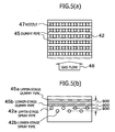
- dummy pipes 45 and 46 which are formed by members having substantially the same construction as that of the header pipes forming the spray header 42, are provided over and under the spray header 42. Between the dummy pipes 45 and 46 and the spray header 42, there is provided a distance of about 1 to 1.5 times of the distance between the upper and lower stages of the header pipes 3 arranged in a zigzag form.
- the dummy pipes 45 and 46 are formed by hollow pipes.
- the dummy pipes 45 and 46 are shown schematically in cross section.
- the dummy pipes 45 and 46 are also arranged in a zigzag form like the header pipes forming the spray header 42.
- Figures 5(a) and 5(b) show the positional relationship between the upper dummy pipes 45 and the spray header 42.
- Figure 5(a) is a view in which the interior of the absorption tower 41 is viewed from the tower top. In this figure, the lower dummy pipes 46 are excluded. As shown in Figure 5(a), between the dummy pipes 45, nozzles 47 of the spray header 42 are located. An arrow mark 48 shows the flow direction of gas from an untreated gas introduction port 43.
- Figure 5(b) shows the interior of the absorption tower 41 viewed from the untreated gas introduction port 43 side.
- Upper-stage dummy pipes 45a and lower-stage dummy pipes 45b on the upper side are arranged in a zigzag form.
- upper- and lower-stage header pipes 42a and 42b are also arranged in a zigzag form.
- untreated exhaust gas 48 is introduced from the side surface side between the upper-stage dummy pipes 45a and the lower-stage dummy pipes 45b.
- Figures 6(a) and 6(b) show the positional relationship between the lower dummy pipes 46 and the spray header 42.
- Figure 6(a) is a view in which the interior of the absorption tower 41 is viewed from the tower top. In this figure, the upper dummy pipes 45 are excluded. As shown in Figure 6(a), between the dummy pipes 46, the nozzles 47 of the spray header 42 are located. The arrow mark 48 shows the flow direction of gas from the untreated gas introduction port 43.
- Figure 6(b) shows the interior of the absorption tower 41 viewed from the untreated gas introduction port 43 side.
- Upper-stage dummy pipes 46a and lower-stage dummy pipes 46b on the lower side are arranged in a zigzag form.
- the upper- and lower-stage header pipes 42a and 42b are also arranged in a zigzag form.
- the untreated exhaust gas 48 is introduced from the side surface side between the upper-stage dummy pipes 46a and the lower-stage dummy pipes 46b.
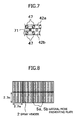
- a region 71 having a falling liquid amount larger than that of other regions is produced on the diagonal lines of a unit lattice formed by the centers of a total of four nozzles 47 consisting of the two nozzles 47 adjoining above the header pipe 42a and the two nozzles 47 adjoining above the adjacent header pipe 42b. Therefore, as explained with reference to Figures 5 and 6, in this embodiment, the dummy pipes 45 and 46 are provided so as to lap on this region 71.
- exhaust gas is discharged as treated gas 51 having been subjected to wet desulfurization after mist is removed by a mist eliminator 50.
- the absorbing solution from the storage tank 44 circulates and is sent to the spray header 42.
- Figure 4 shows only the configuration of the outline of the absorption tower 41, the additional provision of ordinary peripheral equipment and control equipment, which are usually used by the person skilled in the art, is also embraced in the technical scope of the present invention.
- dummy pipes 45 and 46 are provided over and under the spray header 42 in this embodiment, these pipes can be provided only either over or under the spray header 42. Further, although the dummy pipes are used in this embodiment, any columnar liquid drop dispersing member that achieves an equivalent effect can be used in the present invention.
- drift preventing plates 5a and 5b of the embodiment shown in Figure 1 Four types of tests with the following specifications were conducted by using the drift preventing plates 5a and 5b of the embodiment shown in Figure 1.
- an exhaust simulated gas was introduced from a lower part of the absorption tower 1, desulfurization was accomplished by using limestone slurry, and SO 2 was measured at the outlet in tower top portion to evaluate the performance.
- one section of the drift preventing plates 5a and 5b was made a square of 2.7 m as viewed from the tower top.
- Example Example 1 Example 2
- Example 3 Example 4 In-tower temperature [°C] 50 50 50 50 50 Gas flow velocity [m/s] 4 4 4 4 Inlet SO 2 concentration [ppm] 500 500 500 500 Limestone concentration [mmol/l] 30 30 30 30 Liquid column tower nozzle spray height [m] 6 6 6 6 Liquid top portion drift preventing plate installation height [m] 0 1.5 0 1.5 Header portion drift preventing plate installation height [m] 0 0 2 2
- Spray circulation flow rate [m 3 /m 2 /h] 200 200 200
- the pipe diameter was 318 mm in all examples.
- Example Example 5 Example 6
- Example 7 Example 8 In-tower temperature [°C] 50 50 50 50
- Liquid column tower nozzle spray height [m] 6 6 6 6 Dummy pipes over header Absent Present Absent Present Dummy pipes under header Absent Absent Present Spray circulation flow rate [m 3 /m 2 /h] 200 200 200 200
- Outlet SO 2 concentration [ppm] 55 45 33 25 SO 2 removal efficiency [%] 89 91 93 95
Landscapes
- Engineering & Computer Science (AREA)
- Chemical & Material Sciences (AREA)
- Environmental & Geological Engineering (AREA)
- Life Sciences & Earth Sciences (AREA)
- General Engineering & Computer Science (AREA)
- Chemical Kinetics & Catalysis (AREA)
- Oil, Petroleum & Natural Gas (AREA)
- General Chemical & Material Sciences (AREA)
- Analytical Chemistry (AREA)
- Civil Engineering (AREA)
- Structural Engineering (AREA)
- Environmental Sciences (AREA)
- Health & Medical Sciences (AREA)
- Paleontology (AREA)
- Mining & Mineral Resources (AREA)
- General Life Sciences & Earth Sciences (AREA)
- Biomedical Technology (AREA)
- Marine Sciences & Fisheries (AREA)
- Animal Husbandry (AREA)
- Biodiversity & Conservation Biology (AREA)
- Zoology (AREA)
- Ocean & Marine Engineering (AREA)
- Mechanical Engineering (AREA)
- Treating Waste Gases (AREA)
- Gas Separation By Absorption (AREA)
Priority Applications (2)
| Application Number | Priority Date | Filing Date | Title |
|---|---|---|---|
| EP13199592.0A EP2716346A3 (de) | 2004-11-01 | 2005-10-24 | Abgasbehandlungsvorrichtung |
| EP13199590.4A EP2716345A3 (de) | 2004-11-01 | 2005-10-24 | Abgasbehandlungsvorrichtung |
Applications Claiming Priority (1)
| Application Number | Priority Date | Filing Date | Title |
|---|---|---|---|
| JP2004317663A JP2006122862A (ja) | 2004-11-01 | 2004-11-01 | 排ガス処理装置 |
Related Child Applications (2)
| Application Number | Title | Priority Date | Filing Date |
|---|---|---|---|
| EP13199590.4A Division EP2716345A3 (de) | 2004-11-01 | 2005-10-24 | Abgasbehandlungsvorrichtung |
| EP13199592.0A Division EP2716346A3 (de) | 2004-11-01 | 2005-10-24 | Abgasbehandlungsvorrichtung |
Publications (2)
| Publication Number | Publication Date |
|---|---|
| EP1661615A2 true EP1661615A2 (de) | 2006-05-31 |
| EP1661615A3 EP1661615A3 (de) | 2006-09-27 |
Family
ID=36051542
Family Applications (3)
| Application Number | Title | Priority Date | Filing Date |
|---|---|---|---|
| EP13199590.4A Withdrawn EP2716345A3 (de) | 2004-11-01 | 2005-10-24 | Abgasbehandlungsvorrichtung |
| EP05292234A Withdrawn EP1661615A3 (de) | 2004-11-01 | 2005-10-24 | Abgasbehandlungsvorrichtung |
| EP13199592.0A Withdrawn EP2716346A3 (de) | 2004-11-01 | 2005-10-24 | Abgasbehandlungsvorrichtung |
Family Applications Before (1)
| Application Number | Title | Priority Date | Filing Date |
|---|---|---|---|
| EP13199590.4A Withdrawn EP2716345A3 (de) | 2004-11-01 | 2005-10-24 | Abgasbehandlungsvorrichtung |
Family Applications After (1)
| Application Number | Title | Priority Date | Filing Date |
|---|---|---|---|
| EP13199592.0A Withdrawn EP2716346A3 (de) | 2004-11-01 | 2005-10-24 | Abgasbehandlungsvorrichtung |
Country Status (6)
| Country | Link |
|---|---|
| US (1) | US7462330B2 (de) |
| EP (3) | EP2716345A3 (de) |
| JP (1) | JP2006122862A (de) |
| KR (1) | KR100652856B1 (de) |
| CN (1) | CN100464823C (de) |
| TW (1) | TWI280151B (de) |
Cited By (1)
| Publication number | Priority date | Publication date | Assignee | Title |
|---|---|---|---|---|
| CN101664621B (zh) * | 2008-09-02 | 2011-11-16 | 徐志远 | 烟气除尘净化装置 |
Families Citing this family (8)
| Publication number | Priority date | Publication date | Assignee | Title |
|---|---|---|---|---|
| JP2006122862A (ja) * | 2004-11-01 | 2006-05-18 | Mitsubishi Heavy Ind Ltd | 排ガス処理装置 |
| CN103768923B (zh) * | 2014-02-12 | 2015-01-28 | 南京大学环境规划设计研究院有限公司 | 一种中低浓度二甲胺废气多级梯度吸收装置及其吸收方法 |
| CN105749734B (zh) * | 2016-04-29 | 2018-06-22 | 中电投远达环保工程有限公司重庆科技分公司 | 自适应沸腾式泡沫脱硫除尘装置 |
| KR102620035B1 (ko) * | 2019-03-29 | 2023-12-29 | 미츠비시 파워 가부시키가이샤 | 배연 탈황 장치 |
| CN110411268A (zh) * | 2019-08-27 | 2019-11-05 | 中国华能集团清洁能源技术研究院有限公司 | 一种规整填料与散装填料分段布置的填料塔、烟气处理方法 |
| CN110425924A (zh) * | 2019-08-27 | 2019-11-08 | 中国华能集团清洁能源技术研究院有限公司 | 一种烟气余热回收的分阶段换热喷淋填料塔、烟气处理方法 |
| KR102754860B1 (ko) * | 2022-04-27 | 2025-01-15 | (주)로우카본 | 제철소용 이산화탄소 포집 및 탄소자원화, 및 수소 생산 시스템 |
| KR102757058B1 (ko) * | 2022-04-27 | 2025-01-22 | (주)로우카본 | 석탄가스화 복합발전용 이산화탄소 및 황산화물 포집, 및 탄소자원화 시스템 |
Citations (1)
| Publication number | Priority date | Publication date | Assignee | Title |
|---|---|---|---|---|
| JPS5953828A (ja) | 1982-09-21 | 1984-03-28 | Konishiroku Photo Ind Co Ltd | 画像記録複写装置 |
Family Cites Families (19)
| Publication number | Priority date | Publication date | Assignee | Title |
|---|---|---|---|---|
| US2180586A (en) * | 1937-12-01 | 1939-11-21 | Binks Mfg Co | Spray booth |
| US3683593A (en) | 1970-04-23 | 1972-08-15 | Nat Dust Collector Corp | Gas scrubber having tiltable grids and method of using |
| JP3124081B2 (ja) * | 1991-11-13 | 2001-01-15 | 三菱重工業株式会社 | 充填塔スプレーの分散方法 |
| TW259725B (de) | 1994-04-11 | 1995-10-11 | Mitsubishi Heavy Ind Ltd | |
| JP3132957B2 (ja) | 1994-04-11 | 2001-02-05 | 三菱重工業株式会社 | セラミックス製ノズルの支持構造 |
| JP3025147B2 (ja) | 1994-05-17 | 2000-03-27 | 三菱重工業株式会社 | 湿式排煙脱硫装置 |
| JP3207433B2 (ja) | 1996-02-01 | 2001-09-10 | 三菱重工業株式会社 | 排煙脱硫装置 |
| JP3068452B2 (ja) | 1996-02-06 | 2000-07-24 | 三菱重工業株式会社 | 湿式排煙脱硫装置 |
| JPH09225256A (ja) | 1996-02-21 | 1997-09-02 | Mitsubishi Heavy Ind Ltd | 排煙脱硫装置 |
| US5840263A (en) * | 1996-05-30 | 1998-11-24 | Mitsubishi Heavy Industries, Ltd. | Flue gas treating process and system |
| DE19640075C1 (de) * | 1996-09-28 | 1997-08-21 | Lentjes Bischoff Gmbh | Waschturm für Rauchgasentschwefelungsanlagen |
| JPH10156129A (ja) | 1996-11-28 | 1998-06-16 | Babcock Hitachi Kk | 吸収塔 |
| JPH10323528A (ja) * | 1997-05-23 | 1998-12-08 | Mitsubishi Heavy Ind Ltd | 気液接触装置 |
| JPH1147538A (ja) | 1997-08-01 | 1999-02-23 | Babcock Hitachi Kk | 吸収塔 |
| EP0951336B1 (de) | 1997-11-11 | 2005-04-27 | Mitsubishi Heavy Industries, Ltd. | Verfahren und vorrichtung zur nassreinigung eines gases |
| US20050046052A1 (en) * | 2003-07-11 | 2005-03-03 | Kenichi Okada | Exhaust gas treating tower |
| CN1235666C (zh) | 2003-07-19 | 2006-01-11 | 重庆正和生物能源有限公司 | 烟气脱硫脱氮除尘工艺及装置 |
| CN2635194Y (zh) | 2003-08-26 | 2004-08-25 | 天津市东方暖通设备股份合作公司 | 废碱液脱硫反应塔 |
| JP2006122862A (ja) * | 2004-11-01 | 2006-05-18 | Mitsubishi Heavy Ind Ltd | 排ガス処理装置 |
-
2004
- 2004-11-01 JP JP2004317663A patent/JP2006122862A/ja not_active Withdrawn
-
2005
- 2005-04-07 TW TW094111027A patent/TWI280151B/zh not_active IP Right Cessation
- 2005-04-21 KR KR1020050032935A patent/KR100652856B1/ko not_active Expired - Fee Related
- 2005-07-05 CN CNB2005100824977A patent/CN100464823C/zh not_active Expired - Fee Related
- 2005-08-16 US US11/204,385 patent/US7462330B2/en active Active
- 2005-10-24 EP EP13199590.4A patent/EP2716345A3/de not_active Withdrawn
- 2005-10-24 EP EP05292234A patent/EP1661615A3/de not_active Withdrawn
- 2005-10-24 EP EP13199592.0A patent/EP2716346A3/de not_active Withdrawn
Patent Citations (1)
| Publication number | Priority date | Publication date | Assignee | Title |
|---|---|---|---|---|
| JPS5953828A (ja) | 1982-09-21 | 1984-03-28 | Konishiroku Photo Ind Co Ltd | 画像記録複写装置 |
Cited By (1)
| Publication number | Priority date | Publication date | Assignee | Title |
|---|---|---|---|---|
| CN101664621B (zh) * | 2008-09-02 | 2011-11-16 | 徐志远 | 烟气除尘净化装置 |
Also Published As
| Publication number | Publication date |
|---|---|
| TWI280151B (en) | 2007-05-01 |
| US20060093534A1 (en) | 2006-05-04 |
| JP2006122862A (ja) | 2006-05-18 |
| EP1661615A3 (de) | 2006-09-27 |
| TW200615037A (en) | 2006-05-16 |
| EP2716345A3 (de) | 2014-08-20 |
| EP2716346A2 (de) | 2014-04-09 |
| EP2716346A3 (de) | 2014-08-20 |
| CN100464823C (zh) | 2009-03-04 |
| CN1768906A (zh) | 2006-05-10 |
| KR100652856B1 (ko) | 2006-12-01 |
| EP2716345A2 (de) | 2014-04-09 |
| KR20060047295A (ko) | 2006-05-18 |
| US7462330B2 (en) | 2008-12-09 |
Similar Documents
| Publication | Publication Date | Title |
|---|---|---|
| KR0179232B1 (ko) | 연도 가스 탈황 습식 세척기용 스프레이 헤더 | |
| JP5744223B2 (ja) | 湿式スクラバおよびプロセスガスを浄化する方法 | |
| DE3783044T2 (de) | Verfahren zur reinigung von gasen und vorrichtung dazu. | |
| US9084961B2 (en) | Gas-liquid contacting plate, gas-liquid contacting laminated block body, gas-liquid contacting laminated structure and gas purification device | |
| CN100371054C (zh) | 具有阶梯托盘的烟道气脱硫系统 | |
| CA2204876A1 (en) | Flue gas scrubbing apparatus | |
| US7462330B2 (en) | Exhaust gas treatment apparatus | |
| CN203816500U (zh) | 一种具有高效除尘性能的脱硫塔 | |
| US5840263A (en) | Flue gas treating process and system | |
| CN202751924U (zh) | 烟气净化塔 | |
| JP2015073990A (ja) | 湿式脱硫スプレー塔用の方法および装置 | |
| WO1999026712A1 (en) | Gas-liquid contactor with liquid redistribution device | |
| CN103623661B (zh) | 一种烟气净化塔 | |
| CN202921125U (zh) | 烟气净化塔 | |
| KR20160083878A (ko) | 기체와 액체 사이의 열 및 질량 교환을 위한 장치 및 방법 | |
| CN108905580B (zh) | 一种配置屋脊式托盘的湿法脱硫塔 | |
| CH640748A5 (de) | Fuellkoerper zum einsatz in einem verfahrenstechnischen apparat und verwendung desselben. | |
| CN202876600U (zh) | 一种用于烟气净化的塔 | |
| JP2003103139A (ja) | 湿式排煙脱硫装置 | |
| JP2004237258A (ja) | 湿式排煙脱硫装置 | |
| US20210146273A1 (en) | Distributor tray for a fractionating column, comprising a compartment for distributing gas | |
| JPH0975659A (ja) | 湿式排煙脱硫装置 | |
| CN206793352U (zh) | 用于烟气脱硫系统的吸收塔 | |
| JPH08126813A (ja) | 湿式排煙脱硫装置の吸収塔 | |
| JPH06198121A (ja) | 吸収塔を備えた湿式排煙脱硫装置 |
Legal Events
| Date | Code | Title | Description |
|---|---|---|---|
| PUAI | Public reference made under article 153(3) epc to a published international application that has entered the european phase |
Free format text: ORIGINAL CODE: 0009012 |
|
| 17P | Request for examination filed |
Effective date: 20051029 |
|
| AK | Designated contracting states |
Kind code of ref document: A2 Designated state(s): AT BE BG CH CY CZ DE DK EE ES FI FR GB GR HU IE IS IT LI LT LU LV MC NL PL PT RO SE SI SK TR |
|
| AX | Request for extension of the european patent |
Extension state: AL BA HR MK YU |
|
| PUAL | Search report despatched |
Free format text: ORIGINAL CODE: 0009013 |
|
| AK | Designated contracting states |
Kind code of ref document: A3 Designated state(s): AT BE BG CH CY CZ DE DK EE ES FI FR GB GR HU IE IS IT LI LT LU LV MC NL PL PT RO SE SI SK TR |
|
| AX | Request for extension of the european patent |
Extension state: AL BA HR MK YU |
|
| AKX | Designation fees paid |
Designated state(s): AT BE BG CH CY CZ DE DK EE ES FI FR GB GR HU IE IS IT LI LT LU LV MC NL PL PT RO SE SI SK TR |
|
| 17Q | First examination report despatched |
Effective date: 20130606 |
|
| RAP1 | Party data changed (applicant data changed or rights of an application transferred) |
Owner name: MITSUBISHI HITACHI POWER SYSTEMS, LTD. |
|
| GRAP | Despatch of communication of intention to grant a patent |
Free format text: ORIGINAL CODE: EPIDOSNIGR1 |
|
| INTG | Intention to grant announced |
Effective date: 20181011 |
|
| STAA | Information on the status of an ep patent application or granted ep patent |
Free format text: STATUS: THE APPLICATION IS DEEMED TO BE WITHDRAWN |
|
| 18D | Application deemed to be withdrawn |
Effective date: 20190222 |