EP1660364B1 - Structure d'une partie avant de vehicule automobile - Google Patents
Structure d'une partie avant de vehicule automobile Download PDFInfo
- Publication number
- EP1660364B1 EP1660364B1 EP04786334A EP04786334A EP1660364B1 EP 1660364 B1 EP1660364 B1 EP 1660364B1 EP 04786334 A EP04786334 A EP 04786334A EP 04786334 A EP04786334 A EP 04786334A EP 1660364 B1 EP1660364 B1 EP 1660364B1
- Authority
- EP
- European Patent Office
- Prior art keywords
- longitudinal
- vehicle
- absorbers
- frame cradle
- energy absorbers
- Prior art date
- Legal status (The legal status is an assumption and is not a legal conclusion. Google has not performed a legal analysis and makes no representation as to the accuracy of the status listed.)
- Not-in-force
Links
Images


Classifications
-
- B—PERFORMING OPERATIONS; TRANSPORTING
- B62—LAND VEHICLES FOR TRAVELLING OTHERWISE THAN ON RAILS
- B62D—MOTOR VEHICLES; TRAILERS
- B62D21/00—Understructures, i.e. chassis frame on which a vehicle body may be mounted
- B62D21/15—Understructures, i.e. chassis frame on which a vehicle body may be mounted having impact absorbing means, e.g. a frame designed to permanently or temporarily change shape or dimension upon impact with another body
- B62D21/152—Front or rear frames
-
- B—PERFORMING OPERATIONS; TRANSPORTING
- B62—LAND VEHICLES FOR TRAVELLING OTHERWISE THAN ON RAILS
- B62D—MOTOR VEHICLES; TRAILERS
- B62D21/00—Understructures, i.e. chassis frame on which a vehicle body may be mounted
- B62D21/15—Understructures, i.e. chassis frame on which a vehicle body may be mounted having impact absorbing means, e.g. a frame designed to permanently or temporarily change shape or dimension upon impact with another body
-
- B—PERFORMING OPERATIONS; TRANSPORTING
- B62—LAND VEHICLES FOR TRAVELLING OTHERWISE THAN ON RAILS
- B62D—MOTOR VEHICLES; TRAILERS
- B62D21/00—Understructures, i.e. chassis frame on which a vehicle body may be mounted
-
- B—PERFORMING OPERATIONS; TRANSPORTING
- B62—LAND VEHICLES FOR TRAVELLING OTHERWISE THAN ON RAILS
- B62D—MOTOR VEHICLES; TRAILERS
- B62D21/00—Understructures, i.e. chassis frame on which a vehicle body may be mounted
- B62D21/02—Understructures, i.e. chassis frame on which a vehicle body may be mounted comprising longitudinally or transversely arranged frame members
Definitions
- the present invention relates to the structure of a front part of a motor vehicle.
- the document EP 1256519A discloses a structure of a front part of a motor car according to the preamble of claim 1.
- the present invention relates more particularly to structures of the type comprising, on the one hand, an upper part formed of at least two longitudinal members which extend longitudinally in front of the passenger compartment of the vehicle and which are connected in their front end by a cross member which, in the event of a frontal impact, absorbs a sufficient quantity of energy to minimize the deformation of the side members, and furthermore comprises a lower part formed of at least one frame cradle which supports the functional elements of the vehicle , which consists of at least two longitudinal arms extending towards the front of the vehicle, and which is connected to the side members of the upper part by means of vertical tie rods.
- This type of structure makes it possible to independently treat at least two distinct mechanical characteristics, namely the suspension and the treatment of frontal shocks.
- the lower part of the structure known to those skilled in the art under the name “low path” carries functional elements of the vehicle, for example the powertrain, via a cradle.
- This low path makes it possible to attenuate the vibrations originating from the rolling of the vehicle on the roadway and coming from the engine supported, thanks to the fact that the cradle is partly “decoupled” from the body.
- the upper part of the structure known to those skilled in the art under the name of "high road”, allows to absorb frontal shocks through the resilience of the side members. This high way must therefore absorb the energy resulting from significant shock efforts, so that such a shock does not cause intrusion into the habitable.
- EP-B1-0926048 describes and represents an auxiliary frame located under the side members, the energy absorbed by the transverse absorption elements, located in front of the side members and the auxiliary frame, then being distributed between the side members and the auxiliary frame. As described in the description of this document, this distribution applies in the case of small shocks, for example "pedestrian shocks" in which pedestrians are struck by the vehicle at the bumper, because the The structure shown would cause too much deformation of the auxiliary frame in case of large frontal impacts, for example shocks between two vehicles.
- a front structure must actually handle two different types of shock, small shocks, such as the "pedestrian shock” mentioned above, which generates little energy to absorb by the vehicle and shocks high energy.
- These high energy shocks can be of the “Danner shock” type, ie low speed shocks which should only have the effect of the limited change of parts of the structure, or of the "crash” type, which does not must not cause deformation of the passenger compartment for optimum passenger safety.
- the invention proposes a motor vehicle front part structure of the type described above, characterized in that the two longitudinal arms are connected at their front end by a transverse arm, and in that each absorber has a front end. free.
- the structure comprises energy absorbers whose main longitudinal axis is located in the median vertical plane of each longitudinal arm of the frame cradle.
- the energy absorbers are located substantially at the same height as the longitudinal arms of the frame cradle, so that the forces not received by the absorbers are transmitted, in a longitudinal extension, to the arms of the cradle. According to an alternative embodiment, the energy absorbers are located at a height lower than that longitudinal arms of the frame cradle.
- the value of the longitudinal dimension of the energy absorbers is such that, before the shock, the front end of the energy absorbers is longitudinally recessed from the front end of the cross member of the top part.
- the invention also takes into account the management of small shocks, of the "pedestrian impact" type.
- a crossbar is located in front of the energy absorbers, at the bottom.
- This crossbar is fixed to the frame cradle via substantially longitudinal amounts, which are two lateral uprights whose main axis is located in the median vertical plane of each longitudinal arm of the frame cradle and at least one central upright.
- the energy absorbers overlap the lateral uprights.
- a vehicle front part structure 1 mainly comprises an upper part 10 formed in a substantially horizontal plane, from the passenger compartment towards the front of the vehicle, by longitudinal members 11 which are extended forward by housings 12 and which are connected transversely by a cross member 13 which is fixed on the front end of these housings 12.
- the structure 1 also comprises a lower portion 20 in a substantially horizontal plane and at a height less than that of the upper portion 10.
- This part comprises a frame cradle 21 whose role is to support the functional elements of the vehicle, and more particularly the powertrain.
- This frame cradle 21 is formed, from the passenger compartment towards the front of the vehicle, by at least two longitudinal arms 22 connected at their front end by a transverse arm 23.
- energy absorbers 25 are fixed on the frame cradle 21 in front of the longitudinal arms 22.
- the lower part 20 is connected to the upper part 10 by vertical uprights 30, which are situated near the front end of the lower and upper parts 10.
- the uprights 30 allow the frame cradle 21 to be held and thus create a effort behind the absorbers 25.
- the absorbers 25 have a frustoconical shape whose main axis is longitudinal, whose small diameter base 26 is located longitudinally in front of the large diameter base 27, which is fixed on the frame cradle 21
- the absorbers may have other shapes (for example, a cylindrical shape) without departing from the context of the invention, since the largest dimension of the absorber is substantially longitudinal.
- the large diameter base 27 of the frustoconical absorbers 25 is fixed to the frame cradle 21 and their front end extends towards the front of the vehicle, so that in the initial position before a shock represented figure 2 , the free end before the absorbers 25 is located longitudinally recessed from the cross member 13 of the upper part 10 relative to the front of the vehicle.
- the cross member 13 of the upper portion 10 has geometric characteristics and a prestressing such that the cross member 13 is capable of absorbing big party shock energy.
- one objective is to prevent the impact plane Pi from moving back beyond, from the front end of the side members 11 at the top 10 and from that of the cradle frame 21 in the lower part 20.
- the energy developed by these different shocks is absorbed after a predetermined setback of the impact plane jointly by the absorbers 25 in the lower part 20 and the cross member 13 and the housings 12 in the upper part 10.
- the figures 2 , 2b and 2c represent an example of shock in which the absorbers 25 of the lower part 20 provide part of the energy absorption.
- the figure 2 represents a rest situation in which the front end of the cross member 13 is spaced from the passenger compartment with a value L.
- the front end of the absorbers 25 is distant from the passenger compartment of a value 1 which is less than the value L corresponding to the crossbar 13.
- the impact plane Pi is a vertical plane passing through the end of the cross member 13, which is distant from a vertical plane of the passenger compartment of a value L.
- the figure 2b represents a first phase of the shock.
- This shock is large enough to cause a deformation of the housings 12 and the crossbar 13 and move the impact plane Pi to the passenger compartment.
- the impact plane Pi then comprises the front end of the absorbers 25. If the shock is large enough for the energy to be absorbed, this absorption is then Figure 2c ) by the housings 12 and the cross member 13 in the upper part 10, and secondly by the absorbers 25 in the lower part 20.
- the impact plane Pi does not reach the front end of the absorbers 25 which are intact at the end of the shock, and only the cross member 13 and possibly the housings 12 need to be changed.
- the impact plane Pi reaches the front end of the absorbers 25, continues to back towards the passenger compartment by deforming the absorbers 25, but it does not reach the front end of the frame cradle 21 or the longitudinal members 11.
- the absorbers 25 have provided a portion of the energy absorption and have prevented the plane of impact Pi back to the cabin to the longitudinal members 11 or up to The frame 13, the housings 12 and the absorbers 25 must then be replaced, but the longitudinal members 11 and the cradle 21 are intact.
- the impact plane Pi has moved back towards the passenger compartment and has exceeded the front end of the longitudinal members 12.
- the entire front structure 1 is deformed and must be changed but the uptake of joint energy in the high way through the crossbar 13, the housings 12 and the longitudinal members 11, and in the lower track by the absorbers 25 and the frame cradle 21, allowed there to be no intrusion into the passenger compartment and to ensure the safety of the passengers.
- the absorbers 25 are arranged transversely so that their axis corresponding to their longitudinal main dimension is located in the same vertical plane as the longitudinal axis of the longitudinal members Il.
- This particular arrangement makes it possible, when the shock imposes a compression of the absorbers 25, not to transmit forces to the frame cradle 21 in the lower part 20 in a transverse component.
- This objective of the invention ie not to transmit in a transverse component efforts that would create a spacing of the longitudinal arms, 22, one of the other and a weakening of the frame cradle 21, can be achieved according to two embodiments.
- an absorber 25 is located in the extension of each longitudinal arm 22.
- the forces are integrally transmitted longitudinally from the absorber 25 to the longitudinal arm 22, during a compression of the absorber 25.
- the absorbers 25 are located at a height greater than that of the frame cradle 21.
- the forces are then transmitted from the absorber 25 to the longitudinal arm 22, according to a longitudinal main component and a vertical component.
- the absorbers 25 should be located at the same height as the longitudinal arms 22, but that the absorbers 25 can be located at a height between the longitudinal members 11 and the frame cradle 21.
- absorbers may be located at a height lower than that of the frame cradle 21, if the ground clearance, ie the distance to be respected between the roadway and the lowest part of the vehicle, is sufficient.
- the lower part 20 of the front part structure 1 is compatible with a device for treating pedestrian shocks in a low path.
- This device consists of a transverse bar 41, situated in front of the absorbers 25.
- This bar 41 substantially parallel to the transverse arm 23 of the frame cradle 21, is connected to this frame cradle by means of longitudinal uprights 42.
- the length amounts 42 is such that the transverse bar 41 is located longitudinally in front of the absorbers 25 in minor part 20, and advantageously in front of the front end of the crossbar 13 in the upper part 10.
- the number of the amounts 42 may vary, preferably being at least equal to three.
- the crossbar 41 is carried by at least two lateral uprights 43 and a central upright 44.
- the number of central uprights 44 may vary.
- the lateral uprights 43 extend substantially longitudinally in the extension of the longitudinal arms 22 of the frame cradle 21. This transverse position of the lateral uprights 43 allows an optimal recovery on the longitudinal arms 22 of the forces resulting from a pedestrian impact.
- the lateral uprights 43 and the absorbers 25 are fixed on the frame cradle 21 substantially at the same transverse coast, ie in the axis of the longitudinal arms 22 of the cradle 21.
- Figures 3 and 4 representing a first variant of the second embodiment with the device for treating pedestrian shocks in a low path.
- the absorber 25 may have a recess in its lower part to allow the passage in this housing of the lateral upright 43.
- the housing for the passage of the lateral upright 43 is constituted by a recess in the upper part of the absorber 25.
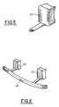
- the figure 5 represents a vehicle structure with a low-pedestrian pedestrian impact device.
- the structure may comprise a single piece 45 formed of an absorber 25 and the associated lateral amount 43.
- This single piece 45 then comprises a first part corresponding to the lateral upright, which is prestressed under a first predetermined force so that this first part can absorb the energy generated by a pedestrian impact, and comprises a second part corresponding to the absorber which is prestressed under a second predetermined force so that this second part can absorb the energy generated by a Danner shock.
- the different prestresses are obtained by different thicknesses and ribbings of the two parts of the single piece 45.
- the transverse bar 41 is preferably fixed to the inner face of the bumpers, ie the side of the shock park facing the vehicle.
- the figure 6 also shown a vehicle structure with a device for treating pedestrian shocks in low lane.
- the structure may comprise a single assembly 46 formed of the transverse bar 41, the lateral uprights 43 and the absorbers 25.
- the assembly 46 heavier than a single absorber 25, must be mounted screwed on the frame cradle 21 so that the weight directed towards the front of the assembly 46 is not too penalizing.
- this single assembly 46 may have a lower fairing 47 extending substantially horizontally below the transverse bar 41 and under the longitudinal struts 42.
- the single assembly 46 is then made such that, when the front part structure 1 is mounted , the lower fairing 47 has continuity with fairings present under the powertrain.
- Such an embodiment with a single assembly 46 provides a front structure whose assembly is easy, and in case of shock, a structure whose replacement is easy.
Applications Claiming Priority (2)
| Application Number | Priority Date | Filing Date | Title |
|---|---|---|---|
| FR0310254A FR2859157B1 (fr) | 2003-08-28 | 2003-08-28 | Structure d'une partie avant de vehicule automobile |
| PCT/FR2004/002169 WO2005023627A1 (fr) | 2003-08-28 | 2004-08-20 | Structure d’une partie avant de vehicule automobile |
Publications (2)
| Publication Number | Publication Date |
|---|---|
| EP1660364A1 EP1660364A1 (fr) | 2006-05-31 |
| EP1660364B1 true EP1660364B1 (fr) | 2009-04-29 |
Family
ID=34130634
Family Applications (1)
| Application Number | Title | Priority Date | Filing Date |
|---|---|---|---|
| EP04786334A Not-in-force EP1660364B1 (fr) | 2003-08-28 | 2004-08-20 | Structure d'une partie avant de vehicule automobile |
Country Status (7)
| Country | Link |
|---|---|
| EP (1) | EP1660364B1 (ko) |
| JP (1) | JP4521403B2 (ko) |
| KR (1) | KR101114035B1 (ko) |
| AT (1) | ATE430080T1 (ko) |
| DE (1) | DE602004020902D1 (ko) |
| FR (1) | FR2859157B1 (ko) |
| WO (1) | WO2005023627A1 (ko) |
Families Citing this family (7)
| Publication number | Priority date | Publication date | Assignee | Title |
|---|---|---|---|---|
| DE102005039469A1 (de) * | 2005-08-20 | 2007-02-22 | Hbpo Gmbh | Frontendmodul mit einem Montageträger mit unterem Querträger |
| FR2893581B1 (fr) * | 2005-11-22 | 2008-02-15 | Renault Sas | Structure deformable de la partie avant d'un vehicule automobile |
| DE102006011145A1 (de) * | 2006-03-10 | 2007-09-20 | GM Global Technology Operations, Inc., Detroit | Karosserievorderbau für ein Kraftfahrzeug |
| FR2952017B1 (fr) * | 2009-11-05 | 2014-10-24 | Peugeot Citroen Automobiles Sa | Partie avant de caisse de vehicule automobile |
| JP5426457B2 (ja) * | 2010-04-07 | 2014-02-26 | 本田技研工業株式会社 | 車両用歩行者保護装置 |
| CN108202684B (zh) * | 2016-12-16 | 2023-09-08 | 宇通客车股份有限公司 | 一种碰撞防护结构及使用该碰撞防护结构的汽车 |
| FR3107689B1 (fr) | 2020-02-27 | 2023-05-26 | Psa Automobiles Sa | Véhicule avec structure montrant une troisième voie d’effort entre le berceau et un brancard avant |
Family Cites Families (7)
| Publication number | Priority date | Publication date | Assignee | Title |
|---|---|---|---|---|
| JP2514565Y2 (ja) * | 1989-12-28 | 1996-10-23 | トヨタ自動車株式会社 | フロントサブフレーム |
| DE4302878C2 (de) * | 1992-02-15 | 2001-05-17 | Volkswagen Ag | Nach dem Stülpprinzip arbeitendes Deformationselement |
| FR2741030B1 (fr) * | 1995-11-15 | 1998-01-16 | Matra Automobile | Structure pour vehicule automobile et procede de reparation d'une telle structure |
| DE19835527B4 (de) * | 1998-08-06 | 2006-10-26 | Suspa Holding Gmbh | Schutzvorrichtung für Kraftfahrzeuge |
| JP4501267B2 (ja) * | 2000-10-13 | 2010-07-14 | マツダ株式会社 | 自動車の前部車体構造 |
| FR2824523B1 (fr) * | 2001-05-11 | 2003-10-10 | Peugeot Citroen Automobiles Sa | Structure de vehicule automobile a compotement ameliore au choc |
| EP1281603B1 (en) * | 2001-07-31 | 2005-11-02 | Nissan Motor Company Limited | Front structure for a vehicle |
-
2003
- 2003-08-28 FR FR0310254A patent/FR2859157B1/fr not_active Expired - Fee Related
-
2004
- 2004-08-20 AT AT04786334T patent/ATE430080T1/de not_active IP Right Cessation
- 2004-08-20 EP EP04786334A patent/EP1660364B1/fr not_active Not-in-force
- 2004-08-20 WO PCT/FR2004/002169 patent/WO2005023627A1/fr active Application Filing
- 2004-08-20 JP JP2006524389A patent/JP4521403B2/ja not_active Expired - Fee Related
- 2004-08-20 DE DE602004020902T patent/DE602004020902D1/de active Active
- 2004-08-20 KR KR1020067003754A patent/KR101114035B1/ko active IP Right Grant
Also Published As
| Publication number | Publication date |
|---|---|
| FR2859157B1 (fr) | 2007-01-26 |
| FR2859157A1 (fr) | 2005-03-04 |
| JP2007504033A (ja) | 2007-03-01 |
| JP4521403B2 (ja) | 2010-08-11 |
| DE602004020902D1 (de) | 2009-06-10 |
| EP1660364A1 (fr) | 2006-05-31 |
| KR101114035B1 (ko) | 2012-02-21 |
| WO2005023627A1 (fr) | 2005-03-17 |
| ATE430080T1 (de) | 2009-05-15 |
| KR20060120617A (ko) | 2006-11-27 |
Similar Documents
| Publication | Publication Date | Title |
|---|---|---|
| EP1942033B1 (fr) | Pièce d'appui pour système d'absorption de chocs destinée à être montée en bout d'un longeron d'un véhicule automobile | |
| EP0802100B1 (fr) | Véhicule ferroviaire à cabinet de conduite comportant une structure absorbeuse d'énergie à déformation progressive | |
| EP1874613B1 (fr) | Plancher arriere de vehicule automobile | |
| EP2930067B1 (fr) | Poutre de pare-chocs de véhicule, ensemble pare-chocs et véhicule associés | |
| EP3494028B1 (fr) | Élément de renfort modulable pour caisse de véhicule automobile pour la protection en cas de choc arrière ou de choc latéral | |
| EP1419936B1 (fr) | Appui bas pour chocs piéton de véhicule automobile et pare-chocs de véhicule automobile muni d'un tel appui bas | |
| FR3105153A1 (fr) | Structure de partie arriere de caisse de vehicule automobile equipee de longerons et longeronnets | |
| EP1388485B1 (fr) | Structure de véhicule automobile à stabilité améliorée en cas de choc sur la voie basse | |
| EP1660364B1 (fr) | Structure d'une partie avant de vehicule automobile | |
| EP1742826B1 (fr) | Structure avant de vehicule automobile | |
| FR2842152A1 (fr) | Armature de pare-chocs avec elements absorbeur de chocs perfectionne | |
| EP1693283B1 (fr) | Structure avant de véhicule automobile | |
| FR3092067A1 (fr) | Berceau moteur pour véhicule automobile et véhicule comportant un tel berceau | |
| FR2990920A1 (fr) | Dispositif de structure destine a etre monte sur un element de chassis de vehicule automobile | |
| FR2810940A1 (fr) | Bloc avant comprenant des elements d'absorption d'energie de choc et vehicule automobile correspondant | |
| EP2210799B1 (fr) | Ensemble de carénage sous moteur pour une structure avant d'un véhicule automobile | |
| EP2207709B1 (fr) | Vehicule automobile comportant une traverse une face avant technique et un convergent fixes les uns sur les autres | |
| EP2185384B1 (fr) | Pare-chocs pour vehicule automobile | |
| WO2005105528A1 (fr) | Boitier de deformation pour vehicule automobile | |
| FR2871122A1 (fr) | Poutre de pare-chocs a moyens de montage d'un organe de remorquage et vehicule automobile correspondant | |
| FR2882327A1 (fr) | Structure avant de vehicule automobile | |
| EP1847445B1 (fr) | Structure avant de véhicule automobile et un procédé correspondant | |
| WO2007135327A1 (fr) | Structure de vehicule automobile comportant un support d'attelage | |
| FR2895351A1 (fr) | Structure avant de vehicule automobile et vehicule correspondant | |
| FR2926052A1 (fr) | Structure avant de vehicule automobile. |
Legal Events
| Date | Code | Title | Description |
|---|---|---|---|
| PUAI | Public reference made under article 153(3) epc to a published international application that has entered the european phase |
Free format text: ORIGINAL CODE: 0009012 |
|
| 17P | Request for examination filed |
Effective date: 20060328 |
|
| AK | Designated contracting states |
Kind code of ref document: A1 Designated state(s): AT BE BG CH CY CZ DE DK EE ES FI FR GB GR HU IE IT LI LU MC NL PL PT RO SE SI SK TR |
|
| 17Q | First examination report despatched |
Effective date: 20060719 |
|
| DAX | Request for extension of the european patent (deleted) | ||
| GRAP | Despatch of communication of intention to grant a patent |
Free format text: ORIGINAL CODE: EPIDOSNIGR1 |
|
| GRAS | Grant fee paid |
Free format text: ORIGINAL CODE: EPIDOSNIGR3 |
|
| GRAA | (expected) grant |
Free format text: ORIGINAL CODE: 0009210 |
|
| AK | Designated contracting states |
Kind code of ref document: B1 Designated state(s): AT BE BG CH CY CZ DE DK EE ES FI FR GB GR HU IE IT LI LU MC NL PL PT RO SE SI SK TR |
|
| REG | Reference to a national code |
Ref country code: GB Ref legal event code: FG4D Free format text: NOT ENGLISH |
|
| REG | Reference to a national code |
Ref country code: CH Ref legal event code: EP |
|
| REF | Corresponds to: |
Ref document number: 602004020902 Country of ref document: DE Date of ref document: 20090610 Kind code of ref document: P |
|
| REG | Reference to a national code |
Ref country code: IE Ref legal event code: FG4D |
|
| NLV1 | Nl: lapsed or annulled due to failure to fulfill the requirements of art. 29p and 29m of the patents act | ||
| PG25 | Lapsed in a contracting state [announced via postgrant information from national office to epo] |
Ref country code: PT Free format text: LAPSE BECAUSE OF FAILURE TO SUBMIT A TRANSLATION OF THE DESCRIPTION OR TO PAY THE FEE WITHIN THE PRESCRIBED TIME-LIMIT Effective date: 20090829 Ref country code: AT Free format text: LAPSE BECAUSE OF FAILURE TO SUBMIT A TRANSLATION OF THE DESCRIPTION OR TO PAY THE FEE WITHIN THE PRESCRIBED TIME-LIMIT Effective date: 20090429 Ref country code: ES Free format text: LAPSE BECAUSE OF FAILURE TO SUBMIT A TRANSLATION OF THE DESCRIPTION OR TO PAY THE FEE WITHIN THE PRESCRIBED TIME-LIMIT Effective date: 20090809 Ref country code: FI Free format text: LAPSE BECAUSE OF FAILURE TO SUBMIT A TRANSLATION OF THE DESCRIPTION OR TO PAY THE FEE WITHIN THE PRESCRIBED TIME-LIMIT Effective date: 20090429 |
|
| PG25 | Lapsed in a contracting state [announced via postgrant information from national office to epo] |
Ref country code: PL Free format text: LAPSE BECAUSE OF FAILURE TO SUBMIT A TRANSLATION OF THE DESCRIPTION OR TO PAY THE FEE WITHIN THE PRESCRIBED TIME-LIMIT Effective date: 20090429 Ref country code: SE Free format text: LAPSE BECAUSE OF FAILURE TO SUBMIT A TRANSLATION OF THE DESCRIPTION OR TO PAY THE FEE WITHIN THE PRESCRIBED TIME-LIMIT Effective date: 20090729 Ref country code: NL Free format text: LAPSE BECAUSE OF FAILURE TO SUBMIT A TRANSLATION OF THE DESCRIPTION OR TO PAY THE FEE WITHIN THE PRESCRIBED TIME-LIMIT Effective date: 20090429 Ref country code: SI Free format text: LAPSE BECAUSE OF FAILURE TO SUBMIT A TRANSLATION OF THE DESCRIPTION OR TO PAY THE FEE WITHIN THE PRESCRIBED TIME-LIMIT Effective date: 20090429 |
|
| REG | Reference to a national code |
Ref country code: IE Ref legal event code: FD4D |
|
| PG25 | Lapsed in a contracting state [announced via postgrant information from national office to epo] |
Ref country code: DK Free format text: LAPSE BECAUSE OF FAILURE TO SUBMIT A TRANSLATION OF THE DESCRIPTION OR TO PAY THE FEE WITHIN THE PRESCRIBED TIME-LIMIT Effective date: 20090429 Ref country code: IE Free format text: LAPSE BECAUSE OF FAILURE TO SUBMIT A TRANSLATION OF THE DESCRIPTION OR TO PAY THE FEE WITHIN THE PRESCRIBED TIME-LIMIT Effective date: 20090429 Ref country code: CZ Free format text: LAPSE BECAUSE OF FAILURE TO SUBMIT A TRANSLATION OF THE DESCRIPTION OR TO PAY THE FEE WITHIN THE PRESCRIBED TIME-LIMIT Effective date: 20090429 Ref country code: EE Free format text: LAPSE BECAUSE OF FAILURE TO SUBMIT A TRANSLATION OF THE DESCRIPTION OR TO PAY THE FEE WITHIN THE PRESCRIBED TIME-LIMIT Effective date: 20090429 Ref country code: RO Free format text: LAPSE BECAUSE OF FAILURE TO SUBMIT A TRANSLATION OF THE DESCRIPTION OR TO PAY THE FEE WITHIN THE PRESCRIBED TIME-LIMIT Effective date: 20090429 |
|
| PG25 | Lapsed in a contracting state [announced via postgrant information from national office to epo] |
Ref country code: SK Free format text: LAPSE BECAUSE OF FAILURE TO SUBMIT A TRANSLATION OF THE DESCRIPTION OR TO PAY THE FEE WITHIN THE PRESCRIBED TIME-LIMIT Effective date: 20090429 |
|
| BERE | Be: lapsed |
Owner name: RENAULT S.A.S. Effective date: 20090831 |
|
| PLBE | No opposition filed within time limit |
Free format text: ORIGINAL CODE: 0009261 |
|
| STAA | Information on the status of an ep patent application or granted ep patent |
Free format text: STATUS: NO OPPOSITION FILED WITHIN TIME LIMIT |
|
| PG25 | Lapsed in a contracting state [announced via postgrant information from national office to epo] |
Ref country code: MC Free format text: LAPSE BECAUSE OF NON-PAYMENT OF DUE FEES Effective date: 20090831 Ref country code: BG Free format text: LAPSE BECAUSE OF FAILURE TO SUBMIT A TRANSLATION OF THE DESCRIPTION OR TO PAY THE FEE WITHIN THE PRESCRIBED TIME-LIMIT Effective date: 20090729 |
|
| REG | Reference to a national code |
Ref country code: CH Ref legal event code: PL |
|
| 26N | No opposition filed |
Effective date: 20100201 |
|
| PG25 | Lapsed in a contracting state [announced via postgrant information from national office to epo] |
Ref country code: CH Free format text: LAPSE BECAUSE OF NON-PAYMENT OF DUE FEES Effective date: 20090831 Ref country code: LI Free format text: LAPSE BECAUSE OF NON-PAYMENT OF DUE FEES Effective date: 20090831 |
|
| PG25 | Lapsed in a contracting state [announced via postgrant information from national office to epo] |
Ref country code: BE Free format text: LAPSE BECAUSE OF NON-PAYMENT OF DUE FEES Effective date: 20090831 |
|
| PG25 | Lapsed in a contracting state [announced via postgrant information from national office to epo] |
Ref country code: GR Free format text: LAPSE BECAUSE OF FAILURE TO SUBMIT A TRANSLATION OF THE DESCRIPTION OR TO PAY THE FEE WITHIN THE PRESCRIBED TIME-LIMIT Effective date: 20090730 |
|
| PG25 | Lapsed in a contracting state [announced via postgrant information from national office to epo] |
Ref country code: IT Free format text: LAPSE BECAUSE OF FAILURE TO SUBMIT A TRANSLATION OF THE DESCRIPTION OR TO PAY THE FEE WITHIN THE PRESCRIBED TIME-LIMIT Effective date: 20090429 |
|
| PG25 | Lapsed in a contracting state [announced via postgrant information from national office to epo] |
Ref country code: LU Free format text: LAPSE BECAUSE OF NON-PAYMENT OF DUE FEES Effective date: 20090820 |
|
| PG25 | Lapsed in a contracting state [announced via postgrant information from national office to epo] |
Ref country code: HU Free format text: LAPSE BECAUSE OF FAILURE TO SUBMIT A TRANSLATION OF THE DESCRIPTION OR TO PAY THE FEE WITHIN THE PRESCRIBED TIME-LIMIT Effective date: 20091030 |
|
| PG25 | Lapsed in a contracting state [announced via postgrant information from national office to epo] |
Ref country code: TR Free format text: LAPSE BECAUSE OF FAILURE TO SUBMIT A TRANSLATION OF THE DESCRIPTION OR TO PAY THE FEE WITHIN THE PRESCRIBED TIME-LIMIT Effective date: 20090429 |
|
| PG25 | Lapsed in a contracting state [announced via postgrant information from national office to epo] |
Ref country code: CY Free format text: LAPSE BECAUSE OF FAILURE TO SUBMIT A TRANSLATION OF THE DESCRIPTION OR TO PAY THE FEE WITHIN THE PRESCRIBED TIME-LIMIT Effective date: 20090429 |
|
| REG | Reference to a national code |
Ref country code: FR Ref legal event code: PLFP Year of fee payment: 12 |
|
| REG | Reference to a national code |
Ref country code: FR Ref legal event code: PLFP Year of fee payment: 13 |
|
| REG | Reference to a national code |
Ref country code: FR Ref legal event code: PLFP Year of fee payment: 14 |
|
| REG | Reference to a national code |
Ref country code: FR Ref legal event code: PLFP Year of fee payment: 15 |
|
| PGFP | Annual fee paid to national office [announced via postgrant information from national office to epo] |
Ref country code: FR Payment date: 20210819 Year of fee payment: 18 |
|
| PGFP | Annual fee paid to national office [announced via postgrant information from national office to epo] |
Ref country code: DE Payment date: 20210819 Year of fee payment: 18 Ref country code: GB Payment date: 20210820 Year of fee payment: 18 |
|
| REG | Reference to a national code |
Ref country code: DE Ref legal event code: R119 Ref document number: 602004020902 Country of ref document: DE |
|
| GBPC | Gb: european patent ceased through non-payment of renewal fee |
Effective date: 20220820 |
|
| PG25 | Lapsed in a contracting state [announced via postgrant information from national office to epo] |
Ref country code: FR Free format text: LAPSE BECAUSE OF NON-PAYMENT OF DUE FEES Effective date: 20220831 Ref country code: DE Free format text: LAPSE BECAUSE OF NON-PAYMENT OF DUE FEES Effective date: 20230301 |
|
| PG25 | Lapsed in a contracting state [announced via postgrant information from national office to epo] |
Ref country code: GB Free format text: LAPSE BECAUSE OF NON-PAYMENT OF DUE FEES Effective date: 20220820 |