EP1660258B1 - A method for forming a cam-engaged rocker arm - Google Patents
A method for forming a cam-engaged rocker arm Download PDFInfo
- Publication number
- EP1660258B1 EP1660258B1 EP04782165A EP04782165A EP1660258B1 EP 1660258 B1 EP1660258 B1 EP 1660258B1 EP 04782165 A EP04782165 A EP 04782165A EP 04782165 A EP04782165 A EP 04782165A EP 1660258 B1 EP1660258 B1 EP 1660258B1
- Authority
- EP
- European Patent Office
- Prior art keywords
- metal
- valve
- blank
- thickness
- article
- Prior art date
- Legal status (The legal status is an assumption and is not a legal conclusion. Google has not performed a legal analysis and makes no representation as to the accuracy of the status listed.)
- Not-in-force
Links
Images


Classifications
-
- B—PERFORMING OPERATIONS; TRANSPORTING
- B21—MECHANICAL METAL-WORKING WITHOUT ESSENTIALLY REMOVING MATERIAL; PUNCHING METAL
- B21K—MAKING FORGED OR PRESSED METAL PRODUCTS, e.g. HORSE-SHOES, RIVETS, BOLTS OR WHEELS
- B21K1/00—Making machine elements
- B21K1/20—Making machine elements valve parts
- B21K1/205—Making machine elements valve parts rocker arms
-
- B—PERFORMING OPERATIONS; TRANSPORTING
- B23—MACHINE TOOLS; METAL-WORKING NOT OTHERWISE PROVIDED FOR
- B23P—METAL-WORKING NOT OTHERWISE PROVIDED FOR; COMBINED OPERATIONS; UNIVERSAL MACHINE TOOLS
- B23P15/00—Making specific metal objects by operations not covered by a single other subclass or a group in this subclass
-
- F—MECHANICAL ENGINEERING; LIGHTING; HEATING; WEAPONS; BLASTING
- F01—MACHINES OR ENGINES IN GENERAL; ENGINE PLANTS IN GENERAL; STEAM ENGINES
- F01L—CYCLICALLY OPERATING VALVES FOR MACHINES OR ENGINES
- F01L1/00—Valve-gear or valve arrangements, e.g. lift-valve gear
- F01L1/12—Transmitting gear between valve drive and valve
- F01L1/18—Rocking arms or levers
- F01L1/185—Overhead end-pivot rocking arms
-
- F—MECHANICAL ENGINEERING; LIGHTING; HEATING; WEAPONS; BLASTING
- F01—MACHINES OR ENGINES IN GENERAL; ENGINE PLANTS IN GENERAL; STEAM ENGINES
- F01L—CYCLICALLY OPERATING VALVES FOR MACHINES OR ENGINES
- F01L2301/00—Using particular materials
-
- F—MECHANICAL ENGINEERING; LIGHTING; HEATING; WEAPONS; BLASTING
- F01—MACHINES OR ENGINES IN GENERAL; ENGINE PLANTS IN GENERAL; STEAM ENGINES
- F01L—CYCLICALLY OPERATING VALVES FOR MACHINES OR ENGINES
- F01L2303/00—Manufacturing of components used in valve arrangements
-
- F—MECHANICAL ENGINEERING; LIGHTING; HEATING; WEAPONS; BLASTING
- F01—MACHINES OR ENGINES IN GENERAL; ENGINE PLANTS IN GENERAL; STEAM ENGINES
- F01L—CYCLICALLY OPERATING VALVES FOR MACHINES OR ENGINES
- F01L2305/00—Valve arrangements comprising rollers
Definitions
- the present invention relates to a method of forming a rocker arm including a valve guide.
- the invention relates to using a stamping die having a pair of cavities to form the valve guides of the rocker arm.
- an overhead cam engine typically utilizes a plurality of cam engaged rocker arms to open valves. These rocker arms pivot at one end, contact the valve at an opposite end, and support a roller between the two ends. The roller engages the cam and the cam rotates to move the roller, thereby causing the rocker arm to pivot at a pivot end, and push the valve.
- Rocker arms can be manufactured by casting metals, blanking and forming, ceramic molding, and other methods. Stamping a metal blank to form a cam-engaged rocker arm including a valve stem guide is common in the art.
- the valve stem guides of the rocker arms are typically formed using a punch and cavity, folding or coining process. During the coining process, an upper die and a lower die punch an area of the metal blank to plastically deform the metal blank. Generally, the area of the metal blank being coined has a thickness greater than the remaining metal blank, thereby providing additional material to use in forming the valve guides.
- Figure 1 illustrates a typical metal blank 8 used in the manufacture of a cam-engaged rocker arm.
- the metal blank 8 illustrated is of uniform thickness and is folded by turning up two opposing edges, and valve guides are formed by plastically deforming material to the desired locations. This plastic deformation typically moves material from nearby areas of the blank to build up a valve guide. In this forming operation, the thickness of the blank area that lost material may be below a desired minimum thickness. A desired minimum thickness for a rocker arm must be maintained for purposes of strength and durability after a surface hardening treatment even if some of the material of the blank is used to form valve guides.
- EP 1 122 408 A discloses a method of manufacturing a valve actuating rocker from a metal blank, including the step of thickening the wall of the blank at the region between the valve guides by compressing peripheral ear portions of the blank so that the material thereof plastically flows toward the region to be thickened and an intermediate article is produced having an outline substantially equal to that of the blank without the ears. The thickened part is thereafter punched in order to form two spaced valve guides.
- a method and system for forming a cam-engaged rocker includes a stamping process where metal is forced into die cavities to build up material in a desired area of a blank to create an intermediate article.
- the intermediate article is further formed by a shaving process where the built-up material and additional material is formed into a pair of valve guides for the rocker arm.
- Figure 1 is a top view of a prior art metal blank used for forming a cam- " engaged rocker arm.
- Figure 2 is a perspective view of a cam engaged rocker arm formed in accordance with an embodiment of the present invention.
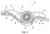
- Figure 3 is a sectional side view of the rocker arm of Figure 1.
- Figure 4 is a top view of a metal blank before forming a cam-engaged rocker arm according to an embodiment of the present invention.
- Figure 5 is a top view of an intermediate article after undergoing a first stamping process according to an embodiment of the present invention.
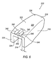
- Figure 6 is a perspective view of a further intermediate article according to an embodiment of the present invention, after undergoing a further stamping operation to form side walls.
- Figure 7 is a front view of the further intermediate article of Figure 6 illustrating the die used for pinch forming valve guides according to an embodiment of the present invention.
- Figure 8 is a front view similar to Figure 7, but illustrating the die after pinch forming the valve guides.
- Figure 9 is a top view of an alternate embodiment of the metal blank of Figure 4.
- a rocker arm 10 is illustrated to include a metal body 12, a valve end 14, a pivot end 16, sidewalls 18, a central portion 20 located between the valve end 14 and the pivot end 16, and a bridge, or cross member, 22 extending between sidewalls 18.
- Metal body 12 is defined by an upper surface 24, a lower surface 26, and an outer peripheral surface 28.
- central portion 20 has a central aperture 30 and roller apertures 32 formed therein.
- Central aperture 30 is defined by an inner surface 34.
- Roller apertures 32 are defined by roller aperture surfaces 36.
- Valve end 14 includes valve guides 40 extending from lower surface 26. Each valve guide 40 is defined, at least in part, by an inboard surface 42, an outboard surface 44, and a distal surface 46.
- a pair of shaved areas, S, are illustrated on lower surface 26, intersecting outboard surfaces 44.
- Valve guides 40 are illustrated to have a height H, measured perpendicular to lower surface 26, between distal surface 46 and lower surface 26.
- inboard surfaces 42 are separated by a distance.
- the pivot end 16 includes a cup 50 formed therein and adapted to rotate on a pivot (not shown).
- metal blank 110 has a valve end 114, a pivot end 116, and a central portion 120 located between the valve end 114 and the pivot end 116.
- the metal blank 110 has an upper surface 124, a lower surface 126, and an outer surface 128.
- Upper surface 124 and lower surface 126, as illustrated, are preferably identical in outline.
- the metal blank 110 has a substantially uniform cross-sectional thickness T as measured between the upper surface 124 and the lower surface 126.
- the metal blank 110 includes an additional material volume, forming ears 140, about the valve end 114.
- the ears 140 include the volume circumscribed by a Line L, the outer surface 128, upper surface 124, and lower surface 126, adjacent valve end 114, and define an outboard portion 160 of the metal blank 110.
- Metal blank 110 is segmented into zones A, B, C, D, E, F, and G, each having a thickness T, as discussed below.
- Figure 5 illustrates an intermediate article 210.
- metal intermediate article 210 has a valve end 214, a pivot end 216, and a central portion 220 located between the valve end 214 and the pivot end 216.
- the intermediate article 210 has an upper surface 224, a lower surface 226, and an outer surface 228.
- the intermediate article 210 has a substantially uniform cross-sectional thickness T as measured between the upper surface 224 and the lower surface 226.
- Intermediate article 210 is shown to include projections 240 defined, at least in part, by an inboard surface 242, an outboard surface 244, and a distal surface 246. As illustrated, inboard surfaces 242 are separated by a distance W.
- Intermediate article 210 is segmented into zones A, B, C, D, E, H, and I.
- Zones A, B, C, D, E, and H each have a thickness T substantially equal to the thickness of metal blank 110.
- Zone I differs from Zone G in that Zone I has projections 240 and Zone G has ears 140.
- the metal blank 110 of Figure 4 can be formed into the intermediate article 210 of Figure 5, as described below.
- Zones A, B, C, D, and E of metal blank 110 and intermediate article 210 are substantially identical.
- Zone G contains ears 140 that are plastically deformed, by a Force P and resulting Force P' ( Figure 4), inward toward each other to produce a resulting Zone I.
- Zones F and H are preferably identical, although Zone H may be slightly distorted with respect to Zone F as a result of the forming operation described herein.
- a further formed intermediate article 310 in the manufacture of rocker arm 10 is illustrated to include a valve end 314, a pivot end 316, and a central portion 320 located between the valve end 314 and the pivot end 316.
- the further formed intermediate article 310 has an upper surface 324, a lower surface 326, and an outer surface 328.
- the further formed intermediate article 310 has a substantially uniform cross-sectional thickness T as measured between the upper surface 324 and the lower surface 326.
- thickness T does not vary between rocker arm 10, metal blank 110, intermediate article 210, and further formed intermediate article 310.
- Further formed intermediate article 310 is shown to include sidewalls 318, a cross member 322, and projections 340 defined, at least in part, by an inboard surface 342, an outboard surface 344, and a distal surface 346.
- inboard surfaces 342 are separated by a Distance X.
- Distance X is substantially equal to Distance W, although a slight variation between these distances caused by the forming operations described herein may be experienced.
- sidewalls 318 are about identical in outline to sidewalls 18.
- stamping die 400 for forming valve guides 40 is illustrated to include a center post 402, a pair of cams 404 having a shaving edge 410.
- Center post 402 is illustrated to include a valve guide forming surface 414.
- Shaving edge 410 is preferably curved to match the curve of the intersecting line between valve guide 40 and lower surface 26, as best seen in Figure 3.
- stamping die 400 has a further formed intermediate article 310 positioned therein and prepared for a shaving operation to create valve guides 40.
- stamping die 400 has one rocker arm 10 positioned therein after the shaving operation has formed valve guides 40.
- the metal blank 110 undergoes a first stamping process in which a stamping die (not shown), having a pair of cavities (not shown) which are used to form the projections 240 of intermediate article 210.
- the cavities of the stamping die are centrally located about the valve end 14 of the metal blank 110.
- the metal blank 110 is stamped such that during the stamping process, the ears 140 from the outboard portion 160 of the metal blank 110 are forced inward toward the cavities of the stamping die, thereby displacing material adjacent lower surface 126 into the cavities to form projections 240 ( Figure 5).
- Projections 240 are formed by drawing the ears 140 from the outboard portion 160 while minimizing any change to the cross-sectional thickness of the intermediate article 210 that does not include projections 240.
- the ears 140 are driven inward, plastically deforming material of metal blank 110 into the pair of cavities of the stamping die, producing projections 240.
- each ear 140 produces a projection 240 during this forming operation.
- intermediate article 210 has an identical outline defined by outer surface 228 as outer surface 128 of metal blank 110 with the exclusion of the ears 140.
- the material volume of ears 140 is about equal to the material volume of the projections 240.
- FIG. 5 best illustrates the intermediate article 210 after the first stamping process has been completed.
- a further processing step of the method presented herein involves the forming of sidewalls 18.
- the intermediate article 210 of Figure 5 is formed into the further formed intermediate article 310 of Figure 6 by a folding operation.
- This folding operation forms sidewalls 318 by folding the sides of further formed intermediate article 310 about 90° toward upper surface 324 along the length of further formed intermediate article 310 from valve end 314 to pivot end 316.
- the further formed intermediate article 310 of Figure 6 undergoes a shaving process to form valve guides 40.
- the shaving process is performed by pinching material between upper surface 324 and lower surface 326 between the cams 404 and shaving the material toward the center post 402.
- the material is plastically deformed toward projections 340, plastically deforming the material of projections 340, until both volumes of material are formed into each valve guide 40.
- This shaving process creates a shaved area S, that is defined by the material of lower surface 26 that was exposed by the shaving process.
- distance X, between projections 340 of further formed intermediate article 310 is greater than the width of center post 402 adjacent lower surface 326.
- inboard surfaces 342 may be angled such that their orientation toward lower surface 326 is less than 90°, and the distance between distal surfaces 346 is greater than the minimum distance between projections 340, thereby eliminating any difficulty of interfering surfaces when positioning further formed intermediate article within die 400.
- the shaving process results in a minimum of approximately 65% of stock thickness being maintained across the shaved area A so as not to create a through harden heat treat condition in the shaved area.
- the stock thickness is the original thickness of metal blank 110 as measured from upper surface 24 to lower surface 26. This stock thickness is preferably about 3 mm (0.12 inch) to about 3.94 mm (0.16 inch). It is desired to maintain a minimum thickness of the resulting rocker arm in the shaved area A, as measured between the shaved area A and the upper surface 24.
- the minimum required thickness for rocker arm 10 adjacent shaved area A is determined by the depth of hardening experienced by rocker arm 10 in a post-forming hardening treatment and the desired soft core thickness. A rocker arm with a hardened surface and soft core is typically desired for purposes of durability and wear resistance. In the embodiment shown, the post forming hardening treatment will harden the rocker arm 10 to a maximum depth of about 0.020 inches measured from all surfaces.
- Figure 9 illustrates a metal blank 510 as an alternate embodiment of the metal blank 110.
- metal blank 510 has a valve end 514, a pivot end 516, and a central portion 520 located between the valve end 514 and the pivot end 516.
- the metal blank 510 has an upper surface 524, a lower surface 526, and an outer surface 528. Upper surface 524 and lower surface 526, as illustrated, are preferably identical in outline.
- the metal blank 510 has a substantially uniform cross-sectional thickness T as measured between the upper surface 524 and the lower surface 526.
- the metal blank 510 includes an additional material volume, forming ears 540, about the valve end 514.
- the ears 540 include the volume circumscribed by a Line M, the outer surface 528, upper surface 524, and lower surface 526, adjacent valve end 514, and define an outboard portion 560 of the metal blank 510.
- Metal blank 510 is segmented into zones A, B, C, D, E, J, and K, each having a thickness T.
- Metal blank 510 is formed into intermediate article 210 by forcing ears 540 into the valve end 514 as metal plastically flows into the cavities forming projections 240, as discussed herein.
- each ear 540 produces a projection 240 on Zone K at valve end 514 during this forming operation.
- Cup 50 and central aperture 30 may be formed in lower surface 26 at any appropriate time when processing metal blank 110 into the rocker arm 10.
- central aperture 30 is formed and cup 50 is formed as the last forming step, after pinch forming of valve guides 40.
- Roller apertures 32 may be formed either by machining or in-die piercing.
- roller apertures 32 are formed after pinch forming valve guides 40.
- Outer curved, or peripheral, surfaces 28, 128, 228, or 528 may be completely curved, have straight portions, or include straight portions intersecting at predetermined angles.
- valve guides are illustrated, another form of the guides may also be useful at the pivot end.
Abstract
Description
- The present invention relates to a method of forming a rocker arm including a valve guide. In particular, the invention relates to using a stamping die having a pair of cavities to form the valve guides of the rocker arm.
- In automotive and other applications, an overhead cam engine typically utilizes a plurality of cam engaged rocker arms to open valves. These rocker arms pivot at one end, contact the valve at an opposite end, and support a roller between the two ends. The roller engages the cam and the cam rotates to move the roller, thereby causing the rocker arm to pivot at a pivot end, and push the valve.
- Rocker arms can be manufactured by casting metals, blanking and forming, ceramic molding, and other methods. Stamping a metal blank to form a cam-engaged rocker arm including a valve stem guide is common in the art. The valve stem guides of the rocker arms are typically formed using a punch and cavity, folding or coining process. During the coining process, an upper die and a lower die punch an area of the metal blank to plastically deform the metal blank. Generally, the area of the metal blank being coined has a thickness greater than the remaining metal blank, thereby providing additional material to use in forming the valve guides. Figure 1 illustrates a typical metal blank 8 used in the manufacture of a cam-engaged rocker arm. The metal blank 8 illustrated is of uniform thickness and is folded by turning up two opposing edges, and valve guides are formed by plastically deforming material to the desired locations. This plastic deformation typically moves material from nearby areas of the blank to build up a valve guide. In this forming operation, the thickness of the blank area that lost material may be below a desired minimum thickness. A desired minimum thickness for a rocker arm must be maintained for purposes of strength and durability after a surface hardening treatment even if some of the material of the blank is used to form valve guides.
- One drawback to this method is the extreme difficulty in providing a blank with sufficient thickness in a desired area for forming the valve guides without making a remaining portion of the rocker arm too thin in a later forming operation. In practice, it has been found to be nearly impossible to balance these competing needs.
-
EP 1 122 408 A discloses a method of manufacturing a valve actuating rocker from a metal blank, including the step of thickening the wall of the blank at the region between the valve guides by compressing peripheral ear portions of the blank so that the material thereof plastically flows toward the region to be thickened and an intermediate article is produced having an outline substantially equal to that of the blank without the ears. The thickened part is thereafter punched in order to form two spaced valve guides. - The present invention overcomes the deficiencies of the prior art by preparing a blank of generally uniform thickness for forming the valve guides of a rocker arm. In one embodiment, a method and system for forming a cam-engaged rocker includes a stamping process where metal is forced into die cavities to build up material in a desired area of a blank to create an intermediate article. The intermediate article is further formed by a shaving process where the built-up material and additional material is formed into a pair of valve guides for the rocker arm.
- Figure 1 is a top view of a prior art metal blank used for forming a cam- " engaged rocker arm.
- Figure 2 is a perspective view of a cam engaged rocker arm formed in accordance with an embodiment of the present invention.
- Figure 3 is a sectional side view of the rocker arm of Figure 1.
- Figure 4 is a top view of a metal blank before forming a cam-engaged rocker arm according to an embodiment of the present invention.
- Figure 5 is a top view of an intermediate article after undergoing a first stamping process according to an embodiment of the present invention.
- Figure 6 is a perspective view of a further intermediate article according to an embodiment of the present invention, after undergoing a further stamping operation to form side walls.
- Figure 7 is a front view of the further intermediate article of Figure 6 illustrating the die used for pinch forming valve guides according to an embodiment of the present invention.
- Figure 8 is a front view similar to Figure 7, but illustrating the die after pinch forming the valve guides.
- Figure 9 is a top view of an alternate embodiment of the metal blank of Figure 4.
- Referring to Figures 2 and 3, a
rocker arm 10 is illustrated to include ametal body 12, avalve end 14, apivot end 16,sidewalls 18, acentral portion 20 located between thevalve end 14 and thepivot end 16, and a bridge, or cross member, 22 extending betweensidewalls 18.Metal body 12 is defined by anupper surface 24, alower surface 26, and an outerperipheral surface 28. As illustrated,central portion 20 has acentral aperture 30 androller apertures 32 formed therein.Central aperture 30 is defined by aninner surface 34.Roller apertures 32 are defined byroller aperture surfaces 36.Valve end 14 includesvalve guides 40 extending fromlower surface 26. Eachvalve guide 40 is defined, at least in part, by aninboard surface 42, anoutboard surface 44, and adistal surface 46. A pair of shaved areas, S, are illustrated onlower surface 26, intersectingoutboard surfaces 44.Valve guides 40 are illustrated to have a height H, measured perpendicular tolower surface 26, betweendistal surface 46 andlower surface 26. As best seen in Figure 3,inboard surfaces 42 are separated by a distance. With continued reference to Figures 2 and 3, thepivot end 16 includes acup 50 formed therein and adapted to rotate on a pivot (not shown). - Referring now to Figure 4, a metal blank 110 is shown according to an embodiment of the present invention. As illustrated, metal blank 110 has a
valve end 114, apivot end 116, and acentral portion 120 located between thevalve end 114 and thepivot end 116. The metal blank 110 has anupper surface 124, alower surface 126, and anouter surface 128.Upper surface 124 andlower surface 126, as illustrated, are preferably identical in outline. The metal blank 110 has a substantially uniform cross-sectional thickness T as measured between theupper surface 124 and thelower surface 126. The metal blank 110 includes an additional material volume, formingears 140, about thevalve end 114. Theears 140 include the volume circumscribed by a Line L, theouter surface 128,upper surface 124, andlower surface 126,adjacent valve end 114, and define anoutboard portion 160 of the metal blank 110. Metal blank 110 is segmented into zones A, B, C, D, E, F, and G, each having a thickness T, as discussed below. - Figure 5 illustrates an
intermediate article 210. As illustrated, metalintermediate article 210 has avalve end 214, apivot end 216, and acentral portion 220 located between thevalve end 214 and thepivot end 216. Theintermediate article 210 has anupper surface 224, alower surface 226, and anouter surface 228. Theintermediate article 210 has a substantially uniform cross-sectional thickness T as measured between theupper surface 224 and thelower surface 226.Intermediate article 210 is shown to includeprojections 240 defined, at least in part, by aninboard surface 242, anoutboard surface 244, and adistal surface 246. As illustrated,inboard surfaces 242 are separated by a distance W.Intermediate article 210 is segmented into zones A, B, C, D, E, H, and I. Zones A, B, C, D, E, and H, each have a thickness T substantially equal to the thickness of metal blank 110. Zone I differs from Zone G in that Zone I hasprojections 240 and Zone G hasears 140.Peripheral surface 228, viewed along the Z-axis, closely approximates the outline of the metal blank 110 withoutears 140, as defined byperipheral surface 128 and Lines L. Thus provided, the metal blank 110 of Figure 4 can be formed into theintermediate article 210 of Figure 5, as described below. As illustrated, Zones A, B, C, D, and E of metal blank 110 andintermediate article 210 are substantially identical. Zone G containsears 140 that are plastically deformed, by a Force P and resulting Force P' (Figure 4), inward toward each other to produce a resulting Zone I. Zones F and H are preferably identical, although Zone H may be slightly distorted with respect to Zone F as a result of the forming operation described herein. - With reference to Figure 6, a further formed
intermediate article 310 in the manufacture ofrocker arm 10 is illustrated to include avalve end 314, apivot end 316, and acentral portion 320 located between thevalve end 314 and thepivot end 316. The further formedintermediate article 310 has anupper surface 324, alower surface 326, and anouter surface 328. The further formedintermediate article 310 has a substantially uniform cross-sectional thickness T as measured between theupper surface 324 and thelower surface 326. Preferably, thickness T does not vary betweenrocker arm 10,metal blank 110,intermediate article 210, and further formedintermediate article 310. Further formedintermediate article 310 is shown to includesidewalls 318, across member 322, andprojections 340 defined, at least in part, by aninboard surface 342, anoutboard surface 344, and adistal surface 346. As illustrated,inboard surfaces 342 are separated by a Distance X. Preferably, Distance X is substantially equal to Distance W, although a slight variation between these distances caused by the forming operations described herein may be experienced. In the embodiment illustrated,sidewalls 318 are about identical in outline to sidewalls 18. - Referring now to Figures 7 and 8, an embodiment of a stamping die 400 for forming valve guides 40 is illustrated to include a
center post 402, a pair ofcams 404 having a shavingedge 410.Center post 402 is illustrated to include a valveguide forming surface 414. Shavingedge 410 is preferably curved to match the curve of the intersecting line betweenvalve guide 40 andlower surface 26, as best seen in Figure 3. As illustrated in Figure 7, stamping die 400 has a further formedintermediate article 310 positioned therein and prepared for a shaving operation to create valve guides 40. As illustrated in Figure 8, stamping die 400 has onerocker arm 10 positioned therein after the shaving operation has formed valve guides 40. - An embodiment of the method of forming the
rocker arm 10 from metal blank 110 will now be described. Themetal blank 110 undergoes a first stamping process in which a stamping die (not shown), having a pair of cavities (not shown) which are used to form theprojections 240 ofintermediate article 210. The cavities of the stamping die are centrally located about thevalve end 14 of themetal blank 110. Themetal blank 110 is stamped such that during the stamping process, theears 140 from theoutboard portion 160 of themetal blank 110 are forced inward toward the cavities of the stamping die, thereby displacing material adjacentlower surface 126 into the cavities to form projections 240 (Figure 5).Projections 240 are formed by drawing theears 140 from theoutboard portion 160 while minimizing any change to the cross-sectional thickness of theintermediate article 210 that does not includeprojections 240. Theears 140 are driven inward, plastically deforming material of metal blank 110 into the pair of cavities of the stamping die, producingprojections 240. Preferably, eachear 140 produces aprojection 240 during this forming operation. Thus formed,intermediate article 210 has an identical outline defined byouter surface 228 asouter surface 128 of metal blank 110 with the exclusion of theears 140. Thus, the material volume ofears 140 is about equal to the material volume of theprojections 240. - At the completion of this stamping step,
projections 240 are positioned within the cavities due to the plastic flow of material frommetal blank 110. Figure 5 best illustrates theintermediate article 210 after the first stamping process has been completed. - A further processing step of the method presented herein involves the forming of
sidewalls 18. In this step, theintermediate article 210 of Figure 5 is formed into the further formedintermediate article 310 of Figure 6 by a folding operation. This folding operation forms sidewalls 318 by folding the sides of further formedintermediate article 310 about 90° towardupper surface 324 along the length of further formedintermediate article 310 fromvalve end 314 to pivotend 316. - As illustrated in Figure 7, the further formed
intermediate article 310 of Figure 6 undergoes a shaving process to form valve guides 40. The shaving process is performed by pinching material betweenupper surface 324 andlower surface 326 between thecams 404 and shaving the material toward thecenter post 402. As the material is shaved, the material is plastically deformed towardprojections 340, plastically deforming the material ofprojections 340, until both volumes of material are formed into eachvalve guide 40. This shaving process creates a shaved area S, that is defined by the material oflower surface 26 that was exposed by the shaving process. As best seen in Figure 7, distance X, betweenprojections 340 of further formedintermediate article 310 is greater than the width ofcenter post 402 adjacentlower surface 326. In this manner, further formedintermediate article 310 can be positioned withindie 400 without having to force further formedintermediate article 310 into position. In an alternate embodiment,inboard surfaces 342 may be angled such that their orientation towardlower surface 326 is less than 90°, and the distance betweendistal surfaces 346 is greater than the minimum distance betweenprojections 340, thereby eliminating any difficulty of interfering surfaces when positioning further formed intermediate article withindie 400. - The shaving process results in a minimum of approximately 65% of stock thickness being maintained across the shaved area A so as not to create a through harden heat treat condition in the shaved area. The stock thickness is the original thickness of metal blank 110 as measured from
upper surface 24 tolower surface 26. This stock thickness is preferably about 3 mm (0.12 inch) to about 3.94 mm (0.16 inch). It is desired to maintain a minimum thickness of the resulting rocker arm in the shaved area A, as measured between the shaved area A and theupper surface 24. The minimum required thickness forrocker arm 10 adjacent shaved area A is determined by the depth of hardening experienced byrocker arm 10 in a post-forming hardening treatment and the desired soft core thickness. A rocker arm with a hardened surface and soft core is typically desired for purposes of durability and wear resistance. In the embodiment shown, the post forming hardening treatment will harden therocker arm 10 to a maximum depth of about 0.020 inches measured from all surfaces. - Figure 9 illustrates a metal blank 510 as an alternate embodiment of the
metal blank 110. As illustrated,metal blank 510 has avalve end 514, apivot end 516, and acentral portion 520 located between thevalve end 514 and thepivot end 516. Themetal blank 510 has anupper surface 524, alower surface 526, and anouter surface 528.Upper surface 524 andlower surface 526, as illustrated, are preferably identical in outline. Themetal blank 510 has a substantially uniform cross-sectional thickness T as measured between theupper surface 524 and thelower surface 526. Themetal blank 510 includes an additional material volume, formingears 540, about thevalve end 514. Theears 540 include the volume circumscribed by a Line M, theouter surface 528,upper surface 524, andlower surface 526,adjacent valve end 514, and define anoutboard portion 560 of themetal blank 510.Metal blank 510 is segmented into zones A, B, C, D, E, J, and K, each having a thickness T. -
Metal blank 510 is formed intointermediate article 210 by forcingears 540 into thevalve end 514 as metal plastically flows into thecavities forming projections 240, as discussed herein. Preferably, eachear 540 produces aprojection 240 on Zone K atvalve end 514 during this forming operation. -
Cup 50 andcentral aperture 30 may be formed inlower surface 26 at any appropriate time when processingmetal blank 110 into therocker arm 10. As presently preferred,central aperture 30 is formed andcup 50 is formed as the last forming step, after pinch forming of valve guides 40.Roller apertures 32 may be formed either by machining or in-die piercing. Preferably,roller apertures 32 are formed after pinch forming valve guides 40. Outer curved, or peripheral, surfaces 28, 128, 228, or 528 may be completely curved, have straight portions, or include straight portions intersecting at predetermined angles. - While the invention has been described with respect to specific examples including preferred modes of carrying out the invention, those skilled in the art will appreciate that there are numerous variations and permutations of the above described systems and techniques that fall within the scope of the invention as set forth in the appended claims. For example, while valve guides are illustrated, another form of the guides may also be useful at the pivot end.
Claims (18)
- A method for manufacturing a cam-engaged rocker comprising:providing an article (310), the article defined, at least in part, by a body defined in part by a first surface (326) and an opposing second surface (324), the first surface having a projection (340) that extends from the body, the article (310) further having a valve end (314) and a pivot end (316), wherein the article contains a predetermined amount of a metal; anddisplacing a portion of the metal between the first surface (326) and the opposing second surface (324) to form a valve guide (40), wherein the valve guide is formed from metal that includes at least a portion of the projection (340), and the valve guide (40) is defined at least by an inboard surface (42) and an outboard surface (44),characterized in that for displacing said portion of the metal, the article (310) is positioned in a die (400) including a center post (402) and a pair of cams (404) each having a shaving edge (410), and the metal is shaved by the cams (404) toward said center post (402).
- The method of Claim 1, further comprising:stamping the article by exerting a force on a metal blank (110) through a stamping die having a cavity, wherein the stamping die is positioned adjacent the article such that the cavity is adjacent the metallic surface at the valve end (114), and the cavity is adapted to permit a portion of the article to increase in thickness, such that the projection (240, 340) is formed by the plastic flow of metal into the cavity, and wherein the force is exerted through an outer curved or peripheral surface.
- The method of Claim 2, wherein stamping the metal blank (110) includes exerting a force in a predetermined direction, and the flow of the metal is generally perpendicular to the predetermined direction.
- The method of Claim 1, 2 or 3, further comprising pinch forming the projection (340) to create at least one valve guide (40).
- The method of claim 4, wherein pinch forming includes a force in a predetermined direction, and pinch forming results in an additional material thickness, wherein the additional material thickness is measured generally perpendicular to the predetermined direction.
- The method of Claim 4, wherein pinch forming includes shaving material between the two opposing surfaces (124, 126), wherein the shaved material is directed to form at least a portion of the valve guide (40), and a shaved area (A) is created.
- The method of Claim 6, wherein a thickness of the rocker arm (10), as measured between the shaved area (A) and an opposing surface (24), is greater than a minimum required thickness.
- The method of Claim 6, wherein pinch forming further includes directing the projection (340) to form at least a portion of the valve guide (40).
- The method of Claim 4, wherein pinch forming further includes pinching a predetermined amount of material between said cam (404) and said center post (402).
- The method of manufacturing a cam-engaged rocker according to Claim 1, comprising:obtaining a metal blank (110), the blank defined, at least in part, by two opposing surfaces (124, 126) and an outer peripheral surface (128), the blank having a generally uniform thickness (T) as measured between the two opposing surfaces (124, 126), wherein the two opposing surfaces each generally lie within a defined plane, the blank (110) further having a valve end (114), a pivot end (116), and at least one ear (140) adjacent the valve end, wherein the ear defines a predetermined portion of the metal blank (110) extending between the two opposing surfaces (124, 126), and the outer peripheral surface (128) defines, in part, an outline of the ear (140); andstamping the metal blank (110) using a stamping die having a pair of cavities to produce the article (210), wherein the stamping die is positioned adjacent the metal blank (110) such that the cavities are adjacent one of the two opposing surfaces (124, 126) at the valve end (114), and the cavities selectively permit portions of the valve end (114) of the blank (110) to increase in thickness as the blank is stamped, such that the at least one ear (140) is pressed inward into the valve end (114) and a pair of projections (240) are formed by the flow of a portion of the metal into the cavities while retaining the cross-sectional thickness (T) between the two opposing surfaces (124, 126), wherein the volume of the pair of projections (240) is substantially equal to the volume of the at least one ear (140), and an outline of the intermediate article (210) is substantially equal to the outline of the metal blank (110) without the ear (140).
- The method of Claim 10, wherein stamping the metal blank (110) includes exerting a force in a predetermined direction, and the plastic flow of the portion of the metal is generally perpendicular to the predetermined direction.
- The method of Claim 10, further comprising pinch forming the projections (240) to create two valve guides (40).
- The method of Claim 12, wherein pinch forming includes exerting a force in a predetermined direction, and pinch forming results in an additional flow of a portion of the metal to form each valve guide (40) with a predetermined height (H), the flow being plastic flow, and wherein the predetermined height (H) is measured generally perpendicular to the predetermined direction.
- The method of Claim 12, wherein pinch forming includes shaving material located between the two opposing surfaces (24, 26), wherein the shaved material is directed to form at least a portion of each valve guide (40), and a shaved area (A) is created.
- The method of Claim 14, wherein a thickness of the rocker arm, as measured between the shaved area (A) and an opposing surface (24), is greater than a minimum required thickness.
- The method of Claim 14, wherein pinch forming further includes directing the projections (240) to form at least a portion of each valve guide (40).
- The method of Claim 12, wherein pinch forming further includes pinching a predetermined amount of material between said pair of cams (404) and the center post (402).
- The method of any one of claims 10 to 17, wherein there are pair of valve guides (40), and there is a separate ear (140; 540) for each valve guide.
Applications Claiming Priority (2)
| Application Number | Priority Date | Filing Date | Title |
|---|---|---|---|
| US49807603P | 2003-08-27 | 2003-08-27 | |
| PCT/US2004/027611 WO2005021183A1 (en) | 2003-08-27 | 2004-08-26 | A method and system for forming a cam-engaged rocker arm |
Publications (2)
| Publication Number | Publication Date |
|---|---|
| EP1660258A1 EP1660258A1 (en) | 2006-05-31 |
| EP1660258B1 true EP1660258B1 (en) | 2007-09-19 |
Family
ID=34272635
Family Applications (1)
| Application Number | Title | Priority Date | Filing Date |
|---|---|---|---|
| EP04782165A Not-in-force EP1660258B1 (en) | 2003-08-27 | 2004-08-26 | A method for forming a cam-engaged rocker arm |
Country Status (6)
| Country | Link |
|---|---|
| US (1) | US20050087162A1 (en) |
| EP (1) | EP1660258B1 (en) |
| JP (1) | JP2007503317A (en) |
| AT (1) | ATE373535T1 (en) |
| DE (1) | DE602004009087T2 (en) |
| WO (1) | WO2005021183A1 (en) |
Families Citing this family (10)
| Publication number | Priority date | Publication date | Assignee | Title |
|---|---|---|---|---|
| US7124957B2 (en) | 2004-11-24 | 2006-10-24 | Optoelectronics Co., Ltd. | Apparatus for reading a color symbol |
| JP4539381B2 (en) * | 2005-03-10 | 2010-09-08 | 日本精工株式会社 | Sheet metal rocker arm manufacturing method |
| JP4685548B2 (en) | 2005-08-22 | 2011-05-18 | 中西金属工業株式会社 | Method for manufacturing rocker arm |
| JP4235196B2 (en) * | 2005-08-22 | 2009-03-11 | 中西金属工業株式会社 | Method for manufacturing rocker arm |
| JP2007205288A (en) | 2006-02-02 | 2007-08-16 | Otics Corp | Rocker arm and its manufacturing method |
| DE102006052821A1 (en) * | 2006-11-09 | 2008-05-15 | Schaeffler Kg | Drag lever for actuating a gas exchange valve of an internal combustion engine |
| JP4858592B2 (en) * | 2009-10-15 | 2012-01-18 | 日本精工株式会社 | Sheet metal rocker arm manufacturing method |
| JP6769691B2 (en) * | 2014-12-26 | 2020-10-14 | 株式会社オティックス | Rocker arm manufacturing method |
| CN107971708B (en) * | 2017-12-04 | 2019-09-13 | 富奥辽宁汽车弹簧有限公司 | A kind of production method of leading arm |
| CN112518260A (en) * | 2020-12-28 | 2021-03-19 | 湖南易通星桥汽车零部件有限公司 | Production process of single guide arm |
Family Cites Families (11)
| Publication number | Priority date | Publication date | Assignee | Title |
|---|---|---|---|---|
| DE69104016T3 (en) * | 1990-11-19 | 1999-09-02 | Nippon Piston Ring Co Ltd | Machine element with at least one connecting part fastened with pressure on a shaft. |
| US5604044A (en) * | 1992-12-28 | 1997-02-18 | Mccabe; Charles J. | Blanks for sheet material forming process |
| JP3497374B2 (en) * | 1998-03-25 | 2004-02-16 | 中西金属工業株式会社 | Rocker arm and method of manufacturing the same |
| JP4186203B2 (en) * | 1999-05-31 | 2008-11-26 | 株式会社ジェイテクト | ROCKER ARM AND ROCKER ARM BODY MANUFACTURING METHOD |
| KR20010078743A (en) * | 1999-08-18 | 2001-08-21 | 타카미츄 무토 | Method of producing rocker arm and rocker arm body |
| JP3785294B2 (en) * | 1999-11-02 | 2006-06-14 | 中西金属工業株式会社 | Rocker arm and manufacturing method thereof |
| US6615635B2 (en) * | 2000-06-20 | 2003-09-09 | Ina Walzlager Schaeffler Ohg | Method of making a lever-type cam follower, and lever-type cam follower |
| DE10030341C2 (en) * | 2000-06-20 | 2003-04-10 | Ina Schaeffler Kg | Process for producing a lever-like cam follower |
| EP1357257B1 (en) * | 2002-04-22 | 2010-05-05 | Schaeffler KG | Rocker arm made of sheet metal |
| JP2004025240A (en) * | 2002-06-26 | 2004-01-29 | Koyo Seiko Co Ltd | Rocker arm and its production method |
| JP3934491B2 (en) * | 2002-06-26 | 2007-06-20 | 株式会社ジェイテクト | Rocker arm and manufacturing method thereof |
-
2004
- 2004-08-26 JP JP2006524823A patent/JP2007503317A/en not_active Abandoned
- 2004-08-26 WO PCT/US2004/027611 patent/WO2005021183A1/en active IP Right Grant
- 2004-08-26 US US10/927,372 patent/US20050087162A1/en not_active Abandoned
- 2004-08-26 DE DE602004009087T patent/DE602004009087T2/en not_active Expired - Fee Related
- 2004-08-26 EP EP04782165A patent/EP1660258B1/en not_active Not-in-force
- 2004-08-26 AT AT04782165T patent/ATE373535T1/en not_active IP Right Cessation
Also Published As
| Publication number | Publication date |
|---|---|
| DE602004009087D1 (en) | 2007-10-31 |
| ATE373535T1 (en) | 2007-10-15 |
| WO2005021183A1 (en) | 2005-03-10 |
| DE602004009087T2 (en) | 2008-06-12 |
| US20050087162A1 (en) | 2005-04-28 |
| JP2007503317A (en) | 2007-02-22 |
| EP1660258A1 (en) | 2006-05-31 |
Similar Documents
| Publication | Publication Date | Title |
|---|---|---|
| EP1660258B1 (en) | A method for forming a cam-engaged rocker arm | |
| US7318281B2 (en) | Stamped hollow ring design | |
| US5088195A (en) | Shaving system | |
| WO2007023646A1 (en) | Manufacturing method for rocker arm | |
| WO2002085554A1 (en) | Metal plate rocker arm and method of manufacturing the metal plate rocker arm | |
| JP3934491B2 (en) | Rocker arm and manufacturing method thereof | |
| KR100638409B1 (en) | Rocker arm and manufacturing method thereof | |
| JP3693564B2 (en) | Rocker arm and manufacturing method thereof | |
| EP1461542B1 (en) | Work piece, metal push belt and method and processing tool for producing the same | |
| US20070271985A1 (en) | Method for Forming a Cam-Engaged Rocker Arm | |
| JP2004255385A (en) | Manufacturing method of cylindrical metal case | |
| JP3497373B2 (en) | Rocker arm and method of manufacturing the same | |
| US4420884A (en) | Camming scissors | |
| EP0802003A1 (en) | Method for manufacturing a horseshoe provided with at least one clip, and a horseshoe made by means of this method | |
| JP3120068B2 (en) | Rocker arm manufacturing method | |
| PL188810B1 (en) | Set of mechanical valve lifters, method of and apparatus for making a mechanical valve lifter | |
| JP2002005240A (en) | Element for cvt belt and its method of manufacturing | |
| JP4368518B2 (en) | Rocker arm manufacturing method | |
| JP2001129633A (en) | Rocker arm and its manufacturing method | |
| JP3666381B2 (en) | Manufacturing method of tooth profile forging member | |
| JP3857681B2 (en) | Rocker arm | |
| WO1996027460A1 (en) | Production of the cam with finished size by cold forming | |
| CN115138768A (en) | Stamping die and forming method of U-shaped beam | |
| JPH0115613B2 (en) | ||
| SU1323176A1 (en) | Method of stamping hollow parts |
Legal Events
| Date | Code | Title | Description |
|---|---|---|---|
| PUAI | Public reference made under article 153(3) epc to a published international application that has entered the european phase |
Free format text: ORIGINAL CODE: 0009012 |
|
| 17P | Request for examination filed |
Effective date: 20060125 |
|
| AK | Designated contracting states |
Kind code of ref document: A1 Designated state(s): AT BE BG CH CY CZ DE DK EE ES FI FR GB GR HU IE IT LI LU MC NL PL PT RO SE SI SK TR |
|
| 17Q | First examination report despatched |
Effective date: 20060724 |
|
| DAX | Request for extension of the european patent (deleted) | ||
| GRAP | Despatch of communication of intention to grant a patent |
Free format text: ORIGINAL CODE: EPIDOSNIGR1 |
|
| RTI1 | Title (correction) |
Free format text: A METHOD FOR FORMING A CAM-ENGAGED ROCKER ARM |
|
| GRAS | Grant fee paid |
Free format text: ORIGINAL CODE: EPIDOSNIGR3 |
|
| GRAA | (expected) grant |
Free format text: ORIGINAL CODE: 0009210 |
|
| AK | Designated contracting states |
Kind code of ref document: B1 Designated state(s): AT BE BG CH CY CZ DE DK EE ES FI FR GB GR HU IE IT LI LU MC NL PL PT RO SE SI SK TR |
|
| REG | Reference to a national code |
Ref country code: GB Ref legal event code: FG4D |
|
| REG | Reference to a national code |
Ref country code: CH Ref legal event code: EP |
|
| REF | Corresponds to: |
Ref document number: 602004009087 Country of ref document: DE Date of ref document: 20071031 Kind code of ref document: P |
|
| REG | Reference to a national code |
Ref country code: IE Ref legal event code: FG4D |
|
| REG | Reference to a national code |
Ref country code: SE Ref legal event code: TRGR |
|
| PG25 | Lapsed in a contracting state [announced via postgrant information from national office to epo] |
Ref country code: FI Free format text: LAPSE BECAUSE OF FAILURE TO SUBMIT A TRANSLATION OF THE DESCRIPTION OR TO PAY THE FEE WITHIN THE PRESCRIBED TIME-LIMIT Effective date: 20070919 |
|
| PG25 | Lapsed in a contracting state [announced via postgrant information from national office to epo] |
Ref country code: AT Free format text: LAPSE BECAUSE OF FAILURE TO SUBMIT A TRANSLATION OF THE DESCRIPTION OR TO PAY THE FEE WITHIN THE PRESCRIBED TIME-LIMIT Effective date: 20070919 Ref country code: CH Free format text: LAPSE BECAUSE OF FAILURE TO SUBMIT A TRANSLATION OF THE DESCRIPTION OR TO PAY THE FEE WITHIN THE PRESCRIBED TIME-LIMIT Effective date: 20070919 Ref country code: LI Free format text: LAPSE BECAUSE OF FAILURE TO SUBMIT A TRANSLATION OF THE DESCRIPTION OR TO PAY THE FEE WITHIN THE PRESCRIBED TIME-LIMIT Effective date: 20070919 Ref country code: PL Free format text: LAPSE BECAUSE OF FAILURE TO SUBMIT A TRANSLATION OF THE DESCRIPTION OR TO PAY THE FEE WITHIN THE PRESCRIBED TIME-LIMIT Effective date: 20070919 |
|
| NLV1 | Nl: lapsed or annulled due to failure to fulfill the requirements of art. 29p and 29m of the patents act | ||
| PG25 | Lapsed in a contracting state [announced via postgrant information from national office to epo] |
Ref country code: BE Free format text: LAPSE BECAUSE OF FAILURE TO SUBMIT A TRANSLATION OF THE DESCRIPTION OR TO PAY THE FEE WITHIN THE PRESCRIBED TIME-LIMIT Effective date: 20070919 |
|
| REG | Reference to a national code |
Ref country code: CH Ref legal event code: PL |
|
| PG25 | Lapsed in a contracting state [announced via postgrant information from national office to epo] |
Ref country code: ES Free format text: LAPSE BECAUSE OF FAILURE TO SUBMIT A TRANSLATION OF THE DESCRIPTION OR TO PAY THE FEE WITHIN THE PRESCRIBED TIME-LIMIT Effective date: 20071230 Ref country code: NL Free format text: LAPSE BECAUSE OF FAILURE TO SUBMIT A TRANSLATION OF THE DESCRIPTION OR TO PAY THE FEE WITHIN THE PRESCRIBED TIME-LIMIT Effective date: 20070919 Ref country code: GR Free format text: LAPSE BECAUSE OF FAILURE TO SUBMIT A TRANSLATION OF THE DESCRIPTION OR TO PAY THE FEE WITHIN THE PRESCRIBED TIME-LIMIT Effective date: 20071220 |
|
| EN | Fr: translation not filed | ||
| PG25 | Lapsed in a contracting state [announced via postgrant information from national office to epo] |
Ref country code: CZ Free format text: LAPSE BECAUSE OF FAILURE TO SUBMIT A TRANSLATION OF THE DESCRIPTION OR TO PAY THE FEE WITHIN THE PRESCRIBED TIME-LIMIT Effective date: 20070919 Ref country code: PT Free format text: LAPSE BECAUSE OF FAILURE TO SUBMIT A TRANSLATION OF THE DESCRIPTION OR TO PAY THE FEE WITHIN THE PRESCRIBED TIME-LIMIT Effective date: 20080219 Ref country code: SK Free format text: LAPSE BECAUSE OF FAILURE TO SUBMIT A TRANSLATION OF THE DESCRIPTION OR TO PAY THE FEE WITHIN THE PRESCRIBED TIME-LIMIT Effective date: 20070919 |
|
| PG25 | Lapsed in a contracting state [announced via postgrant information from national office to epo] |
Ref country code: RO Free format text: LAPSE BECAUSE OF FAILURE TO SUBMIT A TRANSLATION OF THE DESCRIPTION OR TO PAY THE FEE WITHIN THE PRESCRIBED TIME-LIMIT Effective date: 20070919 |
|
| PLBE | No opposition filed within time limit |
Free format text: ORIGINAL CODE: 0009261 |
|
| STAA | Information on the status of an ep patent application or granted ep patent |
Free format text: STATUS: NO OPPOSITION FILED WITHIN TIME LIMIT |
|
| PG25 | Lapsed in a contracting state [announced via postgrant information from national office to epo] |
Ref country code: DK Free format text: LAPSE BECAUSE OF FAILURE TO SUBMIT A TRANSLATION OF THE DESCRIPTION OR TO PAY THE FEE WITHIN THE PRESCRIBED TIME-LIMIT Effective date: 20070919 |
|
| ET | Fr: translation filed | ||
| REG | Reference to a national code |
Ref country code: FR Ref legal event code: EERR Free format text: CORRECTION DE BOPI 08/21 - BREVETS EUROPEENS DONT LA TRADUCTION N A PAS ETE REMISE A L INPI. IL Y A LIEU DE SUPPRIMER : LA MENTION DE LA NON-REMISE. LA REMISE DE LA TRADUCTION EST PUBLIEE DANS LE PRESENT BOPI. |
|
| 26N | No opposition filed |
Effective date: 20080620 |
|
| PG25 | Lapsed in a contracting state [announced via postgrant information from national office to epo] |
Ref country code: FR Free format text: LAPSE BECAUSE OF FAILURE TO SUBMIT A TRANSLATION OF THE DESCRIPTION OR TO PAY THE FEE WITHIN THE PRESCRIBED TIME-LIMIT Effective date: 20080523 |
|
| PGFP | Annual fee paid to national office [announced via postgrant information from national office to epo] |
Ref country code: DE Payment date: 20080829 Year of fee payment: 5 |
|
| PGFP | Annual fee paid to national office [announced via postgrant information from national office to epo] |
Ref country code: FR Payment date: 20080807 Year of fee payment: 5 Ref country code: IT Payment date: 20080818 Year of fee payment: 5 |
|
| PGFP | Annual fee paid to national office [announced via postgrant information from national office to epo] |
Ref country code: GB Payment date: 20080708 Year of fee payment: 5 |
|
| PGFP | Annual fee paid to national office [announced via postgrant information from national office to epo] |
Ref country code: SE Payment date: 20080808 Year of fee payment: 5 |
|
| PG25 | Lapsed in a contracting state [announced via postgrant information from national office to epo] |
Ref country code: MC Free format text: LAPSE BECAUSE OF NON-PAYMENT OF DUE FEES Effective date: 20080831 |
|
| PG25 | Lapsed in a contracting state [announced via postgrant information from national office to epo] |
Ref country code: EE Free format text: LAPSE BECAUSE OF FAILURE TO SUBMIT A TRANSLATION OF THE DESCRIPTION OR TO PAY THE FEE WITHIN THE PRESCRIBED TIME-LIMIT Effective date: 20070919 |
|
| PG25 | Lapsed in a contracting state [announced via postgrant information from national office to epo] |
Ref country code: SI Free format text: LAPSE BECAUSE OF FAILURE TO SUBMIT A TRANSLATION OF THE DESCRIPTION OR TO PAY THE FEE WITHIN THE PRESCRIBED TIME-LIMIT Effective date: 20070919 |
|
| PG25 | Lapsed in a contracting state [announced via postgrant information from national office to epo] |
Ref country code: IE Free format text: LAPSE BECAUSE OF NON-PAYMENT OF DUE FEES Effective date: 20080826 Ref country code: CY Free format text: LAPSE BECAUSE OF FAILURE TO SUBMIT A TRANSLATION OF THE DESCRIPTION OR TO PAY THE FEE WITHIN THE PRESCRIBED TIME-LIMIT Effective date: 20070919 |
|
| PG25 | Lapsed in a contracting state [announced via postgrant information from national office to epo] |
Ref country code: BG Free format text: LAPSE BECAUSE OF FAILURE TO SUBMIT A TRANSLATION OF THE DESCRIPTION OR TO PAY THE FEE WITHIN THE PRESCRIBED TIME-LIMIT Effective date: 20071219 |
|
| GBPC | Gb: european patent ceased through non-payment of renewal fee |
Effective date: 20090826 |
|
| REG | Reference to a national code |
Ref country code: FR Ref legal event code: ST Effective date: 20100430 |
|
| PG25 | Lapsed in a contracting state [announced via postgrant information from national office to epo] |
Ref country code: HU Free format text: LAPSE BECAUSE OF FAILURE TO SUBMIT A TRANSLATION OF THE DESCRIPTION OR TO PAY THE FEE WITHIN THE PRESCRIBED TIME-LIMIT Effective date: 20080320 Ref country code: DE Free format text: LAPSE BECAUSE OF NON-PAYMENT OF DUE FEES Effective date: 20100302 Ref country code: FR Free format text: LAPSE BECAUSE OF NON-PAYMENT OF DUE FEES Effective date: 20090831 Ref country code: LU Free format text: LAPSE BECAUSE OF NON-PAYMENT OF DUE FEES Effective date: 20080826 |
|
| PG25 | Lapsed in a contracting state [announced via postgrant information from national office to epo] |
Ref country code: TR Free format text: LAPSE BECAUSE OF FAILURE TO SUBMIT A TRANSLATION OF THE DESCRIPTION OR TO PAY THE FEE WITHIN THE PRESCRIBED TIME-LIMIT Effective date: 20070919 |
|
| PG25 | Lapsed in a contracting state [announced via postgrant information from national office to epo] |
Ref country code: GB Free format text: LAPSE BECAUSE OF NON-PAYMENT OF DUE FEES Effective date: 20090826 |
|
| PG25 | Lapsed in a contracting state [announced via postgrant information from national office to epo] |
Ref country code: IT Free format text: LAPSE BECAUSE OF NON-PAYMENT OF DUE FEES Effective date: 20090826 |
|
| PG25 | Lapsed in a contracting state [announced via postgrant information from national office to epo] |
Ref country code: SE Free format text: LAPSE BECAUSE OF NON-PAYMENT OF DUE FEES Effective date: 20090827 |