EP1122408A1 - Rocker arm and method of manufacturing rocker arm body - Google Patents
Rocker arm and method of manufacturing rocker arm body Download PDFInfo
- Publication number
- EP1122408A1 EP1122408A1 EP00951997A EP00951997A EP1122408A1 EP 1122408 A1 EP1122408 A1 EP 1122408A1 EP 00951997 A EP00951997 A EP 00951997A EP 00951997 A EP00951997 A EP 00951997A EP 1122408 A1 EP1122408 A1 EP 1122408A1
- Authority
- EP
- European Patent Office
- Prior art keywords
- wall
- rocker arm
- side walls
- metal plate
- fitting portion
- Prior art date
- Legal status (The legal status is an assumption and is not a legal conclusion. Google has not performed a legal analysis and makes no representation as to the accuracy of the status listed.)
- Granted
Links
Images






Classifications
-
- F—MECHANICAL ENGINEERING; LIGHTING; HEATING; WEAPONS; BLASTING
- F01—MACHINES OR ENGINES IN GENERAL; ENGINE PLANTS IN GENERAL; STEAM ENGINES
- F01L—CYCLICALLY OPERATING VALVES FOR MACHINES OR ENGINES
- F01L1/00—Valve-gear or valve arrangements, e.g. lift-valve gear
- F01L1/12—Transmitting gear between valve drive and valve
- F01L1/18—Rocking arms or levers
-
- B—PERFORMING OPERATIONS; TRANSPORTING
- B21—MECHANICAL METAL-WORKING WITHOUT ESSENTIALLY REMOVING MATERIAL; PUNCHING METAL
- B21K—MAKING FORGED OR PRESSED METAL PRODUCTS, e.g. HORSE-SHOES, RIVETS, BOLTS OR WHEELS
- B21K1/00—Making machine elements
- B21K1/20—Making machine elements valve parts
- B21K1/205—Making machine elements valve parts rocker arms
-
- B—PERFORMING OPERATIONS; TRANSPORTING
- B21—MECHANICAL METAL-WORKING WITHOUT ESSENTIALLY REMOVING MATERIAL; PUNCHING METAL
- B21D—WORKING OR PROCESSING OF SHEET METAL OR METAL TUBES, RODS OR PROFILES WITHOUT ESSENTIALLY REMOVING MATERIAL; PUNCHING METAL
- B21D53/00—Making other particular articles
- B21D53/84—Making other particular articles other parts for engines, e.g. connecting-rods
-
- F—MECHANICAL ENGINEERING; LIGHTING; HEATING; WEAPONS; BLASTING
- F01—MACHINES OR ENGINES IN GENERAL; ENGINE PLANTS IN GENERAL; STEAM ENGINES
- F01L—CYCLICALLY OPERATING VALVES FOR MACHINES OR ENGINES
- F01L1/00—Valve-gear or valve arrangements, e.g. lift-valve gear
- F01L1/12—Transmitting gear between valve drive and valve
- F01L1/18—Rocking arms or levers
- F01L1/185—Overhead end-pivot rocking arms
-
- F—MECHANICAL ENGINEERING; LIGHTING; HEATING; WEAPONS; BLASTING
- F01—MACHINES OR ENGINES IN GENERAL; ENGINE PLANTS IN GENERAL; STEAM ENGINES
- F01L—CYCLICALLY OPERATING VALVES FOR MACHINES OR ENGINES
- F01L2305/00—Valve arrangements comprising rollers
- F01L2305/02—Mounting of rollers
-
- Y—GENERAL TAGGING OF NEW TECHNOLOGICAL DEVELOPMENTS; GENERAL TAGGING OF CROSS-SECTIONAL TECHNOLOGIES SPANNING OVER SEVERAL SECTIONS OF THE IPC; TECHNICAL SUBJECTS COVERED BY FORMER USPC CROSS-REFERENCE ART COLLECTIONS [XRACs] AND DIGESTS
- Y10—TECHNICAL SUBJECTS COVERED BY FORMER USPC
- Y10T—TECHNICAL SUBJECTS COVERED BY FORMER US CLASSIFICATION
- Y10T29/00—Metal working
- Y10T29/49—Method of mechanical manufacture
- Y10T29/49229—Prime mover or fluid pump making
- Y10T29/49295—Push rod or rocker arm making
-
- Y—GENERAL TAGGING OF NEW TECHNOLOGICAL DEVELOPMENTS; GENERAL TAGGING OF CROSS-SECTIONAL TECHNOLOGIES SPANNING OVER SEVERAL SECTIONS OF THE IPC; TECHNICAL SUBJECTS COVERED BY FORMER USPC CROSS-REFERENCE ART COLLECTIONS [XRACs] AND DIGESTS
- Y10—TECHNICAL SUBJECTS COVERED BY FORMER USPC
- Y10T—TECHNICAL SUBJECTS COVERED BY FORMER US CLASSIFICATION
- Y10T74/00—Machine element or mechanism
- Y10T74/20—Control lever and linkage systems
- Y10T74/20576—Elements
- Y10T74/20582—Levers
Definitions
- the present invention relates to a rocker arm tilted by a cam to open and close a valve provided to a cylinder head and a method of producing a body of the rocker arm.
- the rocker arm includes a body and a roller mounted to the body for coming into contact with the cam to tilt the body.
- the body is formed by bending one metal plate into a substantially U shape in section to have side walls in a pair and facing each other in a longitudinal direction and connecting walls for connecting the opposite side walls on longitudinal opposite ends.
- a valve fitting portion into which an upper end of the valve is fitted is provided to one connecting wall and a pivot receiver into which an upper end of a pivot portion disposed in a cylinder head is fitted is provided to the other connecting wall.
- a roller is rotatibly supported through a spindle between the side walls in the pair and facing each other in a state in which a portion of the roller projects from a through hole provided between the two connecting walls of the body.
- the valve fitting portion is obtained by applying guided-bending processing to the body into a substantially U shape in section and then by applying guided-bending processing to cone connecting wall of the body into a substantially inverted M shape in an end face by pushing the one connecting wall up to midway positions in a vertical direction of the side walls in the pair.
- FIGS. 18 to 20 This structure is shown in FIGS. 18 to 20.
- a reference numeral 50 designates the valve fitting portion, 51 and 52 the sidewalls in the pair, and 53 a connecting wall.
- defects such as cracking that reduces strength and sinking that reduces accuracy of a shape are likely to be generated in outer surfaces of bent portions between the side walls 51 and 52 in the pair and the connecting wall 53. Such defects are main causes of variations in a width W of the valve fitting portion 50 and a rate of generation of defective items increases.
- a wall thickness of the connecting wall 53 is increased by gathering wall portions of other areas such as the side walls 51 and 52 to the connecting wall 53 and a lower face of the thickened connecting wall 53 is recessed to form the valve fitting portion 50 recessed upward.
- the wall thickness of the side walls 51 and 52 reduce and rigidity of the side walls 51 and 52 may reduce.
- it is necessary to take measures such as using a thick metal plate for the metal plate as a matrix of the body or changing design of a finished shape of the rocker arm body. Because weight increases in the former while cost of design change increases in the latter, there is room for improvement.
- valve fitting portion of the body may be desired to be disposed in a higher position than the pivot receiver depending on an object for which the rocker arm is used. In such a case, it is necessary to push the valve fitting portion further upward in the prior-art structure and the above defects are more likely to be generated. There is also room for improvement.
- a rocker arm tilted by a cam to open and close a valve provided to a cylinder head wherein the rocker arm comprises a body obtained by bending one metal plate into a substantially U shape in section to form side walls in a pair and facing each other and a connecting wall for connecting the opposite side walls and a roller mounted for rotation and for coming into contact with the cam between the opposite side walls of the body, a wall thickness of the connecting wall of the body is increased by flowing of a wall portion of a peripheral portion of the connecting wall, and recessing processing is applied to a lower face of the thickened connecting wall to form a valve fitting portion.
- valve fitting portion of the rocker arm of the present invention is formed by applying recessing processing to the lower face of the thickened connecting wall, there are not bent portions between the side walls and the connecting wall for forming the valve fitting portion unlike the prior art. Therefore, defects such as cracking that reduces strength and sinking that reduces accuracy of a shape like in prior art do not occur. As a result, it is possible to suppress variations in a width of the valve fitting portion and to reduce a rate of generation of defective items.
- a rocker arm tilted by a cam to open and close a valve provided to a cylinder head wherein the rocker arm comprises a body obtained by bending one metal plate into a substantially U shape in section to form side walls in a pair and facing each other and a connecting wall for connecting the opposite side walls and a roller mounted for rotation and for coming into contact with the cam between the opposite side walls of the body, a wall thickness of the connecting wall of the body is increased by flowing of a wall portion of a peripheral portion of the connecting wall by pressurizing and compressing the peripheral portion and recessing processing is applied to a lower face of the thickened connecting wall to form a valve fitting portion, the metal plate has areas to be formed with the side walls and an area to be formed with the connecting wall and has a overhanging chip at a periphery of the area to be formed with the connecting wall, and the overhanging chip is used as the peripheral portion.
- a rocker arm tilted by a cam to open and close a valve provided to a cylinder head wherein the rocker arm comprises a body obtained by bending one metal plate into a substantially U shape to form side walls in a pair and facing each other and a connecting wall for connecting the opposite side walls and a roller mounted for rotation and for coming into contact with the cam between the opposite side walls of the body, an upper face of a longitudinal one end side area of the connecting wall is disposed in a higher position than an upper face of longitudinal the other end side area in a stepped manner, a wall thickness on a longitudinal one end side of the connecting wall is increased only toward a lower face side by gathering a wall portion from a peripheral portion of the connecting wall, and a valve fitting portion is formed to be recessed upward in the lower face of the connecting wall.
- the body in which the valve fitting portion is disposed in the higher position than the pivot receiver by relatively easy processing in which the connecting wall is bent into a stepped shape in the producing process of the body when a height difference is required between the longitudinal opposite ends of the connecting wall of the body so as to conform to a relationship between an upper end position of the valve and an upper end position of a tilting fulcrum in an object for which the rocker arm is used.
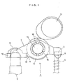
- a reference numeral 1 designates a rocker arm called an end pivot type.
- the rocker arm 1 is supported on its longitudinal one end side by a lash adjuster 2.
- the rocker arm 1 is tilted on the longitudinal one end side as a fulcrum by a cam 3.
- a valve 4 on longitudinal the other end side of the rocker arm 1 is opened and closed by the tilting operation of the cam 3.
- the rocker arm 1 includes two components, i.e., a body 5 and a roller 6.
- the body 5 is formed by guided-bending one metal plate into a substantially U shape in section by presswork.
- the body 5 includes side walls 7 and 8 in a pair and facing each other, a connecting wall 9 on a longitudinal one end side, and a connecting wall 10 on the longitudinal other end side.
- a valve fitting portion 11 for receiving an upper end of the valve 4 and recessed upward is provided.
- a pivot receiver 12 for receiving an upper end of the lash adjuster 2 and projecting into a hemispherical shape is provided.
- a through hole 13 is provided to side wall intermediate portions of the side walls 7 and 8 positioned between the connecting walls 9 and 10.
- the roller 6 is rotatibly supported through a spindle 14 and a plurality of needle rollers 15 between the side walls 7 and 8 facing each other of the body 5 in a state in which a portion of the roller 6 is projecting from the through hole 13.
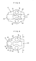
- a method of producing the body 5 will be described by reference to FIGS. 5 to 9.
- the through hole 13 is formed.
- Through holes 16, 16 through which the spindle passes are formed in the areas A2, A2.
- the area A1 is to be formed with the valve fitting portion 11.
- the overhanging chips 17, 17 are pressurized, compressed, and crushed toward the area A1 as shown in FIG. 6 by pinching end faces of the overhanging chips 17, 17 from longitudinal opposite sides.
- the pivot receiver 12 projecting upward into the hemispherical shape is formed.
- the pivot receiver 12 may be formed after the step of forming the valve fitting portion 11 and the guided-bending step of the metal plate A.
- valve fitting portion 11 recessed upward is formed in the area A1.
- a ceiling face of the valve fitting portion 11 is curved into a semicircular shape and this shape is formed by copying a shape of an end face of the lower die C.
- the areas A2, A2 which are on opposite sides of the area A1 of the metal plate A formed as described above are bent into a substantially U shape along one-dot dashed lines in FIG. 5 by carrying out guided-bending processing in directions of arrows by presswork by using a die D as shown in FIG. 9.
- the body 5 having the pair of side walls 7 and 8 and the connecting walls 9 and 10 can be obtained.
- the through hole 16 may be formed after the guided-bending processing of the opposite side walls 7 and 8.
- the pivot receiver 12 may be formed after the guided-bending processing of the opposite side walls 7 and 8.
- valve fitting portion 11 described above can be obtained by the half-punching processing in which the wall thickness of the one connecting wall 9 is increased and recessed upward, defects such as cracking or sinking from which the prior art suffer do not generate. Therefore, variations in strength and accuracy of the shape caused by the defects can be eliminated.
- valve fitting portion 11 Because an inner face of the valve fitting portion 11 is obtained by shearing in the half-punching processing, it is possible to more accurately control a width W of the valve fitting portion 11 and to stabilize operability and improve stability of operation of the valve 4 by the valve fitting portion 11.
- the overhanging chips 17, 17 are crushed to increase the wall thickness of the one connecting wall 9, it is possible to avoid reduction of rigidity of the connecting wall 9. Therefore, it is unnecessary to use a metal plate A with a large wall thickness. Because an amount of increase in the wall thickness can be increased or reduced by adjusting sizes of the overhanging chips 17, 17, a degree of freedom in design can be increased.
- FIGS. 10 to 17 Another embodiment of the present invention will be described by reference to FIGS. 10 to 17.
- a reference numeral 1 designates a rocker arm, 2 a lash adjuster, 3 a cam, 4 a valve, 5 a body, 6 a roller, 7 and 8 side walls, 9 and 10 connecting walls, 11 a valve fitting portion, 12 a pivot receiver, 13 a through hole, 14 a spindle, and 15 needle rollers.
- An upper face of the one connecting wall 9 provided with the valve fitting portion 11 is higher than an upper face of the other connecting wall 10 provided with the pivot receiver 12 by a necessary amount h.
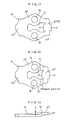
- a method of producing the body 5 shown in FIG. 10 will be described by reference to FIGS. 11 to 17.
- die-cutting processing is applied by presswork to one metal plate to obtain a metal plate A having an outside shape as shown in FIG. 11.
- the through hole 13, insertion holes 16, 16, and overhanging chips 17, 17 are formed on the metal plate A.
- an area A1 to be formed with the valve fitting portion 11 is bent into a stepped shape that is stepped upward by a height difference h from other areas.
- the height difference is determined based on a deviation of an upper end position of the valve 4 and an upper end position of the lash adjuster 2 from each other and generated according to an object for which the rocker arm is used.
- the body 5 in which the valve fitting portion 11 is formed in the higher position than the pivot receiver 12 can be obtained by simple processing of bending the connecting walls 9 and 10 into the stepped shape.
- overhanging chips 17, 17 are formed only at two sides facing each other of the area A1 which will be the connecting wall 9 to increase the wall thickness of the connecting wall 9 in the above embodiment, it is also possible to form overhanging chips also in the areas A2, A2 positioned on opposite sides of the area A1 and to pressurize and compress the respective overhanging chips from four directions to increase the wall thickness of the area A1.
- roller 6 is supported on the spindle 13 through the plurality of needle rollers 14 in the above embodiments, the roller 6 may be rotatibly supported by sliding contact without using the needle rollers 14. In other words, the roller 6 may be directly fitted over the spindle 13 by clearance fit or may be fitted with the spindle 13 through a slide bearing such as a bushing.
- the overhanging chips 17, 17 are crushed to increase the wall thickness of the connecting wall 9 in the above embodiment, it is also possible to pressurize and compress the areas A2, A2 in the wall thickness direction and to cause the areas A2, A2 to plastically flow into the area A1 to increase the wall thickness of the area A1 without forming the overhanging chips 17, 17.
- rocker arm 1 of the end pivot type is shown as an example in the above embodiment, the present invention can be applied also to a rocker arm of a center pivot type (not shown).
- the present invention can be used satisfactorily as a rocker arm tilted by a cam to open and close a valve provided to a cylinder head.
Landscapes
- Engineering & Computer Science (AREA)
- Mechanical Engineering (AREA)
- General Engineering & Computer Science (AREA)
- Valve-Gear Or Valve Arrangements (AREA)
Abstract
Description
Claims (12)
- A rocker arm tilted by a cam to open and close a valve provided to a cylinder head,wherein said rocker arm comprises a body obtained by bending one metal plate into a substantially U shape in section to form side walls in a pair and facing each other and a connecting wall for connecting said opposite side walls; anda roller mounted for rotation and for coming into contact with said cam between said opposite side walls of said body,a wall thickness of said connecting wall of said body is increased by flowing of a wall portion of a peripheral portion of said connecting wall, and recessing processing is applied to a lower face of said thickened connecting wall to form a valve fitting portion.
- The rocker arm according to claim 1, wherein flowing of said wall portion of said peripheral portion toward said connecting wall is caused by pressurizing and compressing said peripheral portion.
- The rocker arm according to claim 1, wherein said recessing processing is half-punching processing by presswork.
- The rocker arm according to claim 1, wherein only one face side of said connecting wall is caused to bulge by said wall thickening.
- A rocker arm tilted by a cam to open and close a valve provided to a cylinder head,wherein said rocker arm comprises a body obtained by applying guided-bending processing to one metal plate into a substantially U shape in section to form side walls in a pair and facing each other and connecting walls for respectively connecting longitudinal opposite end sides of said opposite side walls anda roller mounted for rotation and for coming into contact with said cam between said opposite side walls of said body,a lower face of one of said connecting walls of said body is recessed to form a valve fitting portion for receiving an upper end of said valve and a lower face of the other connecting wall is formed with a pivot receiver for receiving an upper end of a lash adjuster, andsaid valve fitting portion is formed by wall-thickening said one connecting wall by pressurizing and compressing a peripheral portion of said one connecting wall and by applying recessing processing to a lower face of said thickened wall portion.
- A rocker arm tilted by a cam to open and close a valve provided to a cylinder head,wherein said rocker arm comprises a body obtained by bending one metal plate into a substantially U shape in section to form side walls in a pair and facing each other and a connecting wall for connecting said opposite side walls anda roller mounted for rotation and for coming into contact with said cam between said opposite side walls of said body,a wall thickness of said connecting wall of said body is increased by flowing of a wall portion of a peripheral portion of said connecting wall by pressurizing and compressing said peripheral portion and recessing processing is applied to a lower face of said thickened connecting wall to form a valve fitting portion,said metal plate has areas to be formed with said side walls and an area to be formed with said connecting wall and has a overhanging chip at a periphery of said area to be formed with said connecting wall, and said overhanging chip is used as said peripheral portion.
- A rocker arm tilted by a cam to open and close a valve provided to a cylinder head,wherein said rocker arm comprises a body obtained by bending one metal plate into a substantially U shape to form side walls in a pair and facing each other and a connecting wall for connecting said opposite side walls anda roller mounted for rotation and for coming into contact with said cam between said opposite side walls of said body,an upper face of a longitudinal one end side area of said connecting wall is disposed in a higher position than an upper face of longitudinal the other end side area in a stepped manner,a wall thickness on a longitudinal one end side of said connecting wall is increased only toward a lower face side by gathering a wall portion from a peripheral portion of said connecting wall, and a valve fitting portion is formed to be recessed upward in said lower face of said connecting wall.
- A rocker arm tilted by a cam to open and close a valve provided to a cylinder head,wherein said rocker arm comprises a body obtained by applying guided-bending processing to one metal plate into a substantially U shape in section to form side walls in a pair and facing each other and connecting walls for respectively connecting longitudinal opposite end sides of said opposite side walls anda roller mounted for rotation and for coming into contact with said cam between said opposite side walls of said body,a lower face of one of said connecting walls of said body is recessed to form a valve fitting portion for receiving an upper end of said valve and a lower face of the other connecting wall is formed with a pivot receiver for receiving an upper end of a lash adjuster,said valve fitting portion is disposed in a higher position than said pivot receiver, andsaid valve fitting portion is formed by wall-thickening said one connecting wall by pressurizing and compressing a peripheral portion of said one connecting wall and by applying recessing processing to a lower face of said thickened wall portion.
- A method of producing a body of a rocker arm including said body obtained by bending one metal plate into a substantially U shape in section to form side walls in a pair and facing each other and a connecting wall for connecting said opposite side walls and having at a lower face of said connecting wall a valve fitting portion,wherein said method comprises the steps of punching said one metal plate into a necessary shape having an area to be formed with said valve fitting portion,wall thickening for increasing a wall thickness of said area by pressurizing, compressing, and crushing a periphery of said area from an end face in said metal plate punched in said punching to gather a plastically flowing wall portion into said area,recessing by presswork one face of said area thickened in said wall thickening to obtain said valve fitting portion recessed upward, andbending said metal plate such that opposite side portions of said area formed with said valve fitting portion in said metal plate stand in the same direction as a recessed direction of said valve fitting portion to obtain a pair of side walls.
- A method of producing a body of a rocker arm according to claim 9,wherein said metal plate is punched in said punching into a shape having overhanging chips that are to be crushed for wall thickening of said area to be formed with said valve fitting portion at two sides facing each other of said area andsaid opposite overhanging chips are pressurized, compressed, and crushed from end faces of said overhanging chips in said wall thickening to cause wall portions of said overhanging chips to plastically flow toward said area.
- The method of producing a body of a rocker arm according to claim 9, wherein said metal plate is thickened in said wall thickening such that one face side of said metal plate bulge.
- A method of producing a body of a rocker arm including said body obtained by bending one metal plate into a substantially U shape in section to form side walls in a pair and facing each other and a connecting wall for connecting said opposite side walls and having at a lower face of said connecting wall a valve fitting portion,wherein said method comprises the steps of punching said one metal plate into a necessary shape having an area to be formed with said valve fitting portion,bending said one metal plate punched into said necessary shape in said punching such that said area is stepped toward one side in a wall thickness direction,wall thickening for increasing a wall thickness of said area by pressurizing and compressing a periphery of said area to be formed with said valve fitting portion to gather a plastically flowing wall portion from said periphery to the other side in said wall thickness direction of said area,recessing by presswork said thickened portion of said area to obtain said valve fitting portion recessed upward, andbending said metal plate such that opposite side portions of said area formed with said valve fitting portion stand in the same direction as a recessed direction of said valve fitting portion to obtain a pair of side walls.
Applications Claiming Priority (5)
| Application Number | Priority Date | Filing Date | Title |
|---|---|---|---|
| JP23146499 | 1999-08-18 | ||
| JP23146399A JP4099909B2 (en) | 1999-08-18 | 1999-08-18 | Rocker arm body manufacturing method |
| JP23146399 | 1999-08-18 | ||
| JP23146499A JP4174138B2 (en) | 1999-08-18 | 1999-08-18 | ROCKER ARM AND ROCKER ARM BODY MANUFACTURING METHOD |
| PCT/JP2000/005456 WO2001012957A1 (en) | 1999-08-18 | 2000-08-14 | Rocker arm and method of manufacturing rocker arm body |
Publications (3)
| Publication Number | Publication Date |
|---|---|
| EP1122408A1 true EP1122408A1 (en) | 2001-08-08 |
| EP1122408A4 EP1122408A4 (en) | 2006-06-07 |
| EP1122408B1 EP1122408B1 (en) | 2009-03-04 |
Family
ID=26529887
Family Applications (1)
| Application Number | Title | Priority Date | Filing Date |
|---|---|---|---|
| EP00951997A Expired - Lifetime EP1122408B1 (en) | 1999-08-18 | 2000-08-14 | Rocker arm and method of manufacturing rocker arm body |
Country Status (5)
| Country | Link |
|---|---|
| US (1) | US6523514B1 (en) |
| EP (1) | EP1122408B1 (en) |
| KR (1) | KR20010078743A (en) |
| DE (1) | DE60041688D1 (en) |
| WO (1) | WO2001012957A1 (en) |
Cited By (11)
| Publication number | Priority date | Publication date | Assignee | Title |
|---|---|---|---|---|
| DE10218026A1 (en) * | 2002-04-23 | 2003-11-20 | Ina Schaeffler Kg | Lever-type cam follower for valve train of engine, has one end narrower than rest of cam follower length, in which side walls at one end of cam follower have smaller mean wall thickness than over rest of cam follower length |
| EP1375829A1 (en) * | 2002-06-26 | 2004-01-02 | Koyo Seiko Co., Ltd. | Rocker arm and manufacturing method thereof |
| EP1375830A1 (en) * | 2002-06-26 | 2004-01-02 | Koyo Seiko Co., Ltd. | Rocker arm and its manufacturing method |
| WO2005021183A1 (en) * | 2003-08-27 | 2005-03-10 | Gen Tek Technologies Marketing, Inc. | A method and system for forming a cam-engaged rocker arm |
| EP1380368A4 (en) * | 2001-04-19 | 2006-08-02 | Nsk Ltd | Metal plate rocker arm and method of manufacturing the metal plate rocker arm |
| WO2006112397A1 (en) | 2005-04-14 | 2006-10-26 | Jtekt Corporation | Rocker arm |
| DE102006002994A1 (en) * | 2006-01-21 | 2007-08-02 | Schaeffler Kg | Lever-like cam follower |
| EP1357257A3 (en) * | 2002-04-22 | 2007-09-19 | Schaeffler KG | Rocker arm made of sheet metal |
| EP1471214A4 (en) * | 2002-02-01 | 2010-08-04 | Nsk Ltd | Cam follower provided with rocker arm made of sheet metal |
| US7836860B2 (en) | 2007-11-21 | 2010-11-23 | Charter Manufacturing Co., Inc. | Engine rocker arm |
| WO2014135159A1 (en) * | 2013-03-08 | 2014-09-12 | Schaeffler Technologies Gmbh & Co. Kg | Cam follower for a valve train of an internal combustion engine |
Families Citing this family (4)
| Publication number | Priority date | Publication date | Assignee | Title |
|---|---|---|---|---|
| US6807932B2 (en) * | 2001-11-22 | 2004-10-26 | Ntn Corporation | Rocker arm |
| DE102004018387A1 (en) * | 2004-04-16 | 2005-11-03 | Ina-Schaeffler Kg | Impact-pressed lever for the valve control of a piston engine and method for its production |
| US20060185636A1 (en) * | 2005-02-23 | 2006-08-24 | Gen Tek Technologies Marketing, Inc. | Manufacturing a rocker lever using cold forming and welding |
| JP6769691B2 (en) * | 2014-12-26 | 2020-10-14 | 株式会社オティックス | Rocker arm manufacturing method |
Family Cites Families (25)
| Publication number | Priority date | Publication date | Assignee | Title |
|---|---|---|---|---|
| GB2115898A (en) | 1982-03-02 | 1983-09-14 | Colin Thomas Pomfret | A device for transmitting movement |
| US4614171A (en) * | 1985-07-05 | 1986-09-30 | W H Industries Inc. | Rocker arm construction |
| US4628874A (en) | 1985-10-30 | 1986-12-16 | Eaton Corporation | Roller follower axle retention |
| JPH0191931A (en) * | 1987-10-01 | 1989-04-11 | Mitsubishi Metal Corp | Production of rocker arm |
| US4829647A (en) * | 1987-12-14 | 1989-05-16 | Ford Motor Company | Method of making low friction finger follower rocker arms |
| US4825717A (en) * | 1988-09-12 | 1989-05-02 | Henley Manufacturing Corporation | Rocker arm of the cam-follower type with ribs |
| JP2724415B2 (en) * | 1989-11-29 | 1998-03-09 | 光洋精工株式会社 | Method of manufacturing steel plate rocker arm |
| US5016582A (en) | 1990-10-12 | 1991-05-21 | Henley Manufacturing Holding Company, Inc. | Rocker arm |
| DE69309346T2 (en) * | 1992-01-07 | 1997-07-10 | Koyo Seiko Co | ROCKER LEVER WITH ROLLER AND THEIR PRODUCTION PROCESS |
| JPH05272310A (en) * | 1992-03-27 | 1993-10-19 | Ntn Corp | Roller rocker arm and manufacture thereof |
| JPH0617614A (en) | 1992-07-03 | 1994-01-25 | Kubota Corp | Swing-arm knuckle-supported valve train for overhead valve engine |
| DE4234868C2 (en) * | 1992-10-16 | 1999-10-28 | Schaeffler Waelzlager Ohg | Process for the production of a rocker arm or rocker arm |
| JP2879511B2 (en) * | 1993-07-07 | 1999-04-05 | 光洋精工株式会社 | Press-made rocker arm and method of manufacturing the same |
| JP3306478B2 (en) | 1993-11-29 | 2002-07-24 | 光洋精工株式会社 | Pressed rocker arm |
| JPH07259512A (en) * | 1994-03-18 | 1995-10-09 | Koyo Seiko Co Ltd | Rocker arm |
| US5720245A (en) * | 1995-11-13 | 1998-02-24 | Sandco Automotive Limited | Finger follower arm |
| DE19652676A1 (en) | 1996-12-18 | 1998-06-25 | Schaeffler Waelzlager Ohg | Actuating lever for a valve train of an internal combustion engine |
| JP3000346B2 (en) * | 1997-04-15 | 2000-01-17 | 株式会社久保田鉄工所 | Manufacturing method of flywheel |
| US5819694A (en) | 1997-05-15 | 1998-10-13 | Welles Manufacturing Company | Stamped roller-type cam followers with added height |
| DE19721210A1 (en) * | 1997-05-21 | 1998-11-26 | Schaeffler Waelzlager Ohg | One-piece, swarflessly formed tractive lever for internal combustion engine valve gear |
| JP2000120411A (en) * | 1998-03-12 | 2000-04-25 | Nsk Ltd | Sheet metal rocker arm and method of manufacturing the same |
| US6199527B1 (en) * | 1998-03-12 | 2001-03-13 | Nsk Ltd. | Sheet metal rocker arm, manufacturing method thereof, cam follower with said rocker arm, and assembling method thereof |
| JP3497373B2 (en) | 1998-03-25 | 2004-02-16 | 中西金属工業株式会社 | Rocker arm and method of manufacturing the same |
| JP3497374B2 (en) * | 1998-03-25 | 2004-02-16 | 中西金属工業株式会社 | Rocker arm and method of manufacturing the same |
| JP3172506B2 (en) | 1999-03-18 | 2001-06-04 | 株式会社東芝 | Permanent magnet type reluctance type rotating electric machine |
-
2000
- 2000-08-14 EP EP00951997A patent/EP1122408B1/en not_active Expired - Lifetime
- 2000-08-14 KR KR1020007014704A patent/KR20010078743A/en active Pending
- 2000-08-14 DE DE60041688T patent/DE60041688D1/en not_active Expired - Lifetime
- 2000-08-14 WO PCT/JP2000/005456 patent/WO2001012957A1/en not_active Ceased
- 2000-08-14 US US09/743,868 patent/US6523514B1/en not_active Expired - Lifetime
Cited By (16)
| Publication number | Priority date | Publication date | Assignee | Title |
|---|---|---|---|---|
| EP1380368A4 (en) * | 2001-04-19 | 2006-08-02 | Nsk Ltd | Metal plate rocker arm and method of manufacturing the metal plate rocker arm |
| EP1471214A4 (en) * | 2002-02-01 | 2010-08-04 | Nsk Ltd | Cam follower provided with rocker arm made of sheet metal |
| EP1357257A3 (en) * | 2002-04-22 | 2007-09-19 | Schaeffler KG | Rocker arm made of sheet metal |
| DE10218026A1 (en) * | 2002-04-23 | 2003-11-20 | Ina Schaeffler Kg | Lever-type cam follower for valve train of engine, has one end narrower than rest of cam follower length, in which side walls at one end of cam follower have smaller mean wall thickness than over rest of cam follower length |
| US6889643B2 (en) | 2002-06-26 | 2005-05-10 | Koyo Seiko Co., Ltd. | Rocker arm and manufacturing method thereof |
| US7043836B2 (en) | 2002-06-26 | 2006-05-16 | Koyo Seiko Co., Ltd. | Manufacturing method of rocker arm |
| EP1375830A1 (en) * | 2002-06-26 | 2004-01-02 | Koyo Seiko Co., Ltd. | Rocker arm and its manufacturing method |
| EP1375829A1 (en) * | 2002-06-26 | 2004-01-02 | Koyo Seiko Co., Ltd. | Rocker arm and manufacturing method thereof |
| WO2005021183A1 (en) * | 2003-08-27 | 2005-03-10 | Gen Tek Technologies Marketing, Inc. | A method and system for forming a cam-engaged rocker arm |
| WO2006112397A1 (en) | 2005-04-14 | 2006-10-26 | Jtekt Corporation | Rocker arm |
| EP1870567A4 (en) * | 2005-04-14 | 2009-11-18 | Jtekt Corp | Rocker arm |
| US7694659B2 (en) | 2005-04-14 | 2010-04-13 | Jtekt Corporation | Rocker arm |
| DE102006002994A1 (en) * | 2006-01-21 | 2007-08-02 | Schaeffler Kg | Lever-like cam follower |
| US7836860B2 (en) | 2007-11-21 | 2010-11-23 | Charter Manufacturing Co., Inc. | Engine rocker arm |
| WO2014135159A1 (en) * | 2013-03-08 | 2014-09-12 | Schaeffler Technologies Gmbh & Co. Kg | Cam follower for a valve train of an internal combustion engine |
| US9556755B2 (en) | 2013-03-08 | 2017-01-31 | Schaeffler Technologies AG & Co. KG | Cam follower for a valve train of an internal combustion engine |
Also Published As
| Publication number | Publication date |
|---|---|
| KR20010078743A (en) | 2001-08-21 |
| WO2001012957A1 (en) | 2001-02-22 |
| US6523514B1 (en) | 2003-02-25 |
| EP1122408B1 (en) | 2009-03-04 |
| DE60041688D1 (en) | 2009-04-16 |
| EP1122408A4 (en) | 2006-06-07 |
Similar Documents
| Publication | Publication Date | Title |
|---|---|---|
| US6523514B1 (en) | Rocker arm and method of manufacturing rocker arm body | |
| US5642693A (en) | Rocker arm and method of manufacturing same | |
| KR100653656B1 (en) | Method of manufacturing rocker arm and rocker arm body | |
| US5678305A (en) | Method for manufacturing a rocker arm with a roller | |
| KR0178813B1 (en) | Rocker arm formed by pressing | |
| US5720245A (en) | Finger follower arm | |
| US7043836B2 (en) | Manufacturing method of rocker arm | |
| JP4174138B2 (en) | ROCKER ARM AND ROCKER ARM BODY MANUFACTURING METHOD | |
| JP4099909B2 (en) | Rocker arm body manufacturing method | |
| JPH05272310A (en) | Roller rocker arm and manufacture thereof | |
| EP0849436A1 (en) | Finger follower arm | |
| US11143060B2 (en) | Rocker arm and method of manufacturing the same | |
| US7797830B2 (en) | Method of making an outer lever of a switchable finger lever | |
| JPH07229407A (en) | Rocker arm | |
| JP4227718B2 (en) | Rocker arm manufacturing method | |
| JP3302395B2 (en) | Roller tappet | |
| JP2001355413A (en) | Rocker arm | |
| JPH041402A (en) | Valve lifter | |
| JP2001003714A (en) | Rocker arm | |
| JPS59185533A (en) | Manufacturing method of plunger for valve brush adjuster | |
| JP2001065313A (en) | Rocker arm and method of manufacturing the same | |
| JP2003097226A (en) | Rocker arm and method of forming oil hole in pivot portion in the rocker arm | |
| JP2003166405A (en) | Rocker arm | |
| JPH07259512A (en) | Rocker arm | |
| JP2004190516A (en) | Rocker arm |
Legal Events
| Date | Code | Title | Description |
|---|---|---|---|
| PUAI | Public reference made under article 153(3) epc to a published international application that has entered the european phase |
Free format text: ORIGINAL CODE: 0009012 |
|
| AK | Designated contracting states |
Kind code of ref document: A1 Designated state(s): AT BE CH CY DE DK ES FI FR GB GR IE IT LI LU MC NL PT SE |
|
| AX | Request for extension of the european patent |
Free format text: AL;LT;LV;MK;RO;SI |
|
| 17P | Request for examination filed |
Effective date: 20011106 |
|
| RBV | Designated contracting states (corrected) |
Designated state(s): DE FR GB |
|
| A4 | Supplementary search report drawn up and despatched |
Effective date: 20060426 |
|
| RAP1 | Party data changed (applicant data changed or rights of an application transferred) |
Owner name: JTEKT CORPORATION |
|
| 17Q | First examination report despatched |
Effective date: 20071029 |
|
| GRAP | Despatch of communication of intention to grant a patent |
Free format text: ORIGINAL CODE: EPIDOSNIGR1 |
|
| GRAS | Grant fee paid |
Free format text: ORIGINAL CODE: EPIDOSNIGR3 |
|
| GRAA | (expected) grant |
Free format text: ORIGINAL CODE: 0009210 |
|
| AK | Designated contracting states |
Kind code of ref document: B1 Designated state(s): DE FR GB |
|
| REG | Reference to a national code |
Ref country code: GB Ref legal event code: FG4D |
|
| REF | Corresponds to: |
Ref document number: 60041688 Country of ref document: DE Date of ref document: 20090416 Kind code of ref document: P |
|
| PLBE | No opposition filed within time limit |
Free format text: ORIGINAL CODE: 0009261 |
|
| STAA | Information on the status of an ep patent application or granted ep patent |
Free format text: STATUS: NO OPPOSITION FILED WITHIN TIME LIMIT |
|
| 26N | No opposition filed |
Effective date: 20091207 |
|
| REG | Reference to a national code |
Ref country code: FR Ref legal event code: PLFP Year of fee payment: 17 |
|
| REG | Reference to a national code |
Ref country code: FR Ref legal event code: PLFP Year of fee payment: 18 |
|
| REG | Reference to a national code |
Ref country code: FR Ref legal event code: PLFP Year of fee payment: 19 |
|
| PGFP | Annual fee paid to national office [announced via postgrant information from national office to epo] |
Ref country code: FR Payment date: 20190711 Year of fee payment: 20 Ref country code: DE Payment date: 20190730 Year of fee payment: 20 |
|
| PGFP | Annual fee paid to national office [announced via postgrant information from national office to epo] |
Ref country code: GB Payment date: 20190816 Year of fee payment: 20 |
|
| REG | Reference to a national code |
Ref country code: DE Ref legal event code: R071 Ref document number: 60041688 Country of ref document: DE |
|
| REG | Reference to a national code |
Ref country code: GB Ref legal event code: PE20 Expiry date: 20200813 |
|
| PG25 | Lapsed in a contracting state [announced via postgrant information from national office to epo] |
Ref country code: GB Free format text: LAPSE BECAUSE OF EXPIRATION OF PROTECTION Effective date: 20200813 |