EP1659338A1 - Gasturbinenbrennkammer mit Hohlraum zur Erzeugung eingeschlossener Wirbel - Google Patents
Gasturbinenbrennkammer mit Hohlraum zur Erzeugung eingeschlossener Wirbel Download PDFInfo
- Publication number
- EP1659338A1 EP1659338A1 EP05254296A EP05254296A EP1659338A1 EP 1659338 A1 EP1659338 A1 EP 1659338A1 EP 05254296 A EP05254296 A EP 05254296A EP 05254296 A EP05254296 A EP 05254296A EP 1659338 A1 EP1659338 A1 EP 1659338A1
- Authority
- EP
- European Patent Office
- Prior art keywords
- fuel
- combustion
- chamber
- air
- air mixture
- Prior art date
- Legal status (The legal status is an assumption and is not a legal conclusion. Google has not performed a legal analysis and makes no representation as to the accuracy of the status listed.)
- Withdrawn
Links
- 238000002485 combustion reaction Methods 0.000 claims abstract description 154
- 239000000446 fuel Substances 0.000 claims abstract description 80
- 239000000203 mixture Substances 0.000 claims abstract description 80
- 238000000034 method Methods 0.000 claims abstract description 38
- 239000000567 combustion gas Substances 0.000 claims description 36
- 238000009792 diffusion process Methods 0.000 claims description 20
- 239000007789 gas Substances 0.000 description 25
- 230000008569 process Effects 0.000 description 10
- 230000000712 assembly Effects 0.000 description 9
- 238000000429 assembly Methods 0.000 description 9
- IJGRMHOSHXDMSA-UHFFFAOYSA-N Atomic nitrogen Chemical compound N#N IJGRMHOSHXDMSA-UHFFFAOYSA-N 0.000 description 6
- 239000000047 product Substances 0.000 description 6
- 238000005273 aeration Methods 0.000 description 5
- CURLTUGMZLYLDI-UHFFFAOYSA-N Carbon dioxide Chemical compound O=C=O CURLTUGMZLYLDI-UHFFFAOYSA-N 0.000 description 4
- UGFAIRIUMAVXCW-UHFFFAOYSA-N Carbon monoxide Chemical compound [O+]#[C-] UGFAIRIUMAVXCW-UHFFFAOYSA-N 0.000 description 4
- ATUOYWHBWRKTHZ-UHFFFAOYSA-N Propane Chemical compound CCC ATUOYWHBWRKTHZ-UHFFFAOYSA-N 0.000 description 4
- 229910002091 carbon monoxide Inorganic materials 0.000 description 4
- VNWKTOKETHGBQD-UHFFFAOYSA-N methane Chemical compound C VNWKTOKETHGBQD-UHFFFAOYSA-N 0.000 description 4
- 229910052757 nitrogen Inorganic materials 0.000 description 3
- VEMKTZHHVJILDY-UHFFFAOYSA-N resmethrin Chemical compound CC1(C)C(C=C(C)C)C1C(=O)OCC1=COC(CC=2C=CC=CC=2)=C1 VEMKTZHHVJILDY-UHFFFAOYSA-N 0.000 description 3
- XLYOFNOQVPJJNP-UHFFFAOYSA-N water Substances O XLYOFNOQVPJJNP-UHFFFAOYSA-N 0.000 description 3
- 206010016754 Flashback Diseases 0.000 description 2
- 238000010793 Steam injection (oil industry) Methods 0.000 description 2
- 230000015572 biosynthetic process Effects 0.000 description 2
- 229910002092 carbon dioxide Inorganic materials 0.000 description 2
- 239000001569 carbon dioxide Substances 0.000 description 2
- 238000001816 cooling Methods 0.000 description 2
- 238000003780 insertion Methods 0.000 description 2
- 230000037431 insertion Effects 0.000 description 2
- 239000000463 material Substances 0.000 description 2
- 239000003345 natural gas Substances 0.000 description 2
- 239000001294 propane Substances 0.000 description 2
- 230000001105 regulatory effect Effects 0.000 description 2
- QVGXLLKOCUKJST-UHFFFAOYSA-N atomic oxygen Chemical compound [O] QVGXLLKOCUKJST-UHFFFAOYSA-N 0.000 description 1
- 230000009286 beneficial effect Effects 0.000 description 1
- 238000006243 chemical reaction Methods 0.000 description 1
- 239000013066 combination product Substances 0.000 description 1
- 229940127555 combination product Drugs 0.000 description 1
- 238000004891 communication Methods 0.000 description 1
- 238000010276 construction Methods 0.000 description 1
- 230000001276 controlling effect Effects 0.000 description 1
- 230000003247 decreasing effect Effects 0.000 description 1
- 238000013461 design Methods 0.000 description 1
- 230000000694 effects Effects 0.000 description 1
- 239000003344 environmental pollutant Substances 0.000 description 1
- 239000012530 fluid Substances 0.000 description 1
- 239000001257 hydrogen Substances 0.000 description 1
- 229910052739 hydrogen Inorganic materials 0.000 description 1
- 125000004435 hydrogen atom Chemical class [H]* 0.000 description 1
- 239000003350 kerosene Substances 0.000 description 1
- 239000007788 liquid Substances 0.000 description 1
- 230000007246 mechanism Effects 0.000 description 1
- 239000001301 oxygen Substances 0.000 description 1
- 229910052760 oxygen Inorganic materials 0.000 description 1
- 230000037361 pathway Effects 0.000 description 1
- 231100000719 pollutant Toxicity 0.000 description 1
- 239000011148 porous material Substances 0.000 description 1
- 238000010791 quenching Methods 0.000 description 1
- 230000000171 quenching effect Effects 0.000 description 1
- 230000009467 reduction Effects 0.000 description 1
- 238000012546 transfer Methods 0.000 description 1
Images


Classifications
-
- F—MECHANICAL ENGINEERING; LIGHTING; HEATING; WEAPONS; BLASTING
- F23—COMBUSTION APPARATUS; COMBUSTION PROCESSES
- F23R—GENERATING COMBUSTION PRODUCTS OF HIGH PRESSURE OR HIGH VELOCITY, e.g. GAS-TURBINE COMBUSTION CHAMBERS
- F23R3/00—Continuous combustion chambers using liquid or gaseous fuel
- F23R3/28—Continuous combustion chambers using liquid or gaseous fuel characterised by the fuel supply
- F23R3/34—Feeding into different combustion zones
- F23R3/346—Feeding into different combustion zones for staged combustion
-
- F—MECHANICAL ENGINEERING; LIGHTING; HEATING; WEAPONS; BLASTING
- F23—COMBUSTION APPARATUS; COMBUSTION PROCESSES
- F23R—GENERATING COMBUSTION PRODUCTS OF HIGH PRESSURE OR HIGH VELOCITY, e.g. GAS-TURBINE COMBUSTION CHAMBERS
- F23R3/00—Continuous combustion chambers using liquid or gaseous fuel
- F23R3/28—Continuous combustion chambers using liquid or gaseous fuel characterised by the fuel supply
- F23R3/286—Continuous combustion chambers using liquid or gaseous fuel characterised by the fuel supply having fuel-air premixing devices
Definitions
- the present invention relates generally to fuel aeration and combustion with respect to a combustion device, such as a gas turbine device.
- Traditional gas turbine devices air is drawn from the environment, mixed with fuel and, subsequently, ignited to produce combustion gases, which may be used to drive a machine element or to generate power, for instance.
- Traditional gas turbine devices generally include three main systems: a compressor, a combustor and a turbine.
- the compressor pressurizes air and sends this air towards the combustor.
- the combustor can be configured as multiple can combustors or as an annulus in direct fluid communication with the turbine.
- the compressed air and the fuel are mixed and burnt in the combustor, and the resulting combustion gases actuate a turbine, generating power or driving a machine element, for instance. That is, the combustion gases flow across a turbine and actuate the turbine that, in turn, drives a shaft to power the compressor and produces output power for powering an electrical generator or for powering an aircraft, to name but few examples.
- Gas turbine engines are typically operated for extended periods of time, and exhaust emissions from the combustion gases are a concern, often subject to regulatory limits. For example, during combustion, nitrogen combines with oxygen to produce oxides of nitrogen (NOx), and these NOx emissions are often subject to regulatory limits and are generally undesired.
- NOx oxides of nitrogen
- gas turbine devices reduce the amount of NOx emissions by decreasing the fuel-to-air ratio, and these devices are often referred to as lean devices.
- Lean device reduce the combustion temperature within the combustion chamber and, in turn, reduce the amount of NOx emissions produced during combustion.
- traditional lean combustion devices are susceptible to combustion instabilities that cause the fuel-to-air mixture to vary and are also susceptible to inefficiencies that increase carbon monoxide (CO) emissions, for instance.
- CO carbon monoxide
- stage the introduction of fuel to the combustor This reduces the time at the highest temperature and makes the head end of the combustor leaner. Again, the problems associated with very lean premixing can be limiting. The tendency of the staged fuel to burn rich is also limiting.
- the present invention provides a combustor assembly for use in a gas-turbine device.
- the combustor assembly includes a first combustion zone and a second combustion zone.
- the combustor assembly further includes a first premix chamber configured to receive a fuel and air to facilitate a first fuel-air mixture having a first fuel-to-air ratio, wherein the first premix chamber is fluidiclly coupled to the combustion chamber at the first combustion zone.
- the combustor assembly also includes a second premix chamber configured to receive a fuel and air to facilitate a second fuel-air mixture having a second fuel-to-air ratio, wherein the second premix chamber is fluidiclly coupled to the combustion chamber at the second combustion zone, wherein the second combustion zone is radially outboard of the first combustion zone.
- the present invention provides an exemplary method of providing combustion gases for a gas-turbine device.
- the method includes supplying fuel and compressed air to a first premix chamber of a combustor assembly to produce a first fuel-air mixture having a first fuel-to-air ratio.
- the method includes routing the first fuel-air mixture to a first combustion zone of a combustion chamber of the combustor assembly.
- the method also includes supplying fuel and compressed air to a second premix chamber of the combustor assembly to produce a second fuel-air mixture having a second fuel-to-air ratio.
- the method further includes routing the second fuel-air mixture to a second combustion zone of the combustion chamber of the combustor assembly to generate a vortex flow of the second fuel-air mixture in the second combustion zone, wherein the second combustion zone is disposed radially outboard of the first combustion zone.
- the present technique is generally directed towards combustion in a gas turbine device.
- Gas turbine devices exemplary embodiments of which are discussed further below, are used in many applications, such as commercial aircrafts and power plants, to name but few applications.
- a gas turbine device works on the principle that liquid or gaseous fuel, such as propane, natural gas, syngas or kerosene to name but few types of fuel, is ignited in a combustion zone to produce combustion gases, and these combustion gases are used to actuate a turbine.
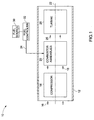
- the gas turbine device 10 includes an outer casing 12 that protects and secures the various internal components of the gas turbine device 10. Additionally, as discussed further below, the outer casing 12 provides a structure that directs airflow with respect to the gas turbine device 10.
- the exemplary gas turbine device 10 includes a compressor 14.
- the compressor 14 draws in air 16 from the atmosphere surrounding the gas turbine device 10 and, then, forces the air 16 downstream in the device. Resultantly, the compressor increases the pressure of the air.
- the compressor 14 compresses the air 16 in the environment, and, as such, increases its pressure to produce compressed air 18 and airflow.
- the compressor 14 acts as a source of compressed air throughout the device and, specifically, the combustors, as discussed further below.
- the compressor 14 is capable of increasing the pressure of the air 16 by a factor of 30, and beyond.
- the compressed air 18 is directed downstream into the device and into a plurality of combustor assemblies 20 (i.e., combustor cans) that are disposed concentrically about the longitudinal axis 22 of the gas turbine device 10.
- the combustor assemblies 20 have a generally cylindrical shape, however, other shapes are envisaged.
- the combustor assemblies 20 receive the compressed air 18 and fuel 24 and facilitate the formation of a fuel-air mixture.
- the combustor assemblies 20 ignite the fuel-air mixture to produce exhaust gases or combustion gases 26, which drive the turbine 28.
- the fuel 24 for the plurality of combustors 20 is provided by a fuel source 30.
- the fuel source 30 is a fuel manifold that directs fuel to the various combustor assemblies.
- the fuel source 30 i.e., the fuel manifold
- the fuel controller 32 is under the direction of a fuel controller 32.
- the delivery of fuel 24 to various components of the combustor assemblies 20 is controlled individually using a system of valves, for example.
- a desired quantities of fuel may be provided to various components in the combustor assembly 20 at a desired times and in a manner independent from one another.
- the combustion gases 26 flow through the turbine 28, and this flow drives the turbine 28.
- the rotation of the turbine 28 is harnessed to cause rotation of a generator rotor, for example, thereby producing power.
- the rotation of the turbine 28 may be harnessed to drive a machine element.
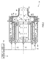
- FIG. 2 is a partial and diagrammatic, cross-sectional view of a single stage trapped vortex combustor assembly 34, in accordance with an exemplary embodiment of present technique. More specifically, FIG. 2 illustrates a detail portion of a combustor can or combustor assembly 34 similar to one of the combustor assemblies 20 discussed above in FIG. 1.
- the fuel source 30 and the fuel controller 32 direct fuel 24 into various distribution mechanisms and aeration chambers of the combustor assembly.
- the fuel 24 can be one of several possible fuel sources such as propane, natural gas, hydrogen, or syngas, and can include dilutes, such as nitrogen, steam or carbon dioxide (CO2). Of course, other types of fuels are also envisaged.
- fuel 24 is provided to a diffusion chamber 36, a primary premix chamber (e.g., first premix chamber 38), and a secondary premix chamber (e.g., second remix chamber 40) of the combustor assembly 34.
- a primary premix chamber e.g., first premix chamber 38
- a secondary premix chamber e.g., second remix chamber 40
- these regions provide the appropriate fuel or fuel-air mixtures to a combustion chamber 42, as discussed further below.
- Fuel 24 is provided to the combustion chamber 42, among other pathways, through the diffusion chamber 36.
- Fuel 24 from the plurality of inlet tubes 44 of the diffusion chamber 36 is introduced into a secondary combustion zone or second combustion zone 46 of the combustion chamber 42 via a plurality of apertures 48.
- the delivery of the diffusion fuel 24 through the plurality of apertures 48 is believed to minimize the thermal gradient with respect to the surfaces defining the combustion chamber 42.
- fuel 24 from the diffusion chamber 36 facilitates an increase in the richness of the fuel-air mixture in the combustion chamber 42, if such richness is desired and/or if conditions warrant.
- some of the introduced fuel 24 is aerated prior to insertion into the combustion chamber 42.
- fuel 24 travels through a plurality of inlet tubes 50 of the primary premix chamber 38. This aeration at least occurs partially in a first premix device 52.
- the premix device 52 mixes air and fuel 24 to produce a fuel-air mixture.
- compressed air which is originated at the compressor 14 (see FIG. 1), travels through an airflow chamber 56 and is then bifurcated into two portions, namely a first airflow portion 58 and a second airflow portion 60.
- the first airflow portion 58 of the compressed air enters the primary premix chamber 38.
- the premix device 52 facilitates aeration of the fuel 24; in other words, the premix device 52 facilitates mixing of the fuel 24 and the first airflow portion 58 to produce a primary fuel-air mixture or first fuel-air mixture 62 with a first fuel-to-air ratio.
- the flow of the first airflow portion 58 drives the primary fuel-air mixture 62 towards a plurality of apertures 64 and, in turn, into the combustion chamber 42.
- the plurality of apertures 64 is located towards the center of the combustion chamber 42 and feeds into a primary combustion zone or first combustion zone 66 of the combustion chamber 42, which is also located towards the center of the combustion chamber 42.
- fuel-air mixture from the primary premix chamber 38 is a relatively lean mixture.
- the exemplary combustor assembly 34 also includes a secondary aeration region, that is, the second premix chamber 40.
- Fuel 24 is provided to the secondary premix chamber 40 by way of a plurality of fuel tubes 68.
- compressed air travels through the airflow chamber 56, and the second airflow portion 60 of the compressed air then enters the secondary premix chamber 40.
- a second premix device 70 facilitates mixing of fuel 24 and the second airflow portion 60 to produce a secondary fuel-air mixture or a second fuel-air mixture 72 with a second fuel-to-air ratio.
- the second fuel-air mixture 72 has a higher fuel-to-air ratio than the first fuel-air mixture 62 produced in the primary premix chamber 38. That is, the fuel-air mixture 72 produced in the secondary premix chamber 40 is richer than that produced in the primary premix chamber 38.
- the compressed air 60 drives an airflow that pushes the fuel-air mixture 72 into the secondary combustion zone 46 of the combustion chamber 42 through a plurality of apertures 74.
- the second fuel-air mixture 72 is introduced into the secondary combustion zone 46, which is radially outboard of the primary combustion zone 66.
- the flow of the secondary fuel-air mixture and the design of the secondary premix zone facilitate avoiding flashbacks.
- the flashback is a process by which the flame travels in a direction opposite to a desired direction, i.e. the flame may travel from the combustion chamber towards the premix chambers.
- the second fuel-air mixture 72 As the second fuel-air mixture 72 is introduced into the combustion chamber, specifically in the secondary combustion zone 46, the second fuel-air mixture 72 begins to travel in a vortex-like manner.
- the introduced mixture i.e., second fuel-air mixture 72
- the U-shaped secondary combustion zone 46 This U-shape induces the vortex flow 76.
- fuel-air mixture 72 introduced from the inlet 74 travels axially across the secondary combustion zone 46 and impacts the opposite sidewall, causing the secondary fuel-air mixture 72 to travel back towards the inlet 74.
- the process repeats, and the vortex flow 76 is maintained.
- the exemplary assembly includes apertures 78 that facilitate the generation of vortex flow in the secondary combustion zone 46.
- the fuel-to-air ratio of the fuel-air mixture, which is subjected to vortex flow can be increased by the introduction of fuel 24 through the diffusion chamber 36 and its corresponding inlet 44.
- the premix chambers 38, 40 and the diffusion chamber 36 are separated from the combustion chamber 42 by an end plate assembly 80.
- the end plate assembly 80 includes a first disk 82 that is disposed between the combustion chamber 42 and the primary premix chamber 38, the diffusion chamber 36 and the secondary premix chamber 40 and a second disk 84 that circumscribes the first disk 82.
- the materials of the first and second disks in the exemplary embodiment, are varied with respect to one another to provide for materials that are best suited to the different operating climates, as discussed further below.
- the construction of the first disk 82 is more robust to accommodate the higher combustion temperatures in the combustion chamber.
- the fuel 24 through the diffusion chamber 36 is introduced into the secondary combustion zone 46 of the combustion chamber 42 and ignited by a first igniter 86 which is mounted over a combustion chamber wall 88.
- the combustor assemblies may include crossfire tubes instead of igniters in each combustor assembly.
- Crossfire tubes are tubes that transfer the flame due to ignition of fuel from one combustor assembly to another.
- fuel is ignited by an ignition source.
- the secondary fuel-air mixture 72 is introduced into the secondary combustion zone 46.
- the U-shape of the secondary combustion zone 46 creates the vortex flow 76 of the fuel-air mixture inside the secondary combustion zone 46.
- this vortex flow facilitates the mixing of the fuel 24 from the diffusion chamber 36 and the secondary fuel-air mixture 72 to produce a flame and combustion products, which may include uncombusted fuel and fuel-air mixture.
- the igniter 86 ignites the fuel subjected to vortex flow in the secondary combustion zone 46, as discussed above. It is believed that, in the combustion chamber 42, the ignited fuel-air mixture produces a flame and combustion product 90, which propagate into the primary combustion zone 66 and ignite the primary fuel-air mixture 62, which is a leaner mixture. The flame 90 acts as a pilot for the fuel-air mixture in the primary combustion zone 66.
- This flame is thought to provide a more stable combustion of the primary fuel-air mixture, and, as such, the flame facilitates lean and stable operation of the combustor assembly, thereby reducing the NOx emissions generated during combustion, for instance.
- the combination product 90 enters the primary combustion zone and affects the fuel-air mixture therein.
- the flow of fuel 24 to the diffusion chamber 36, the primary premix manifold 38, and the secondary premix manifold 40 is controlled to alter the quality and quantity of fuel-air mixture desired for a particular application.
- fuel 24 through the diffusion chamber 36 is provided to the combustion chamber 42 and ignited.
- the secondary fuel-air mixture 72 from the secondary premix chamber 40 is introduced and mixed with the fuel 24 inside the combustion chamber.
- the flame due to the ignition of the fuel 24 through the diffusion chamber 36 ignites the rich fuel-air mixture 72 entering through the secondary premix chamber 40.
- supply of fuel 24 through the diffusion chamber 36 is gradually reduced, and the flow of the secondary fuel-air mixture 72 through the secondary premix chamber 40 is gradually increased.
- lean fuel-air mixture is beneficial for reducing the emission of NOx.
- the lean fuel-air mixture 62 of primary premix chamber 38 is introduce into the combustion chamber 42 and ignited using the generated flame from the secondary combustion zone 46.
- various criteria for the effective functioning of the gas turbine device can be achieved.
- the combustion in the combustion chamber 42 results in first combustion gases 92, which flow towards the turbine.
- a plurality of apertures 94 on the combustion chamber wall 96 and a disk 100 facilitate airflow into the combustion chamber 42, which in-turn facilitates reducing the emissions of NOx.
- the combustion chamber walls 88 and 96 include an impingement layer 102.
- the impingement layer 102 has a plurality of pores that facilitates a flow of compressed air against the external combustion chamber walls, which, in turn, facilitates cooling of the combustion chamber walls.
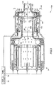
- FIG. 3 is a partial and diagrammatic, cross-sectional view of a two-stage trapped vortex combustor assembly 104, in accordance with an exemplary embodiment of present technique.
- the two-stage trapped vortex combustor assembly 104 includes the first stage trapped vortex combustor assembly 34 of FIG. 2, coupled to a second stage trapped vortex combustor assembly 106.
- the second stage trapped vortex combustor assembly 106 includes a combustion gas chamber 108, a third premix chamber 110 and a downstream combustion chamber 112.
- the second stage trapped vortex combustor assembly is located relatively close to a turbine inlet, to facilitate improved reduction of NOx emissions.
- the first combustion gases 92 from the first stage trapped vortex combustor assembly 34 travel towards the second stage trapped vortex combustor assembly 106. These combustion gases 92 flow through an opening 114 in an end plate 116 into the downstream combustion chamber 112.
- the second stage combustor assembly 106 also includes the third premix chamber 110.
- the fuel source 30 and the fuel controller 32 provide a fuel 24 to the inlet tubes 120 of the third premix chamber 110.
- Compressed air 122 travels through an air chamber 124 and enters the third premix chamber 110.
- a third premix device 128 facilitates mixing of fuel 24 and the compressed air 122 to produce a third fuel-air mixture 130 with a third fuel-to-air ratio.
- This fuel-air mixture 130 is then forced in to a third combustion zone 132 of the combustion chamber 112 through a plurality of apertures 134.
- the fuel-air mixture 130 travels into the third combustion zone 132.
- a second igniter 136 i.e., ignition source coupled to the combustion chamber wall 137, ignites the fuel-air mixture 130 in the combustion zone 132 of the second stage combustion chamber 112.
- the ignition source may include the igniter or a crossfire tube.
- the ignition of the fuel-air mixture 130 results in combustion gases 138.
- the U-shape of this combustion zone 132 facilitates the vortex flow 140 of the combustion gases 138. This vortex flow, in turn, facilitates mixing of the combustion gases 138 with the first combustion gases 92 inside the combustion chamber 112 of the second stage combustor assembly to produce second combustion gases 142.
- a plurality of apertures 144, provided in the combustion chamber walls 146 and a disk 150 facilitate an air flow that in-turn reduces the emission of NOx.
- the combustion chamber walls 137 and 146 are also provided with an impingement layer 152.
- the impingement layer 152 facilitates a flow of air along the external surfaces of the combustion chamber walls, which in-turn facilitates cooling of the combustion chamber walls.
- the number of stages in a combustor assembly may not be limited to two. In some embodiments, the combustor assembly may include as many stages as desired.
- FIG. 4 is a front view of the end plate 116 of the second stage trapped vortex combustion chamber of FIG. 3.
- the end plate 116 includes an opening 114 to facilitate free flow of the first combustion gas mixture 92 towards the combustion chamber 112 of the second stage combustor assembly 106.
- the temperature of the combustion gases 92 from the first stage combustion chamber 42 are relatively high, and the end plate 116 needs to accommodate these combustion gases 92 to mitigate the likelihood of damage.
- the opening 114 is designed in such a way that it facilitates the free flow of the combustion gases 92 towards the combustion chamber 112 of the second stage combustor assembly 106 while concurrently benefiting the mixing of flame and combustion gases 138 due to the ignition of fuel-air mixture 130 and the first combustion gases 92.
- the exemplary end plate includes fingers 117 that partially facilitate the mixing of flame and combustion product 138 and the combustion gases 92 in the combustion chamber 112. As illustrated, these fingers 117 are at least partially defined by the convoluted inner surface of the end plate 116.
- FIG. 5 is a flowchart illustrating an exemplary process for establishing lean and stable fuel-air mixture for combustion in a single stage combustor assembly of a gas turbine, in accordance with aspects of present technique.
- the process includes routing fuel 24 through the diffusion chamber 36 to the combustion chamber 42, as represented by step 154 to start a gas turbine device.
- the igniter 86 ignites the fuel 24 to produce combustion product 92, as represented by step 156.
- the fuel-air mixture 72 is routed to the combustion chamber 42 in such a way that it creates a vortex flow 76 inside the combustion chamber 42.
- This vortex flow 76 facilitates mixing of the fuel-air mixture 72 with fuel 24 through diffusion chamber 36 to produce a flame and combustion product 90, as represented by step 158.
- the flow of the fuel-air mixture 72 from of the secondary premix chamber is gradually increased, and the flow of the fuel 24 from the diffusion chamber 36 is gradually reduced, as represented by step 160.
- the process further includes introducing a primary fuel-air mixture 62 to the combustion chamber 42 through the primary premix chamber 38, as represented by step 162.
- the vortex flow 76 of the flame and the combustion product 90 in the secondary combustion zone also facilitates ignition of the primary fuel-air mixture 62 in the primary combustion zone 66, as represented by step 164 to produce combustion gases 92.
- FIG. 6 is a flowchart illustrating an exemplary process for establishing lean and stable fuel-air mixture for combustion in a two-stage combustor assembly of a gas turbine, in accordance with aspects of present technique.
- the process includes igniting the lean fuel-air mixture 62 in the combustion chamber 42 of the first stage combustor assembly 34 to generate first combustion gases 92.
- the process further includes routing the combustion gases 92 from the combustion chamber of the first stage combustor assembly 34 to the combustion chamber 112 of the second stage combustor assembly 106, as represented by step 166.
- the fuel-air mixture 130 produced in the premix chamber 110 of the second stage combustor assembly 106 is routed to the combustion chamber 112 in such a way that it creates a vortex flow 140 inside the combustion chamber 112, as represented by step 168.
- the second igniter 136 ignites the fuel-air mixture 130 inside the combustion chamber 112 to produce a flame and combustion gases 138, as represented by step 170.
- the vortex flow 140 facilitates the mixing of the combustion gases 138 with the first combustion gases 92 to produce the second combustion gases 142, as represented by step 172.
- the combustion gases 142 from the combustion chamber 112 of the second stage combustor assembly 106 are then routed to the turbine to activate the turbine, as represented by step 174.
Landscapes
- Engineering & Computer Science (AREA)
- Chemical & Material Sciences (AREA)
- Combustion & Propulsion (AREA)
- Mechanical Engineering (AREA)
- General Engineering & Computer Science (AREA)
Applications Claiming Priority (1)
| Application Number | Priority Date | Filing Date | Title |
|---|---|---|---|
| US10/994,833 US20060107667A1 (en) | 2004-11-22 | 2004-11-22 | Trapped vortex combustor cavity manifold for gas turbine engine |
Publications (1)
| Publication Number | Publication Date |
|---|---|
| EP1659338A1 true EP1659338A1 (de) | 2006-05-24 |
Family
ID=35562442
Family Applications (1)
| Application Number | Title | Priority Date | Filing Date |
|---|---|---|---|
| EP05254296A Withdrawn EP1659338A1 (de) | 2004-11-22 | 2005-07-08 | Gasturbinenbrennkammer mit Hohlraum zur Erzeugung eingeschlossener Wirbel |
Country Status (4)
| Country | Link |
|---|---|
| US (1) | US20060107667A1 (de) |
| EP (1) | EP1659338A1 (de) |
| JP (1) | JP2006145194A (de) |
| CN (1) | CN1779328A (de) |
Cited By (6)
| Publication number | Priority date | Publication date | Assignee | Title |
|---|---|---|---|---|
| EP1890083A1 (de) * | 2006-08-16 | 2008-02-20 | Siemens Aktiengesellschaft | Kraftstoffinjektor für eine Gasturbine |
| WO2008108812A2 (en) * | 2006-10-24 | 2008-09-12 | Caterpillar Inc. | Turbine engine having folded annular jet combustor |
| EP2626635A3 (de) * | 2012-02-07 | 2013-09-11 | General Electric Company | Brennkammeranordnung mit eingeschlossenem Wirbelhohlraum |
| EP3450850A1 (de) * | 2017-09-05 | 2019-03-06 | Siemens Aktiengesellschaft | Gasturbinenbrennkammeranordnung mit hohlraum zum erzeugen eingeschlossener wirbel |
| US11156164B2 (en) | 2019-05-21 | 2021-10-26 | General Electric Company | System and method for high frequency accoustic dampers with caps |
| US11174792B2 (en) | 2019-05-21 | 2021-11-16 | General Electric Company | System and method for high frequency acoustic dampers with baffles |
Families Citing this family (23)
| Publication number | Priority date | Publication date | Assignee | Title |
|---|---|---|---|---|
| US7603841B2 (en) * | 2001-07-23 | 2009-10-20 | Ramgen Power Systems, Llc | Vortex combustor for low NOx emissions when burning lean premixed high hydrogen content fuel |
| JP2007113888A (ja) * | 2005-10-24 | 2007-05-10 | Kawasaki Heavy Ind Ltd | ガスタービンエンジンの燃焼器構造 |
| US20070204624A1 (en) * | 2006-03-01 | 2007-09-06 | Smith Kenneth O | Fuel injector for a turbine engine |
| US7908864B2 (en) * | 2006-10-06 | 2011-03-22 | General Electric Company | Combustor nozzle for a fuel-flexible combustion system |
| US8011188B2 (en) * | 2007-08-31 | 2011-09-06 | General Electric Company | Augmentor with trapped vortex cavity pilot |
| WO2010096817A2 (en) | 2009-02-23 | 2010-08-26 | Williams International Co., L.L.C. | Combustion system |
| US20100285413A1 (en) * | 2009-05-06 | 2010-11-11 | General Vortex Energy, Inc. | Apparatus and Methods For Providing Uniformly Volume Distributed Combustion of Fuel |
| BR112012005612A2 (pt) * | 2009-09-13 | 2016-06-21 | Lean Flame Inc | pré-misturador de entrada para aparelho de combustão |
| US20110131998A1 (en) * | 2009-12-08 | 2011-06-09 | Vaibhav Nadkarni | Fuel injection in secondary fuel nozzle |
| EP2423591B1 (de) * | 2010-08-24 | 2018-10-31 | Ansaldo Energia IP UK Limited | Verfahren zum Betrieb einer Brennkammer |
| US20120144832A1 (en) * | 2010-12-10 | 2012-06-14 | General Electric Company | Passive air-fuel mixing prechamber |
| US9140455B2 (en) * | 2012-01-04 | 2015-09-22 | General Electric Company | Flowsleeve of a turbomachine component |
| US9297533B2 (en) * | 2012-10-30 | 2016-03-29 | General Electric Company | Combustor and a method for cooling the combustor |
| US9383098B2 (en) * | 2012-10-31 | 2016-07-05 | General Electric Company | Radial flow fuel nozzle for a combustor of a gas turbine |
| AU2014353860B2 (en) * | 2013-11-25 | 2019-05-02 | Entech - Renewable Energy Solutions Pty.Ltd. | Apparatus for firing and combustion of syngas |
| US20150159877A1 (en) * | 2013-12-06 | 2015-06-11 | General Electric Company | Late lean injection manifold mixing system |
| US9803555B2 (en) * | 2014-04-23 | 2017-10-31 | General Electric Company | Fuel delivery system with moveably attached fuel tube |
| US10184664B2 (en) * | 2014-08-01 | 2019-01-22 | Capstone Turbine Corporation | Fuel injector for high flame speed fuel combustion |
| US10072846B2 (en) * | 2015-07-06 | 2018-09-11 | General Electric Company | Trapped vortex cavity staging in a combustor |
| CN112325334A (zh) * | 2020-09-28 | 2021-02-05 | 上海市应用数学和力学研究所 | 一种具有隔离层的预混燃料喷嘴 |
| RU2757705C1 (ru) * | 2021-01-13 | 2021-10-20 | Роман Лазирович Илиев | Горелка с двухслойным вихревым противоточным течением |
| US11846426B2 (en) * | 2021-06-24 | 2023-12-19 | General Electric Company | Gas turbine combustor having secondary fuel nozzles with plural passages for injecting a diluent and a fuel |
| CN115075945A (zh) * | 2022-07-01 | 2022-09-20 | 星辰萌想科技(北京)有限公司 | 一种利用固态燃料的燃气轮机 |
Citations (5)
| Publication number | Priority date | Publication date | Assignee | Title |
|---|---|---|---|---|
| US5647215A (en) * | 1995-11-07 | 1997-07-15 | Westinghouse Electric Corporation | Gas turbine combustor with turbulence enhanced mixing fuel injectors |
| US20020160330A1 (en) * | 2001-04-30 | 2002-10-31 | Adnan Eroglu | Catalytic burner |
| US20030074885A1 (en) | 2000-02-14 | 2003-04-24 | Rokke Nils A | Device in a burner for gas turbines |
| EP1371906A2 (de) | 2002-06-11 | 2003-12-17 | General Electric Company | Zylindrischer Mantel einer Gasturbinenverbrennungskammer mit Hohlraum zum Erzeugen eingeschlossener Wirbel |
| US20040154301A1 (en) * | 2001-05-15 | 2004-08-12 | Christopher Freeman | Combustion chamber |
Family Cites Families (13)
| Publication number | Priority date | Publication date | Assignee | Title |
|---|---|---|---|---|
| DE2937631A1 (de) * | 1979-09-18 | 1981-04-02 | Daimler-Benz Ag, 7000 Stuttgart | Brennkammer fuer gasturbinen |
| US5359847B1 (en) * | 1993-06-01 | 1996-04-09 | Westinghouse Electric Corp | Dual fuel ultra-flow nox combustor |
| JP2950720B2 (ja) * | 1994-02-24 | 1999-09-20 | 株式会社東芝 | ガスタービン燃焼装置およびその燃焼制御方法 |
| US5857339A (en) * | 1995-05-23 | 1999-01-12 | The United States Of America As Represented By The Secretary Of The Air Force | Combustor flame stabilizing structure |
| US5619855A (en) * | 1995-06-07 | 1997-04-15 | General Electric Company | High inlet mach combustor for gas turbine engine |
| US5791148A (en) * | 1995-06-07 | 1998-08-11 | General Electric Company | Liner of a gas turbine engine combustor having trapped vortex cavity |
| DE19614001A1 (de) * | 1996-04-09 | 1997-10-16 | Abb Research Ltd | Brennkammer |
| US6295801B1 (en) * | 1998-12-18 | 2001-10-02 | General Electric Company | Fuel injector bar for gas turbine engine combustor having trapped vortex cavity |
| US6286317B1 (en) * | 1998-12-18 | 2001-09-11 | General Electric Company | Cooling nugget for a liner of a gas turbine engine combustor having trapped vortex cavity |
| US6286298B1 (en) * | 1998-12-18 | 2001-09-11 | General Electric Company | Apparatus and method for rich-quench-lean (RQL) concept in a gas turbine engine combustor having trapped vortex cavity |
| US6481209B1 (en) * | 2000-06-28 | 2002-11-19 | General Electric Company | Methods and apparatus for decreasing combustor emissions with swirl stabilized mixer |
| US6334298B1 (en) * | 2000-07-14 | 2002-01-01 | General Electric Company | Gas turbine combustor having dome-to-liner joint |
| US7003961B2 (en) * | 2001-07-23 | 2006-02-28 | Ramgen Power Systems, Inc. | Trapped vortex combustor |
-
2004
- 2004-11-22 US US10/994,833 patent/US20060107667A1/en not_active Abandoned
-
2005
- 2005-07-08 EP EP05254296A patent/EP1659338A1/de not_active Withdrawn
- 2005-07-21 JP JP2005210786A patent/JP2006145194A/ja not_active Withdrawn
- 2005-07-22 CN CN200510087541.3A patent/CN1779328A/zh active Pending
Patent Citations (5)
| Publication number | Priority date | Publication date | Assignee | Title |
|---|---|---|---|---|
| US5647215A (en) * | 1995-11-07 | 1997-07-15 | Westinghouse Electric Corporation | Gas turbine combustor with turbulence enhanced mixing fuel injectors |
| US20030074885A1 (en) | 2000-02-14 | 2003-04-24 | Rokke Nils A | Device in a burner for gas turbines |
| US20020160330A1 (en) * | 2001-04-30 | 2002-10-31 | Adnan Eroglu | Catalytic burner |
| US20040154301A1 (en) * | 2001-05-15 | 2004-08-12 | Christopher Freeman | Combustion chamber |
| EP1371906A2 (de) | 2002-06-11 | 2003-12-17 | General Electric Company | Zylindrischer Mantel einer Gasturbinenverbrennungskammer mit Hohlraum zum Erzeugen eingeschlossener Wirbel |
Cited By (14)
| Publication number | Priority date | Publication date | Assignee | Title |
|---|---|---|---|---|
| EP1890083A1 (de) * | 2006-08-16 | 2008-02-20 | Siemens Aktiengesellschaft | Kraftstoffinjektor für eine Gasturbine |
| WO2008108812A2 (en) * | 2006-10-24 | 2008-09-12 | Caterpillar Inc. | Turbine engine having folded annular jet combustor |
| WO2008108812A3 (en) * | 2006-10-24 | 2009-11-19 | Caterpillar Inc. | Turbine engine having folded annular jet combustor |
| US8015814B2 (en) | 2006-10-24 | 2011-09-13 | Caterpillar Inc. | Turbine engine having folded annular jet combustor |
| EP2626635A3 (de) * | 2012-02-07 | 2013-09-11 | General Electric Company | Brennkammeranordnung mit eingeschlossenem Wirbelhohlraum |
| US9074773B2 (en) | 2012-02-07 | 2015-07-07 | General Electric Company | Combustor assembly with trapped vortex cavity |
| EP3450850A1 (de) * | 2017-09-05 | 2019-03-06 | Siemens Aktiengesellschaft | Gasturbinenbrennkammeranordnung mit hohlraum zum erzeugen eingeschlossener wirbel |
| WO2019048387A1 (en) * | 2017-09-05 | 2019-03-14 | Siemens Aktiengesellschaft | GAS TURBINE COMBUSTION CHAMBER ASSEMBLY WITH TRAPPED TOURBILLON ELEMENT |
| CN111316041A (zh) * | 2017-09-05 | 2020-06-19 | 西门子股份公司 | 具有驻涡特征的燃气涡轮燃烧器组件 |
| RU2748110C1 (ru) * | 2017-09-05 | 2021-05-19 | Сименс Акциенгезелльшафт | Узел камеры сгорания газотурбинного двигателя с конструктивным элементом, обеспечивающим захватываемый вихрь |
| CN111316041B (zh) * | 2017-09-05 | 2021-07-27 | 西门子股份公司 | 具有驻涡特征的燃气涡轮燃烧器组件 |
| US11371710B2 (en) | 2017-09-05 | 2022-06-28 | Siemens Energy Global GmbH & Co. KG | Gas turbine combustor assembly with a trapped vortex feature |
| US11156164B2 (en) | 2019-05-21 | 2021-10-26 | General Electric Company | System and method for high frequency accoustic dampers with caps |
| US11174792B2 (en) | 2019-05-21 | 2021-11-16 | General Electric Company | System and method for high frequency acoustic dampers with baffles |
Also Published As
| Publication number | Publication date |
|---|---|
| JP2006145194A (ja) | 2006-06-08 |
| CN1779328A (zh) | 2006-05-31 |
| US20060107667A1 (en) | 2006-05-25 |
Similar Documents
| Publication | Publication Date | Title |
|---|---|---|
| EP1659338A1 (de) | Gasturbinenbrennkammer mit Hohlraum zur Erzeugung eingeschlossener Wirbel | |
| US7886545B2 (en) | Methods and systems to facilitate reducing NOx emissions in combustion systems | |
| US6923001B2 (en) | Pilotless catalytic combustor | |
| US6868676B1 (en) | Turbine containing system and an injector therefor | |
| US9638423B2 (en) | Multifuel gas turbine combustor with fuel mixing chamber and supplemental burner | |
| US7513115B2 (en) | Flashback suppression system for a gas turbine combustor | |
| US6826913B2 (en) | Airflow modulation technique for low emissions combustors | |
| JP2713627B2 (ja) | ガスタービン燃焼器、これを備えているガスタービン設備、及びこの燃焼方法 | |
| US7137256B1 (en) | Method of operating a combustion system for increased turndown capability | |
| EP0805308B1 (de) | Vormischbrennkammer mit magerer Direkteinspritzung und geringem NOx-Ausstoss | |
| KR20150065782A (ko) | 개선된 작동성을 갖는 방사상 단계식 예혼합 파일럿을 갖는 연소기 | |
| US7059135B2 (en) | Method to decrease combustor emissions | |
| US20070107437A1 (en) | Low emission combustion and method of operation | |
| EP1143199A1 (de) | Verfahren und Vorrichtung zur Verminderung der Emissionen eines Gasturbinen-Triebwerkes | |
| EP0453178A1 (de) | Katalytische Gasturbinenbrennkammer mit Vorbrenner und niedrigem NOX-Ausstoss | |
| EP1620679B1 (de) | Nicht-katalytische brennkammer zur verminderung des nox-austosses | |
| KR20090127046A (ko) | 저 배기형 연소기용 코안다 파일럿 노즐 | |
| KR20150063507A (ko) | 다중 스테이지 화염판 연소기의 작동 방법 | |
| US20010049932A1 (en) | Premixing dry low NOx emissions combustor with lean direct injection of gas fuel | |
| EP1426690B1 (de) | Vorrichtung zur Verminderung von Brennkammerausstoss | |
| US6874323B2 (en) | Low emissions hydrogen blended pilot | |
| US20030101729A1 (en) | Retrofittable air assisted fuel injection method to control gaseous and acoustic emissions | |
| KR20140082659A (ko) | 가스 터빈 엔진에서 사용되는 예비혼합형 접선방향 연료-공기 노즐을 가진 캔-애뉼러형 연소실 | |
| US7905093B2 (en) | Apparatus to facilitate decreasing combustor acoustics | |
| JP2007504430A (ja) | ガスタービン・エンジンの燃焼を安定させるパイロット燃焼装置 |
Legal Events
| Date | Code | Title | Description |
|---|---|---|---|
| PUAI | Public reference made under article 153(3) epc to a published international application that has entered the european phase |
Free format text: ORIGINAL CODE: 0009012 |
|
| AK | Designated contracting states |
Kind code of ref document: A1 Designated state(s): AT BE BG CH CY CZ DE DK EE ES FI FR GB GR HU IE IS IT LI LT LU LV MC NL PL PT RO SE SI SK TR |
|
| AX | Request for extension of the european patent |
Extension state: AL BA HR MK YU |
|
| 17P | Request for examination filed |
Effective date: 20061124 |
|
| 17Q | First examination report despatched |
Effective date: 20061228 |
|
| AKX | Designation fees paid |
Designated state(s): CH DE GB IT LI |
|
| STAA | Information on the status of an ep patent application or granted ep patent |
Free format text: STATUS: THE APPLICATION IS DEEMED TO BE WITHDRAWN |
|
| 18D | Application deemed to be withdrawn |
Effective date: 20110201 |