EP1658819A1 - Transparente Markerumhüllung - Google Patents
Transparente Markerumhüllung Download PDFInfo
- Publication number
- EP1658819A1 EP1658819A1 EP04027430A EP04027430A EP1658819A1 EP 1658819 A1 EP1658819 A1 EP 1658819A1 EP 04027430 A EP04027430 A EP 04027430A EP 04027430 A EP04027430 A EP 04027430A EP 1658819 A1 EP1658819 A1 EP 1658819A1
- Authority
- EP
- European Patent Office
- Prior art keywords
- marker
- enclosure
- transparent
- envelope
- markers
- Prior art date
- Legal status (The legal status is an assumption and is not a legal conclusion. Google has not performed a legal analysis and makes no representation as to the accuracy of the status listed.)
- Granted
Links
Images

Classifications
-
- A—HUMAN NECESSITIES
- A61—MEDICAL OR VETERINARY SCIENCE; HYGIENE
- A61B—DIAGNOSIS; SURGERY; IDENTIFICATION
- A61B90/00—Instruments, implements or accessories specially adapted for surgery or diagnosis and not covered by any of the groups A61B1/00 - A61B50/00, e.g. for luxation treatment or for protecting wound edges
- A61B90/39—Markers, e.g. radio-opaque or breast lesions markers
-
- A—HUMAN NECESSITIES
- A61—MEDICAL OR VETERINARY SCIENCE; HYGIENE
- A61B—DIAGNOSIS; SURGERY; IDENTIFICATION
- A61B50/00—Containers, covers, furniture or holders specially adapted for surgical or diagnostic appliances or instruments, e.g. sterile covers
- A61B50/30—Containers specially adapted for packaging, protecting, dispensing, collecting or disposing of surgical or diagnostic appliances or instruments
-
- A—HUMAN NECESSITIES
- A61—MEDICAL OR VETERINARY SCIENCE; HYGIENE
- A61B—DIAGNOSIS; SURGERY; IDENTIFICATION
- A61B17/00—Surgical instruments, devices or methods
- A61B2017/00831—Material properties
- A61B2017/00902—Material properties transparent or translucent
- A61B2017/00907—Material properties transparent or translucent for light
-
- A—HUMAN NECESSITIES
- A61—MEDICAL OR VETERINARY SCIENCE; HYGIENE
- A61B—DIAGNOSIS; SURGERY; IDENTIFICATION
- A61B34/00—Computer-aided surgery; Manipulators or robots specially adapted for use in surgery
- A61B34/20—Surgical navigation systems; Devices for tracking or guiding surgical instruments, e.g. for frameless stereotaxis
- A61B2034/2046—Tracking techniques
- A61B2034/2055—Optical tracking systems
-
- A—HUMAN NECESSITIES
- A61—MEDICAL OR VETERINARY SCIENCE; HYGIENE
- A61B—DIAGNOSIS; SURGERY; IDENTIFICATION
- A61B50/00—Containers, covers, furniture or holders specially adapted for surgical or diagnostic appliances or instruments, e.g. sterile covers
- A61B2050/005—Containers, covers, furniture or holders specially adapted for surgical or diagnostic appliances or instruments, e.g. sterile covers with a lid or cover
- A61B2050/0051—Containers, covers, furniture or holders specially adapted for surgical or diagnostic appliances or instruments, e.g. sterile covers with a lid or cover closable by rotation
-
- A—HUMAN NECESSITIES
- A61—MEDICAL OR VETERINARY SCIENCE; HYGIENE
- A61B—DIAGNOSIS; SURGERY; IDENTIFICATION
- A61B50/00—Containers, covers, furniture or holders specially adapted for surgical or diagnostic appliances or instruments, e.g. sterile covers
- A61B50/30—Containers specially adapted for packaging, protecting, dispensing, collecting or disposing of surgical or diagnostic appliances or instruments
- A61B2050/3015—Containers specially adapted for packaging, protecting, dispensing, collecting or disposing of surgical or diagnostic appliances or instruments transparent
-
- A—HUMAN NECESSITIES
- A61—MEDICAL OR VETERINARY SCIENCE; HYGIENE
- A61B—DIAGNOSIS; SURGERY; IDENTIFICATION
- A61B90/00—Instruments, implements or accessories specially adapted for surgery or diagnosis and not covered by any of the groups A61B1/00 - A61B50/00, e.g. for luxation treatment or for protecting wound edges
- A61B90/39—Markers, e.g. radio-opaque or breast lesions markers
- A61B2090/3983—Reference marker arrangements for use with image guided surgery
-
- A—HUMAN NECESSITIES
- A61—MEDICAL OR VETERINARY SCIENCE; HYGIENE
- A61B—DIAGNOSIS; SURGERY; IDENTIFICATION
- A61B34/00—Computer-aided surgery; Manipulators or robots specially adapted for use in surgery
- A61B34/20—Surgical navigation systems; Devices for tracking or guiding surgical instruments, e.g. for frameless stereotaxis
-
- Y—GENERAL TAGGING OF NEW TECHNOLOGICAL DEVELOPMENTS; GENERAL TAGGING OF CROSS-SECTIONAL TECHNOLOGIES SPANNING OVER SEVERAL SECTIONS OF THE IPC; TECHNICAL SUBJECTS COVERED BY FORMER USPC CROSS-REFERENCE ART COLLECTIONS [XRACs] AND DIGESTS
- Y10—TECHNICAL SUBJECTS COVERED BY FORMER USPC
- Y10T—TECHNICAL SUBJECTS COVERED BY FORMER US CLASSIFICATION
- Y10T436/00—Chemistry: analytical and immunological testing
- Y10T436/13—Tracers or tags
Definitions
- the present invention relates to a transparent envelope for markers used for tracking systems, in particular for medical tracking systems (also called navigation systems).
- the tracking systems serve to determine and track positions of devices by detecting the position of markers attached to the device (e.g., by camera).
- the medical tracking systems serve, in particular, to determine the position of an instrument or of a body part with the aid of markers and / or a reference star attached thereto.
- This reference star has the markers.
- the markers are either passive or active markers. Passive markers reflect light, especially infrared light (e.g., but also visible or UV light) being blasted onto it. Active markers automatically emit light.
- the position of the markers, in particular of the reference star and thus of the instrument or body part is determined with the aid of cameras which detect the light emitted by the markers.
- the markers are typically spherical markers, but they may also have another shape, such as cube-shaped.
- passive markers are formed on their surface catlike with a plurality of small reflection surfaces, which in turn may be spherical or hemispherical in turn.
- there are a plurality of depressions on the markers in which liquid, in particular irrigation fluid, blood or blood smears can accumulate. This can alter the radiation of light from the markers. This may cause the navigation system to incorrectly calculate the actual position of the markers.
- the center of the marker ball can be incorrectly calculated if the emitted light (active light or reflected light) passes through the spots or marks on the markers Liquid drop is changed. In particular, it may come to the surface of the liquid to additional reflections that affect the radiation.
- the object of the invention is to provide a device, a system with markers and a tracking system, in which it is easier to detect a disturbance of the optical radiation properties of the markers and / or in which eliminate and / or such impairment is less likely.
- a transparent marker envelope is provided.
- the marker envelope in particular the entire marker envelope, are formed from a transparent material.
- This transparent material is transparent to the (in particular optical) radiation that is detected by cameras of the navigation system in order to determine the position of the markers. The radiation emanates from the markers because it is reflected by them (passive marks) or emitted by the markers (active marks).
- the material is transparent to infrared radiation and / or visible light.
- Transparent here means in particular that a transmittance of 80% or more, preferably 90% or more, more preferably 95% or more and most preferably 99% or more, exists for the radiation to be detected.
- the reflectance for the radiation to be detected is preferably 20% or less, more preferably 10% or less, even more preferably 5% or less and most preferably 1% or less.
- transparent means that the absorbance for the radiation to be detected is 20% or less, preferably 10% or less, more preferably 5% or less, and most preferably 1% or less.
- the marker wrapper preferably has a surface which does not absorb liquid, in particular does not absorb it, in particular does not attract or hold it by surface tension effects.
- the marker envelope is designed so that it has a smooth, in particular at least partially planar surface.
- the surface is liquid-repellent, in particular hydrophobic.
- the surface and / or the material of the marker envelope is formed of a polymer, of polyvinyl chloride, of polyethylene, of polypropylene, of polycarbonate, or of tetrafluoroethylene or a mixture of the aforementioned.
- the surface may in particular be silanized.
- the marker envelope may also be designed so that it is transparent in the infrared, but is not transparent in the visible. In particular, it may be visually reflective and / or appear white so as to more easily identify contaminants to the practitioner while rays emitted and detected by the marker pass through the marker envelope in the infrared.
- the marker envelope is designed in the manner of a housing which at least partially and preferably completely surrounds a marker or the marker arrangement (reference star).
- the marker envelope may also partially encase the marker in the manner of a protective layer that smoothes the surface of the marker.
- the protective layer is preferably applied directly to the marker surface.
- the marker wrapper preferably has a stable, particularly rigid surface shape in order to be able to more easily recognize contamination of the surface and to wipe it off easier.
- the marker wrap preferably assumes a preformed shape. It is in particular made of a thin material, in particular plastic material.
- "thin” preferably means less than 2 mm, in particular less than 1 mm, preferably less than 0.5 mm.
- the marker wrap may have reinforcements, folds or folds to stabilize the shape. These reinforcements, folds or folds are preferably arranged so that they do not interfere with detection of the markers.
- the marker wrapper is formed with a preformed shape having one or more depressions to form one or more markers or a reference star with marker or z.
- a reference star comprises at least 2 or 3 markers which are connected by mechanical links in such a way that the markers in particular span one plane (3 markers) or one 3D shape (4 or more markers).
- the recess in the shape is formed so that the marker or the reference star is embedded. This means, in particular, that after introduction of the at least one marker or the reference star into the depression of the marker envelope, a lid, in particular a flat lid, can close off the depression so as to completely enclose the at least one marker by means of lid and depression.
- the marker envelope is designed such that at least one marker and / or a reference star can be introduced into the marker envelope, in particular also be removed again.
- the marker wrapper has the aforesaid closure and / or a lid, which in particular is likewise transparent and is preferably made of the same material.
- the closure is preferably designed such that the at least one marker and / or reference star located in the recess can only be removed from the recess when the closure is opened.
- the enclosure is configured so that the opening forming the recess is closed by the closure.
- the closure is particularly preferably designed so that the envelope sealing is closed, so that no liquids, especially polluting liquids can enter the enclosure.
- the marker wrapper preferably has a means for holding the at least one marker and / or reference star at a predetermined position.
- a clamping or press fit and / or a snap mechanism can be provided which holds the at least one marker and / or reference star when it is introduced into the marker envelope, in particular into the recess.
- the aforementioned closure can also be designed to hold the at least one marker and / or reference star at the intended position.
- the marker wrapper includes a sensor to detect or detect contaminants that may affect beams emanating from the markers.
- the sensor is preferably designed such that it can detect or detect liquids or foreign substances on the surface of the marker envelope, in particular the outer surface of the marker envelope.
- the sensor is preferably designed so that it emits a detectable signal, in particular an optical or electrical signal upon detection of a foreign substance or a liquid. In this way, the navigation system can be warned that the radiated by the markers rays may be disturbed or impaired.
- the sensor or the detection means for moisture or foreign substances may be designed so that it visibly changes optically for the observation cameras. As a result, additional warning electronics can be avoided.
- the surface of the marker envelope may be designed so that it discolors when moistened, so that, for example, the marker envelope becomes black and / or no longer transparent to the light to be detected (eg IR light) when it comes into contact with liquid.
- the marker envelope becomes black and / or no longer transparent to the light to be detected (eg IR light) when it comes into contact with liquid.
- the transparent marker wrapper may be provided separately from the markers or reference stars.
- the markers or reference stars can also be offered in combination with the marker coating.
- a system of marker and marker wrapper can also be designed so that the transparent marker wrapper is fixedly formed around the at least one marker or reference star, in particular welded or at least one marker and / or reference star is embedded in a transparent marker wrapper.
- the at least one marker and / or reference star can be cast in a transparent plastic compound.
- a tracking system (also called a navigation system) which comprises a reference star and cameras for detecting optical radiation from the markers of the reference star, wherein at least one of the markers and / or the reference star is surrounded by the transparent marker envelope according to the invention.
- a marker illumination is preferably provided which emits light, in particular IR light, onto the markers which are reflected by them.
- the tracking system for navigating a medical instrument or detecting a position of a body part is arranged to emit a warning signal when a sensor detects foreign matter or liquids that interfere with the detection of the optical radiation from the markers, as stated above.
- the tracking system can also in other areas, such.
- Virtual Reality eg, computer or video games
- robot control sports medicine, etc. application.
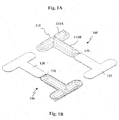
- FIGS. 1A and 1B show a transparent marker wrapper 100.
- Marker envelope 100 has a T-shaped configuration 110 formed by two cup-shaped longitudinal trenches 110A and 110B. The pass each other. The shape of the trenches becomes flatter towards the edge.
- a cover 120 is connected by a hinge 130.
- the lid is preferably flat and / or flat and closes the T-shaped opening formed by the two longitudinal trenches 110A and 110B.
- the longitudinal trenches 110A and 110B represent a depression, in particular a shell-like depression.
- the marker enclosure in particular all components such as cover 120, longitudinal trenches 110 and hinge 130, is preferably made of polypropylene, as used for example for pharmaceutical packaging.
- the film thickness is preferably less than 1 mm, in particular less than 500 ⁇ m, for example 300 ⁇ m.
- the marker wrapper is preferably formed from a film and formed by a deep drawing process.
- the marker coating and the raw materials used there correspond to the relevant BgVV, EC and FDA regulations for the production of pharmaceutical packaging.
- the physiological safety of the film is ensured.
- the film material is designed so that the crystal melting range according to ISO 3146 is above 100 ° C.
- the mechanical tensile strength according to ISO 527-3 is above 10 N / mm 2 .
- the surface gloss according to DIN 67530 is preferably> 70%, particularly preferably> 90%.
- Haze is ASTM D-1003 ⁇ 30%, more preferably ⁇ 20%.
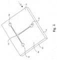
- a recess is preferably formed which comprises recesses 12a, 12b and 12c for marker spheres.
- the recesses are preferably cylindrically shaped to form corresponding cylinder-like indentation in the marker enclosure to allow easy insertion of the marker spheres.
- the recess 12 comprises a portion 12d, the at the forming of the marker envelope by the thermoforming mold to form a channel-shaped depression, which is provided for the introduction of the connecting arms of the reference star to the individual marker spheres.
- an entire reference star can thus be introduced into the depression corresponding to the recess 12 in the case of a marker envelope produced therewith.
- the marker envelope produced in this way can, like the embodiment according to FIG. 1, receive a reference star with a so-called T geometry.
- the markers need not be spherical, but can z. B. also flat, z. B. platelet-like or as a disc may be formed.
- the flat markers preferably have a rough surface with a plurality of reflective protrusions.
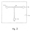
- Fig. 3 shows a plan view of the thermoforming mold of Fig. 2 The same parts are provided with the same reference numerals.
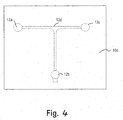
- Fig. 4 shows a view of the thermoforming mold from below, wherein like parts are provided with the same reference numerals.
- the underside of the cuboid has been designated by the reference numeral 10d.
- the recess 12 with the components 12a, 12b, 12c and 12d is shown in dashed lines, since, in contrast to FIG. 2 and FIG. 3, it does not open to the surface 10d.
- the recess 12 drawn throughout, since the surface 10 a is interrupted by the recess 12.
- thermoforming mold shown in FIGS. 2 to 5 is a negative mold.
Landscapes
- Health & Medical Sciences (AREA)
- Surgery (AREA)
- Life Sciences & Earth Sciences (AREA)
- Heart & Thoracic Surgery (AREA)
- Molecular Biology (AREA)
- Veterinary Medicine (AREA)
- Engineering & Computer Science (AREA)
- Biomedical Technology (AREA)
- Nuclear Medicine, Radiotherapy & Molecular Imaging (AREA)
- Medical Informatics (AREA)
- Public Health (AREA)
- Animal Behavior & Ethology (AREA)
- General Health & Medical Sciences (AREA)
- Pathology (AREA)
- Oral & Maxillofacial Surgery (AREA)
- Length Measuring Devices By Optical Means (AREA)
- Dental Tools And Instruments Or Auxiliary Dental Instruments (AREA)
- Medical Preparation Storing Or Oral Administration Devices (AREA)
Abstract

Description
- Die vorliegende Erfindung betrifft eine transparente Umhüllung für Marker, die für Trackingsysteme, insbesondere für medizinische Trackingsysteme (auch Navigationssysteme genannt) verwendet werden. Die Trackingsysteme dienen dazu, Positionen von Vorrichtungen zu bestimmen und zu verfolgen, indem die Position von Markern, die an der Vorrichtung angebracht sind, detektiert werden (z.B. mittels Kamera). Die medizinischen Trackingsysteme dienen insbesondere dazu, die Position eines Instruments oder eines Körperteils mit Hilfe von Markern und/oder eines daran angebrachten Referenzsterns zu bestimmen. Dieser Referenzstern weist die Marker auf. Die Marker sind entweder passive oder aktive Marker. Passive Marker reflektieren Licht, insbesondere Infrarotlicht (z.B. aber auch sichtbares oder UV-Licht), das auf sie gestrahlt wird. Aktive Marker senden von selbst Licht aus. Die Position der Marker, insbesondere des Referenzsterns und damit des Instruments oder Körperteils wird mit Hilfe von Kameras bestimmt, die das von den Markern ausgesandte Licht detektieren.
- Bei den Markern handelt es sich typischerweise um kugelförmige Marker, sie können aber auch eine andere Gestalt, wie z.B. würfelförmig, aufweisen. Insbesondere passive Marker sind an ihrer Oberfläche katzenaugenähnlich mit einer Vielzahl von kleinen Reflexionsflächen ausgebildet, die selbst wiederum kugelförmig oder halbkugelförmig sein können. Dadurch befinden sich eine Vielzahl von Vertiefungen auf den Markern, in denen sich Flüssigkeit , insbesondere Spülflüssigkeit, Blut oder Blutverschmierungen anlagern können. Dies kann die Abstrahlung von Licht von den Markern verändern. Dadurch kann das Navigationssystem die tatsächliche Position der Marker falsch berechnen. Insbesondere kann bei beispielsweise kugelförmigen Markern das Zentrum der Markerkugel falsch berechnet werden, falls das abgestrahlte Licht (aktives Licht oder reflektiertes Licht) durch die auf den Markern befindlichen Flecken oder Flüssigkeitstropfen geändert wird. Insbesondere kann es an der Oberfläche der Flüssigkeit zu zusätzlichen Reflexionen kommen, die die Abstrahlung beeinträchtigen.
- Problematisch ist bei der praktischen medizinischen Anwendung insbesondere, dass auf Grund der Vielzahl von Vertiefungen es schwer für den Praktiker (insbesondere Arzt oder Krankenschwester) erkennbar ist, ob sich Flüssigkeit oder Flecken auf dem Marker befinden. Somit weiß der Praktiker nicht, ob eine Reinigung der Marker notwendig ist. Insbesondere sorgen die Vertiefungen dafür, dass sich die Flüssigkeit auf der Oberfläche des Markers ausbreitet und schlechter zu sehen ist.
- Aufgabe der Erfindung ist es, eine Vorrichtung, ein System mit Markern und ein Trackingsystem zu schaffen, bei dem es leichter ist, eine Störung der optischen Abstrahlungseigenschaften der Marker zu erkennen und/oder bei dem zu beseitigen und/oder eine derartige Beeinträchtigung unwahrscheinlicher ist.
- Vorstehende Aufgabe wird durch die Gegenstände der unabhängigen Ansprüche 1, 9 und 10 gelöst. Die abhängigen Ansprüche sind auf vorteilhafte Ausführungsformen gerichtet.
- Erfindungsgemäß wird eine transparente Markerumhüllung bereitgestellt. Diese erlaubt es, die vorgenannten Probleme zu lösen. Vorzugsweise sind zumindest Abschnitte der Markerumhüllung, insbesondere die gesamte Markerumhüllung aus einem transparenten Material ausgebildet. Dieses transparente Material ist für diejenige (insbesondere optische) Strahlung transparent, die von Kameras des Navigationssystems detektiert wird, um die Position der Marker zu bestimmen. Die Strahlung geht von den Markern aus, weil sie von diesen reflektiert wird (passive Marken) oder von diesem abgestrahlt wird (aktive Marken). Insbesondere ist das Material für Infrarotstrahlung und/oder sichtbares Licht transparent.
- Transparent bedeutet hierbei insbesondere, dass ein Transmissionsgrad von 80% oder mehr, bevorzugt 90% oder mehr, besonders bevorzugt 95% oder mehr und höchst bevorzugt 99% oder mehr, für die zu detektierende Strahlung besteht. Insbesondere bedeutet transparent, dass der Reflexionsgrad für die zu detektierende Strahlung bevorzugt 20% oder weniger, besonders bevorzugt 10% oder weniger, noch mehr bevorzugt 5% oder weniger und höchst bevorzugt 1% oder weniger, beträgt. Insbesondere bedeutet transparent, dass der Absorptionsgrad für die zu detektierende Strahlung 20% oder weniger, bevorzugt 10% oder weniger, besonders bevorzugt 5% oder weniger und höchst bevorzugt 1% oder weniger beträgt.
- Bevorzugt weist die Markerumhüllung eine Oberfläche auf, die Flüssigkeit nicht aufnimmt, insbesondere nicht aufsaugt, insbesondere nicht durch Oberflächenspannungseffekte anzieht oder hält. Insbesondere ist die Markerumhüllung so ausgebildet, dass sie eine glatte, insbesondere zumindest abschnittsweise ebene Oberfläche aufweist. Bevorzugt ist die Oberfläche flüssigkeitsabweisend, insbesondere hydrophob ausgebildet. Insbesondere ist die Oberfläche und/oder das Material der Markerumhüllung aus einem Polymer, aus Polyvinylchlorid, aus Polyethylen, aus Polypropylen, aus Polycarbonat, oder aus Tetrafluorethylen oder einer Mischung aus dem vorgenannten ausgebildet. Die Oberfläche kann insbesondere silanisiert sein. Die Markerumhüllung kann auch so ausgebildet sein, dass sie im Infraroten transparent ist, aber im Sichtbaren nicht transparent ist. Insbesondere kann sie im Sichtbaren reflektierend sein und/oder weiß erscheinen, um so Verschmutzungen für den Praktiker leichter erkennen zu können, während vom Marker ausgestrahlte und detektierte Strahlen im Infraroten durch die Markerumhüllung hindurch gelangen.
- Vorzugsweise ist die Markerumhüllung in der Art eines Gehäuses ausgebildet, das einen Marker oder die Markeranordnung (Referenzstern) zumindest teilweise und vorzugsweise vollständig umgibt.
- Die Markerumhüllung kann auch in der Art einer Schutzschicht, die die Oberfläche des Markers glättet, den Marker teilweise umhüllen. Die Schutzschicht ist vorzugsweise direkt auf der Markeroberfläche aufgebracht.
- Die Markerumhüllung hat vorzugsweise eine stabile insbesondere starre Oberflächengestalt, um Verschmutzungen der Oberfläche leichter erkennen zu können und dies leichter abwischen zu können. Die Markerumhüllung nimmt vorzugsweise eine vorgeformte Gestalt ein. Sie ist insbesondere aus einem dünnen Material, insbesondere Kunststoffmaterial, ausgebildet. Dabei bedeutet "dünn" vorzugsweise weniger als 2 mm, insbesondere weniger als 1 mm, vorzugsweise weniger als 0,5 mm. Die Markerumhüllung kann Verstärkungen, Falze oder Falten aufweisen, um die Gestalt zu stabilisieren. Diese Verstärkungen, Falten oder Falze sind vorzugsweise so angeordnet, dass sie eine Detektion der Marker nicht stören.
- Vorzugsweise ist die Markerumhüllung mit einer vorgeformten Gestalt ausgebildet, die eine oder mehrere Vertiefungen aufweist, um einen oder mehrere Marker oder einen Referenzstern mit Marker oder z. B. eine Kombination aus zwei Markern (z. B. für einen Pointer) aufzunehmen. Ein Referenzstern umfasst insbesondere mindestens 2 oder 3 Marker, die durch mechanische Verbindungsglieder so verbunden sind, dass die Marker insbesondere eine Ebene (3 Marker) oder eine 3D-Gestalt (4 oder mehr Marker) aufspannen. Insbesondere ist die Vertiefung in der Gestalt so ausgebildet, dass die Marker bzw. der Referenzstern eingebettet wird. Dies bedeutet insbesondere, dass nach Einbringen des mindestens einen Markers oder des Referenzsterns in die Vertiefung der Markerumhüllung ein Deckel, insbesondere flacher Deckel die Vertiefung verschließen kann, um so den mindestens einen Marker durch Deckel und Vertiefung vollständig zu umschließen.
- Vorzugsweise ist die Markerumhüllung so gestaltet, dass mindestens ein Marker und/oder ein Referenzstern in die Markerumhüllung einbringbar ist, insbesondere auch wieder entnehmbar ist. Vorzugsweise weist die Markerumhüllung den vorgenannten Verschluss und/oder einen Deckel auf, der insbesondere ebenfalls transparent ist und vorzugsweise aus demselben Material ausgebildet ist. Der Verschluss ist vorzugsweise so gestaltet, dass der sich in der Ausnehmung befindliche mindestens eine Marker und/oder Referenzstern aus der Ausnehmung nur entnommen werden kann, wenn der Verschluss geöffnet wird. Vorzugsweise ist die Umhüllung so gestaltet, dass die Öffnung, die die Ausnehmung bildet, durch den Verschluss verschlossen wird. Der Verschluss ist besonders vorzugsweise so gestaltet, dass die Umhüllung abdichtend verschlossen wird, so dass keine Flüssigkeiten, insbesondere verschmutzende Flüssigkeiten in die Umhüllung eintreten können.
- Vorzugsweise weist die Markerumhüllung ein Mittel auf, um den mindestens einen Marker und/oder Referenzstern an einer vorgegebenen Position zu halten. Dazu kann eine Klemm- oder Presspassung und/oder ein Einschnappmechanismus vorgesehen werden, der den mindestens einen Marker und/oder Referenzstern hält, wenn dieser in die Markerumhüllung, insbesondere in die Ausnehmung eingebracht wird. Insbesondere kann auch der zuvor erwähnte Verschluss dazu ausgebildet sein, den mindestens einen Marker und/oder Referenzstern an der vorgesehenen Position zu halten.
- Vorzugsweise umfasst die Markerumhüllung einen Sensor, um Fremdstoffe zu erkennen oder nachzuweisen, die von den Markern ausgehende Strahlen beeinträchtigen können. Insbesondere ist der Sensor vorzugsweise so ausgebildet, dass er Flüssigkeiten oder Fremdstoffe an der Oberfläche der Markerumhüllung, insbesondere der Außenoberfläche der Markerumhüllung nachweisen oder detektieren kann. Der Sensor ist vorzugsweise so ausgebildet, dass er bei Nachweis eines Fremdstoffes oder einer Flüssigkeit ein detektierbares Signal, insbesondere ein optisches oder elektrisches Signal abgibt. Auf diese Art und Weise kann das Navigationssystem gewarnt werden, dass die von den Markern abgestrahlten Strahlen möglicherweise gestört oder beeinträchtigt sind. Auch kann der Sensor oder das Nachweismittel für Feuchtigkeit oder Fremdstoffe so ausgebildet sein, dass es sich für die Beobachtungskameras feststellbar optisch verändert. Dadurch wird eine zusätzliche Warnelektronik vermeidbar. Insbesondere kann die Oberfläche der Markerumhüllung so gestaltet sein, dass es sich bei Anfeuchtung verfärbt, so dass beispielsweise die Markerumhüllung schwarz und/oder für das zu detektierende Licht (z.B. IR-Licht) nicht mehr transparent wird, wenn sie mit Flüssigkeit in Kontakt kommt. Somit ist sichergestellt, dass keine fehlerhafte Navigation durchgeführt wird, da der Benutzer oder Praktiker sofort erkennt, dass die Abstrahlung von den Markern möglicherweise gestört ist. Er kann die Markerumhüllung wieder reinigen, um so die Störung zu beseitigen.
- Die transparente Markerumhüllung kann getrennt von den Markern oder Referenzsternen bereitgestellt werden. Die Marker oder Referenzsterne können aber auch in Kombination mit der Markerumhüllung angeboten werden. Insbesondere kann ein System aus Marker und Markerumhüllung auch so ausgebildet sein, dass die transparente Markerumhüllung fest um den mindestens einen Marker oder Referenzstern herum ausgebildet ist, insbesondere verschweißt ist oder der mindestens eine Marker und/oder Referenzstern in eine transparente Markerumhüllung eingegossen ist. Beispielsweise kann der mindestens eine Marker und/oder Referenzstern in eine transparente Kunststoffmasse eingegossen sein.
- Vorzugsweise wird ein Trackingsystem (auch Navigationssystem genannt) bereitgestellt, das einen Referenzstern und Kameras zur Detektion optischer Strahlung von den Markern des Referenzsterns umfasst, wobei mindestens einer der Marker und/oder der Referenzstern durch die erfindungsgemäße transparente Markerumhüllung umgeben sind. Im Falle passiver Marker ist vorzugsweise eine Marker-Beleuchtung vorgesehen, die Licht, insbesondere IR-Licht auf die Marker abstrahlt, das von diesen reflektiert wird. Vorzugsweise ist das Trackingsystem zum Navigieren eines medizinischen Instruments oder zum Feststellen einer Position eines Körperteils so ausgebildet, dass ein Warnsignal abgegeben wird, wenn ein Sensor Fremdstoffe oder Flüssigkeiten feststelle, die die Detektion der optischen Strahlung von den Markern beeinträchtigt, wie oben ausgeführt wurde. Das Trackingsystem kann aber auch in anderen Gebieten, wie z. B. Virtual Reality (z. B. Computer- oder Viedeospiele), Robotersteuerung, Sportmedizin usw. Anwendung finden.
- Im folgenden wird eine Ausführungsform der vorliegenden Erfindung erläutert. Dabei werden weitere Merkmale der Erfindung offenbart. Fig. 1A und 1B zeigen eine transparente Markerumhüllung gemäß einer Ausführungsform ab Erfindung;
- Fig. 2
- zeigt eine negative Tiefziehform für eine transparente Markerumhüllung gemäß einer weiteren Ausführungsform der Erfindung;
- Fig. 3
- zeigt eine Draufsicht auf die Ausführungsform der Fig. 1;
- Fig. 4
- zeigt eine Untenansicht auf die Ausführungsform der Fig. 1;
- Fig. 5
- zeigt eine Seitenansicht der Ausführungsform der Fig. 1.
- Fig. 1A und 1B zeigen eine transparente Markerumhüllung 100 . Die Markerumhüllung 100 weist eine T- förmige Gestalt 110, die durch zwei schalenförmige Längsgräben 110A und 110B gebildet wird. Die einander übergehen. Die Form der Gräben wird zum Rand hin flacher. Mit einem Längsgraben 110B ist an dem Ende, das dem Längsgraben 110A abgewandt ist ein Deckel 120 durch ein Schanier 130 verbunden. Der Deckel ist vorzugsweise flach und/oder eben ausgebildet und verschließt die durch die beiden Längsgräben 110A und 110B ausgebildete T-förmige Öffnung. Die Längsgräben 110A und 110B stellen eine Vertiefung, insbesondere schalenartige Vertiefung dar. Die Markerumhüllung, insbesondere sämtliche Bestandteile wie Deckel 120, Längsgräben 110 und Scharnier 130 ist vorzugsweise aus Polypropylen ausgebildet, wie es beispielsweise für pharmazeutische Verpackungen verwendet wird. Die Foliendicke ist vorzugsweise kleiner als 1 mm, insbesondere kleiner als 500 µm, beispielsweise 300 µm. Die Markerumhüllung wird vorzugsweise aus einer Folie gebildet und mittels eines Tiefziehverfahrens gebildet. Vorzugsweise entsprechen die Markerumhüllung und die dort eingesetzten Rohstoffe den einschlägigen BgVV-, EG- und FDA-Bestimmungen für die Herstellung von Pharmaverpackungen. Vorzugsweise ist die physiologische Unbedenklichkeit der Folie gewährleistet. Vorzugsweise ist das Folienmaterial so gestaltet, dass der Kristallschmelzbereich nach ISO 3146 bei über 100°C liegt. Vorzugsweise ist die mechanische Reißfestigkeit nach ISO 527-3 über 10 N/mm2. Vorzugsweise ist der Oberflächenglanz nach DIN 67530 >70%, besonders vorzugsweise >90%. Vorzugsweise ist die Trübung (Haze) nach ASTM D-1003 <30%, besonders vorzugsweise <20%.
- In der Tiefziehform gemäß Fig. 2 für eine transparente erfindungsgemäße Markerumhüllung ist vorzugsweise eine Ausnehmung ausgebildet, die Ausnehmungen 12a, 12b und 12c für Markerkugeln umfasst. Die Ausnehmungen sind vorzugsweise zylindrisch ausgebildet, um entsprechende zylinderähnliche Vertiefung in der Markerumhüllung auszubilden, um ein einfaches Einführen der Markerkugeln zu ermöglichen. Vorzugsweise umfasst die Ausnehmung 12 einen Abschnitt 12d, der bei der Formung der Markerumhüllung durch die Tiefziehform eine kanalförmige Vertiefung zu bilden, die für das Einbringen der Verbindungsarme des Referenzsterns zu den einzelnen Markerkugeln vorgesehen ist. Bei der in Fig. 1 gezeigten Ausführungsform kann somit bei einer damit hergestellten Markerumhüllung ein gesamter Referenzstern in die der Ausnehmung 12 entsprechende Vertiefung eingebracht werden. Die so hergestellte Markerumhüllung kann ebenso wie die Ausführungsform gemäß Fig. 1 einen Referenzstern mit einer so genannten T-Geometrie aufnehmen.
- Die Marker müssen nicht kugelförmig sein, sondern können z. B. auch flach, z. B. plättchen-ähnlich oder wie eine Scheibe ausgebildet sein. Die flachen Marker weisen vorzugsweise eine rauhe Oberfläche mit einer Vielzahl von reflektierenden Erhebungen auf.
- Anwendungen der Erfindung liegen insbesondere bei Kniegelenkkreuzband-Operationen (ACL-Operationen), bei Tracking- oder Navigationsanwendungen wie den so genannten Vector Vision Spine, also einer Navigationsanwendung auf dem Gebiet der Wirbelsäule und dem so genannten Vector Vision Trauma (VV-Trauma) und der Radiotherapie. Andere medizinische und nicht-medizinische Anwendungen betreffen jegliche Art der Bewegungsanalyse und Bewegungserfassung von Körpern und Vorrichtungen. Beispiele sind Viedeospiele, Fernseh- und Filmanimationen, Virtual Reality, Ganganalyse (insbesondere beim Menschen oder Tier), Körperbewegungsanalyse (Sportmedizin), Analyse von Prothesen, Neurowissenschaften, Produkt-Design, usw.
Fig. 3 zeigt eine Draufsicht der Tiefziehform der Fig. 2 Gleiche Teile sind mit gleichen Bezugszeichen versehen. - Fig. 4 zeigt eine Ansicht der Tiefziehform von unten, wobei gleiche Teile mit gleichen Bezugszeichen versehen sind. Die Unterseite des Quaders wurde mit dem Bezugszeichen 10d bezeichnet. Die Ausnehmung 12 mit den Bestandteilen 12a, 12b, 12c und 12d ist gestrichelt gezeichnet, da wobei sie sich im Gegensatz zu Fig. 2 und Fig. 3 nicht zur Oberfläche 10d hin öffnet. In Fig. 2 und Fig. 3 ist die Ausnehmung 12 durchgehend gezeichnet, da die Oberfläche 10a durch die Ausnehmung 12 unterbrochen ist.
- Fig. 5 zeigt eine Seitenansicht der Tiefziehform der Fig. 2 . Gleiche Teile sind wiederum mit gleichen Bezugszeichen versehen. Die Ausnehmung 12 mit den Bestandteilen 12a, 12b, 12c und 12d ist wiederum strichliert, da sie sich nicht zur Seitenfläche 10c öffnen Die in Figur 2 bis 5 gezeigte Tiefziehform ist eine Negativform.
Claims (12)
- Transparente Markerumhüllung (100) für medizinische Zwecke, wobei die Markerumhüllung ein Material aufweist, das für von mindestens einem Marker ausgehende Strahlen transparent ist, und wobei die Markerumhüllung so ausgebildet ist, dass sie den mindestens einen Marker mindestens teilweise umgibt.
- Transparente Markerumhüllung (100) nach Anspruch 1, wobei das Material eine Flüssigkeit nicht aufnehmende, insbesondere glatte und/oder flüssigkeitsabweisende Oberfläche aufweist.
- Transparente Markerumhüllung (100) nach einem der vorhergehenden Ansprüche, wobei die Markerumhüllung eine vorgeformte, stabile Gestalt (110, 120) aus insbesondere dünnem Kunststoffmaterial aufweist.
- Transparente Markerumhüllung (100) nach einem der vorhergehenden Ansprüche, wobei die Markerumhüllung ausgebildet ist, einen Referenzstern mit Markern zumindest teilweise zu umgeben.
- Transparente Markerumhüllung (100) nach einem der vorhergehenden Ansprüche, wobei die Umhüllung eine Vertiefung (110A, 110B) aufweist, in der mindestens ein Marker aufgenommen werden kann, um ihn mit der Umhüllung zumindest teilweise zu umgeben.
- Transparente Markerumhüllung (100) nach einem der vorhergehenden Ansprüche, wobei die Umhüllung verschließbar ist und durch Öffnen des Verschlusses (110)der mindestens eine Marker und/oder der Referenzstern einbringbar oder entnehmbar ist.
- Transparente Markerumhüllung (100) nach einem der vorhergehenden Ansprüche, wobei die Umhüllung (100) so ausgebildet ist, dass, wenn der mindestens eine Marker an einer für ihn vorgesehenen Position innerhalb der Umhüllung (100) ist, der mindestens eine Marker verlagerungsfest relativ zur Umhüllung ist.
- Transparente Markerumhüllung (100) nach einem der vorhergehenden Ansprüche, wobei die Umhüllung (100) einen Feuchtigkeitssensor aufweist, der Feuchtigkeit oder Flüssigkeit auf der Außenseite der Umhüllung feststellen kann und darauf basierend ein Signal abgibt oder sich für Beobachtungskameras bei Kontakt mit Feuchtigkeit oder Flüssigkeit feststellbar optisch verändert.
- System aus mindestens einem Marker für medizinische Navigationszwecke und der transparenten Markerumhüllung nach einem der Ansprüche 1 bis 10.
- Trackingsystem mit einer transparenten Markerumhüllung nach einem der Ansprüche 1 bis 8 und mit mindestens einem Marker und Kameras zur Detektion von optischer Strahlung von den Markern, wobei der mindestens einen Marker von der Markerumhüllung umgeben ist.
- Trackingsystem nach Anspruch 10, wobei die Markerumhüllung gemäß Anspruch 8 ausgebildet ist und das Trackingsystem ein Warnsignal abgibt und/oder der mindestens eine umhüllte Marker nicht mehr detektierbar ist, wenn der Sensor Feuchtigkeit oder Flüssigkeit feststellt oder damit in Kontakt kommt.
- Verwendung der transparenten Markerumhüllung nach einem der Ansprüche 1 bis 8 oder des Systems nach Anspruch 9 oder des Trackingsystems nach Anspruch 10 oder 11 auf dem Gebiet der Bewegungsanalyse und/oder Bewegungsverfolgung von Geräten und/oder Körpern urid/oder Teilen davon.
Priority Applications (3)
| Application Number | Priority Date | Filing Date | Title |
|---|---|---|---|
| EP04027430A EP1658819B1 (de) | 2004-11-18 | 2004-11-18 | Transparente Markerumhüllung |
| DE502004005849T DE502004005849D1 (de) | 2004-11-18 | 2004-11-18 | Transparente Markerumhüllung |
| US11/283,501 US7820446B2 (en) | 2004-11-18 | 2005-11-18 | System for tracking a spatial position of an object via a tracking system |
Applications Claiming Priority (1)
| Application Number | Priority Date | Filing Date | Title |
|---|---|---|---|
| EP04027430A EP1658819B1 (de) | 2004-11-18 | 2004-11-18 | Transparente Markerumhüllung |
Publications (2)
| Publication Number | Publication Date |
|---|---|
| EP1658819A1 true EP1658819A1 (de) | 2006-05-24 |
| EP1658819B1 EP1658819B1 (de) | 2008-01-02 |
Family
ID=34927446
Family Applications (1)
| Application Number | Title | Priority Date | Filing Date |
|---|---|---|---|
| EP04027430A Expired - Lifetime EP1658819B1 (de) | 2004-11-18 | 2004-11-18 | Transparente Markerumhüllung |
Country Status (3)
| Country | Link |
|---|---|
| US (1) | US7820446B2 (de) |
| EP (1) | EP1658819B1 (de) |
| DE (1) | DE502004005849D1 (de) |
Cited By (1)
| Publication number | Priority date | Publication date | Assignee | Title |
|---|---|---|---|---|
| WO2009135838A1 (de) * | 2008-05-06 | 2009-11-12 | Bernhard Hauri | Marker für ein navigationssystem |
Families Citing this family (23)
| Publication number | Priority date | Publication date | Assignee | Title |
|---|---|---|---|---|
| US20090088686A1 (en) * | 2007-09-27 | 2009-04-02 | Cook Harold D | Method of locating vessel puncture access sites via tattoo or permanent marking |
| US8364243B2 (en) * | 2008-04-30 | 2013-01-29 | Nanosys, Inc. | Non-fouling surfaces for reflective spheres |
| WO2010055193A1 (en) * | 2008-11-14 | 2010-05-20 | Nexstim Oy | Trackers for optical navigation of image-guided tools |
| US20110202003A1 (en) * | 2010-02-18 | 2011-08-18 | Cook Harold D | Method of locating vessel puncture access sites via tattoo or permanent marking |
| US8668345B2 (en) | 2011-11-30 | 2014-03-11 | Izi Medical Products | Retro-reflective marker with snap on threaded post |
| US8661573B2 (en) | 2012-02-29 | 2014-03-04 | Izi Medical Products | Protective cover for medical device having adhesive mechanism |
| US9713498B2 (en) | 2013-03-15 | 2017-07-25 | Stryker Corporation | Assembly for positioning a sterile surgical drape relative to optical position sensors |
| US10842582B2 (en) | 2016-02-26 | 2020-11-24 | Brainlab Ag | Sterile surgical drape with inherently stable tracking reference array cover |
| US10154885B1 (en) | 2017-05-26 | 2018-12-18 | Medline Industries, Inc. | Systems, apparatus and methods for continuously tracking medical items throughout a procedure |
| US11096754B2 (en) | 2017-10-04 | 2021-08-24 | Mako Surgical Corp. | Sterile drape assembly for surgical robot |
| EP3643268B1 (de) | 2018-10-23 | 2026-03-18 | DePuy Ireland Unlimited Company | Chirurgische navigationsreferenz mit spritzschutz |
| US11617625B2 (en) | 2019-03-12 | 2023-04-04 | Medline Industries, Lp | Systems, apparatus and methods for properly locating items |
| US11690680B2 (en) | 2019-03-19 | 2023-07-04 | Mako Surgical Corp. | Trackable protective packaging for tools and methods for calibrating tool installation using the same |
| US11832892B2 (en) | 2019-07-10 | 2023-12-05 | Mako Surgical Corp. | Navigation systems for communicating tracker status conditions |
| US12059276B2 (en) | 2019-08-21 | 2024-08-13 | Medline Industries, Lp | Systems, apparatus and methods for automatically counting medical objects, estimating blood loss and/or communicating between medical equipment |
| WO2022150284A1 (en) | 2021-01-06 | 2022-07-14 | Mako Surgical Corp. | Tracker for a navigation system |
| CN113288355A (zh) * | 2021-05-17 | 2021-08-24 | 苏州心速度医疗技术有限公司 | 穿刺辅助引导装置 |
| AU2023228586A1 (en) | 2022-03-02 | 2024-09-12 | Mako Surgical Corp. | Robotic system including a link tracker |
| DE102023109398A1 (de) | 2023-04-14 | 2024-10-17 | Soft2Tec Gmbh | Verfahren zur Herstellung einer formstabilen Schutzabdeckung für eine Markiervorrichtung und Markiervorrichtung mit Schutzabdeckung |
| USD1139999S1 (en) | 2023-08-18 | 2026-08-04 | Stryker European Operations Limited | Surgical instrument |
| USD1121826S1 (en) | 2023-08-18 | 2026-04-07 | Stryker European Operations Limited | Surgical tracker |
| USD1117755S1 (en) | 2023-08-18 | 2026-03-10 | Mako Surgical Corp. | Surgical tracker |
| USD1120320S1 (en) | 2023-08-18 | 2026-03-24 | Mako Surgical Corp. | Surgical tracker |
Citations (4)
| Publication number | Priority date | Publication date | Assignee | Title |
|---|---|---|---|---|
| EP0566861A1 (de) * | 1992-04-23 | 1993-10-27 | Olympus Optical Co., Ltd. | Endoskopgerät |
| US5588430A (en) * | 1995-02-14 | 1996-12-31 | University Of Florida Research Foundation, Inc. | Repeat fixation for frameless stereotactic procedure |
| WO1999004719A1 (de) * | 1997-07-24 | 1999-02-04 | Karl Storz Gmbh & Co. | Endoskopisches instrument zur durchführung von endoskopischen eingriffen oder untersuchungen und endoskopisches instrumentarium, enthaltend ein solches endoskopisches instrument |
| WO1999040869A1 (en) * | 1998-02-17 | 1999-08-19 | The University Of Iowa Research Foundation | Lesion localizer for nuclear medicine |
Family Cites Families (6)
| Publication number | Priority date | Publication date | Assignee | Title |
|---|---|---|---|---|
| US4178735A (en) | 1977-07-13 | 1979-12-18 | The Kendall Company | Method of sheathing catheter |
| US4349031A (en) | 1980-03-07 | 1982-09-14 | The Kendall Company | Esophageal probe with disposable cover |
| US5224373A (en) * | 1991-05-09 | 1993-07-06 | Williams Christi A | Flexible humidity indicator and container |
| US5237984A (en) | 1991-06-24 | 1993-08-24 | Xomed-Treace Inc. | Sheath for endoscope |
| US5524643A (en) * | 1995-05-02 | 1996-06-11 | O.R. Solutions, Inc. | Method and apparatus for detection of liquid and leaks in surgical drapes used with surgical equipment |
| US5816252A (en) * | 1997-04-29 | 1998-10-06 | O.R. Solutions, Inc. | Surgical drape leak detection method and apparatus |
-
2004
- 2004-11-18 EP EP04027430A patent/EP1658819B1/de not_active Expired - Lifetime
- 2004-11-18 DE DE502004005849T patent/DE502004005849D1/de not_active Expired - Lifetime
-
2005
- 2005-11-18 US US11/283,501 patent/US7820446B2/en not_active Expired - Fee Related
Patent Citations (4)
| Publication number | Priority date | Publication date | Assignee | Title |
|---|---|---|---|---|
| EP0566861A1 (de) * | 1992-04-23 | 1993-10-27 | Olympus Optical Co., Ltd. | Endoskopgerät |
| US5588430A (en) * | 1995-02-14 | 1996-12-31 | University Of Florida Research Foundation, Inc. | Repeat fixation for frameless stereotactic procedure |
| WO1999004719A1 (de) * | 1997-07-24 | 1999-02-04 | Karl Storz Gmbh & Co. | Endoskopisches instrument zur durchführung von endoskopischen eingriffen oder untersuchungen und endoskopisches instrumentarium, enthaltend ein solches endoskopisches instrument |
| WO1999040869A1 (en) * | 1998-02-17 | 1999-08-19 | The University Of Iowa Research Foundation | Lesion localizer for nuclear medicine |
Cited By (2)
| Publication number | Priority date | Publication date | Assignee | Title |
|---|---|---|---|---|
| WO2009135838A1 (de) * | 2008-05-06 | 2009-11-12 | Bernhard Hauri | Marker für ein navigationssystem |
| US8534848B2 (en) | 2008-05-06 | 2013-09-17 | Bernhard Hauri | Marker for a navigation system |
Also Published As
| Publication number | Publication date |
|---|---|
| DE502004005849D1 (de) | 2008-02-14 |
| US20060140464A1 (en) | 2006-06-29 |
| US7820446B2 (en) | 2010-10-26 |
| EP1658819B1 (de) | 2008-01-02 |
Similar Documents
| Publication | Publication Date | Title |
|---|---|---|
| EP1658819B1 (de) | Transparente Markerumhüllung | |
| DE69306659T2 (de) | Packung für eine aktive medizinische Vorrichtung | |
| DE102018206406B3 (de) | Mikroskopiesystem und Verfahren zum Betrieb eines Mikroskopiesystems | |
| DE69007161T2 (de) | Kalibrierungskappe für in-vitro-Eichung eines Sauerstoffsättigungsanzeigers und dessen Anwendungsverfahren. | |
| US5584823A (en) | Illuminated eye dropper device | |
| DE69729459T2 (de) | Tragbare bildaufnahmeeinheit für das auge | |
| EP1645241A1 (de) | Positionsmarkersystem mit Punktlichtquellen | |
| EP2309943B1 (de) | Marker für ein navigationssystem | |
| EP0360063B1 (de) | Aufbewahrungs- und Untersuchungsvorrichtung für Kontaktlinsen | |
| EP1297511B1 (de) | Verfahren und vorrichtung zur überwachung des innenraums und des umfeldes eines fahrzeugs | |
| EP0722691A1 (de) | System zur Bestimmung von Gewebeeigenschaften | |
| EP1453416B1 (de) | Ophthalmische einweglinse | |
| WO2000059366A3 (en) | Identification of protective covers for medical imaging devices | |
| Desanghere et al. | The influence of object shape and center of mass on grasp and gaze | |
| WO2018229225A1 (de) | Fenstersystem für einen intraoralscanner | |
| DE102007007742B4 (de) | Medizinischer oder chirurgischer Sterilüberzug | |
| WO2018077731A1 (de) | Sterile abdeckung für ein optisches gerät | |
| WO2013167274A1 (de) | Aufsatz für ein kontaktglas sowie herstellungsverfahren für ein kontaktglassystem | |
| DE3800076C2 (de) | ||
| CH676754A5 (de) | ||
| DE102007043997A1 (de) | Schutzglas-Modul zur Adaption an das Hauptobjektiv eines Operationsmikroskops | |
| DE10341161B3 (de) | Testvorrichtung für Intraokularlinsen | |
| McCarville et al. | The visual control of stepping operates in real time: evidence from a pictorial illusion | |
| EP1645228B1 (de) | Trackingsystem mit Streueffekt-Nutzung | |
| DE102004052403A1 (de) | Verfahren zum Messen einer biologischen Probe mit hoher Genauigkeit |
Legal Events
| Date | Code | Title | Description |
|---|---|---|---|
| PUAI | Public reference made under article 153(3) epc to a published international application that has entered the european phase |
Free format text: ORIGINAL CODE: 0009012 |
|
| 17P | Request for examination filed |
Effective date: 20041118 |
|
| AK | Designated contracting states |
Kind code of ref document: A1 Designated state(s): AT BE BG CH CY CZ DE DK EE ES FI FR GB GR HU IE IS IT LI LU MC NL PL PT RO SE SI SK TR |
|
| AX | Request for extension of the european patent |
Extension state: AL HR LT LV MK YU |
|
| 17Q | First examination report despatched |
Effective date: 20051116 |
|
| AKX | Designation fees paid |
Designated state(s): DE FR GB IT |
|
| GRAP | Despatch of communication of intention to grant a patent |
Free format text: ORIGINAL CODE: EPIDOSNIGR1 |
|
| GRAS | Grant fee paid |
Free format text: ORIGINAL CODE: EPIDOSNIGR3 |
|
| GRAA | (expected) grant |
Free format text: ORIGINAL CODE: 0009210 |
|
| AK | Designated contracting states |
Kind code of ref document: B1 Designated state(s): DE FR GB IT |
|
| REG | Reference to a national code |
Ref country code: GB Ref legal event code: FG4D Free format text: NOT ENGLISH |
|
| REF | Corresponds to: |
Ref document number: 502004005849 Country of ref document: DE Date of ref document: 20080214 Kind code of ref document: P |
|
| GBT | Gb: translation of ep patent filed (gb section 77(6)(a)/1977) |
Effective date: 20080130 |
|
| ET | Fr: translation filed | ||
| PLBE | No opposition filed within time limit |
Free format text: ORIGINAL CODE: 0009261 |
|
| STAA | Information on the status of an ep patent application or granted ep patent |
Free format text: STATUS: NO OPPOSITION FILED WITHIN TIME LIMIT |
|
| 26N | No opposition filed |
Effective date: 20081003 |
|
| GBPC | Gb: european patent ceased through non-payment of renewal fee |
Effective date: 20081118 |
|
| PG25 | Lapsed in a contracting state [announced via postgrant information from national office to epo] |
Ref country code: IT Free format text: LAPSE BECAUSE OF FAILURE TO SUBMIT A TRANSLATION OF THE DESCRIPTION OR TO PAY THE FEE WITHIN THE PRESCRIBED TIME-LIMIT Effective date: 20080102 |
|
| PG25 | Lapsed in a contracting state [announced via postgrant information from national office to epo] |
Ref country code: GB Free format text: LAPSE BECAUSE OF NON-PAYMENT OF DUE FEES Effective date: 20081118 |
|
| REG | Reference to a national code |
Ref country code: DE Ref legal event code: R082 Ref document number: 502004005849 Country of ref document: DE Representative=s name: SCHWABE SANDMAIR MARX, DE |
|
| REG | Reference to a national code |
Ref country code: DE Ref legal event code: R082 Ref document number: 502004005849 Country of ref document: DE Representative=s name: SCHWABE SANDMAIR MARX, DE Effective date: 20131104 Ref country code: DE Ref legal event code: R081 Ref document number: 502004005849 Country of ref document: DE Owner name: BRAINLAB AG, DE Free format text: FORMER OWNER: BRAINLAB AG, 85622 FELDKIRCHEN, DE Effective date: 20131104 Ref country code: DE Ref legal event code: R082 Ref document number: 502004005849 Country of ref document: DE Representative=s name: SCHWABE SANDMAIR MARX PATENTANWAELTE RECHTSANW, DE Effective date: 20131104 |
|
| REG | Reference to a national code |
Ref country code: FR Ref legal event code: CA Effective date: 20131122 Ref country code: FR Ref legal event code: CD Owner name: BRAINLAB AG Effective date: 20131122 |
|
| REG | Reference to a national code |
Ref country code: FR Ref legal event code: PLFP Year of fee payment: 12 |
|
| REG | Reference to a national code |
Ref country code: FR Ref legal event code: PLFP Year of fee payment: 13 |
|
| PGFP | Annual fee paid to national office [announced via postgrant information from national office to epo] |
Ref country code: DE Payment date: 20161121 Year of fee payment: 13 Ref country code: FR Payment date: 20161118 Year of fee payment: 13 |
|
| REG | Reference to a national code |
Ref country code: DE Ref legal event code: R082 Ref document number: 502004005849 Country of ref document: DE Representative=s name: SCHWABE SANDMAIR MARX PATENTANWAELTE RECHTSANW, DE Ref country code: DE Ref legal event code: R081 Ref document number: 502004005849 Country of ref document: DE Owner name: BRAINLAB AG, DE Free format text: FORMER OWNER: BRAINLAB AG, 85622 FELDKIRCHEN, DE |
|
| REG | Reference to a national code |
Ref country code: FR Ref legal event code: CA Effective date: 20170706 |
|
| REG | Reference to a national code |
Ref country code: DE Ref legal event code: R119 Ref document number: 502004005849 Country of ref document: DE |
|
| REG | Reference to a national code |
Ref country code: FR Ref legal event code: ST Effective date: 20180731 |
|
| PG25 | Lapsed in a contracting state [announced via postgrant information from national office to epo] |
Ref country code: FR Free format text: LAPSE BECAUSE OF NON-PAYMENT OF DUE FEES Effective date: 20171130 Ref country code: DE Free format text: LAPSE BECAUSE OF NON-PAYMENT OF DUE FEES Effective date: 20180602 |