EP1658753B1 - Loudspeaker having a composite diaphragm structure - Google Patents
Loudspeaker having a composite diaphragm structure Download PDFInfo
- Publication number
- EP1658753B1 EP1658753B1 EP04744755A EP04744755A EP1658753B1 EP 1658753 B1 EP1658753 B1 EP 1658753B1 EP 04744755 A EP04744755 A EP 04744755A EP 04744755 A EP04744755 A EP 04744755A EP 1658753 B1 EP1658753 B1 EP 1658753B1
- Authority
- EP
- European Patent Office
- Prior art keywords
- shaped diaphragm
- cone
- diaphragm
- dome
- loudspeaker
- Prior art date
- Legal status (The legal status is an assumption and is not a legal conclusion. Google has not performed a legal analysis and makes no representation as to the accuracy of the status listed.)
- Not-in-force
Links
Images

Classifications
-
- H—ELECTRICITY
- H04—ELECTRIC COMMUNICATION TECHNIQUE
- H04R—LOUDSPEAKERS, MICROPHONES, GRAMOPHONE PICK-UPS OR LIKE ACOUSTIC ELECTROMECHANICAL TRANSDUCERS; DEAF-AID SETS; PUBLIC ADDRESS SYSTEMS
- H04R7/00—Diaphragms for electromechanical transducers; Cones
- H04R7/02—Diaphragms for electromechanical transducers; Cones characterised by the construction
- H04R7/12—Non-planar diaphragms or cones
- H04R7/122—Non-planar diaphragms or cones comprising a plurality of sections or layers
-
- H—ELECTRICITY
- H04—ELECTRIC COMMUNICATION TECHNIQUE
- H04R—LOUDSPEAKERS, MICROPHONES, GRAMOPHONE PICK-UPS OR LIKE ACOUSTIC ELECTROMECHANICAL TRANSDUCERS; DEAF-AID SETS; PUBLIC ADDRESS SYSTEMS
- H04R7/00—Diaphragms for electromechanical transducers; Cones
- H04R7/16—Mounting or tensioning of diaphragms or cones
- H04R7/18—Mounting or tensioning of diaphragms or cones at the periphery
- H04R7/20—Securing diaphragm or cone resiliently to support by flexible material, springs, cords, or strands
-
- H—ELECTRICITY
- H04—ELECTRIC COMMUNICATION TECHNIQUE
- H04R—LOUDSPEAKERS, MICROPHONES, GRAMOPHONE PICK-UPS OR LIKE ACOUSTIC ELECTROMECHANICAL TRANSDUCERS; DEAF-AID SETS; PUBLIC ADDRESS SYSTEMS
- H04R9/00—Transducers of moving-coil, moving-strip, or moving-wire type
- H04R9/02—Details
-
- H—ELECTRICITY
- H04—ELECTRIC COMMUNICATION TECHNIQUE
- H04R—LOUDSPEAKERS, MICROPHONES, GRAMOPHONE PICK-UPS OR LIKE ACOUSTIC ELECTROMECHANICAL TRANSDUCERS; DEAF-AID SETS; PUBLIC ADDRESS SYSTEMS
- H04R31/00—Apparatus or processes specially adapted for the manufacture of transducers or diaphragms therefor
- H04R31/003—Apparatus or processes specially adapted for the manufacture of transducers or diaphragms therefor for diaphragms or their outer suspension
-
- H—ELECTRICITY
- H04—ELECTRIC COMMUNICATION TECHNIQUE
- H04R—LOUDSPEAKERS, MICROPHONES, GRAMOPHONE PICK-UPS OR LIKE ACOUSTIC ELECTROMECHANICAL TRANSDUCERS; DEAF-AID SETS; PUBLIC ADDRESS SYSTEMS
- H04R7/00—Diaphragms for electromechanical transducers; Cones
- H04R7/02—Diaphragms for electromechanical transducers; Cones characterised by the construction
- H04R7/12—Non-planar diaphragms or cones
- H04R7/127—Non-planar diaphragms or cones dome-shaped
-
- H—ELECTRICITY
- H04—ELECTRIC COMMUNICATION TECHNIQUE
- H04R—LOUDSPEAKERS, MICROPHONES, GRAMOPHONE PICK-UPS OR LIKE ACOUSTIC ELECTROMECHANICAL TRANSDUCERS; DEAF-AID SETS; PUBLIC ADDRESS SYSTEMS
- H04R9/00—Transducers of moving-coil, moving-strip, or moving-wire type
- H04R9/06—Loudspeakers
Definitions
- the invention relates to a loudspeaker provided with a chassis, a movable body, a resilient suspension for guiding the movable body with respect to the chassis along a translation axis, and an electric actuator for driving the movable body along the translation axis.
- Speakers of such a type are generally known; e.g. PCT Patent WO 96/14722 discloses such a loudspeaker.
- This known loudspeaker has a frame, a membrane and an electromagnetic driving unit
- the membrane is formed by a conical body and has an outer circumferential edge and an inner circumferential edge.
- the driving unit is provided with a stationary part and a movable part.
- the stationary part includes a permanent magnet and a magnetic yoke and is secured to the frame.
- the movable part includes a voice coil and a cylindrical coil support. At its outer circumferential edge, the membrane is connected to the frame by means of a flexible suspension and, at its inner circumferential edge, it is adhered to the coil support, which in its turn is connected to the frame by means of a spider.
- the conical membrane of the known loudspeaker has a certain height in order to obtain sufficient stiffness.
- the membrane must have a certain minimal stiffness in order to be able to move like a piston, not only for low frequency reproduction but for the whole or at least the larger part of the audio spectrum.
- JP62150997 discloses a loudspeaker in which a voice coil is connected with a dome diaphragm in the vicinity of a node of vibration of the dome diaphragm.
- the outer periphery of the dome diaphragm is connected to a cone diaphragm in the vicinity of a node of vibration of the cone diaphragm.
- the loudspeaker according to the invention has a diaphragm structure which is composed of an outwardly convex, particularly dome-shaped, diaphragm and a cone-shaped diaphragm situated around the other diaphragm.
- a diaphragm structure which is composed of an outwardly convex, particularly dome-shaped, diaphragm and a cone-shaped diaphragm situated around the other diaphragm.
- a cone-shaped diaphragm known per se may be used.
- a rigid dome-shaped diaphragm known per se may be used.
- Such diaphragms are known, for instance, from US-A 3,925,626 .
- the loudspeaker according to the invention can be driven by a usual audio transformer of an amplifier system known per se.
- a favorable embodiment of the loudspeaker according to the invention has the characteristic feature that the electric actuator comprises a stationary part which is secured to the chassis or to a stationary element fixed to the chassis and further comprises a translatable part which is secured to the dome-shaped diaphragm. Due to this feature; the translatable part of the electric actuator extends into the space enveloped by the dome-shaped diaphragm.
- said US-A 3,925,626 discloses an all-frequency loudspeaker which has a domed diaphragm instead of the usual cone diaphragm of the prior art in order to get, inter alia, a high-fidelity sound.
- a form Secured to the underside of the diaphragm is a form which extends downwards into an air gap formed by a pole piece and atopring of a magnet system and on which a voice coil has been wound.
- the device formed by the diaphragm and the form is suspended from a framework by means of a resilient suspension secured to both the diaphragm and the framework and a resilient support secured to both the form and the framework.
- a disadvantage of this known loudspeaker is its height, which has to be substantial in order to provide sufficient distance between the lower resilient support and the topring to realize the required travel of the diaphragm. Contrary to the known devices, the loudspeaker according to the invention has no suspension means secured to the coil support, and thus does not have the above-described disadvantage.
- the back portion of the cone-shaped diaphragm includes an inner circumferential edge to which an outer circumferential rim of the dome-shaped diaphragm is connected, said edge and rim being preferably attached to each other by means of an adhesive, such as a glue.
- an adhesive such as a glue.
- the stationary part includes a magnetic yoke with a permanent magnet and the translatable part includes a coil support with a voice coil, which coil extends in an air gap of the magnetic yoke and has a coil axis coinciding with the translation axis of the movable body.
- the loudspeaker according to the invention is suitable for sound reproduction in hifi, home, automotive, TV and multimedia systems and, as already indicated, is particularly suitable for applications having very small built-in depths.
- the invention also relates to a diaphragm structure intended for use in the loudspeaker according to the invention.
- the diaphragm structure according to the invention has the characterising feature that it is composed of a central dome-shaped diaphragm and a cone-shaped diaphragm concentrically arranged with respect to the dome-shaped diaphragm.
- the diaphragm structure according to the invention has the characterising feature that it is composed of a central dome-shaped diaphragm and a cone-shaped diaphragm concentrically arranged with respect to the dome-shaped diaphragm.
- the invention further relates to a loudspeaker unit comprising the loudspeaker according to the invention and also comprising a housing accommodating the loudspeaker.
- the electrodynamic loudspeaker shown in the Figures, comprises a chassis 2, a movable body 4 and an electromagnetic actuator 6.
- the loudspeaker may be accommodated in a housing.
- the chassis 2 may be fixed in an appropriate opening in a wall of this housing.
- the housing is shown diagrammatically by means of a wall section 1 in broken lines.
- the movable body 4 has a three-dimensional diaphragm structure comprising a central dome-shaped diaphragm 8 and a cone-shaped diaphragm 10 concentrically arranged with respect to the dome-shaped diaphragm 8.
- the dome-shaped diaphragm 8 may be made of a metal, such as aluminium; reinforced plastics; pressed paper; or any other suitable material.
- the diaphragm 8 has a sufficient stiffness and may be provided with a central opening 8a covered by a dust cap 9 of any suitable material, such as paper, plastics, or textile.
- the cone-shaped diaphragm 10 may be made of pressed paper, carbon fiber, polyglass, aluminium, or any other suitable material.
- the cone-shaped diaphragm 10 has a back portion 10 b and a front portion 10 f which is wider than the back portion 10 b .
- the dome-shaped diaphragm 8 and the cone-shaped diaphragm 10 are mutually secured at the back portion 10 b .
- the cone-shaped diaphragm 10 has an inner circumferential edge 10 i
- the dome-shaped diaphragm 8 has a corresponding outer circumferential rim 8 o .
- the edge 10i and the rim 8 o preferably have round cross-sections so that the edge 10 i and the rim 8 o fit each other.
- the edge 10 i and the rim 8 o are preferably glued to each other.
- the loudspeaker further comprises a resilient suspension for suspending the movable body 4 from the chassis 2 and for guiding the movable body along a translation axis T.
- the suspension includes a first resilient element 12a and a second resilient element 12b.
- the first resilient element 12a is a ring-like spider, an inner circumferential brim 12a; of which is attached to the edge 10 i and/or the rim 8 o and an outer circumferential brim 12a o is attached to the chassis 2.
- a glue may be used for both attachments.
- the spider 12a may be a known flexible corrugated body and ensures that the movable body 4 can perform well-defined translation movements with respect to the chassis 2.
- the second resilient element 12b has a roll structure known per se and is formed, for example, from a bent rubber or foam annular strip. On its outer circumference, the second element 12b is secured, for example glued, to the chassis 2 and on its inner circumference to an outer circumferential edge 10 o of the cone-shaped membrane 10.
- the actuator 6 essentially comprises two elements, namely a stationary actuator part 6a which is fixed to the chassis 2 and a translatable actuator part 6b which is connected to the movable body 4 .
- One of the actuator parts - in this example the part 6a - is provided with a permanent magnet 13, in this example annular in shape and axially polarized, and the other actuator part - in this example the part 6b - is provided with a magnet coil 14.
- the permanent magnet 13 is formed from a neodymium-iron-boron alloy and forms a magnetic yoke 13a with soft iron portions of the stationary actuator part 6a , which yoke defines an air gap 16.
- a lead wire 17 connects the coil 14 by means of a connector 18 which is adhered to the chassis 2.
- the invention is not limited to the embodiment shown.
- the dome-shaped diaphragm and the cone-shaped diaphragm may be formed as an integral combination, thus comprising or consisting of a single diaphragm structure.
- the loudspeaker unit may not only comprise one or more speakers but also one or more passive radiators or bass reflex ports.
- the loudspeaker according to the invention is not limited to a certain power.
- the dome-shaped diaphragm may be provided with perforations and/or a coating.
- the outer circumferential rim of the dome-shaped diaphragm does not need to be a back portion of the dome-shaped diaphragm, but may be a rim parallel to the back portion.
Abstract
Description
- The invention relates to a loudspeaker provided with a chassis, a movable body, a resilient suspension for guiding the movable body with respect to the chassis along a translation axis, and an electric actuator for driving the movable body along the translation axis.
- Speakers of such a type are generally known; e.g.
PCT Patent WO 96/14722 - The conical membrane of the known loudspeaker has a certain height in order to obtain sufficient stiffness. The membrane must have a certain minimal stiffness in order to be able to move like a piston, not only for low frequency reproduction but for the whole or at least the larger part of the audio spectrum.
- For this reason, there arise problems relating to the speaker's performance when a shallow speaker, i.e. a speaker having a small height, is required in certain applications.
-
JP62150997 - It is an object of the invention to improve the known loudspeaker in such a way that it can be given a small height without degrading its sound performance.
- This object is achieved with a loudspeaker as set out in claim 1.
- Thus, the loudspeaker according to the invention has a diaphragm structure which is composed of an outwardly convex, particularly dome-shaped, diaphragm and a cone-shaped diaphragm situated around the other diaphragm. This makes it possible to give the diaphragm structure of the movable body sufficient stiffness to prevent an undesired break-up, i.e. bending wave resonances, during mid and high-frequency reproduction in relatively flat loudspeaker constructions, In principle, a cone-shaped diaphragm known per se may be used. The same applies to the dome-shaped diaphragm. A rigid dome-shaped diaphragm known per se may be used. Such diaphragms are known, for instance, from
US-A 3,925,626 . The loudspeaker according to the invention can be driven by a usual audio transformer of an amplifier system known per se. - A favorable embodiment of the loudspeaker according to the invention has the characteristic feature that the electric actuator comprises a stationary part which is secured to the chassis or to a stationary element fixed to the chassis and further comprises a translatable part which is secured to the dome-shaped diaphragm. Due to this feature; the translatable part of the electric actuator extends into the space enveloped by the dome-shaped diaphragm.
- It is to be noted that said
US-A 3,925,626 discloses an all-frequency loudspeaker which has a domed diaphragm instead of the usual cone diaphragm of the prior art in order to get, inter alia, a high-fidelity sound. Secured to the underside of the diaphragm is a form which extends downwards into an air gap formed by a pole piece and atopring of a magnet system and on which a voice coil has been wound. The device formed by the diaphragm and the form is suspended from a framework by means of a resilient suspension secured to both the diaphragm and the framework and a resilient support secured to both the form and the framework. A disadvantage of this known loudspeaker is its height, which has to be substantial in order to provide sufficient distance between the lower resilient support and the topring to realize the required travel of the diaphragm. Contrary to the known devices, the loudspeaker according to the invention has no suspension means secured to the coil support, and thus does not have the above-described disadvantage. - In a practical embodiment of the loudspeaker according to the invention, the back portion of the cone-shaped diaphragm includes an inner circumferential edge to which an outer circumferential rim of the dome-shaped diaphragm is connected, said edge and rim being preferably attached to each other by means of an adhesive, such as a glue. In this context it is also preferred to connect an inner circumferential brim of the resilient element of the resilient suspension to the inner circumferential edge of the cone-shaped diaphragm and/or to the outer circumferential rim of the dome-shaped diaphragm. This can also be realized by means of a suitable adhesive.
- In another practical embodiment, the stationary part includes a magnetic yoke with a permanent magnet and the translatable part includes a coil support with a voice coil, which coil extends in an air gap of the magnetic yoke and has a coil axis coinciding with the translation axis of the movable body.
- It is to be noted that the loudspeaker according to the invention is suitable for sound reproduction in hifi, home, automotive, TV and multimedia systems and, as already indicated, is particularly suitable for applications having very small built-in depths.
- The invention also relates to a diaphragm structure intended for use in the loudspeaker according to the invention. Particularly, the diaphragm structure according to the invention has the characterising feature that it is composed of a central dome-shaped diaphragm and a cone-shaped diaphragm concentrically arranged with respect to the dome-shaped diaphragm. For a further description, reference is made to claim 7.
- The invention further relates to a loudspeaker unit comprising the loudspeaker according to the invention and also comprising a housing accommodating the loudspeaker.
- It is noted in relation to the claims that various combinations of characteristic features defined in the claims are possible.
- The above-mentioned and other aspects of the invention are apparent from and will be elucidated, by way of non-limitative examples, with reference to the embodiment described hereinafter.
- In the drawings:
-
Figure 1 shows an embodiment of the loudspeaker according to the invention in a diagrammic cross-section, and -
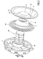
Figure 2 is a perspective elerational view of the loudspeaker ofFig.1 in an exploded view. - The electrodynamic loudspeaker according to the invention, shown in the Figures, comprises a
chassis 2, a movable body 4 and an electromagnetic actuator 6. For forming a loudspeaker unit according to the invention, the loudspeaker may be accommodated in a housing. To this end, thechassis 2 may be fixed in an appropriate opening in a wall of this housing. InFig. 1 , the housing is shown diagrammatically by means of a wall section 1 in broken lines. - The movable body 4 has a three-dimensional diaphragm structure comprising a central dome-
shaped diaphragm 8 and a cone-shaped diaphragm 10 concentrically arranged with respect to the dome-shaped diaphragm 8. The dome-shaped diaphragm 8 may be made of a metal, such as aluminium; reinforced plastics; pressed paper; or any other suitable material. Thediaphragm 8 has a sufficient stiffness and may be provided with a central opening 8a covered by a dust cap 9 of any suitable material, such as paper, plastics, or textile. The cone-shaped diaphragm 10 may be made of pressed paper, carbon fiber, polyglass, aluminium, or any other suitable material. The cone-shaped diaphragm 10 has aback portion 10b and afront portion 10f which is wider than theback portion 10b. The dome-shaped diaphragm 8 and the cone-shaped diaphragm 10 are mutually secured at theback portion 10b. For this reason, the cone-shaped diaphragm 10 has an innercircumferential edge 10i, while the dome-shaped diaphragm 8 has a corresponding outercircumferential rim 8o. The edge 10i and therim 8o preferably have round cross-sections so that theedge 10i and therim 8o fit each other. Theedge 10i and therim 8o are preferably glued to each other. - The loudspeaker further comprises a resilient suspension for suspending the movable body 4 from the
chassis 2 and for guiding the movable body along a translation axis T. The suspension includes a firstresilient element 12a and a secondresilient element 12b. The firstresilient element 12a is a ring-like spider, an innercircumferential brim 12a; of which is attached to theedge 10i and/or therim 8o and an outercircumferential brim 12ao is attached to thechassis 2. A glue may be used for both attachments. Thespider 12a may be a known flexible corrugated body and ensures that the movable body 4 can perform well-defined translation movements with respect to thechassis 2. - The second
resilient element 12b has a roll structure known per se and is formed, for example, from a bent rubber or foam annular strip. On its outer circumference, thesecond element 12b is secured, for example glued, to thechassis 2 and on its inner circumference to an outercircumferential edge 10o of the cone-shaped membrane 10. - The actuator 6 essentially comprises two elements, namely a stationary actuator part 6a which is fixed to the
chassis 2 and a translatable actuator part 6b which is connected to the movable body 4. One of the actuator parts - in this example the part 6a - is provided with apermanent magnet 13, in this example annular in shape and axially polarized, and the other actuator part - in this example the part 6b - is provided with amagnet coil 14. Thepermanent magnet 13 is formed from a neodymium-iron-boron alloy and forms amagnetic yoke 13a with soft iron portions of the stationary actuator part 6a, which yoke defines anair gap 16. Themagnet coil 14, being a cylindrical coil, also referred to as voice coil, is situated on acoil support 14a, being a sleeve in this example, which is fixed to the dome-shaped diagram 8. Alead wire 17 connects thecoil 14 by means of aconnector 18 which is adhered to thechassis 2. When energizing thecoil 14, both actuator parts 6a, 6b magnetically co-operate with each other over theair gap 16 for generating a driving force on the movable body 4 parallel to the translation axis T and thus on the dome-shapeddiaphragm 8 and the cone-shapeddiaphragm 10. - It is to be noted that the invention is not limited to the embodiment shown. For example, the dome-shaped diaphragm and the cone-shaped diaphragm may be formed as an integral combination, thus comprising or consisting of a single diaphragm structure. Moreover, the loudspeaker unit may not only comprise one or more speakers but also one or more passive radiators or bass reflex ports. Furthermore, the loudspeaker according to the invention is not limited to a certain power. For acoustical sound tuning purposes, the dome-shaped diaphragm may be provided with perforations and/or a coating. For the same purposes, the outer circumferential rim of the dome-shaped diaphragm does not need to be a back portion of the dome-shaped diaphragm, but may be a rim parallel to the back portion.
Claims (9)
- A loudspeaker provided with a chassis (2), a movable body (4), a resilient suspension for guiding the movable body with respect to the chassis along a translation axis, and an electric actuator (6) for driving the movable body along the translation axis, which movable body has a diaphragm structure comprising a central dome-shaped diaphragm (8) and a cone-shaped diaphragm (10) concentrically arranged with respect to the dome-shaped diaphragm, which cone-shaped diaphragm has a back portion (10b) and a front portion (10f) which is wider than the back portion, wherein both diaphragms are attached to each other , the cone-shaped diaphragm enveloping the dome-shaped diaphragm, and wherein the resilient suspension comprises a resilient element (12a) connecting the diaphragm structure to the chassis near the back portion of the cone-shaped diaphragm, and a further resilient element (12b) connecting the diaphragm structure to the chassis near the front portion of the cone-shaped diaphragm;
characterised in that a rim (8o) of the dome-shaped diaphragm is attached to a back edge (10i) of the back portion of the cone-shaped diaphragm. - A loudspeaker as claimed in claim 1, wherein the electric actuator (6) comprises a stationary part (6a) secured to the chassis (2) and a translatable part (6b) secured to the dome-shaped diaphragm (8).
- A loudspeaker as claimed in claim 1, wherein the back portion (10b) of the cone-shaped diaphragm (10) includes an inner circumferential edge (10i) to which an outer circumferential rim (8o) of the dome-shaped diaphragm (8) is connected.
- A loudspeaker as claimed in claim 3, wherein the resilient element (12a) of the resilient suspension includes an inner circumferential brim (12ai) which is connected to the inner circumferential edge (10i) of the cone-shaped diaphragm (10) and/or the outer circumferential rim (8o) of the dome-shaped diaphragm (8).
- A loudspeaker as claimed in claim 2, wherein the stationary part (6a) includes a magnetic yoke (13a) with a permanent magnet (13) and the translatable part (6b) includes a coil support with a voice coil (14), which coil extends in an air gap of the magnetic yoke and has a coil axis coinciding with the translation axis of the movable body (14).
- A loudspeaker as claimed in any one of claims 1 to 5 wherein the dome-shaped diaphragm (8) and the cone-shaped diaphragm (10) are formed as an integral combination.
- A diaphragm structure for use in the loudspeaker as claimed in any one of the preceding claims comprising a central dome-shaped diaphragm (8) and a cone-shaped diaphragm (10) concentrically arranged with respect to the dome-shaped diaphragm, which cone-shaped diaphragm has a back portion (10b) and a front portion (10f) which is wider than the back portion, wherein both diaphragms are attached to each other, the cone-shaped diaphragm enveloping the dome-shaped diaphragm, characterised in that a rim (8o) of the dome-shaped diaphragm is attached
to a back edge (10i) of the back portion of the cone-shaped diaphragm. - A diaphragm structure as claimed in claim 7 wherein the back portion of the cone-shaped diaphragm includes an inner circumferential edge to which an outer circumferential rim of the dome-shaped diaphragm is connected.
- A loudspeaker unit comprising the loudspeaker as claimed in any one of claims 1 to 6 and comprising a housing accommodating the loudspeaker.
Priority Applications (1)
| Application Number | Priority Date | Filing Date | Title |
|---|---|---|---|
| EP04744755A EP1658753B1 (en) | 2003-08-22 | 2004-08-06 | Loudspeaker having a composite diaphragm structure |
Applications Claiming Priority (3)
| Application Number | Priority Date | Filing Date | Title |
|---|---|---|---|
| EP03103214 | 2003-08-22 | ||
| PCT/IB2004/051413 WO2005020630A1 (en) | 2003-08-22 | 2004-08-06 | Loudspeaker having a composite diaphragm structure |
| EP04744755A EP1658753B1 (en) | 2003-08-22 | 2004-08-06 | Loudspeaker having a composite diaphragm structure |
Publications (2)
| Publication Number | Publication Date |
|---|---|
| EP1658753A1 EP1658753A1 (en) | 2006-05-24 |
| EP1658753B1 true EP1658753B1 (en) | 2012-05-23 |
Family
ID=34203252
Family Applications (1)
| Application Number | Title | Priority Date | Filing Date |
|---|---|---|---|
| EP04744755A Not-in-force EP1658753B1 (en) | 2003-08-22 | 2004-08-06 | Loudspeaker having a composite diaphragm structure |
Country Status (6)
| Country | Link |
|---|---|
| US (1) | US7570780B2 (en) |
| EP (1) | EP1658753B1 (en) |
| JP (1) | JP4675895B2 (en) |
| KR (1) | KR101139126B1 (en) |
| CN (1) | CN1839658B (en) |
| WO (1) | WO2005020630A1 (en) |
Families Citing this family (21)
| Publication number | Priority date | Publication date | Assignee | Title |
|---|---|---|---|---|
| US20100177925A1 (en) * | 2006-05-24 | 2010-07-15 | Pioneer Corporation | Speaker Device |
| AU2007273287A1 (en) * | 2006-07-12 | 2008-01-17 | Anders Sagren | High frequency diaphragm and voice coil assembly |
| GB2449842B (en) | 2007-05-03 | 2012-02-01 | Pss Belgium Nv | Loudspeaker with a stiffening element |
| WO2009012783A2 (en) * | 2007-07-25 | 2009-01-29 | Lars Goller Holding Aps | Cone tweeter membrane |
| US20090169049A1 (en) * | 2007-12-28 | 2009-07-02 | Szu-Wei Sun | Low Profile Audio Speaker |
| JP2009188791A (en) * | 2008-02-07 | 2009-08-20 | Pioneer Electronic Corp | Speaker device |
| JP2009200919A (en) * | 2008-02-22 | 2009-09-03 | Pioneer Electronic Corp | Speaker system |
| CN105872893A (en) * | 2008-07-24 | 2016-08-17 | 珍尼雷克公司 | Driving unit of nested combination loudspeaker |
| US8442259B2 (en) * | 2010-06-04 | 2013-05-14 | Beats Electronics, Llc | System for vibration confinement |
| US8824722B2 (en) * | 2010-06-28 | 2014-09-02 | Tsinghua University | Loudspeaker incorporating carbon nanotubes |
| US9232314B2 (en) | 2013-09-09 | 2016-01-05 | Sonos, Inc. | Loudspeaker configuration |
| US9066179B2 (en) | 2013-09-09 | 2015-06-23 | Sonos, Inc. | Loudspeaker assembly configuration |
| CN103945318A (en) * | 2014-04-09 | 2014-07-23 | 美特科技(苏州)有限公司 | Method for manufacturing composite vibrating diaphragm |
| TWI477159B (en) * | 2014-05-27 | 2015-03-11 | Cotron Corp | Vibrating element |
| US10136220B2 (en) * | 2016-04-08 | 2018-11-20 | Bluecom Co., Ltd. | Bluetooth neck band headset including vibration speaker |
| GB201714844D0 (en) | 2017-09-15 | 2017-11-01 | Airbus Defence & Space Ltd | Method of data transmission |
| CN108600931B (en) * | 2018-01-10 | 2020-09-08 | 菏泽韩升元电子股份有限公司 | Loudspeaker diaphragm, manufacturing method thereof and earphone using same |
| CN208258052U (en) * | 2018-04-28 | 2018-12-18 | 深圳市冠旭电子股份有限公司 | Metal vibration diaphragm and loudspeaker |
| CN110418253A (en) * | 2018-04-28 | 2019-11-05 | 深圳市冠旭电子股份有限公司 | Vibrating diaphragm and loudspeaker |
| CN114731473A (en) | 2019-11-19 | 2022-07-08 | 杜比实验室特许公司 | Acoustic transducer with drop ring connected at resonant node |
| GB202209544D0 (en) | 2022-06-29 | 2022-08-10 | Pss Belgium Nv | Bass loudspeaker |
Family Cites Families (17)
| Publication number | Priority date | Publication date | Assignee | Title |
|---|---|---|---|---|
| US3925626A (en) | 1974-02-22 | 1975-12-09 | Jr Robert John Stallings | Dynamic speaker having dome diaphragm and basket frequency |
| JPS5854560B2 (en) * | 1976-07-15 | 1983-12-05 | ソニー株式会社 | speaker |
| JPS5753198A (en) * | 1980-09-16 | 1982-03-30 | Toshiba Corp | Ring-shaped speaker |
| JPS57102296U (en) * | 1980-12-16 | 1982-06-23 | ||
| JPS59139791A (en) * | 1984-01-25 | 1984-08-10 | Matsushita Electric Ind Co Ltd | Passive radiator |
| JPS6153895A (en) * | 1984-08-23 | 1986-03-17 | Onkyo Corp | Speaker |
| JPS6282900A (en) * | 1985-10-08 | 1987-04-16 | Matsushita Electric Ind Co Ltd | Dome type diaphragm for speaker |
| JPS62116100A (en) * | 1985-11-15 | 1987-05-27 | Nippon Gakki Seizo Kk | Diaphragm for microphone |
| JPS62150997A (en) | 1985-12-24 | 1987-07-04 | Matsushita Electric Ind Co Ltd | Speaker |
| GB8603645D0 (en) * | 1986-02-14 | 1986-03-19 | Celestion Int Ltd | Loudspeakers |
| JPH0243895A (en) * | 1988-08-03 | 1990-02-14 | Matsushita Electric Ind Co Ltd | Speaker |
| JP3049570B2 (en) * | 1991-05-07 | 2000-06-05 | 株式会社オーディオテクニカ | Diaphragm for electroacoustic transducer and method for manufacturing the same |
| JPH0585197U (en) * | 1992-04-20 | 1993-11-16 | オンキヨー株式会社 | Speaker |
| WO1996014722A1 (en) * | 1994-11-04 | 1996-05-17 | Philips Electronics N.V. | Apparatus comprising a baffle and a loudspeaker, and loudspeaker for use in the apparatus |
| JPH08205283A (en) * | 1995-01-20 | 1996-08-09 | Fujitsu Ten Ltd | Thin speaker |
| JP4557412B2 (en) * | 2000-11-20 | 2010-10-06 | パナソニック株式会社 | Speaker |
| CN1388729A (en) * | 2002-07-01 | 2003-01-01 | 斯贝克电子(嘉善)有限公司 | Loudspeaker with two symmetrical magnetic paths, two coils and two centering support fins |
-
2004
- 2004-08-06 US US10/568,647 patent/US7570780B2/en not_active Expired - Fee Related
- 2004-08-06 EP EP04744755A patent/EP1658753B1/en not_active Not-in-force
- 2004-08-06 KR KR1020067003651A patent/KR101139126B1/en not_active IP Right Cessation
- 2004-08-06 CN CN2004800239356A patent/CN1839658B/en not_active Expired - Fee Related
- 2004-08-06 JP JP2006523728A patent/JP4675895B2/en not_active Expired - Fee Related
- 2004-08-06 WO PCT/IB2004/051413 patent/WO2005020630A1/en active Application Filing
Also Published As
| Publication number | Publication date |
|---|---|
| KR20060113887A (en) | 2006-11-03 |
| CN1839658A (en) | 2006-09-27 |
| US20060256996A1 (en) | 2006-11-16 |
| EP1658753A1 (en) | 2006-05-24 |
| WO2005020630A1 (en) | 2005-03-03 |
| CN1839658B (en) | 2012-08-08 |
| US7570780B2 (en) | 2009-08-04 |
| JP4675895B2 (en) | 2011-04-27 |
| JP2007503735A (en) | 2007-02-22 |
| KR101139126B1 (en) | 2012-04-30 |
Similar Documents
| Publication | Publication Date | Title |
|---|---|---|
| EP1658753B1 (en) | Loudspeaker having a composite diaphragm structure | |
| EP0843949B1 (en) | Electrodynamic loudspeaker and system comprising the loudspeaker | |
| KR20060069450A (en) | Loudspeaker with undulated membrane | |
| EP1410682B1 (en) | Low profile speaker and system | |
| WO2007135745A1 (en) | Speaker device | |
| US7899202B2 (en) | Loudspeaker with cone-coupled damper | |
| JP3812150B2 (en) | Speaker | |
| EP1654907B1 (en) | Shallow loudspeaker | |
| JP2005277874A (en) | Coaxial speaker device and manufacturing method thereof | |
| JP3930126B2 (en) | Speaker | |
| JP2010034988A (en) | Speaker system | |
| JP2015084522A (en) | Thin loudspeaker converter | |
| EP1737269B1 (en) | Shallow loudspeaker | |
| US5526441A (en) | Full range convex electrodynamic loudspeaker | |
| US7515724B2 (en) | Loudspeaker driver | |
| WO2021033226A1 (en) | Speaker unit and speaker curved diaphragm | |
| JP6989751B2 (en) | Dust cap and electrokinetic speaker using it | |
| WO2006072910A2 (en) | Loudspeaker having a movable cone body | |
| JP3629777B2 (en) | Speaker | |
| WO2006117716A1 (en) | Loudspeaker having a movable diaphragm | |
| WO2009122573A1 (en) | Speaker device | |
| JPH07203589A (en) | Bi-direction radiation speaker | |
| JP2004023297A (en) | Coil bobbin and conductivity-1 turn ring and speaker arrangement | |
| JP2002191088A (en) | Speaker | |
| JPH09312897A (en) | Electroacoustic transducer |
Legal Events
| Date | Code | Title | Description |
|---|---|---|---|
| PUAI | Public reference made under article 153(3) epc to a published international application that has entered the european phase |
Free format text: ORIGINAL CODE: 0009012 |
|
| 17P | Request for examination filed |
Effective date: 20060322 |
|
| AK | Designated contracting states |
Kind code of ref document: A1 Designated state(s): AT BE BG CH CY CZ DE DK EE ES FI FR GB GR HU IE IT LI LU MC NL PL PT RO SE SI SK TR |
|
| DAX | Request for extension of the european patent (deleted) | ||
| RAP1 | Party data changed (applicant data changed or rights of an application transferred) |
Owner name: PSS BELGIUM NV |
|
| 17Q | First examination report despatched |
Effective date: 20070711 |
|
| GRAP | Despatch of communication of intention to grant a patent |
Free format text: ORIGINAL CODE: EPIDOSNIGR1 |
|
| GRAS | Grant fee paid |
Free format text: ORIGINAL CODE: EPIDOSNIGR3 |
|
| GRAA | (expected) grant |
Free format text: ORIGINAL CODE: 0009210 |
|
| AK | Designated contracting states |
Kind code of ref document: B1 Designated state(s): AT BE BG CH CY CZ DE DK EE ES FI FR GB GR HU IE IT LI LU MC NL PL PT RO SE SI SK TR |
|
| REG | Reference to a national code |
Ref country code: GB Ref legal event code: FG4D |
|
| REG | Reference to a national code |
Ref country code: CH Ref legal event code: EP |
|
| REG | Reference to a national code |
Ref country code: AT Ref legal event code: REF Ref document number: 559576 Country of ref document: AT Kind code of ref document: T Effective date: 20120615 |
|
| REG | Reference to a national code |
Ref country code: IE Ref legal event code: FG4D |
|
| REG | Reference to a national code |
Ref country code: DE Ref legal event code: R096 Ref document number: 602004037897 Country of ref document: DE Effective date: 20120726 |
|
| REG | Reference to a national code |
Ref country code: NL Ref legal event code: VDEP Effective date: 20120523 |
|
| PG25 | Lapsed in a contracting state [announced via postgrant information from national office to epo] |
Ref country code: FI Free format text: LAPSE BECAUSE OF FAILURE TO SUBMIT A TRANSLATION OF THE DESCRIPTION OR TO PAY THE FEE WITHIN THE PRESCRIBED TIME-LIMIT Effective date: 20120523 Ref country code: CY Free format text: LAPSE BECAUSE OF FAILURE TO SUBMIT A TRANSLATION OF THE DESCRIPTION OR TO PAY THE FEE WITHIN THE PRESCRIBED TIME-LIMIT Effective date: 20120523 Ref country code: SE Free format text: LAPSE BECAUSE OF FAILURE TO SUBMIT A TRANSLATION OF THE DESCRIPTION OR TO PAY THE FEE WITHIN THE PRESCRIBED TIME-LIMIT Effective date: 20120523 |
|
| REG | Reference to a national code |
Ref country code: AT Ref legal event code: MK05 Ref document number: 559576 Country of ref document: AT Kind code of ref document: T Effective date: 20120523 |
|
| PG25 | Lapsed in a contracting state [announced via postgrant information from national office to epo] |
Ref country code: SI Free format text: LAPSE BECAUSE OF FAILURE TO SUBMIT A TRANSLATION OF THE DESCRIPTION OR TO PAY THE FEE WITHIN THE PRESCRIBED TIME-LIMIT Effective date: 20120523 Ref country code: GR Free format text: LAPSE BECAUSE OF FAILURE TO SUBMIT A TRANSLATION OF THE DESCRIPTION OR TO PAY THE FEE WITHIN THE PRESCRIBED TIME-LIMIT Effective date: 20120824 Ref country code: PT Free format text: LAPSE BECAUSE OF FAILURE TO SUBMIT A TRANSLATION OF THE DESCRIPTION OR TO PAY THE FEE WITHIN THE PRESCRIBED TIME-LIMIT Effective date: 20120924 |
|
| PG25 | Lapsed in a contracting state [announced via postgrant information from national office to epo] |
Ref country code: BE Free format text: LAPSE BECAUSE OF FAILURE TO SUBMIT A TRANSLATION OF THE DESCRIPTION OR TO PAY THE FEE WITHIN THE PRESCRIBED TIME-LIMIT Effective date: 20120523 |
|
| PG25 | Lapsed in a contracting state [announced via postgrant information from national office to epo] |
Ref country code: EE Free format text: LAPSE BECAUSE OF FAILURE TO SUBMIT A TRANSLATION OF THE DESCRIPTION OR TO PAY THE FEE WITHIN THE PRESCRIBED TIME-LIMIT Effective date: 20120523 Ref country code: DK Free format text: LAPSE BECAUSE OF FAILURE TO SUBMIT A TRANSLATION OF THE DESCRIPTION OR TO PAY THE FEE WITHIN THE PRESCRIBED TIME-LIMIT Effective date: 20120523 Ref country code: AT Free format text: LAPSE BECAUSE OF FAILURE TO SUBMIT A TRANSLATION OF THE DESCRIPTION OR TO PAY THE FEE WITHIN THE PRESCRIBED TIME-LIMIT Effective date: 20120523 Ref country code: RO Free format text: LAPSE BECAUSE OF FAILURE TO SUBMIT A TRANSLATION OF THE DESCRIPTION OR TO PAY THE FEE WITHIN THE PRESCRIBED TIME-LIMIT Effective date: 20120523 Ref country code: CZ Free format text: LAPSE BECAUSE OF FAILURE TO SUBMIT A TRANSLATION OF THE DESCRIPTION OR TO PAY THE FEE WITHIN THE PRESCRIBED TIME-LIMIT Effective date: 20120523 Ref country code: SK Free format text: LAPSE BECAUSE OF FAILURE TO SUBMIT A TRANSLATION OF THE DESCRIPTION OR TO PAY THE FEE WITHIN THE PRESCRIBED TIME-LIMIT Effective date: 20120523 Ref country code: NL Free format text: LAPSE BECAUSE OF FAILURE TO SUBMIT A TRANSLATION OF THE DESCRIPTION OR TO PAY THE FEE WITHIN THE PRESCRIBED TIME-LIMIT Effective date: 20120523 |
|
| PG25 | Lapsed in a contracting state [announced via postgrant information from national office to epo] |
Ref country code: IT Free format text: LAPSE BECAUSE OF FAILURE TO SUBMIT A TRANSLATION OF THE DESCRIPTION OR TO PAY THE FEE WITHIN THE PRESCRIBED TIME-LIMIT Effective date: 20120523 Ref country code: PL Free format text: LAPSE BECAUSE OF FAILURE TO SUBMIT A TRANSLATION OF THE DESCRIPTION OR TO PAY THE FEE WITHIN THE PRESCRIBED TIME-LIMIT Effective date: 20120523 |
|
| REG | Reference to a national code |
Ref country code: CH Ref legal event code: PL |
|
| PG25 | Lapsed in a contracting state [announced via postgrant information from national office to epo] |
Ref country code: MC Free format text: LAPSE BECAUSE OF NON-PAYMENT OF DUE FEES Effective date: 20120831 |
|
| PLBE | No opposition filed within time limit |
Free format text: ORIGINAL CODE: 0009261 |
|
| STAA | Information on the status of an ep patent application or granted ep patent |
Free format text: STATUS: NO OPPOSITION FILED WITHIN TIME LIMIT |
|
| PG25 | Lapsed in a contracting state [announced via postgrant information from national office to epo] |
Ref country code: ES Free format text: LAPSE BECAUSE OF FAILURE TO SUBMIT A TRANSLATION OF THE DESCRIPTION OR TO PAY THE FEE WITHIN THE PRESCRIBED TIME-LIMIT Effective date: 20120903 Ref country code: LI Free format text: LAPSE BECAUSE OF NON-PAYMENT OF DUE FEES Effective date: 20120831 Ref country code: CH Free format text: LAPSE BECAUSE OF NON-PAYMENT OF DUE FEES Effective date: 20120831 |
|
| 26N | No opposition filed |
Effective date: 20130226 |
|
| REG | Reference to a national code |
Ref country code: IE Ref legal event code: MM4A |
|
| REG | Reference to a national code |
Ref country code: DE Ref legal event code: R097 Ref document number: 602004037897 Country of ref document: DE Effective date: 20130226 |
|
| PG25 | Lapsed in a contracting state [announced via postgrant information from national office to epo] |
Ref country code: IE Free format text: LAPSE BECAUSE OF NON-PAYMENT OF DUE FEES Effective date: 20120806 Ref country code: BG Free format text: LAPSE BECAUSE OF FAILURE TO SUBMIT A TRANSLATION OF THE DESCRIPTION OR TO PAY THE FEE WITHIN THE PRESCRIBED TIME-LIMIT Effective date: 20120823 |
|
| PGFP | Annual fee paid to national office [announced via postgrant information from national office to epo] |
Ref country code: DE Payment date: 20130725 Year of fee payment: 10 |
|
| PGFP | Annual fee paid to national office [announced via postgrant information from national office to epo] |
Ref country code: FR Payment date: 20130725 Year of fee payment: 10 Ref country code: GB Payment date: 20130719 Year of fee payment: 10 |
|
| PG25 | Lapsed in a contracting state [announced via postgrant information from national office to epo] |
Ref country code: TR Free format text: LAPSE BECAUSE OF FAILURE TO SUBMIT A TRANSLATION OF THE DESCRIPTION OR TO PAY THE FEE WITHIN THE PRESCRIBED TIME-LIMIT Effective date: 20120523 |
|
| PG25 | Lapsed in a contracting state [announced via postgrant information from national office to epo] |
Ref country code: LU Free format text: LAPSE BECAUSE OF NON-PAYMENT OF DUE FEES Effective date: 20120806 |
|
| PG25 | Lapsed in a contracting state [announced via postgrant information from national office to epo] |
Ref country code: HU Free format text: LAPSE BECAUSE OF FAILURE TO SUBMIT A TRANSLATION OF THE DESCRIPTION OR TO PAY THE FEE WITHIN THE PRESCRIBED TIME-LIMIT Effective date: 20040806 |
|
| REG | Reference to a national code |
Ref country code: DE Ref legal event code: R119 Ref document number: 602004037897 Country of ref document: DE |
|
| GBPC | Gb: european patent ceased through non-payment of renewal fee |
Effective date: 20140806 |
|
| REG | Reference to a national code |
Ref country code: DE Ref legal event code: R119 Ref document number: 602004037897 Country of ref document: DE Effective date: 20150303 |
|
| REG | Reference to a national code |
Ref country code: FR Ref legal event code: ST Effective date: 20150430 |
|
| PG25 | Lapsed in a contracting state [announced via postgrant information from national office to epo] |
Ref country code: DE Free format text: LAPSE BECAUSE OF NON-PAYMENT OF DUE FEES Effective date: 20150303 Ref country code: GB Free format text: LAPSE BECAUSE OF NON-PAYMENT OF DUE FEES Effective date: 20140806 |
|
| PG25 | Lapsed in a contracting state [announced via postgrant information from national office to epo] |
Ref country code: FR Free format text: LAPSE BECAUSE OF NON-PAYMENT OF DUE FEES Effective date: 20140901 |