JP2009200919A - Speaker system - Google Patents

Speaker system Download PDF

Info

Publication number
JP2009200919A
JP2009200919A JP2008041482A JP2008041482A JP2009200919A JP 2009200919 A JP2009200919 A JP 2009200919A JP 2008041482 A JP2008041482 A JP 2008041482A JP 2008041482 A JP2008041482 A JP 2008041482A JP 2009200919 A JP2009200919 A JP 2009200919A
Authority
JP
Japan
Prior art keywords
diaphragm
voice coil
lead wire
speaker device
damper
Prior art date
Legal status (The legal status is an assumption and is not a legal conclusion. Google has not performed a legal analysis and makes no representation as to the accuracy of the status listed.)
Pending
Application number
JP2008041482A
Other languages
Japanese (ja)
Inventor
Hiroyuki Doi
寛幸 土肥
Shintaro Aradera
晋太郎 新寺
Current Assignee (The listed assignees may be inaccurate. Google has not performed a legal analysis and makes no representation or warranty as to the accuracy of the list.)
Tohoku Pioneer Corp
Pioneer Corp
Original Assignee
Tohoku Pioneer Corp
Pioneer Electronic Corp
Priority date (The priority date is an assumption and is not a legal conclusion. Google has not performed a legal analysis and makes no representation as to the accuracy of the date listed.)
Filing date
Publication date
Application filed by Tohoku Pioneer Corp, Pioneer Electronic Corp filed Critical Tohoku Pioneer Corp
Priority to JP2008041482A priority Critical patent/JP2009200919A/en
Publication of JP2009200919A publication Critical patent/JP2009200919A/en
Pending legal-status Critical Current

Links

Images

Abstract

<P>PROBLEM TO BE SOLVED: To suppress an adverse influence from being exerted upon acoustic characteristics such as interference with sonic waves from a diaphragm, by suppressing a lead wire connected to a voice coil from being brought into contact with respective parts of a speaker system to generate noise or short-circuiting, disconnection and the like from occurring. <P>SOLUTION: The speaker system includes a magnetic circuit 1, a frame 2, and a vibrating body 3. The frame 2 supports the magnetic circuit 1 and the vibrating body 3. The vibrating body 3 includes a diaphragm 21, a voice coil bobbin 23, a voice coil 24, and a lead wire 27. The diaphragm 21 includes a turning portion 21c from an inner circumferential part 21a to an outer circumferential part 21b. The voice coil bobbin 23 is mounted in the inner circumferential part of the diaphragm 21. The voice coil 24 is wound around a circumferential surface of the voice coil bobbin 23. The lead wire 27 is connected to the voice coil 24. On a back side of the diaphragm 21, a lead wire housing part 21da is formed that extends from the inner circumferential part 21a to the turning portion 21c. A part of the lead wire 27 is housed in the lead wire housing part 21da. <P>COPYRIGHT: (C)2009,JPO&INPIT

Description

本発明は、特に、携帯電話、携帯ラジオあるいはPDA(Personal Digital Assistants)等の携帯用電子機器に搭載されたり、自動車のドア内や液晶ディスプレイ等の平面型表示装置の筐体内等の限られた空間内に取り付けられたりする薄型のスピーカ装置に関する。   The present invention is particularly limited to be mounted on a portable electronic device such as a mobile phone, a portable radio or a PDA (Personal Digital Assistants), in a door of a car, or in a casing of a flat display device such as a liquid crystal display. The present invention relates to a thin speaker device that is mounted in a space.

従来のスピーカ装置に用いられるスピーカ用振動板には、コーン型を呈する振動板(以下、「コーン型振動板」という。)の表面又は裏面の全面に、所定の間隔を有して外周部からネック部の中心に向けて渦巻状のリブが一体的に形成されているものがある。このスピーカ用振動板では、上記リブに上記ネック部から外周方向に向けてボイスコイルのリード線引き出し用の凹溝が形成されている。このスピーカ用振動板では、上記凹溝の先端部分に外部リード線と結合させるための透孔が形成されている。この透孔は、コーン型振動板の表裏を貫通するものである。ボイスコイルのリード線は、上記透孔を介して直接コーン型振動板の裏面に引き出されるか又は、上記透孔にハトメ等が装着され、リード線と外部リード線とが結合される(例えば、特許文献1参照。)。ここで、リード線のうち、コーン型振動板の裏面に引き出された部分及び外部リード線を総称して、「引出線」と呼ぶことにする。以下、この技術を第1の従来例と呼ぶ。   A speaker diaphragm used in a conventional speaker device includes a cone-shaped diaphragm (hereinafter referred to as a “cone-shaped diaphragm”) on the entire surface of the front surface or the back surface thereof with a predetermined distance from the outer periphery. In some cases, spiral ribs are integrally formed toward the center of the neck portion. In this speaker diaphragm, a concave groove for drawing out the lead wire of the voice coil is formed in the rib from the neck portion toward the outer periphery. In this speaker diaphragm, a through hole for coupling with an external lead wire is formed at the tip of the concave groove. This through hole penetrates the front and back of the cone type diaphragm. The lead wire of the voice coil is directly drawn out to the back surface of the cone-type diaphragm through the through hole, or a grommet is attached to the through hole, and the lead wire and the external lead wire are coupled (for example, (See Patent Document 1). Here, of the lead wires, the portion drawn to the back surface of the cone-type diaphragm and the external lead wires are collectively referred to as “lead wires”. Hereinafter, this technique is referred to as a first conventional example.

また、従来の薄型のスピーカ装置には、内周部がボイスコイルボビンに連結され、外周部がエッジを介してフレームに連結されている振動板を有しているものがある。このスピーカ装置では、上記振動板は、内周部と外周部の間に頂部が形成されている。また、外周部が上記フレームに連結されるとともに、内周部が磁気回路又は上記プレートに連結されたダンパが設けられている。このダンパは、上記外周部と上記内周部の間において、上記振動板の上記頂部を支持している。さらに、上記ボイスコイルボビンに巻き回されたボイスコイルの両端は、それぞれボイスコイルボビン及び振動板に沿って引き出され、振動板の内周部近傍において一対のリード線とそれぞれ接続されている。上記一対のリード線は、振動板に形成された挿通孔内において挿通孔に接触しないように空中配線(スタイリング)され、挿通孔を経由してフレームに固定された正負の入力端子にそれぞれ接続されている(例えば、特許文献2参照。)。以下、この技術を第2の従来例と呼ぶ。   Some conventional thin speaker devices have a diaphragm having an inner peripheral portion connected to a voice coil bobbin and an outer peripheral portion connected to a frame via an edge. In this speaker device, the vibration plate has a top portion formed between the inner peripheral portion and the outer peripheral portion. In addition, a damper having an outer peripheral portion connected to the frame and an inner peripheral portion connected to a magnetic circuit or the plate is provided. The damper supports the top portion of the diaphragm between the outer peripheral portion and the inner peripheral portion. Further, both ends of the voice coil wound around the voice coil bobbin are pulled out along the voice coil bobbin and the diaphragm, respectively, and connected to a pair of lead wires in the vicinity of the inner peripheral portion of the diaphragm. The pair of lead wires are wired in the air (styling) so as not to contact the insertion hole in the insertion hole formed in the diaphragm, and are connected to the positive and negative input terminals fixed to the frame via the insertion hole, respectively. (For example, refer to Patent Document 2). Hereinafter, this technique is referred to as a second conventional example.

実開平2−8294公報(請求項1,請求項2、第3頁下から6行目〜第7頁第7行目、第1図,第2図)Japanese Utility Model Laid-Open No. 2-8294 (Claims 1, 2 and 6 from the bottom of the third page to the seventh line, the seventh line, FIGS. 1 and 2) 特許第3643855号公報(請求項3,[0023],[0032]〜[0055]、図1〜図3)Japanese Patent No. 3634855 (Claim 3, [0023], [0032] to [0055], FIGS. 1 to 3)

上記第1の従来例では、上記引出線がスピーカ装置を構成するヨークの外周側部、振動板又はダンパに接触し、異音が生じるおそれがある。また、上記第1の従来例において、ボイスコイルのリード線を上記透孔を介して直接コーン型振動板の裏面に引き出した場合、コーン型振動板の裏面に引き出された部分(引出線)がコーン型振動板の前面側に引出され、コーン型振動板から放射される音波と干渉(共振等)し、上記音波を打ち消す等、スピーカ装置の音響特性に悪影響を与えるおそれがある。さらに、上記第1の従来例では、上記ヨークの外周側部に引出線が接触等し、ショート又は断線等が発生するおそれがある。   In the first conventional example, there is a concern that the lead wire contacts the outer peripheral side portion of the yoke, the diaphragm or the damper constituting the speaker device, and abnormal noise is generated. In the first conventional example, when the lead wire of the voice coil is directly drawn out to the back surface of the cone type diaphragm through the through hole, the portion (leader line) drawn to the back surface of the cone type diaphragm is There is a risk of adversely affecting the acoustic characteristics of the speaker device, such as interference (resonance, etc.) with a sound wave that is drawn to the front surface side of the cone-type diaphragm and radiated from the cone-type diaphragm, and cancels the sound wave. Furthermore, in the first conventional example, there is a possibility that the lead wire contacts the outer peripheral side portion of the yoke, and a short circuit or disconnection occurs.

また、上記第2の従来例では、振動板に形成した挿通孔に接着剤等を充填して、リード線が振動板に固定され、且つ振動板の動きに伴って移動しないようにしているが、接着剤の充填が不十分な場合や、スピーカ装置に対して強い衝撃が与えられた場合、あるいは振動板の長期間にわたる振動等によって、振動板に対するリード線の固定が緩んでしまうおそれがある。このような場合、リード線が挿通孔に接触して異音が生じてしまう。   In the second conventional example, the insertion hole formed in the diaphragm is filled with an adhesive or the like so that the lead wire is fixed to the diaphragm and does not move with the movement of the diaphragm. When the adhesive is insufficiently filled, when a strong impact is applied to the speaker device, or when the diaphragm is vibrated over a long period of time, the lead wire may be loosely fixed to the diaphragm. . In such a case, the lead wire comes into contact with the insertion hole and noise is generated.

本発明は、上述した事情に鑑みてなされたものであり、上述のような問題を解決することを課題の一例とするものであり、これらの課題を解決することができるスピーカ装置を提供することを目的とする。   This invention is made | formed in view of the situation mentioned above, and makes it an example of a subject to solve the above problems, and provides the speaker apparatus which can solve these subjects. With the goal.

上記課題を解決するために、請求項1記載の発明に係るスピーカ装置は、振動体と、磁気回路と、前記振動体と前記磁気回路とを支持するフレームとを備え、前記振動体は、内周部から外周部までの間に折り返し部を有する振動板と、前記振動板の前記内周部に取り付けられたボイスコイルボビンと、前記ボイスコイルボビンの周面に巻き回されたボイスコイルと、前記ボイスコイルに接続される引出線とを有し、前記振動板の背面側には、前記内周部から前記折り返し部にかけて延在する引出線収容部が形成され、前記引出線収容部に前記引出線の一部が収容されていることを特徴としている。   In order to solve the above-described problem, a speaker device according to a first aspect of the present invention includes a vibrating body, a magnetic circuit, and a frame that supports the vibrating body and the magnetic circuit. A diaphragm having a folded portion between a peripheral part and an outer peripheral part, a voice coil bobbin attached to the inner peripheral part of the diaphragm, a voice coil wound around a peripheral surface of the voice coil bobbin, and the voice A lead wire connected to the coil, and on the back side of the diaphragm, a lead wire housing portion extending from the inner peripheral portion to the folded portion is formed, and the lead wire is provided in the lead wire housing portion. It is characterized in that a part of is housed.

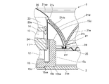
図1は、本発明の一実施の形態に係るスピーカ装置の構成を示す断面図、図2は、図1の部分拡大図である。また、図3は、図1に示すスピーカ装置を構成する振動板21の外観構成を示す斜視図である。このスピーカ装置は、磁気回路1と、フレーム2と、振動体3とを有している。   FIG. 1 is a cross-sectional view showing a configuration of a speaker device according to an embodiment of the present invention, and FIG. 2 is a partially enlarged view of FIG. FIG. 3 is a perspective view showing an external configuration of the diaphragm 21 constituting the speaker device shown in FIG. This speaker device has a magnetic circuit 1, a frame 2, and a vibrating body 3.

磁気回路1は、プレート11を同極同士が対向するように配置された2つの磁石12及び13で挟持して構成した反発型であって、内磁型である。また、磁石13の上面には、プレート14が載置されている。プレート11及び14は、例えば、鉄(例えば、ローカーボンスチール)等の軟質磁性材料からなる。プレート11及び14は、いずれも略円盤形状を呈しており、互いの外径は略等しい。プレート11の上端縁部及び下端縁部並びにプレート14の上端縁部には、面取りが施されている。プレート11の面取りは、いずれも、後述するボイスコイルボビン23との接触を避けるために、所定の間隙(クリアランス)を維持する必要上施されている。一方、プレート14の面取りは、後述するボイスコイルボビン23に穿設された貫通孔23aを介した空気の流通を容易にするために施されている。   The magnetic circuit 1 is a repulsive type constituted by sandwiching a plate 11 between two magnets 12 and 13 disposed so that the same poles face each other, and is an internal magnetic type. A plate 14 is placed on the upper surface of the magnet 13. The plates 11 and 14 are made of a soft magnetic material such as iron (for example, low carbon steel). Each of the plates 11 and 14 has a substantially disk shape, and their outer diameters are substantially equal. The upper end edge and lower end edge of the plate 11 and the upper end edge of the plate 14 are chamfered. The chamfering of the plate 11 is performed to maintain a predetermined gap (clearance) in order to avoid contact with a voice coil bobbin 23 described later. On the other hand, the chamfering of the plate 14 is performed in order to facilitate air circulation through a through hole 23a formed in a voice coil bobbin 23 described later.

磁石12及び13は、例えば、希土類系(例えば、ネオジム系)、サマリウム・コバルト系、アルニコ系、フェライト系磁石等の永久磁石等からなる。磁石12及び13は、同一の略円盤形状を呈しており、かつ、同一寸法である。磁石12及び13のそれぞれの外径は、プレート11の外径よりわずかに小さい。プレート11及び14と磁石12及び13とは、互いの厚み方向の中心軸が重なるように、例えば、接着剤等により固着されている。   The magnets 12 and 13 are made of, for example, a permanent magnet such as a rare earth (eg, neodymium), samarium / cobalt, alnico, or ferrite magnet. The magnets 12 and 13 have the same substantially disk shape and have the same dimensions. The outer diameter of each of the magnets 12 and 13 is slightly smaller than the outer diameter of the plate 11. The plates 11 and 14 and the magnets 12 and 13 are fixed by, for example, an adhesive or the like so that the central axes in the thickness direction of each other overlap each other.

一方、磁石12の下面には、ヨーク15が例えば、接着剤等により固着されている。ヨーク15は、例えば、純鉄、無酸素鋼、ケイ素鋼等の磁性材料からなる。ヨーク15は、底板部15aと、張出部15bと、外周側部15cとが一体に形成されて構成されている。底板部15aは、略円盤形状を呈している。底板部15aの外周部略中央からは、略円環形状を呈する張出部15bが略水平方向に張り出している。外周側部15cは、略円筒状を呈しており、張出部15bの外周部に略垂直に立設されている。底板部15aの外径は、磁石12及び13の外径に略等しい。外周側部15cの上端面の位置は、底板部15aの上面に積層された磁石12及びプレート11の上端面の位置に略等しい。また、外周側部15cの内径は、プレート11の外径よりわずかに大きく、外周側部15cの内周壁と、プレート11の外周壁との間には、磁気ギャップgが形成されている。さらに、外周側部15cの上端縁部には、面取りが施されている。この面取りが施されている部分を面取り部15dと称する。この面取り部15dは、後述する振動板21及び引出線27との接触を避けるために、所定の間隙(クリアランス)を維持する必要上、施されている。   On the other hand, the yoke 15 is fixed to the lower surface of the magnet 12 with, for example, an adhesive. The yoke 15 is made of a magnetic material such as pure iron, oxygen-free steel, or silicon steel. The yoke 15 is configured by integrally forming a bottom plate portion 15a, an overhang portion 15b, and an outer peripheral side portion 15c. The bottom plate portion 15a has a substantially disk shape. From the substantially center of the outer peripheral portion of the bottom plate portion 15a, a projecting portion 15b having a substantially annular shape projects in a substantially horizontal direction. The outer peripheral side portion 15c has a substantially cylindrical shape, and is erected substantially vertically on the outer peripheral portion of the overhang portion 15b. The outer diameter of the bottom plate portion 15a is substantially equal to the outer diameter of the magnets 12 and 13. The position of the upper end surface of the outer peripheral side portion 15c is substantially equal to the positions of the upper end surfaces of the magnet 12 and the plate 11 stacked on the upper surface of the bottom plate portion 15a. Further, the inner diameter of the outer peripheral side portion 15 c is slightly larger than the outer diameter of the plate 11, and a magnetic gap g is formed between the inner peripheral wall of the outer peripheral side portion 15 c and the outer peripheral wall of the plate 11. Furthermore, chamfering is applied to the upper edge of the outer peripheral side portion 15c. This chamfered portion is referred to as a chamfered portion 15d. The chamfered portion 15d is provided in order to maintain a predetermined gap (clearance) in order to avoid contact with a diaphragm 21 and a lead wire 27 described later.

フレーム2は、例えば、鉄系金属、非鉄金属又はそれらの合金、合成樹脂などから構成されている。鉄系金属としては、例えば、純鉄、無酸素鋼又はケイ素鋼等がある。非鉄金属としては、例えば、アルミニウム、マグネシウム又は亜鉛等がある。合成樹脂としては、例えば、ポリプロピレンなどのオレフィン系、ABS(アクリロニトリル・ブダジエン・スチレン)、ポリエチレンテレフタレート系などの熱可塑性樹脂に、補強用フィラーとしてガラス繊維又はフィブリル化したサーモトロピック液晶ポリエステル樹脂を添加してなるものなどがある。フレーム2は、例えば、鉄系金属を絞り成形したり、非鉄金属又はそれらの合金をダイキャスト成形したり、合成樹脂を射出成形したりして形成されている。   The frame 2 is made of, for example, a ferrous metal, a non-ferrous metal or an alloy thereof, a synthetic resin, or the like. Examples of the iron-based metal include pure iron, oxygen-free steel, and silicon steel. Examples of the non-ferrous metal include aluminum, magnesium, and zinc. As synthetic resins, for example, glass fibers or fibrillated thermotropic liquid crystal polyester resins are added as reinforcing fillers to thermoplastic resins such as olefins such as polypropylene, ABS (acrylonitrile, butadiene, styrene), and polyethylene terephthalate. There are things that become. The frame 2 is formed by, for example, drawing a ferrous metal, die casting a non-ferrous metal or an alloy thereof, or injection molding a synthetic resin.

フレーム2は、第1層2a、第2層2b及び第3層2cの3層が一体に構成されている。第1層2aの外径よりも第2層2bの外径が大きく、第2層2bの外径よりも第3層2cの外径が大きい。第1層2aは、略円環形状を呈する底板部2aaと、底板部2aaの外周部に略垂直に立設された略円筒形状を呈する外周側部2abとが一体に形成されて構成されている。フレーム2は、この底板部2aaにおいて下方に開口している。第2層2bは、略円環形状を呈する底板部2baと、底板部2baの外周部に略垂直に立設された略円筒形状を呈する外周側部2bbとが一体に形成されて構成されている。第2層2bの側面には、平面形状が略矩形状を呈する複数の開口部2bcがそれぞれ穿設されている。なお、図1には、一つの開口部2bcだけを示している。第3層2cは、略円環形状を呈する底板部2caと、底板部2caの外周部に略垂直に立設された略円筒形状を呈する外周側部2cbとが一体に形成されて構成されている。第3層2cの上端外周部には、略円環状を呈するフランジ2dが第3層2cと一体に形成されて構成されている。フレーム2は、図示しないが、このフランジ2dにおいて上方に開口している。   In the frame 2, three layers of a first layer 2a, a second layer 2b, and a third layer 2c are integrally formed. The outer diameter of the second layer 2b is larger than the outer diameter of the first layer 2a, and the outer diameter of the third layer 2c is larger than the outer diameter of the second layer 2b. The first layer 2a is formed by integrally forming a bottom plate portion 2aa having a substantially annular shape and an outer peripheral side portion 2ab having a substantially cylindrical shape standing substantially vertically on the outer peripheral portion of the bottom plate portion 2aa. Yes. The frame 2 opens downward in the bottom plate portion 2aa. The second layer 2b is formed by integrally forming a bottom plate portion 2ba having a substantially annular shape and a peripheral side portion 2bb having a substantially cylindrical shape standing substantially vertically on the outer peripheral portion of the bottom plate portion 2ba. Yes. A plurality of openings 2bc having a substantially rectangular planar shape are formed in the side surface of the second layer 2b. FIG. 1 shows only one opening 2bc. The third layer 2c is formed by integrally forming a bottom plate portion 2ca having a substantially annular shape and an outer peripheral side portion 2cb having a substantially cylindrical shape standing substantially vertically on the outer periphery of the bottom plate portion 2ca. Yes. A flange 2d having a substantially annular shape is formed integrally with the third layer 2c on the outer periphery of the upper end of the third layer 2c. Although not shown, the frame 2 opens upward in the flange 2d.

また、第1層2aの底板部2aaの内周部には、ヨーク15を構成する底板部15aの下部外周部15aaが係合され、下部外周部15aa及び張出部15bの下面15baと接着剤等により固着されている。これにより、フレーム2は、上記磁気回路1を支持している。また、フレーム2は、第2層2bの底板部2baと第3層2cの底板部2caにおいて後述する振動体3を支持している。   Further, the lower outer peripheral portion 15aa of the bottom plate portion 15a constituting the yoke 15 is engaged with the inner peripheral portion of the bottom plate portion 2aa of the first layer 2a, and the lower outer peripheral portion 15aa and the lower surface 15ba of the overhang portion 15b are bonded to the adhesive. And so on. As a result, the frame 2 supports the magnetic circuit 1. The frame 2 supports a vibrating body 3 to be described later on the bottom plate portion 2ba of the second layer 2b and the bottom plate portion 2ca of the third layer 2c.

振動体3は、振動板21と、エッジ22と、ボイスコイルボビン23と、ボイスコイル24と、ダンパー25と、センターキャップ26とを有している。振動板21は、平面形状が略円環状を呈している。振動板21の縦断面形状は、内周部21aから外周部21b側であって、かつ、スピーカ装置の背面側(音響放射方向に対し反対側)に向かいつつ、スピーカ装置の前面側(音響放射方向)が凸状となるように所定の曲線(以下、「第1の曲線」という。)を描いて湾曲して折り返し部21cに至る形状を呈している。また、振動板21の縦断面形状は、折り返し部21cから外周部21bに向かって、スピーカ装置の前面側(音響放射方向)が凸状となるように上記第1の曲線より緩やかな曲線(以下、「第2の曲線」という。)を描いて湾曲して外周部21bに至る形状を呈している。   The vibrating body 3 includes a diaphragm 21, an edge 22, a voice coil bobbin 23, a voice coil 24, a damper 25, and a center cap 26. The planar shape of the diaphragm 21 has a substantially annular shape. The longitudinal cross-sectional shape of the diaphragm 21 is from the inner peripheral part 21a to the outer peripheral part 21b side, and toward the rear side (opposite to the acoustic emission direction) of the speaker apparatus, while facing the front side (acoustic emission) of the speaker apparatus. A predetermined curve (hereinafter referred to as “first curve”) is drawn so that the direction is convex, and a shape reaching the folded portion 21c is exhibited. Further, the longitudinal cross-sectional shape of the diaphragm 21 is a curve (hereinafter referred to as a curve) that is gentler than the first curve so that the front side (acoustic radiation direction) of the speaker device is convex from the folded portion 21c toward the outer peripheral portion 21b. , Referred to as “second curve”), and is curved to reach the outer peripheral portion 21b.

ここで、振動板21の内周部21aから折り返し部21cまでを第1湾曲部21dと呼び、振動板21の折り返し部21cから外周部21bまでを第2湾曲部21eと呼ぶことにする。振動板21の平面形状において、内周部21aから折り返し部21cまでの直線距離と、折り返し部21cから外周部21bまでの直線距離の比は、例えば、1:3程度である。また、振動板21の折り返し部21cは、後述するように、ダンパー25の内周部近傍前面に接着剤28により固着されている。   Here, the part from the inner peripheral part 21a to the folded part 21c of the diaphragm 21 is referred to as a first curved part 21d, and the part from the folded part 21c to the outer peripheral part 21b of the diaphragm 21 is referred to as a second curved part 21e. In the planar shape of the diaphragm 21, the ratio of the linear distance from the inner peripheral portion 21a to the folded portion 21c and the linear distance from the folded portion 21c to the outer peripheral portion 21b is, for example, about 1: 3. Further, the folded portion 21 c of the diaphragm 21 is fixed to the front surface in the vicinity of the inner peripheral portion of the damper 25 with an adhesive 28 as will be described later.

振動板21の材料としては、例えば、紙、繊維を用いた織布、繊維を用いた編み物、不織布、繊維を用いた織布にシリコーン樹脂等からなる結合樹脂を含浸させたもの、合成樹脂、アクリル発泡体などがある。合成樹脂には、例えば、ポリプロピレン、ポリエチレン、ポリスチレン、ポリエチレンテレフタレート、ポリエチレンナフタレート、ポリメチルメタアクリレート、ポリカーボネイト、ポリアリレート、エポキシ樹脂等などがある。また、アクリル発泡体は、例えば、メタアクリル酸メチルと、メタアクリル酸と、スチレンと、無水マレイン酸と、メタアクリルアミドとを原料とする。   Examples of the material of the diaphragm 21 include paper, a woven fabric using fibers, a knitted fabric using fibers, a nonwoven fabric, a woven fabric using fibers impregnated with a binding resin made of a silicone resin, a synthetic resin, Examples include acrylic foam. Examples of the synthetic resin include polypropylene, polyethylene, polystyrene, polyethylene terephthalate, polyethylene naphthalate, polymethyl methacrylate, polycarbonate, polyarylate, and epoxy resin. The acrylic foam is made from, for example, methyl methacrylate, methacrylic acid, styrene, maleic anhydride, and methacrylamide.

振動板21を構成する第1湾曲部21dの前面(音響放射方向)の内周部21aから折り返し部21cまでには、複数個の引出線収容部21daが形成されている。図3の例では、3個の引出線収容部21daが点対称となる位置に形成されている。各引出線収容部21daは、引出線27が収容できれば良いので、断面形状は、第1湾曲部21dの背面側(音響放射方向に対し反対側)で凹形状となるのであれば、どのような形状を呈していても良い。引出線収容部21daの厚さは、振動板21の厚さと略等しい。このように構成するのは、振動板21の重量を大きくすることなく、感度を十分に確保するためである。各引出線収容部21daの下端には、引出線27をフレーム2を構成する第2層2b側に取り出すための引出部21fが形成されている。   A plurality of lead wire accommodating portions 21da are formed from the inner peripheral portion 21a to the folded portion 21c on the front surface (acoustic radiation direction) of the first curved portion 21d constituting the diaphragm 21. In the example of FIG. 3, the three leader line accommodating portions 21da are formed at positions that are point-symmetric. Since each lead wire accommodating portion 21da only needs to accommodate the lead wire 27, any cross-sectional shape can be used as long as it is concave on the back side (opposite to the acoustic radiation direction) of the first curved portion 21d. It may have a shape. The thickness of the lead wire accommodating portion 21da is substantially equal to the thickness of the diaphragm 21. The reason for this configuration is to ensure sufficient sensitivity without increasing the weight of the diaphragm 21. At the lower end of each lead wire accommodating portion 21da, a lead portion 21f for taking out the lead wire 27 to the second layer 2b side constituting the frame 2 is formed.

振動板21の内周部21aには、平面形状が略円形状を呈する開口21aaが形成されている。開口21aaには、略円筒形状を呈するボイスコイルボビン23の上端近傍外周面が接着剤等により固着されている。ボイスコイル23の外周面には、略円形状を呈する複数の貫通孔23aが穿設されている。各貫通孔23aは、スピーカ装置の内部と外部との間で空気を出入りさせるためのものである。すなわち、スピーカ装置の内部が密閉されている場合には、スピーカ装置内の空気が圧縮・膨張し、いわゆるバネ性を帯び、振動板3の動きが抑制され、振動体3の振動特性が著しく劣化してしまうので、貫通孔23aを設けてそれを抑止しているのである。   An opening 21aa having a substantially circular planar shape is formed in the inner peripheral portion 21a of the diaphragm 21. The outer peripheral surface near the upper end of the voice coil bobbin 23 having a substantially cylindrical shape is fixed to the opening 21aa with an adhesive or the like. A plurality of through holes 23 a having a substantially circular shape are formed on the outer peripheral surface of the voice coil 23. Each through-hole 23a is for letting air in and out between the inside and the outside of the speaker device. That is, when the inside of the speaker device is hermetically sealed, the air in the speaker device is compressed / expanded, has a so-called spring property, the movement of the diaphragm 3 is suppressed, and the vibration characteristics of the vibrating body 3 are significantly deteriorated. Therefore, the through hole 23a is provided to suppress it.

ボイスコイルボビン23の下端近傍外周面には、ボイスコイル24が巻き回されている。ボイスコイル24の両端は、図1及び図2に示すように、それぞれボイスコイルボビン23に沿って上方へ引き出され、例えば、ボイスコイルボビン23の上端近傍において一対の引出線27とそれぞれ電気的に接続されている。引出線27は、例えば、複数の細い電線を撚り合せて形成された屈曲に強い錦糸線からなる。各引出線27は、振動板21を構成する第1湾曲部21dに形成されている引出線収容部21daのいずれかに収容され、対応する引出線収容部21daの下端に形成されている引出部21fからフレーム2を構成する第2層2b側に引き出されている。引出線27が収容された引出線収容部21daには、例えば、接着剤等が充填され、引出線27が収容される引出線収容部21daから脱落することが抑止されている。フレーム2の第2層2bの略中央内周面には、略対称となる2箇所に、断面略L字状を呈する一対の端子29が取り付けられている。各端子29には、一対の引出線27の各一端がそれぞれ電気的に接続されている。   A voice coil 24 is wound around the outer peripheral surface near the lower end of the voice coil bobbin 23. As shown in FIGS. 1 and 2, both ends of the voice coil 24 are drawn upward along the voice coil bobbin 23, and are electrically connected to a pair of lead wires 27 near the upper end of the voice coil bobbin 23, for example. ing. The lead wire 27 is made of, for example, a tinsel wire that is strong against bending and formed by twisting a plurality of thin electric wires. Each leader line 27 is accommodated in one of the leader line accommodating parts 21da formed in the first curved part 21d constituting the diaphragm 21, and the leader part is formed at the lower end of the corresponding leader line accommodating part 21da. 21 f is drawn to the second layer 2 b side constituting the frame 2. The leader line accommodating portion 21da in which the leader line 27 is accommodated is filled with, for example, an adhesive or the like, and is prevented from dropping from the leader line accommodating portion 21da in which the leader line 27 is accommodated. A pair of terminals 29 having a substantially L-shaped cross section are attached to two substantially symmetric positions on the substantially central inner peripheral surface of the second layer 2 b of the frame 2. Each terminal 29 is electrically connected to one end of a pair of lead wires 27.

センターキャップ26は、例えば、ボイスコイルボビン23の内径に略等しい外径を有する曲面板によって形成されている。ボイスコイルボビン23の上端には、ボイスコイルボビン23の上端開口をふさぐとともに、スピーカ装置の前面側(音響放射方向)が凸状となるように、センターキャップ26が接着剤等により固着されている。このように、センターキャップ26は、ボイスコイルボビン23(又は、ボイスコイルボビン23及び振動板21)に連結されることにより、ボイスコイルボビン23及び振動板21の強度(剛性)を補強し、ボイスコイルボビン23及び振動板21の分割振動を極力抑えている。   The center cap 26 is formed of a curved plate having an outer diameter substantially equal to the inner diameter of the voice coil bobbin 23, for example. A center cap 26 is fixed to the upper end of the voice coil bobbin 23 with an adhesive or the like so that the upper end opening of the voice coil bobbin 23 is blocked and the front side (acoustic radiation direction) of the speaker device is convex. As described above, the center cap 26 is connected to the voice coil bobbin 23 (or the voice coil bobbin 23 and the diaphragm 21) to reinforce the strength (rigidity) of the voice coil bobbin 23 and the diaphragm 21. The divided vibration of the diaphragm 21 is suppressed as much as possible.

また、センターキャップ26は、振動板21と一体に振動するので、音響エネルギーの一部(主として高音域)の放射を担うとともに、振動板21の形状に起因した音波の干渉を位相補正してスピーカ装置の音響特性を調整する役割を有している。これにより、センターキャップ26は、振動板21の内周部21aに形成された開口21aaに起因した音響特性の影響を必要に応じて補正している。   Further, since the center cap 26 vibrates integrally with the diaphragm 21, the center cap 26 radiates a part of the acoustic energy (mainly the high sound range), and corrects the phase of the interference of the sound wave caused by the shape of the diaphragm 21. It has the role of adjusting the acoustic characteristics of the device. Accordingly, the center cap 26 corrects the influence of the acoustic characteristics caused by the opening 21aa formed in the inner peripheral portion 21a of the diaphragm 21 as necessary.

一方、振動板21の外周部21bの背面(音響放射方向に対し反対側)には、平面形状が略円環形状を呈するエッジ22の内周部22aが接着剤等により固着されている。エッジ22は、適度なコンプライアンスと剛性を兼ね備えている。エッジ22には、振動板21の外周部21bと同心円形状にコルゲーションが形成されている。すなわち、エッジ22の断面形状は、複数の凸部及び凹部とを有している。エッジ22の外周部下面は、フレーム2を構成する第3層2cの底板部2caの上面に接着剤等により固着されている。以上により、振動板21の外周部21bは、エッジ22を介してフレーム2に連結されている。すなわち、エッジ22は、振動板21をフレーム2に対し、弾性的に支持している。エッジ22の材料としては、上記した振動板21の材料の他、例えば、ゴム、ポリウレタン等の樹脂、発泡ゴム、発泡樹脂、又はポリプロピレン等の合成樹脂とタングステン等の金属とからなるハイブリッド材を用いても良い。   On the other hand, the inner peripheral portion 22a of the edge 22 having a substantially annular shape in plan view is fixed to the back surface of the outer peripheral portion 21b of the diaphragm 21 (opposite to the acoustic radiation direction) with an adhesive or the like. The edge 22 has appropriate compliance and rigidity. A corrugation is formed on the edge 22 in a concentric shape with the outer peripheral portion 21 b of the diaphragm 21. That is, the cross-sectional shape of the edge 22 has a plurality of convex portions and concave portions. The lower surface of the outer peripheral portion of the edge 22 is fixed to the upper surface of the bottom plate portion 2ca of the third layer 2c constituting the frame 2 with an adhesive or the like. As described above, the outer peripheral portion 21 b of the diaphragm 21 is connected to the frame 2 through the edge 22. That is, the edge 22 elastically supports the diaphragm 21 with respect to the frame 2. As the material of the edge 22, in addition to the material of the diaphragm 21, for example, a hybrid material made of a resin such as rubber or polyurethane, a foamed rubber, a foamed resin, or a synthetic resin such as polypropylene and a metal such as tungsten is used. May be.

ダンパー25は、適度なコンプライアンスと剛性を兼ね備えている。ダンパー25は、例えば、布にフェノール系樹脂等又はフェノール系樹脂と有機溶媒とからなる溶液などを含浸し、加熱成形により形成されている。ダンパー25は、平面形状が略円環形状を呈している。ダンパー25は、外周部から内周部へ向かって順に、直線部25aと、第1の曲線部25bと、第2の曲線部25cと、折り曲げ部25dとが一体に形成されて構成されている。   The damper 25 has appropriate compliance and rigidity. The damper 25 is formed, for example, by impregnating a cloth with a phenolic resin or the like, a solution made of a phenolic resin and an organic solvent, and the like, and by heat molding. The damper 25 has a substantially annular shape in plan view. The damper 25 includes a linear portion 25a, a first curved portion 25b, a second curved portion 25c, and a bent portion 25d that are integrally formed in order from the outer peripheral portion toward the inner peripheral portion. .

ダンパー25を構成する直線部25aの下面は、フレーム2を構成する第2層2bの底板部2baの上面に接着剤等により固着されている。第1の曲線部25b及び第2の曲線部25cは、振動板21の内周部21aと同様に、同心円形状を呈している。すなわち、ダンパー25の第1の曲線部25b及び第2の曲線部25cの各断面形状は、複数の凸部及び凹部とを有している。第2の曲線部25cの凹凸は、第1の曲線部25bの凹凸より小さく形成されている。これは、第2の曲線部25cの方が第1の曲線部25bよりもスピーカ装置の中心に近いため、振動板21や引出線27との接触等の可能性が高いからである。すなわち、第2の曲線部25cの凹凸を小さくすることにより、第2の曲線部25cと振動板21や引出線27との接触等を抑止することにより、この接触等に伴う異音の発生を抑止するためである。   The lower surface of the linear portion 25a constituting the damper 25 is fixed to the upper surface of the bottom plate portion 2ba of the second layer 2b constituting the frame 2 with an adhesive or the like. The first curved portion 25b and the second curved portion 25c have a concentric shape like the inner peripheral portion 21a of the diaphragm 21. That is, each cross-sectional shape of the first curved portion 25b and the second curved portion 25c of the damper 25 has a plurality of convex portions and concave portions. The unevenness of the second curved portion 25c is smaller than the unevenness of the first curved portion 25b. This is because the second curved portion 25c is closer to the center of the speaker device than the first curved portion 25b, so that there is a high possibility of contact with the diaphragm 21 and the lead wire 27. That is, by reducing the unevenness of the second curved portion 25c, by suppressing the contact between the second curved portion 25c and the diaphragm 21 and the lead wire 27, the generation of abnormal noise due to this contact or the like is prevented. This is for deterrence.

ダンパー25の内周部には、スピーカ装置の前面側(音響放射方向)に略直角に折れ曲がる折り曲げ部25dが形成されている。このダンパー25の折り曲げ部25dは、振動板21の折り返し部21cが接着剤28により固着されている。このように、ダンパー25の内周部に折り曲げ部25dを設けることにより、ボイスコイル24が配線されるボイスコイルボビン23の周面及び振動板21の引出線収容部21daに影響を及ぼすことなく、振動板21、特に、折り返し部21cとダンパー25との接合面積を確保することができ、接合力を大きくすることができる。また、ダンパー25の内周部に折り曲げ部25dを設けることにより、振動板21を大きな振幅にて振動させた場合でも、ダンパー25の内周部が、ヨーク15の外周側部15cに接触することが抑止できる。したがって、ダンパー25の内周部がヨーク15の外周側部15cに接触することによる異音の発生等を抑止することができる。   A bent portion 25d is formed on the inner peripheral portion of the damper 25. The bent portion 25d bends substantially at right angles to the front side (sound radiation direction) of the speaker device. In the bent portion 25 d of the damper 25, the folded portion 21 c of the vibration plate 21 is fixed by an adhesive 28. In this way, by providing the bent portion 25d on the inner peripheral portion of the damper 25, the vibration can be achieved without affecting the peripheral surface of the voice coil bobbin 23 to which the voice coil 24 is wired and the lead wire accommodating portion 21da of the diaphragm 21. It is possible to secure a bonding area between the plate 21, particularly the folded portion 21 c and the damper 25, and increase the bonding force. Further, by providing the bent portion 25 d on the inner peripheral portion of the damper 25, the inner peripheral portion of the damper 25 contacts the outer peripheral side portion 15 c of the yoke 15 even when the diaphragm 21 is vibrated with a large amplitude. Can be suppressed. Therefore, it is possible to suppress the occurrence of abnormal noise caused by the contact of the inner peripheral portion of the damper 25 with the outer peripheral side portion 15 c of the yoke 15.

一方、ダンパー25の外周部下面は、フレーム2を構成する第2層2bの底板部2baの上面に接着剤等により固着されている。以上により、振動板21の折り返し部21cは、ダンパー25を介してフレーム2に連結されている。すなわち、ダンパー25は、ダンパー25の内周部においてフレーム2に対し、振動板21の折り返し部21cを弾性的に支持している。   On the other hand, the lower surface of the outer peripheral portion of the damper 25 is fixed to the upper surface of the bottom plate portion 2ba of the second layer 2b constituting the frame 2 with an adhesive or the like. As described above, the folded portion 21 c of the diaphragm 21 is connected to the frame 2 via the damper 25. That is, the damper 25 elastically supports the folded portion 21 c of the diaphragm 21 with respect to the frame 2 at the inner peripheral portion of the damper 25.

これにより、ダンパー25は、スピーカ装置の静止状態(スピーカ装置が駆動されない状態)において、エッジ22とともに、振動板21、センターキャップ26、ボイスコイルボビン23及びボイスコイル24をそれぞれスピーカ装置の所定位置において弾性的に支持している。また、ダンパー25は、ボイスコイル24及びボイスコイルボビン23をプレート11及び14、磁石12及び13等の磁気回路1を構成する部材に接触させない所定位置で弾性的に保持している。   Accordingly, the damper 25 elastically moves the diaphragm 21, the center cap 26, the voice coil bobbin 23, and the voice coil 24 together with the edge 22 at predetermined positions of the speaker device in a stationary state of the speaker device (a state where the speaker device is not driven). Supportive. The damper 25 elastically holds the voice coil 24 and the voice coil bobbin 23 at a predetermined position where they do not come into contact with members constituting the magnetic circuit 1 such as the plates 11 and 14 and the magnets 12 and 13.

また、ダンパー25は、スピーカ装置の駆動状態においては、センターキャップ26、振動板21、ボイスコイルボビン23及びボイスコイル24を振動方向に沿って弾性的に支持する役目も担っている。   The damper 25 also has a role of elastically supporting the center cap 26, the diaphragm 21, the voice coil bobbin 23, and the voice coil 24 along the vibration direction in the driving state of the speaker device.

上記構成を有するスピーカ装置は、音声信号(音声電流)が供給されると、音声電流が一対の引出線27を介してボイスコイル24に供給される。一方、磁気回路1を構成する磁石12に基づく磁束と、磁石13に基づく磁束とは、それぞれプレート11の厚み方向の略中央に向かった後、合成されてプレート11の外周縁に向かい(径方向)、ボイスコイルボビン23及びボイスコイル24の中心軸方向に直交する方向へボイスコイルボビン23及びボイスコイル24を透過する。   In the speaker device having the above configuration, when an audio signal (audio current) is supplied, the audio current is supplied to the voice coil 24 via the pair of lead wires 27. On the other hand, the magnetic flux based on the magnet 12 constituting the magnetic circuit 1 and the magnetic flux based on the magnet 13 are combined toward the outer peripheral edge of the plate 11 (radial direction) after going toward the approximate center in the thickness direction of the plate 11. ), The voice coil bobbin 23 and the voice coil 24 are transmitted in a direction orthogonal to the central axis direction of the voice coil bobbin 23 and the voice coil 24.

したがって、上記した磁石12及び13に基づく合成磁束とボイスコイル24に流された音声電流との間の電磁気力(ローレンツ力)に基づいてスピーカ装置の中心軸方向の駆動力がボイスコイル24に誘起される。この駆動力は、ボイスコイルボビン23を介して振動板21に伝達される。振動板21は、この駆動力の作用を受けて、エッジ22及びダンパ25に弾性支持されつつ、振動し、音声電流に応じた音波を前面(音響放射方向)にある空間に向けて放射する。   Therefore, the driving force in the direction of the central axis of the speaker device is induced in the voice coil 24 based on the electromagnetic force (Lorentz force) between the combined magnetic flux based on the magnets 12 and 13 and the audio current passed through the voice coil 24. Is done. This driving force is transmitted to the diaphragm 21 via the voice coil bobbin 23. The vibration plate 21 receives the action of the driving force, vibrates while being elastically supported by the edge 22 and the damper 25, and radiates a sound wave corresponding to the sound current toward a space in the front surface (acoustic radiation direction).

この実施の形態に係るスピーカ装置は、磁気回路1と、フレーム2と、振動体3とを備えている。フレーム2は、磁気回路1と振動体3とを支持している。振動体3は、振動板21と、ボイスコイルボビン23と、ボイスコイル24と、引出線27とを有している。振動板21は、内周部21aから外周部21bまでの間に、折り返し部21cを有している。また、ボイスコイルボビン23は、振動板21の内周部に取り付けられている。ボイスコイル24は、ボイスコイルボビン23の外周面に巻き回されている。引出線27は、ボイスコイル24に接続されている。振動板21の背面側には、内周部21aから折り返し部21cにかけて延在する引出線収容部21daが形成されている。引出線収容部21daには、引出線27の一部が収容されている。   The speaker device according to this embodiment includes a magnetic circuit 1, a frame 2, and a vibrating body 3. The frame 2 supports the magnetic circuit 1 and the vibrating body 3. The vibrating body 3 includes a diaphragm 21, a voice coil bobbin 23, a voice coil 24, and a lead wire 27. The diaphragm 21 has a folded portion 21c between the inner peripheral portion 21a and the outer peripheral portion 21b. The voice coil bobbin 23 is attached to the inner peripheral portion of the diaphragm 21. The voice coil 24 is wound around the outer peripheral surface of the voice coil bobbin 23. The lead wire 27 is connected to the voice coil 24. On the back side of the diaphragm 21, a lead wire accommodating portion 21 da extending from the inner peripheral portion 21 a to the folded portion 21 c is formed. A part of the leader line 27 is accommodated in the leader line accommodating portion 21da.

したがって、引出線27がヨーク15を構成する外周側部15c、振動板21及びダンパー25に接触することを抑止することができ、異音の発生を抑止することができる。また、引出線27が振動板21の背面側に引き出されているので、振動板21から発せられる音波と、引出線27が振動板3と接触することで生じる異音とが干渉(共振等)し、上記音波を打ち消す等、スピーカ装置の音響特性に悪影響を与えることを抑止することができる。   Accordingly, it is possible to prevent the lead wire 27 from coming into contact with the outer peripheral side portion 15c constituting the yoke 15, the diaphragm 21, and the damper 25, and it is possible to suppress the generation of abnormal noise. In addition, since the lead wire 27 is drawn to the back side of the diaphragm 21, the sound wave emitted from the diaphragm 21 interferes with abnormal noise generated when the lead wire 27 contacts the diaphragm 3 (resonance, etc.). Thus, it is possible to suppress adverse effects on the acoustic characteristics of the speaker device, such as canceling the sound waves.

また、ヨーク15を構成する外周側部15cに引出線27が接触等し、ショート若しくは断線等が発生することを抑止することができる。また、引出線収容部21daに引出線27が収容されることにより、引出線27を引き回すためのスペースを削減することができ、振動体21の振幅を大きくすることができる。さらに、引出線収容部21daを設けることにより、振動板21の剛性が従来に比べて大きくなり、分割共振も含めた分割振動の発生を抑止することができる。   Further, it is possible to prevent the lead wire 27 from coming into contact with the outer peripheral side portion 15c constituting the yoke 15 to cause a short circuit or disconnection. Further, by accommodating the lead wire 27 in the lead wire accommodating portion 21da, a space for routing the lead wire 27 can be reduced, and the amplitude of the vibrating body 21 can be increased. Furthermore, by providing the lead wire accommodating portion 21da, the rigidity of the diaphragm 21 is increased as compared with the conventional case, and generation of divided vibration including divided resonance can be suppressed.

また、この実施の形態に係るスピーカ装置では、振動体21は、フレーム2に支持されるダンパー25を有している。振動板21は、折り返し部21cがダンパー25に取り付けられている。また、折り返し部21c近傍には、引出線収容部21daと連通する引出部21fが形成されている。そして、引出線収容部21daに収容された引出線27が引出部21fから引き出されている。   In the speaker device according to this embodiment, the vibrating body 21 has a damper 25 supported by the frame 2. The diaphragm 21 has a folded portion 21 c attached to the damper 25. In addition, a lead portion 21f that communicates with the lead wire accommodating portion 21da is formed in the vicinity of the folded portion 21c. And the leader line 27 accommodated in the leader line accommodating part 21da is pulled out from the leader part 21f.

このように、引出部21fを設けることにより、振動板21に貫通孔を穿設することなく、引出線27を容易に引出すことができ、さらに振動板21とダンパー25との接合面積が低減することを抑止することができる。これにより、スピーカ装置の信頼性が高められている。   Thus, by providing the lead-out portion 21f, the lead-out line 27 can be easily pulled out without making a through hole in the diaphragm 21, and the joining area between the diaphragm 21 and the damper 25 is reduced. Can be deterred. Thereby, the reliability of the speaker device is enhanced.

また、この実施の形態に係るスピーカ装置では、フレーム2に支持される端子29を備えている。そして、引出部21fから引出される引出線27は、振動板21の背面とダンパー25との間を引き回されて端子29に接続されている。このように、引出線27を引き回すスペースを、振動板21とダンパー25との間に設け、かつ、振動板21の折り返し部21cよりも外側に設けることにより、振動板21が振動するスペースを十分に確保することができ、さらに振動板21を大きな振幅にて振動させることができる。   Further, the speaker device according to this embodiment includes a terminal 29 supported by the frame 2. The lead line 27 drawn from the lead portion 21 f is connected between the back surface of the diaphragm 21 and the damper 25 and connected to the terminal 29. Thus, by providing a space for routing the lead wire 27 between the diaphragm 21 and the damper 25 and outside the folded portion 21c of the diaphragm 21, a sufficient space for the diaphragm 21 to vibrate is provided. In addition, the diaphragm 21 can be vibrated with a large amplitude.

また、この実施の形態に係るスピーカ装置では、引出線収容部21daは、振動板21の前面側が凸状となるように形成されている。引出線収容部21daをこのような形状にすることにより、容易に引出線27を収容することができるとともに、振動板21の剛性を大きくすることができ、分割振動(分割共振等)の発生を抑止することができる。   Further, in the speaker device according to this embodiment, the lead wire accommodating portion 21da is formed so that the front side of the diaphragm 21 is convex. By making the lead wire accommodating portion 21da into such a shape, the lead wire 27 can be easily accommodated, the rigidity of the diaphragm 21 can be increased, and split vibrations (split resonance, etc.) are generated. Can be deterred.

また、この実施の形態に係るスピーカ装置では、ダンパー25の内周部には、折り曲げ部25dが形成されているとともに、ダンパー25の折り曲げ部25dは、振動板21の折り返し部21cに取り付けられている。このように構成することにより、ボイスコイル24が配線されるボイスコイルボビン23の周面及び振動板21の引出線収容部21daに影響を及ぼすことなく、振動板21、特に、折り返し部21cとダンパー25との接合面積を確保することができ、接合力を大きくすることができる。また、ダンパー25の内周部に折り曲げ部25dを設けることにより、振動板21を大きな振幅にて振動させた場合でも、ダンパー25の内周部が、ヨーク15の外周側部15cに接触することがない。したがって、ダンパー25の内周部がヨーク15の外周側部15cに接触することによる異音の発生等を抑止することができる。   In the speaker device according to this embodiment, a bent portion 25 d is formed on the inner peripheral portion of the damper 25, and the bent portion 25 d of the damper 25 is attached to the folded portion 21 c of the diaphragm 21. Yes. With this configuration, the diaphragm 21, particularly the folded portion 21 c and the damper 25, are not affected without affecting the peripheral surface of the voice coil bobbin 23 to which the voice coil 24 is wired and the lead wire accommodating portion 21 da of the diaphragm 21. The bonding area can be ensured and the bonding force can be increased. Further, by providing the bent portion 25 d on the inner peripheral portion of the damper 25, the inner peripheral portion of the damper 25 contacts the outer peripheral side portion 15 c of the yoke 15 even when the diaphragm 21 is vibrated with a large amplitude. There is no. Therefore, it is possible to suppress the occurrence of abnormal noise caused by the contact of the inner peripheral portion of the damper 25 with the outer peripheral side portion 15 c of the yoke 15.

また、この実施の形態に係るスピーカ装置では、ダンパー25は、外周部から内周部へ向かって順に、フレーム2に取り付けられる直線部25aと、第1の曲線部25bと、凹凸が第1の曲線部25bの凹凸より小さく形成された第2の曲線部25cとが一体に形成されて構成されている。このように構成することにより、第2の曲線部25cと振動板21や引出線27との接触等を抑止することができ、この接触等に伴う異音の発生を抑止することができる。   Further, in the speaker device according to this embodiment, the damper 25 has a linear portion 25a attached to the frame 2 in order from the outer peripheral portion to the inner peripheral portion, the first curved portion 25b, and the first concave and convex portions. The second curved portion 25c formed smaller than the unevenness of the curved portion 25b is integrally formed. By comprising in this way, the contact etc. with the 2nd curve part 25c, the diaphragm 21, and the leader line 27 can be suppressed, and generation | occurrence | production of the noise accompanying this contact etc. can be suppressed.

また、この実施の形態では、振動板21は、上記した構造を有し、その内周部から外周部にわたる振動面が折り返し部21cで折り返されて形成されている。すなわち、折り返し部21cは、ボイスコイル24の下端と略等しい高さ又はボイスコイル24の下端より下方に位置している。このため、折り返し部21cから外周部21bまでの高さが振動板21の全高となる。したがって、振動板21の全高は、同じ口径(振動板の外径)、ボイスコイル径(振動板の内周部)を有する従来のコーン形振動板に比べて小さく形成することができる。これにより、本実施の形態に係るスピーカ装置は、振動板21の全高を小さく抑えることができるので、薄型に形成することができる。   Moreover, in this embodiment, the diaphragm 21 has the above-described structure, and a vibration surface extending from the inner peripheral portion to the outer peripheral portion is folded back by the folded portion 21c. That is, the folded portion 21 c is located at a height substantially equal to the lower end of the voice coil 24 or below the lower end of the voice coil 24. For this reason, the height from the folded portion 21 c to the outer peripheral portion 21 b is the total height of the diaphragm 21. Therefore, the overall height of the diaphragm 21 can be made smaller than that of a conventional cone diaphragm having the same aperture (outer diameter of the diaphragm) and voice coil diameter (inner peripheral portion of the diaphragm). Thereby, the speaker device according to the present embodiment can be reduced in thickness because the overall height of the diaphragm 21 can be kept small.

また、この実施の形態に係るスピーカ装置は、ボイスコイルボビン23にダンパ25が固定されていないので、振動時にダンパ25がプレート13にぶつかることがない。この結果、スピーカ装置の最大振幅を大きくすることができるとともに、ボイスコイルボビン23の全高を小さく抑えることができるので、スピーカ装置を薄型に形成することができる。   In the speaker device according to this embodiment, since the damper 25 is not fixed to the voice coil bobbin 23, the damper 25 does not hit the plate 13 during vibration. As a result, the maximum amplitude of the speaker device can be increased and the overall height of the voice coil bobbin 23 can be kept small, so that the speaker device can be formed thin.

また、この実施の形態では、図1に示すように、振動板21の折り返し部21cを弾性支持するダンパ25の高さ位置を、電磁気力の作用にて駆動されるボイスコイル24の高さ位置に近くすることができる。さらに、振動板21をボイスコイルボビン23の外径と略同軸であって、ボイスコイルボビン23の外径よりも大きな円環状を呈する折り返し部21cによって支持するようにしている。したがって、振動板21、ボイスコイルボビン23及びボイスコイル24の振動方向における弾性支持が安定し、これによりスピーカ装置の駆動時においてローリング現象が発生しにくくなる。   Further, in this embodiment, as shown in FIG. 1, the height position of the damper 25 that elastically supports the folded portion 21c of the diaphragm 21 is set to the height position of the voice coil 24 driven by the action of electromagnetic force. Can be close to. Further, the diaphragm 21 is supported by a folded portion 21 c that is substantially coaxial with the outer diameter of the voice coil bobbin 23 and has an annular shape larger than the outer diameter of the voice coil bobbin 23. Therefore, the elastic support in the vibration direction of the diaphragm 21, the voice coil bobbin 23, and the voice coil 24 is stabilized, so that the rolling phenomenon is less likely to occur when the speaker device is driven.

以上説明したように、スピーカ装置の駆動時において、振動板21、ボイスコイルボビン23及びボイスコイル24が安定して振動するので、振動板21においてローリング現象が発生しにくくなり、ボイスコイルボビン23及びボイスコイル24が磁石12やプレート13に接触することがないので、その分、大きな音声電流を入力し、振動板21を大きな振幅にて振動させることができる。   As described above, since the diaphragm 21, the voice coil bobbin 23, and the voice coil 24 stably vibrate when the speaker device is driven, the rolling phenomenon is less likely to occur in the diaphragm 21, and the voice coil bobbin 23 and the voice coil are not generated. Since 24 does not come into contact with the magnet 12 or the plate 13, it is possible to input a large sound current and vibrate the diaphragm 21 with a large amplitude.

以上、本発明の実施の形態について図面を参照して詳述してきたが、具体的な構成はこの実施の形態に限られるものではなく、本発明の要旨を逸脱しない範囲の設計の変更等があっても本発明に含まれる。
例えば、上述の実施の形態では、ダンパー25は、振動板21の外周部21bと同心円形状にコルゲーションが形成されている例を示したが、これに限定されず、ダンパー25にはコルゲーションを形成しなくても良い。同様に、上述の実施の形態では、エッジ22は、振動板21の外周部21bと同心円形状に複数のコルゲーションが形成されている例を示したが、これに限定されず、エッジ22には一つのコルゲーションが形成されていても良い。
The embodiment of the present invention has been described in detail with reference to the drawings. However, the specific configuration is not limited to this embodiment, and design changes and the like within a scope not departing from the gist of the present invention are possible. Even if it exists, it is included in this invention.
For example, in the above-described embodiment, the damper 25 has an example in which the corrugation is formed concentrically with the outer peripheral portion 21b of the diaphragm 21, but the invention is not limited thereto, and the damper 25 forms the corrugation. It is not necessary. Similarly, in the above-described embodiment, the example in which the edge 22 is formed with a plurality of corrugations concentrically with the outer peripheral portion 21b of the diaphragm 21 is not limited thereto. Two corrugations may be formed.

また、上述の実施の形態では、スピーカ装置の平面形状が略円形状を呈している例を示したが、これに限定されず、スピーカ装置の平面形状は略矩形状を呈していても良い。さらに、上述の実施の形態では、スピーカ装置の平面形状が略円形状を呈しているため、ヨーク15は、いずれも略円盤形状を呈する底板部15a及び張出部15b並びに略円筒形状を呈する外周側部15cを有している例を示したが、これに限定されない。例えば、スピーカ装置の平面形状が略矩形状を呈している場合には、ヨーク15は、略平板形状を呈していても良い。   In the above-described embodiment, an example in which the planar shape of the speaker device has a substantially circular shape has been described. However, the present invention is not limited thereto, and the planar shape of the speaker device may have a substantially rectangular shape. Furthermore, in the above-described embodiment, since the planar shape of the speaker device has a substantially circular shape, the yoke 15 has a bottom plate portion 15a and a projecting portion 15b each having a substantially disk shape, and an outer periphery having a substantially cylindrical shape. Although the example which has the side part 15c was shown, it is not limited to this. For example, when the planar shape of the speaker device has a substantially rectangular shape, the yoke 15 may have a substantially flat plate shape.

本発明の一実施の形態に係るスピーカ装置の構成を示す断面図である。It is sectional drawing which shows the structure of the speaker apparatus which concerns on one embodiment of this invention. 図1の部分拡大図である。It is the elements on larger scale of FIG. 図1に示すスピーカ装置を構成する振動板の外観構成を示す斜視図である。It is a perspective view which shows the external appearance structure of the diaphragm which comprises the speaker apparatus shown in FIG.

符号の説明Explanation of symbols

1…磁気回路、2…フレーム、2a…第1層、2aa,2ba,2ca…底板部、2ab,2bb,2cb…外周側部、2b…第2層、2bc…開口部、2c…第3層、2d…フランジ、3…振動体、11,14…プレート、12,13…磁石、15…ヨーク、15a…底板部、15aa…下部外周部、15b…張出部、15ba…下面、15c…外周側部、15d…面取り部、21…振動板、21a…内周部、21aa…開口、21b…外周部、21c…折り返し部、21d…第1湾曲部、21da…引出線収容部、21e…第2湾曲部、21f…引出部、22…エッジ、22a…内周部、23…ボイスコイルボビン、23a…貫通孔、24…ボイスコイル、25…ダンパー、25a…直線部、25b…第1の曲線部、25c…第2の曲線部、25d…折り曲げ部、26…センターキャップ、27…引出線、28…接着剤、29…端子   DESCRIPTION OF SYMBOLS 1 ... Magnetic circuit, 2 ... Frame, 2a ... 1st layer, 2aa, 2ba, 2ca ... Bottom plate part, 2ab, 2bb, 2cb ... Outer peripheral side part, 2b ... 2nd layer, 2bc ... Opening part, 2c ... 3rd layer 2d ... flange, 3 ... vibrating body, 11,14 ... plate, 12,13 ... magnet, 15 ... yoke, 15a ... bottom plate, 15aa ... lower outer periphery, 15b ... overhang, 15ba ... lower surface, 15c ... outer Side part, 15d ... Chamfered part, 21 ... Diaphragm, 21a ... Inner peripheral part, 21aa ... Opening, 21b ... Outer peripheral part, 21c ... Folded part, 21d ... First curved part, 21da ... Lead wire accommodating part, 21e ... First 2 curved portions, 21f ... drawing portion, 22 ... edge, 22a ... inner peripheral portion, 23 ... voice coil bobbin, 23a ... through hole, 24 ... voice coil, 25 ... damper, 25a ... straight portion, 25b ... first curved portion , 25c ... second curve , 25d ... bent portion, 26 ... center cap, 27 ... lead wire, 28 ... adhesive, 29 ... terminal

Claims (11)

振動体と、磁気回路と、前記振動体と前記磁気回路とを支持するフレームとを備え、
前記振動体は、内周部から外周部までの間に折り返し部を有する振動板と、前記振動板の前記内周部に取り付けられたボイスコイルボビンと、前記ボイスコイルボビンの周面に巻き回されたボイスコイルと、前記ボイスコイルに接続される引出線とを有し、
前記振動板の背面側には、前記内周部から前記折り返し部にかけて延在する引出線収容部が形成され、
前記引出線収容部に前記引出線の一部が収容されている
ことを特徴とするスピーカ装置。
Comprising a vibrating body, a magnetic circuit, and a frame that supports the vibrating body and the magnetic circuit;
The vibrating body is wound around a diaphragm having a folded portion between an inner periphery and an outer periphery, a voice coil bobbin attached to the inner periphery of the diaphragm, and a peripheral surface of the voice coil bobbin A voice coil, and a lead wire connected to the voice coil;
On the back side of the diaphragm, a lead wire accommodating portion extending from the inner peripheral portion to the folded portion is formed,
A part of the leader line is accommodated in the leader line accommodating part.
前記振動体は、前記フレームに支持されるダンパーを有し、
前記振動板は、前記折り返し部が前記ダンパーに取り付けられるとともに、前記折り返し部近傍には、前記引出線収容部と連通する引出部が形成され、前記引出線収容部に収容された前記引出線が前記引出部から引き出されている
ことを特徴とする請求項1に記載されるスピーカ装置。
The vibrator has a damper supported by the frame,
In the diaphragm, the folded portion is attached to the damper, and in the vicinity of the folded portion, a lead portion communicating with the lead wire accommodating portion is formed, and the lead wire accommodated in the lead wire accommodating portion is The speaker device according to claim 1, wherein the speaker device is pulled out from the drawing portion.
前記フレームに支持される端子を備え、
前記引出部から引出される前記引出線は、前記振動板の背面と前記ダンパーとの間を引き回されて前記端子に接続されている
ことを特徴とする請求項2に記載されるスピーカ装置。
Comprising a terminal supported by the frame;
3. The speaker device according to claim 2, wherein the lead-out line led out from the lead-out portion is routed between a back surface of the diaphragm and the damper and connected to the terminal.
前記引出線収容部は、前記振動板の前面側が凸状となるように形成されている
ことを特徴とする請求項1乃至3のいずれかに記載されるスピーカ装置。
The speaker device according to any one of claims 1 to 3, wherein the lead wire accommodating portion is formed so that a front side of the diaphragm is convex.
前記ダンパーの内周部には、折り曲げ部が形成されている
ことを特徴とする請求項2乃至4のいずれかに記載されるスピーカ装置。
The speaker device according to any one of claims 2 to 4, wherein a bent portion is formed on an inner peripheral portion of the damper.
前記ダンパーの前記折り曲げ部は、前記振動板の前記折り返し部に取り付けられている
ことを特徴とする請求項5に記載されるスピーカ装置。
The speaker device according to claim 5, wherein the bent portion of the damper is attached to the folded portion of the diaphragm.
前記ダンパーは、外周部から前記内周部へ向かって順に、前記フレームに取り付けられる直線部と、第1の曲線部と、凹凸が前記第1の曲線部の凹凸より小さく形成された第2の曲線部とが一体に形成されて構成されている
ことを特徴とする請求項2乃至6のいずれかに記載されるスピーカ装置。
The damper includes a linear portion attached to the frame, a first curved portion, and a second portion in which the unevenness is smaller than the unevenness of the first curved portion, in order from the outer peripheral portion to the inner peripheral portion. The speaker device according to any one of claims 2 to 6, wherein the curved portion is integrally formed.
前記引出線収容部の厚さは、前記振動板の厚さと略等しい
ことを特徴とする請求項1乃至7のいずれかに記載されるスピーカ装置。
8. The speaker device according to claim 1, wherein a thickness of the lead wire accommodating portion is substantially equal to a thickness of the diaphragm.
前記磁気回路は、ヨークと、磁石と、プレートとを有し、
前記ヨークは、底板部と、前記底板部を囲む外周側部とを有し、
前記外周側部の上端縁部には、面取りが施されている
ことを特徴とする請求項1乃至8のいずれかに記載されるスピーカ装置。
The magnetic circuit has a yoke, a magnet, and a plate,
The yoke has a bottom plate portion and an outer peripheral side portion surrounding the bottom plate portion,
The speaker device according to any one of claims 1 to 8, wherein the upper end edge of the outer peripheral side portion is chamfered.
前記振動体は、エッジを備え、
前記振動板は、前記エッジを介して前記フレームに支持されている
ことを特徴とする請求項1乃至9のいずれかに記載されるスピーカ装置。
The vibrating body includes an edge,
The speaker device according to any one of claims 1 to 9, wherein the diaphragm is supported by the frame via the edge.
前記振動体は、センターキャップを有し、
前記振動板の前記内周部に前記センターキャップの外周部が取り付けられている
ことを特徴とする請求項1乃至10のいずれかに記載されるスピーカ装置。
The vibrator has a center cap,
The speaker device according to any one of claims 1 to 10, wherein an outer peripheral portion of the center cap is attached to the inner peripheral portion of the diaphragm.
JP2008041482A 2008-02-22 2008-02-22 Speaker system Pending JP2009200919A (en)

Priority Applications (1)

Application Number Priority Date Filing Date Title
JP2008041482A JP2009200919A (en) 2008-02-22 2008-02-22 Speaker system

Applications Claiming Priority (1)

Application Number Priority Date Filing Date Title
JP2008041482A JP2009200919A (en) 2008-02-22 2008-02-22 Speaker system

Publications (1)

Publication Number Publication Date
JP2009200919A true JP2009200919A (en) 2009-09-03

Family

ID=41143927

Family Applications (1)

Application Number Title Priority Date Filing Date
JP2008041482A Pending JP2009200919A (en) 2008-02-22 2008-02-22 Speaker system

Country Status (1)

Country Link
JP (1) JP2009200919A (en)

Cited By (5)

* Cited by examiner, † Cited by third party
Publication number Priority date Publication date Assignee Title
EP2174984A1 (en) 2008-09-30 2010-04-14 Shin-Etsu Chemical Co., Ltd. Silicone resin composition for optical semiconductor devices
WO2013107071A1 (en) * 2012-01-19 2013-07-25 歌尔声学股份有限公司 Acoustic generator
KR101354442B1 (en) 2013-12-18 2014-01-27 주식회사 블루콤 Thin type micro speaker using augmented structure of magnetic force
JP2015080121A (en) * 2013-10-18 2015-04-23 オンキヨー株式会社 Electrodynamic speaker
US9628884B2 (en) 2015-01-30 2017-04-18 Bose Corporation Routing conductors to electro-acoustic transducer voice coils

Citations (4)

* Cited by examiner, † Cited by third party
Publication number Priority date Publication date Assignee Title
JPH01159500U (en) * 1988-04-21 1989-11-06
JPH028294U (en) * 1988-06-30 1990-01-19
JP2007503735A (en) * 2003-08-22 2007-02-22 コーニンクレッカ フィリップス エレクトロニクス エヌ ヴィ Speaker having a composite diaphragm structure
WO2007135745A1 (en) * 2006-05-24 2007-11-29 Pioneer Corporation Speaker device

Patent Citations (4)

* Cited by examiner, † Cited by third party
Publication number Priority date Publication date Assignee Title
JPH01159500U (en) * 1988-04-21 1989-11-06
JPH028294U (en) * 1988-06-30 1990-01-19
JP2007503735A (en) * 2003-08-22 2007-02-22 コーニンクレッカ フィリップス エレクトロニクス エヌ ヴィ Speaker having a composite diaphragm structure
WO2007135745A1 (en) * 2006-05-24 2007-11-29 Pioneer Corporation Speaker device

Cited By (5)

* Cited by examiner, † Cited by third party
Publication number Priority date Publication date Assignee Title
EP2174984A1 (en) 2008-09-30 2010-04-14 Shin-Etsu Chemical Co., Ltd. Silicone resin composition for optical semiconductor devices
WO2013107071A1 (en) * 2012-01-19 2013-07-25 歌尔声学股份有限公司 Acoustic generator
JP2015080121A (en) * 2013-10-18 2015-04-23 オンキヨー株式会社 Electrodynamic speaker
KR101354442B1 (en) 2013-12-18 2014-01-27 주식회사 블루콤 Thin type micro speaker using augmented structure of magnetic force
US9628884B2 (en) 2015-01-30 2017-04-18 Bose Corporation Routing conductors to electro-acoustic transducer voice coils

Similar Documents

Publication Publication Date Title
JP4886853B2 (en) Speaker device
TWI406575B (en) Micro-speaker
US9173037B2 (en) Vibrating body for acoustic transducer and speaker device
US8385581B2 (en) Speaker with dual magnetic circuits
JP4839370B2 (en) Speaker device
US20110255732A1 (en) Multifunctional micro speaker
KR100888965B1 (en) Speaker
US20160227326A1 (en) Electromagnetic Speaker
JP2009200919A (en) Speaker system
JP2007208592A (en) Speaker unit
JP4878625B2 (en) Speaker device
CN113596687B (en) Speaker and electronic apparatus
JP2010288100A (en) Speaker system
CN207475865U (en) A kind of sound-producing device and electronic equipment
JPWO2008059597A1 (en) Speaker
JP2007104541A (en) Electric/acoustic transducer
EP1737269A1 (en) Shallow loudspeaker
JP2010154443A (en) Magnetic circuit for loudspeaker, loudspeaker device and electronic equipment
JP4962713B2 (en) Magnetic circuit and electrodynamic speaker using the same
JP2009159009A (en) Speaker
JP2011077783A (en) Speaker apparatus
KR101345335B1 (en) Speaker
US20060269094A1 (en) Speaker
JP2009021782A (en) Speaker system
JP2009141656A (en) Speaker apparatus

Legal Events

Date Code Title Description
A621 Written request for application examination

Free format text: JAPANESE INTERMEDIATE CODE: A621

Effective date: 20110118

A131 Notification of reasons for refusal

Effective date: 20120508

Free format text: JAPANESE INTERMEDIATE CODE: A131

A02 Decision of refusal

Effective date: 20121127

Free format text: JAPANESE INTERMEDIATE CODE: A02