EP1657945B1 - Procédé et système de transfert dans un système de communication sans fil d'accès à bande large - Google Patents
Procédé et système de transfert dans un système de communication sans fil d'accès à bande large Download PDFInfo
- Publication number
- EP1657945B1 EP1657945B1 EP05024665.1A EP05024665A EP1657945B1 EP 1657945 B1 EP1657945 B1 EP 1657945B1 EP 05024665 A EP05024665 A EP 05024665A EP 1657945 B1 EP1657945 B1 EP 1657945B1
- Authority
- EP
- European Patent Office
- Prior art keywords
- handover
- field
- mss
- subchannels
- subchannel
- Prior art date
- Legal status (The legal status is an assumption and is not a legal conclusion. Google has not performed a legal analysis and makes no representation as to the accuracy of the status listed.)
- Expired - Fee Related
Links
Images


Classifications
-
- H—ELECTRICITY
- H04—ELECTRIC COMMUNICATION TECHNIQUE
- H04W—WIRELESS COMMUNICATION NETWORKS
- H04W36/00—Hand-off or reselection arrangements
- H04W36/16—Performing reselection for specific purposes
- H04W36/22—Performing reselection for specific purposes for handling the traffic
-
- H—ELECTRICITY
- H04—ELECTRIC COMMUNICATION TECHNIQUE
- H04W—WIRELESS COMMUNICATION NETWORKS
- H04W72/00—Local resource management
- H04W72/50—Allocation or scheduling criteria for wireless resources
- H04W72/51—Allocation or scheduling criteria for wireless resources based on terminal or device properties
-
- H—ELECTRICITY
- H04—ELECTRIC COMMUNICATION TECHNIQUE
- H04W—WIRELESS COMMUNICATION NETWORKS
- H04W16/00—Network planning, e.g. coverage or traffic planning tools; Network deployment, e.g. resource partitioning or cells structures
- H04W16/02—Resource partitioning among network components, e.g. reuse partitioning
- H04W16/10—Dynamic resource partitioning
-
- H—ELECTRICITY
- H04—ELECTRIC COMMUNICATION TECHNIQUE
- H04W—WIRELESS COMMUNICATION NETWORKS
- H04W36/00—Hand-off or reselection arrangements
- H04W36/16—Performing reselection for specific purposes
- H04W36/20—Performing reselection for specific purposes for optimising the interference level
-
- H—ELECTRICITY
- H04—ELECTRIC COMMUNICATION TECHNIQUE
- H04W—WIRELESS COMMUNICATION NETWORKS
- H04W72/00—Local resource management
- H04W72/04—Wireless resource allocation
- H04W72/044—Wireless resource allocation based on the type of the allocated resource
- H04W72/0453—Resources in frequency domain, e.g. a carrier in FDMA
Definitions
- the present invention relates generally to a Broadband Wireless Access (BWA) communication system, and in particular, to a method and system for supporting hard handover in a BWA communication system.
- BWA Broadband Wireless Access
- CDMA Code Division Multiple Access
- 3G 3 rd Generation
- the OFDMA scheme forms a plurality of channels using orthogonal frequencies, and allocates at least one channel to each of the users to transmit data.
- OFDMA communication system a communication process performed in a communication system using the OFDMA scheme (hereinafter referred to as an "OFDMA communication system").
- the OFDMA communication system uses a scheme for allocating uplink and downlink subchannels.
- the OFDMA communication system is capable of distinguishing between uplink times and downlink times in a particular time band, and allocating the subchannels to the individual users in the time band.
- a method for managing available frequencies can be roughly divided into two methods.
- the "available frequency management method" refers to a frequency reuse factor management method.
- the first method uses frequency reuse factors of, for example, 3 or 7, which is greater than 1.
- the reason for using the high frequency reuse factors will now be described in brief with reference to FIG 1 .
- FIG 1 is a diagram illustrating a frequency reuse scheme in a BWA communication system.
- base stations (BSs) 100, 110, 120, 130, 140, 150 and 160 form their own cells, and use different frequencies between neighboring cells.
- one BS uses 1/3 of the total available frequencies.
- each of the BSs uses 1/3 of available carrier indexes. That is, each BS is designed to use only one of the total carrier indexes of n 1 +n 2 +n 3 .
- the neighboring BSs 110, 120, 130, 140, 150 and 160 of the BS 100 use the frequencies with the carrier indexes unused by the BS 100.
- the frequency reuse factor becomes 3.
- a BWA communication system for example, a cellular system, implemented based on the foregoing method has a frequency reuse factor equal to or greater than 3. since it is difficult for all of the BSs to have the ideal cell structure shown in FIG 1 , the frequency reuse factor generally is a value between 3 and 7.
- the frequency reuse factor is a value between 3 and 7, it is impossible to use all of the frequencies.
- the number of carrier indexes available in a particular BS is proportional to the possible number of users or a possible data rate. Therefore, a decrease in the number of the carrier indexes restricts the possible number of users or the possible data rate.
- the use of the frequency reuse factor with a value between 3 and 7 contributes to an increase in signal-to-noise (SNR) even at a cell boundary.
- SNR signal-to-noise
- each of the BSs can use frequencies for all of the carrier indexes.
- the frequency reuse factor of 1 is used, frequency resource efficiency increases. However, it causes reduction of a signal-to-interference and noise ratio (SINR) for mobile stations (MSs) located in the cell boundary. That is, when the frequency reuse factor of 1 is used, MSs neighboring their cells have no difficulty in performing communication, but MSs located in the cell boundary suffer performance deterioration or cannot perform communication in some cases.
- SINR signal-to-interference and noise ratio
- the communication system introduces the handover concept in order to secure mobility of MSs.
- the handover enables an MS in communication to seamlessly maintain the communication even through it moves between one BS, i.e., a source BS, and another BS, i.e., a target BS.
- the handover can be divided into three types of handovers which are known as a soft handover, a softer handover and a hard handover.
- the MS In the soft handover, while an MS in the source BS moves into the target BS, the MS receives signals from both BSs simultaneously and then eventually connects a call to the desired target BS.
- the softer handover is similar to the soft handover, but is different in that it is achieved in the same BS. That is, in the softer handover, when an MS moves between sectors in a BS, the BS provides the soft handover to the MS. Therefore, the softer handover is available only for a sectorized BS.
- the hard handover instantaneously drops the ongoing call to a source BS when an MS in communication moves between BSs, and reconnects the call within the possible shortest time when the MS resumes communication to a target BS.
- the hard handover is considered for handover.
- MSs located in a cell boundary experience a decrease in SINR during a hard handover, which causes a performance degradation and/or an increased call drop rate.
- the performance degradation and the increased call drop rate may reduce stability of the communication system. This will now be described with reference to FIG 2 .
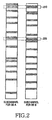
- FIG 2 is a diagram illustrating exemplary subchannels individually formed by different BSs in a general BWA communication system.
- a plurality of orthogonal frequencies for allocating one subchannel in a cell of a particular BS A, and orthogonal frequencies for allocating one subchannel in a cell of another BS B are shown in FIG. 2 .
- Shaded parts in the cell of the BS A represent a plurality of frequencies for allocating one subchannel among the total orthogonal frequencies.
- the OFDMA communication system can sequentially allocate orthogonal frequencies for one subchannel, the OFDMA communication system may generally allocates a plurality of orthogonal frequencies for one subchannel randomly or based on information reported by an MS. Therefore, even in the cell of the BS B, orthogonal frequencies form one subchannel in the same method.
- the subchannels individually formed in the cell of the BS A and the cell of the BS B are allocated to, for example, two MSs which are located in the neighboring boundaries of their respective BSs, the two MSs are allocated the same orthogonal frequencies denoted by reference numerals 210 and 220. Serious interference can occurs between the identical orthogonal frequencies 210 and 220 at which collision takes place, causing a reduction in communication quality or a possible drop of the communication.
- the hard handover causes a low SINR occurring due to the interference resulting from the identical frequencies allocated to users located in neighboring cells.
- the frequency reuse factor is set to a value greater than 1, i.e., to 3 or 7 in order to reduce the interference from the neighboring cells, it can need a special cell planning for allowing neighboring cells or sectors to use different frequencies.
- the frequency efficiency noticeably decreases, giving difficulty in installing new BSs or extending the existing BSs.
- an object of the present invention to provide a method and system for reducing a call drop rate during handover in a Broadband Wireless Access (BWA) communication system.
- BWA Broadband Wireless Access
- SINR signal-to-interference and noise ratio
- a method for providing handover in a broadband wireless access (BWA) communication system includes dividing a data transmission field for mobile stations (MSs) into a handover field and a normal user field; allocating at least one subchannel in the normal user field to non-handover MSs; allocating at least one subchannel in the handover field to handover MSs; and performing communication through the allocated subchannels.
- MSs mobile stations
- a method for providing hard handover in an orthogonal frequency division multiple access (OFDMA) communication system includes determining whether predetermined MS is located in a handover region; and if the MS is located in the handover region, allocating at least one subchannel in a handover field from among all allocable subchannels to the MS using a predetermined frequency reuse factor.
- OFDMA orthogonal frequency division multiple access
- the present invention proposes a handover method and system in a Broadband Wireless Access (BWA) communication system.
- the proposed handover method and system allocates particular fields such that a signal-to-interference and noise ratio (SINR) is improved for the users located in a cell boundary, thereby improving performance of handover.
- SINR signal-to-interference and noise ratio
- the proposed handover method and system reduces the strength of interference signals to other cells caused by a handover user, thereby supporting stable handover and increasing the entire stability of the communication system.
- an embodiment of the present invention proposes a method capable of smoothly performing handover without cell planning, and reducing a call drop rate.
- the embodiment of the present invention proposes a method for reducing an SINR with the use of a frequency reuse factor of a value greater than 1 in some of downlink and uplink data transmission fields, thereby improving communication quality and reducing interference to neighboring cells.
- Orthogonal Frequency Division Multiple Access (OFDMA) communication system
- OFDMA Orthogonal Frequency Division Multiple Access
- BWA BWA communication system
- the present invention is not limited to the OFDMA communication system, and can be applied to any communication system employing a multiple access scheme.
- the OFDMA communication system allocates resources to each user in an uplink and a downlink in units of a subchannel which is a set of particular subcarriers. There are several methods for creating the subchannel.
- a method for creating a subchannel in a downlink of, for example, an Institute of Electrical and Electronics Engineers (IEEE) 802.16 OFDMA scheme includes Partial Usage Sub-Channel (PUSC), Full Usage Sub-Channel (FUSC), optional FUSC, Adaptive Modulation and Coding (AMC) permutation subchannel allocation methods.
- PUSC Partial Usage Sub-Channel
- FUSC Full Usage Sub-Channel
- AMC Adaptive Modulation and Coding
- a method for creating a subchannel in an uplink includes PUSC, optional PUSC, and AMC permutation subchannel allocation methods.
- All of the subchannel allocation methods except for the AMC permutation subchannel allocation method basically allocate subcarriers randomly distributed over the full frequency band to one subchannel, thereby giving frequency diversity gain to each user allocated the subchannel.
- the subchannel allocation methods may divide subcarriers into a predetermined number of subcarrier groups and create a subchannel based on the subcarrier group. For example, in an IEEE 802.16 OFDMA uplink, a PUSC subcarrier allocation scheme divides the total subcarriers into tiles, each of which is includes 4 subcarriers x 3 symbols on the frequency-time axis, randomly selects the tiles, and creates a subchannel using the selected tiles. In the following description of a subchannel, the subcarriers can be replaced with subcarrier blocks.
- the method of dividing the total subcarriers into subchannels is accomplished using a formula defined according to a method of creating the subchannels.
- the formula includes a parameter set such that different subchannels are created for individual cells.
- ID cell identification
- the subchannel creating methods described above will be commonly called “distributed subcarrier allocation scheme.”
- FIG 2 an exemplary arrangement of subcarriers that constitute subchannels allocated by the distributed subcarrier allocation scheme is shown.
- Cells A and B of two base stations (BSs) have different cell IDs.
- collision occurs in two subcarriers among the subcarriers allocated to one subchannel.
- interference from a neighboring cell is determined depending on the number of collisions between subcarriers of subchannels allocated to one user and subcarriers of the total subchannels allocated in the neighboring cell. That is, in the distributed subcarrier allocation method, because subcarriers constituting a subchannel are randomly distributed over the full frequency band, collision or interference between subchannels in different cells depends on the number of allocated subchannels, on average, regardless of a particular subchannel.
- the embodiment of the present invention can adjust the amount of interference from neighboring cells by restricting the total number of allocated subchannels. An example of this will be described below.
- the system predetermines a field to be allocated to the MSs that will perform hard handover, in the total subchannels.
- M is a predetermined number according to the subchannel allocation in the embodiment of the present invention. Therefore, hard handover users in neighboring cells are allocated a common field where the distributed subcarrier allocation method is used, and adjust the total number of subchannels allocated in this field, thereby performing communication with an SINR at which stable hard handover is possible.
- FIG 3 is a diagram illustrating a format of a downlink frame in an OFDMA communication system according to an embodiment of the present invention.
- FIG 3 illustrates a method for allocating resources, for example, subchannels for hard handover users using a characteristic of the distributed subcarrier allocation scheme in a basic downlink frame for the OFDMA communication system.
- a downlink channel has a preamble field 301, a MAP information field 302, and data transmission fields 310 and 320.
- a first symbol in the downlink frame generally starts with the preamble 301. Therefore, each MS (or user) acquires synchronization of the downlink beginning at the preamble 301.
- the next several symbols of the preamble 301 transmit the MAP information 302 used for providing uplink and downlink subchannel allocation information to each MS.
- the MAP information 302 is followed by the data transmission fields 310 and 320 for data transmission.
- the data transmission fields 310 and 320 are divided into a handover field 310 for handover users and a normal user field 320 for normal users other than the handover users.
- the exemplary subchannel allocation method of FIG 3 sets up a predetermined number of, for example, X symbols in the data transmission fields 310 and 320 as the handover field 310 after the transmission of the MAP information 302, and sets up symbols after an end of the handover field 310 as the normal user field 320 to be allocated to the normal users not performing handover, other than the handover users.
- the embodiment of the present invention includes the handover field 310 for allocating particular subchannels only to the MSs located in a handover region (hereinafter referred to as handover MSs) from among all of the subchannels allocable MSs.
- the handover field 310 uses a frequency reuse factor with a value greater than 1 according to system conditions, whereas the normal user field 320 uses a frequency reuse factor with a value of 1. Therefore, resources of the normal user field 320 can create subchannels at the frequency reuse factor of 1, and are allocated to the individual MSs.
- the handover field 310 includes subchannels 311 allocated to handover MSs and subchannels 312 not-allocated to the handover MSs (i.e., allocated to non-handover MSs).
- the handover field 310 uses the distributed subcarrier allocation scheme, and only particular subchannels, for example, the subchannels 311 allocated to the handover MSs, from among all of the subchannels allocable in the handover field 310, are allocated as shown in FIG. 3 .
- the subchannels are shown adjacent to each other in FIG 3 for convenience, they are actually distributed through the distributed subcarrier allocation scheme as described above. Therefore, the individual subchannels can be allocated according to the method of FIG 2 .
- the number of symbols in the handover field 310 and a ratio of the subchannels 311 allocable to handover MSs in the handover field 310 can be statistically determined during system operation. For example, it is possible to accumulate, for a predetermined period, statistics for a ratio of the handover users and an SINR at the cell boundary, and determine a preferred value for the ratio of the subchannels allocable to handover MSs using the accumulated values.
- the downlink frame is formed such that the handover field 310 is followed by the normal user field 320, the order is subject to change.
- the objects of the present invention can be carried out if the subchannels are divided into two separate fields.
- FIG 4 is a diagram illustrating a method for allocating uplink subchannels in an OFDMA communication system according to an embodiment of the present invention.
- a method for allocating resources, for example, subchannels for hard handover users using a characteristic of the distributed subcarrier allocation scheme in a basic uplink frame for the OFDMA communication system is shown in FIG 4 .
- the uplink channel includes a control symbol field 401 for transmitting ranging symbols and Hybrid Automatic Repeat reQuest (HARQ) response signals, and data transmission fields 410 and 420 for data transmission.
- the data transmission fields 410 and 420 are divided into a normal user field 410 for normal users rather than handover users and a handover field 420 for the handover users.
- the uplink of FIG 4 can be subject to handover field setup and subchannel allocation for handover users in the method used for the downlink of FIG 3 .
- the exemplary subchannel allocation method of FIG 4 sets up particular symbols in the data transmission fields 410 and 420 following the control symbol field 410 as the normal user field 410 to be allocated to normal users not performing handover, rather than handover users, and sets up a predetermined number of, for example, X symbols after an end of the normal user field 410 as the handover field 420.
- the embodiment of the present invention includes the handover field 420 for allocating particular subchannels only to the MSs located in a handover region.
- the handover field 420 uses a frequency reuse factor having a value greater than 1, and the normal user field 410 uses a frequency reuse factor of 1.
- resources of the normal user field 410 create subchannels allocated to non-handover users at the frequency reuse factor of 1, and are allocated to the individual MSs.
- the non-handover MSs are allocated subchannels in the normal user field 410 and transmit uplink data using the allocated subchannels.
- the handover field 420 located after the normal user field 410, some (but not all) of the handover field's subchannels are used as described in connection with FIG 3 . That is, the handover field 420, as its frequency reuse factor is greater than 1, includes subchannels 421 allocated to handover MSs and subchannels 422 not-allocated to the handover MSs.
- the handover field 420 uses the distributed subcarrier allocation scheme, and only particular subchannels, for example, the subchannels 421 allocated to the handover MSs, from among all of the subchannels allocable in the handover field 420, are allocated as shown in FIG 4 .
- subchannels are shown adjacent to each other in FIG 4 for convenience, they are actually distributed using the distributed subcarrier allocation scheme as described above.
- the embodiment of the present invention allocates partial subchannels to handover MSs thereby decreasing a probability that the same frequency resources may be allocated, as a whole and the full frequency band can be used.
- FIG 5 is a block diagram schematically illustrating a structure of a BS in an OFDMA system, according to an embodiment of the present invention.
- the BS apparatus includes an upper interface 501, a data processor 503, a radio frequency (RF) processor 505, a controller 511, a memory 507, and an antenna ANT.
- RF radio frequency
- the BS includes the upper interface 501 for performing interfacing on data and control signals received from an upper network.
- the upper interface 501 is implemented with hardware logics, and its control is achieved by the controller 511.
- the upper interface 501 provides specific data received from the upper network to the data processor 503, and performs interfacing on the data to be delivered from the data processor 503 to the upper network.
- the upper interface 501 forwards a control signal delivered from the upper network to the controller 511, and forwards a control signal to be delivered from the controller 511 to the upper network, to a particular element in the upper network.
- the data processor 503 is a block for processing data to be delivered to MSs or data received from the MSs.
- the data processor 503 processes the signals according to a corresponding communication scheme, for example, OFDMA.
- the RF processor 505 up-converts transmission signals into frequency signals in a communication band available for transmission/reception between the BS and the MSs, and transmits the up-converted signals over a wireless channel via the antenna ANT.
- the RF processor 505 down-converts RF signals received from the antenna ANT into signals in a baseband available in the data processor 503.
- the controller 511 performs the overall control on the BS apparatus, and controls arrangement of symbols to be transmitted to MSs located in a handover region according to an embodiment of the present invention.
- the controller 511 1 Upon receiving a value of a ratio of subchannels allocable to handover MSs from the upper network, the controller 511 1 can update the ratio of sunchannels allocable to handover MSs.
- the controller 511 can perform a control operation of periodically delivering statistic values for the handover MSs to the upper network. If needed, the BS can be designed such that it updates a ratio of subchannels allocable to handover MSs using the statistic value.
- the BS is not identical in the ratio R to a neighboring BS, causing a region where the collision problem may occur. Therefore, it is preferable to perform the update on the ratio R of the subchannels allocable to handover MSs in the upper network.
- the memory 507 temporarily stores program data for control by the controller 511 and data generated during the control, and stores a value of a ratio of subchannels allocable to handover MSs according to an embodiment of the present invention.
- the ratio values may be differently set for individual time bands.
- the memory 507 includes a separate area for storing the statistic values.
- FIG 6 is a flowchart illustrating an operation of allocating uplink and downlink subchannels to MSs by a BS according to an embodiment of the present invention.
- a BS determines whether the corresponding MS is located in a handover region. If the MS is located in the handover region, the BS allocates subchannels in a handover field among all of the allocable subchannels to the MS using a frequency reuse factor having a value grater than 1.
- the BS checks a ratio of subchannels allocable to the MS among the subchannels in the handover field and the number of symbols (steps 602 and 604). That is, the number of symbols to be set up as the handover field and the ratio of the subchannels to allocated in the handover field to the total allocable subchannel are statistically determined during system operation.
- the BS allocates subchannels in a normal user field for non-handover MSs among the total allocable subchannels to the MS using a frequency reuse factor of 1.
- a controller 511 of a BS determines in step 600 whether it is a scheduling time for a particular MS. If it is determined in step 600 that it is a scheduling time, the controller 511 proceeds to step 602 where it checks a value of a ratio of subchannel allocable to the MS among subchannels in a handover filed shown in FIG 3 or 4 , stored in a memory 507. As described above, the value of the ratio of the allocable subchannel can be either determined spontaneously by the BS or received from an upper network. It will be assumed herein that the number of uplink/downlink symbols constituting subchannels in a handover field has a predetermined value.
- the number of uplink/downlink symbols can be either calculated spontaneously by the BS or received from the upper network.
- the number of uplink symbols constituting subchannels in the handover field may be different from the number of downlink symbols constituting subchannels in the handover field.
- the controller 511 After checking the ratio of the allocable subchannels in the handover field, the controller 511 calculates the number of symbols necessary for transmission or reception of a handover MS in step 604. That is, the controller 511 calculates the number of downlink symbols to be transmitted to the handover MS and the number of uplink symbols transmittable by the handover MS. Also, the number of symbols necessary for transmission/reception, like the ratio of the allocable subchannels, can be predetermined according to system operation.
- the embodiment of the present invention divides all cells in the same region, allocates subchannels for handover MSs using the foregoing control method, and allocates normal subchannels for non-handover MSs.
- the controller 511 determines in step 606 whether data transmission/reception is possible in the current frame. That is, the controller 511 determines whether communication between the BS and the MS through uplink/downlink is possible in the current frame using the symbols. The determination can be made by comparing a value determined depending on a value of a ratio of subchannels allocable within the number of symbols allocable in the handover field during handover of the MS in the current frame with the actual number of uplink/downlink symbols for data transmission/reception.
- the controller 511 determines that data transmission/reception is possible using the determined number of symbols. Otherwise, the controller 511 determines that the data transmission/reception (using the determined number of symbols) is impossible. That is, if it is determined in step 606 that the data transmission/reception is possible, the controller 511 proceeds to step 610. However, if it is determined in step 606 that the data transmission/reception is impossible, the controller 511 proceeds to step 608 where it selects transmission or reception symbols according to their priority.
- the BS does not change the number of symbols allocated to subchannels in the handover field every time.
- the controller 511 must transmit transmission data to a handover MS within the predetermined number of symbols. Therefore, the controller 511 determines the transmission or reception symbols taking into account MS priority or data characteristic priority, and then proceeds to step 610.
- the controller 511 can change the number of symbols allocated to subchannels in the handover field every time, the controller 511 is allowed to change the number of symbols allocated to subchannels in the handover field, required according to the number of transmission/reception symbols in the current frame.
- the controller 511 arranges transmission/reception symbols in subchannels of the handover field, and also arranges transmission/reception symbols in subchannels of a normal user field, in step 610. That is, for data transmission/reception, the controller 511 allocates subchannels in the handover field to an MS located in a handover region using a frequency reuse factor having a value greater than 1, and allocates subchannels in the normal user field to an MS located in a non-handover region using a frequency reuse factor of 1. Thereafter, the controller 511 returns to step 600 where it determines whether it is a scheduling time for the next slot.
- the present invention is not limited to this.
- the present invention can be adaptively applied to several system conditions, such as one case where a particular MS located in a handover region initiates a handover request and another case where a BS sends a handover indication to the MS located in the handover region. It is obvious to those skilled in the art that a technical structure thereof can be simply implemented through the embodiment of the present invention.
- the present invention improves an SINR for a user located in a cell boundary without separate cell planning, thereby enabling seamless handover. By doing so, it is also possible to reduce intensity of an interference signal to other cells, contributing to improvement in system stability.
Claims (8)
- Station de base, BS, permettant d'effectuer un transfert dans un système de communication à accès sans fil à large bande, BWA, comprenant :un processeur de radiofréquence, RF, (505) pour convertir de façon montante des signaux de transmission en signaux de fréquence dans une bande de communication disponible pour la transmission/réception entre la BS et des stations mobiles MS,caractérisée en ce qu'elle comprend en outre
un contrôleur (511) pour diviser un champ de transmission de données (310; 320) pour les MS en un champ de transfert (310) et un champ d'utilisateur normal (320), allouer à des MS sans transfert au moins un sous-canal (312) dans le champ d'utilisateur normal en utilisant un facteur de réutilisation de fréquence de 1, et allouer au moins à des MS de transfert un sous-canal (311) dans le champ de transfert en utilisant un facteur de réutilisation de fréquence ayant une valeur supérieure à 1. - BS selon la revendication 1, dans laquelle le contrôleur alloue aux MS de transfert au moins un sous-canal dans le champ de transfert en fonction d'un aménagement d'allocation de sous-porteuses distribuées.
- BS selon la revendication 1, dans laquelle le contrôleur alloue aux MS de transfert au moins un sous-canal prédéterminé parmi les sous-canaux dans le champ de transfert.
- BS selon la revendication 1, dans laquelle le nombre de symboles dans le champ de transfert et le rapport des sous-canaux pouvant être alloués à au moins une MS de transfert dans le champ de transfert sont déterminés de manière statistique en fonction du rapport des MS de transfert et du rapport signal sur interférences et bruit, SINR, à la limite des cellules.
- Procédé permettant d'effectuer un transfert par une station de base, BS, dans un système de communication à accès sans fil à large bande, BWA, le procédé étant caractérisé en ce qu'il comprend les étapes consistant à :diviser un champ de transmission de données pour des stations mobiles, MS, en un champ de transfert et un champ d'utilisateur normal ;allouer au moins à des MS sans transfert un sous-canal dans le champ d'utilisateur normal en utilisant un facteur de réutilisation de fréquence de 1 ;allouer au moins à des MS de transfert un sous-canal dans le champ de transfert en utilisant un facteur de réutilisation de fréquence ayant une valeur supérieure à 1 ; eteffectuer une communication par l'intermédiaire de l'au moins un sous-canal alloué.
- Procédé selon la revendication 5, dans lequel l'étape d'allocation d'un sous-canal dans le champ de transfert comporte l'allocation aux MS de transfert d'au moins un sous-canal dans le champ de transfert en fonction d'un aménagement d'allocation de sous-porteuses distribuées.
- Procédé selon la revendication 5, dans laquelle l'étape d'allocation d'un sous-canal dans le champ de transfert comporte l'allocation aux MS de transfert d'au moins un sous-canal prédéterminé parmi les sous-canaux dans le champ de transfert.
- Procédé selon la revendication 5, dans laquelle le nombre de symboles dans le champ de transfert et le rapport des sous-canaux pouvant être alloués à au moins une MS de transfert dans le champ de transfert sont déterminés de manière statistique en fonction du rapport des MS de transfert et du rapport signal sur interférences et bruit, SINR, à la limite des cellules.
Applications Claiming Priority (1)
| Application Number | Priority Date | Filing Date | Title |
|---|---|---|---|
| KR20040092692 | 2004-11-12 |
Publications (3)
| Publication Number | Publication Date |
|---|---|
| EP1657945A2 EP1657945A2 (fr) | 2006-05-17 |
| EP1657945A3 EP1657945A3 (fr) | 2012-04-11 |
| EP1657945B1 true EP1657945B1 (fr) | 2013-07-17 |
Family
ID=35836078
Family Applications (1)
| Application Number | Title | Priority Date | Filing Date |
|---|---|---|---|
| EP05024665.1A Expired - Fee Related EP1657945B1 (fr) | 2004-11-12 | 2005-11-11 | Procédé et système de transfert dans un système de communication sans fil d'accès à bande large |
Country Status (5)
| Country | Link |
|---|---|
| US (1) | US7764649B2 (fr) |
| EP (1) | EP1657945B1 (fr) |
| JP (1) | JP2006141038A (fr) |
| KR (1) | KR100703442B1 (fr) |
| CN (1) | CN100484294C (fr) |
Families Citing this family (26)
| Publication number | Priority date | Publication date | Assignee | Title |
|---|---|---|---|---|
| US8942639B2 (en) | 2005-03-15 | 2015-01-27 | Qualcomm Incorporated | Interference control in a wireless communication system |
| US8848574B2 (en) | 2005-03-15 | 2014-09-30 | Qualcomm Incorporated | Interference control in a wireless communication system |
| JP5430938B2 (ja) | 2005-10-27 | 2014-03-05 | クゥアルコム・インコーポレイテッド | 無線通信システムにおける逆方向リンク・ローディングを推定するための方法及び装置 |
| US8223703B2 (en) | 2006-05-26 | 2012-07-17 | Mitsubishi Electric Corporation | Scheduling method and communication apparatus |
| JP4935202B2 (ja) * | 2006-06-20 | 2012-05-23 | 富士通株式会社 | 通信システム |
| CN101141793B (zh) * | 2006-09-08 | 2010-12-08 | 华为技术有限公司 | 移动通信业务的切换判决方法与移动通信系统 |
| US8670777B2 (en) * | 2006-09-08 | 2014-03-11 | Qualcomm Incorporated | Method and apparatus for fast other sector interference (OSI) adjustment |
| JP5060885B2 (ja) | 2006-09-22 | 2012-10-31 | 株式会社エヌ・ティ・ティ・ドコモ | 移動通信システム及び通信制御方法 |
| EP2083578B1 (fr) * | 2006-09-22 | 2012-04-18 | Kyocera Corporation | Système de communication ofdma et procédé de communication correspondant |
| JP4459204B2 (ja) * | 2006-09-22 | 2010-04-28 | 京セラ株式会社 | Ofdma方式の通信システム及び通信方法 |
| US8699427B2 (en) | 2006-09-22 | 2014-04-15 | Kyocera Corporation | OFDMA communication system and communication method |
| US7480271B2 (en) * | 2006-09-26 | 2009-01-20 | Cisco Technology, Inc. | Method for reducing multi-cell interferences in wireless communications |
| US8095134B2 (en) * | 2006-10-27 | 2012-01-10 | Nokia Corporation | Method and apparatus for handover measurement |
| US8300596B2 (en) | 2006-10-30 | 2012-10-30 | Nokia Corporation | Apparatus, method and computer program product providing extended measurement control signal for handoff measurement under interference coordination |
| US8483038B2 (en) | 2006-12-04 | 2013-07-09 | Ntt Docomo, Inc. | Radio communication apparatus and radio communication method |
| EP2104370B1 (fr) * | 2007-01-09 | 2020-08-12 | Sun Patent Trust | Dispositif de station de base pour communications radio et procédé de mise en correspondance de signaux de commande |
| CN101296156B (zh) * | 2007-04-26 | 2011-10-19 | 王楠 | 平衡数据流无线资源分配鉴权器 |
| JP5096033B2 (ja) * | 2007-04-26 | 2012-12-12 | 京セラ株式会社 | 通信方法およびそれを利用した端末装置 |
| JP5014001B2 (ja) * | 2007-07-11 | 2012-08-29 | 三菱電機株式会社 | 基地局 |
| KR100946053B1 (ko) * | 2007-11-20 | 2010-03-09 | 삼성전기주식회사 | 광무선 기술을 기반으로 한 무선랜 시스템 및 무선랜 매체접근 제어 방법 |
| US8934855B2 (en) * | 2008-11-12 | 2015-01-13 | Apple Inc. | Antenna auto-configuration |
| KR101478246B1 (ko) * | 2008-12-09 | 2015-01-02 | 삼성전자주식회사 | 멀티 인풋 멀티 아웃풋 시스템의 하향링크 컨트롤 정보 송수신 방법 및 장치 |
| JP4965626B2 (ja) * | 2009-10-22 | 2012-07-04 | 京セラ株式会社 | Ofdma方式の通信システム及び通信方法 |
| WO2012164673A1 (fr) * | 2011-05-30 | 2012-12-06 | 富士通株式会社 | Procédé de traitement de données |
| JP5479553B2 (ja) * | 2012-09-20 | 2014-04-23 | 京セラ株式会社 | 通信方法およびそれを利用した端末装置 |
| US11064378B2 (en) * | 2015-07-16 | 2021-07-13 | Zte Wistron Telecom Ab | Measurement-based random access configuration |
Family Cites Families (18)
| Publication number | Priority date | Publication date | Assignee | Title |
|---|---|---|---|---|
| JP3110202B2 (ja) | 1993-04-21 | 2000-11-20 | 日本電気通信システム株式会社 | 周波数再利用方法 |
| US5530912A (en) | 1994-06-29 | 1996-06-25 | At&T Corp. | Traffic driven channel reservation system for handovers in cellular networks |
| US6490260B1 (en) * | 1998-08-03 | 2002-12-03 | Samsung Electronics, Co., Ltd. | Transmitter with increased traffic throughput in digital mobile telecommunication system and method for operating the same |
| JP2000278734A (ja) | 1999-03-19 | 2000-10-06 | Nec Corp | 移動通信用移動端末及び移動通信用基地局、並びに拡散符号割当方法 |
| US6947748B2 (en) * | 2000-12-15 | 2005-09-20 | Adaptix, Inc. | OFDMA with adaptive subcarrier-cluster configuration and selective loading |
| US20030039317A1 (en) * | 2001-08-21 | 2003-02-27 | Taylor Douglas Hamilton | Method and apparatus for constructing a sub-carrier map |
| KR100790114B1 (ko) * | 2002-03-16 | 2007-12-31 | 삼성전자주식회사 | 직교주파수 분할다중 접속 시스템에서 적응적 파일럿반송파 할당 방법 및 장치 |
| US7096019B2 (en) * | 2002-05-31 | 2006-08-22 | Nokia Corporation | Apparatus, and associated method, for allocating channels in a radio communication system responsive to mobile station movement |
| DE60304104T2 (de) | 2002-11-07 | 2006-11-09 | Samsung Electronics Co., Ltd., Suwon | Verfahren zur Wiederverwendung von Frequenzen in einem OFDM-Mobilfunkkommunikationssystem |
| KR100494844B1 (ko) * | 2002-12-21 | 2005-06-14 | 한국전자통신연구원 | 통신 시스템의 적응형 자원 할당 방법 |
| KR100456478B1 (ko) * | 2002-12-24 | 2004-11-09 | 한국전자통신연구원 | 직교주파수 분할다중 통신에서의 부채널 할당 방법 및 그프로그램이 저장된 기록매체 |
| US7486735B2 (en) | 2003-02-28 | 2009-02-03 | Nortel Networks Limited | Sub-carrier allocation for OFDM |
| KR100527001B1 (ko) * | 2003-04-18 | 2005-11-08 | 한국전자통신연구원 | Ofdm 시스템에서 가변적인 사이클릭 프리픽스를적용한 부반송파 할당을 통한 자원 사용 방법 |
| KR100511554B1 (ko) * | 2003-09-02 | 2005-08-31 | 한국전자통신연구원 | Ofdma fdd 기반 시스템에서의 순방향 채널 구성방법 및 순방향 채널 할당 방법 |
| US9585023B2 (en) * | 2003-10-30 | 2017-02-28 | Qualcomm Incorporated | Layered reuse for a wireless communication system |
| EP2442513A1 (fr) * | 2004-06-24 | 2012-04-18 | Nortel Networks Limited | Préambules d'un système OFDMA |
| US9294218B2 (en) * | 2004-07-16 | 2016-03-22 | Qualcomm Incorporated | Rate prediction in fractional reuse systems |
| US7796547B2 (en) * | 2004-08-06 | 2010-09-14 | Nextel Communications Inc. | Method and apparatus for providing information to mobile stations in inactive states |
-
2004
- 2004-11-19 KR KR1020040095428A patent/KR100703442B1/ko not_active IP Right Cessation
-
2005
- 2005-11-11 EP EP05024665.1A patent/EP1657945B1/fr not_active Expired - Fee Related
- 2005-11-14 US US11/273,203 patent/US7764649B2/en not_active Expired - Fee Related
- 2005-11-14 CN CN200510124644.2A patent/CN100484294C/zh not_active Expired - Fee Related
- 2005-11-14 JP JP2005329375A patent/JP2006141038A/ja active Pending
Also Published As
| Publication number | Publication date |
|---|---|
| EP1657945A3 (fr) | 2012-04-11 |
| US20060135164A1 (en) | 2006-06-22 |
| CN100484294C (zh) | 2009-04-29 |
| EP1657945A2 (fr) | 2006-05-17 |
| KR100703442B1 (ko) | 2007-04-03 |
| KR20060045305A (ko) | 2006-05-17 |
| CN1774137A (zh) | 2006-05-17 |
| US7764649B2 (en) | 2010-07-27 |
| JP2006141038A (ja) | 2006-06-01 |
Similar Documents
| Publication | Publication Date | Title |
|---|---|---|
| EP1657945B1 (fr) | Procédé et système de transfert dans un système de communication sans fil d'accès à bande large | |
| EP3094123B1 (fr) | Réutilisation de fréquence dynamique à mesure assistée dans des réseaux de télécommunication cellulaires | |
| US8483743B2 (en) | Neighboring cell interference management in SC-FDMA | |
| EP1906548B1 (fr) | Procédé et appareil pour planifier des données selon leur puissance dans un système de communication | |
| CN102577538B (zh) | 基于ul ffr的信号传输方法 | |
| EP2023559B1 (fr) | Système de communications radio | |
| TWI406524B (zh) | 於一網路中配置次頻道之系統及方法 | |
| US8249609B2 (en) | Radio resource allocation method and radio station | |
| US20070086474A1 (en) | Method for estimating a map size in a wireless mobile communication system | |
| EP2351448B1 (fr) | Reutilisation fractionnee de frequences en ofdma | |
| KR20050117445A (ko) | 직교 주파수 분할 다중 접속 방식의 무선 통신 시스템에서핸드오버 방법 | |
| KR20070098283A (ko) | 통신 시스템에서 자원 할당 방법 및 시스템 | |
| CN102084676A (zh) | 用于无线通信的具有改进的资源粒度的置换设备和方法 | |
| US8374211B2 (en) | Method for data transmission and communication system | |
| JP5517660B2 (ja) | 広帯域無線通信システムにおけるマップのサイズ推定装置及び方法 | |
| US8190106B2 (en) | Base station control apparatus and base station control method | |
| EP1944987B1 (fr) | Procédé d'attribution de ressources radio dans des réseaux de communication à cellules multiples, une station de base et un réseau de communication à cellules multiples correspondant | |
| KR20070017272A (ko) | 광대역 무선 접속 통신 시스템에서 하향링크 자원 할당방법 | |
| KR20060056141A (ko) | 직교 주파수 다중 접속 방식의 무선 통신 시스템에서자원할당 방법 및 시스템 | |
| KR20060056210A (ko) | 직교 주파수 분할 다중 접속 통신 시스템에서 핸드오버서비스 방법 | |
| KR20060056168A (ko) | 직교 주파수 다중 접속 방식의 무선 통신 시스템에서 전력제어 방법 및 장치 |
Legal Events
| Date | Code | Title | Description |
|---|---|---|---|
| PUAI | Public reference made under article 153(3) epc to a published international application that has entered the european phase |
Free format text: ORIGINAL CODE: 0009012 |
|
| 17P | Request for examination filed |
Effective date: 20051111 |
|
| AK | Designated contracting states |
Kind code of ref document: A2 Designated state(s): AT BE BG CH CY CZ DE DK EE ES FI FR GB GR HU IE IS IT LI LT LU LV MC NL PL PT RO SE SI SK TR |
|
| AX | Request for extension of the european patent |
Extension state: AL BA HR MK YU |
|
| REG | Reference to a national code |
Ref country code: DE Ref legal event code: R079 Ref document number: 602005040400 Country of ref document: DE Free format text: PREVIOUS MAIN CLASS: H04Q0007380000 Ipc: H04W0072040000 |
|
| PUAL | Search report despatched |
Free format text: ORIGINAL CODE: 0009013 |
|
| AK | Designated contracting states |
Kind code of ref document: A3 Designated state(s): AT BE BG CH CY CZ DE DK EE ES FI FR GB GR HU IE IS IT LI LT LU LV MC NL PL PT RO SE SI SK TR |
|
| AX | Request for extension of the european patent |
Extension state: AL BA HR MK YU |
|
| RIC1 | Information provided on ipc code assigned before grant |
Ipc: H04W 72/04 20090101AFI20120305BHEP |
|
| RAP1 | Party data changed (applicant data changed or rights of an application transferred) |
Owner name: SAMSUNG ELECTRONICS CO., LTD. |
|
| AKX | Designation fees paid |
Designated state(s): DE FR GB IT SE |
|
| GRAP | Despatch of communication of intention to grant a patent |
Free format text: ORIGINAL CODE: EPIDOSNIGR1 |
|
| GRAS | Grant fee paid |
Free format text: ORIGINAL CODE: EPIDOSNIGR3 |
|
| GRAA | (expected) grant |
Free format text: ORIGINAL CODE: 0009210 |
|
| AK | Designated contracting states |
Kind code of ref document: B1 Designated state(s): DE FR GB IT SE |
|
| REG | Reference to a national code |
Ref country code: GB Ref legal event code: FG4D |
|
| REG | Reference to a national code |
Ref country code: DE Ref legal event code: R096 Ref document number: 602005040400 Country of ref document: DE Effective date: 20130912 |
|
| REG | Reference to a national code |
Ref country code: SE Ref legal event code: TRGR |
|
| PLBE | No opposition filed within time limit |
Free format text: ORIGINAL CODE: 0009261 |
|
| STAA | Information on the status of an ep patent application or granted ep patent |
Free format text: STATUS: NO OPPOSITION FILED WITHIN TIME LIMIT |
|
| 26N | No opposition filed |
Effective date: 20140422 |
|
| REG | Reference to a national code |
Ref country code: DE Ref legal event code: R097 Ref document number: 602005040400 Country of ref document: DE Effective date: 20140422 |
|
| REG | Reference to a national code |
Ref country code: FR Ref legal event code: PLFP Year of fee payment: 12 |
|
| REG | Reference to a national code |
Ref country code: FR Ref legal event code: PLFP Year of fee payment: 13 |
|
| REG | Reference to a national code |
Ref country code: FR Ref legal event code: PLFP Year of fee payment: 14 |
|
| PGFP | Annual fee paid to national office [announced via postgrant information from national office to epo] |
Ref country code: DE Payment date: 20181022 Year of fee payment: 14 Ref country code: SE Payment date: 20181023 Year of fee payment: 14 |
|
| PGFP | Annual fee paid to national office [announced via postgrant information from national office to epo] |
Ref country code: GB Payment date: 20181023 Year of fee payment: 14 Ref country code: IT Payment date: 20181113 Year of fee payment: 14 Ref country code: FR Payment date: 20181029 Year of fee payment: 14 |
|
| REG | Reference to a national code |
Ref country code: DE Ref legal event code: R119 Ref document number: 602005040400 Country of ref document: DE |
|
| REG | Reference to a national code |
Ref country code: SE Ref legal event code: EUG |
|
| PG25 | Lapsed in a contracting state [announced via postgrant information from national office to epo] |
Ref country code: SE Free format text: LAPSE BECAUSE OF NON-PAYMENT OF DUE FEES Effective date: 20191112 |
|
| GBPC | Gb: european patent ceased through non-payment of renewal fee |
Effective date: 20191111 |
|
| PG25 | Lapsed in a contracting state [announced via postgrant information from national office to epo] |
Ref country code: IT Free format text: LAPSE BECAUSE OF NON-PAYMENT OF DUE FEES Effective date: 20191111 Ref country code: GB Free format text: LAPSE BECAUSE OF NON-PAYMENT OF DUE FEES Effective date: 20191111 Ref country code: DE Free format text: LAPSE BECAUSE OF NON-PAYMENT OF DUE FEES Effective date: 20200603 Ref country code: FR Free format text: LAPSE BECAUSE OF NON-PAYMENT OF DUE FEES Effective date: 20191130 |