EP1906548B1 - Procédé et appareil pour planifier des données selon leur puissance dans un système de communication - Google Patents
Procédé et appareil pour planifier des données selon leur puissance dans un système de communication Download PDFInfo
- Publication number
- EP1906548B1 EP1906548B1 EP20070117146 EP07117146A EP1906548B1 EP 1906548 B1 EP1906548 B1 EP 1906548B1 EP 20070117146 EP20070117146 EP 20070117146 EP 07117146 A EP07117146 A EP 07117146A EP 1906548 B1 EP1906548 B1 EP 1906548B1
- Authority
- EP
- European Patent Office
- Prior art keywords
- region
- data burst
- pdu
- slots
- burst
- Prior art date
- Legal status (The legal status is an assumption and is not a legal conclusion. Google has not performed a legal analysis and makes no representation as to the accuracy of the status listed.)
- Expired - Fee Related
Links
Images


Classifications
-
- H—ELECTRICITY
- H04—ELECTRIC COMMUNICATION TECHNIQUE
- H04B—TRANSMISSION
- H04B7/00—Radio transmission systems, i.e. using radiation field
- H04B7/005—Control of transmission; Equalising
-
- H—ELECTRICITY
- H04—ELECTRIC COMMUNICATION TECHNIQUE
- H04W—WIRELESS COMMUNICATION NETWORKS
- H04W52/00—Power management, e.g. TPC [Transmission Power Control], power saving or power classes
- H04W52/04—TPC
- H04W52/18—TPC being performed according to specific parameters
- H04W52/28—TPC being performed according to specific parameters using user profile, e.g. mobile speed, priority or network state, e.g. standby, idle or non transmission
-
- H—ELECTRICITY
- H04—ELECTRIC COMMUNICATION TECHNIQUE
- H04B—TRANSMISSION
- H04B7/00—Radio transmission systems, i.e. using radiation field
- H04B7/02—Diversity systems; Multi-antenna system, i.e. transmission or reception using multiple antennas
-
- H—ELECTRICITY
- H04—ELECTRIC COMMUNICATION TECHNIQUE
- H04L—TRANSMISSION OF DIGITAL INFORMATION, e.g. TELEGRAPHIC COMMUNICATION
- H04L65/00—Network arrangements, protocols or services for supporting real-time applications in data packet communication
-
- H—ELECTRICITY
- H04—ELECTRIC COMMUNICATION TECHNIQUE
- H04L—TRANSMISSION OF DIGITAL INFORMATION, e.g. TELEGRAPHIC COMMUNICATION
- H04L65/00—Network arrangements, protocols or services for supporting real-time applications in data packet communication
- H04L65/40—Support for services or applications
-
- H—ELECTRICITY
- H04—ELECTRIC COMMUNICATION TECHNIQUE
- H04W—WIRELESS COMMUNICATION NETWORKS
- H04W52/00—Power management, e.g. TPC [Transmission Power Control], power saving or power classes
- H04W52/04—TPC
- H04W52/30—TPC using constraints in the total amount of available transmission power
- H04W52/34—TPC management, i.e. sharing limited amount of power among users or channels or data types, e.g. cell loading
-
- H—ELECTRICITY
- H04—ELECTRIC COMMUNICATION TECHNIQUE
- H04W—WIRELESS COMMUNICATION NETWORKS
- H04W52/00—Power management, e.g. TPC [Transmission Power Control], power saving or power classes
- H04W52/04—TPC
- H04W52/18—TPC being performed according to specific parameters
- H04W52/24—TPC being performed according to specific parameters using SIR [Signal to Interference Ratio] or other wireless path parameters
- H04W52/241—TPC being performed according to specific parameters using SIR [Signal to Interference Ratio] or other wireless path parameters taking into account channel quality metrics, e.g. SIR, SNR, CIR, Eb/lo
-
- H—ELECTRICITY
- H04—ELECTRIC COMMUNICATION TECHNIQUE
- H04W—WIRELESS COMMUNICATION NETWORKS
- H04W52/00—Power management, e.g. TPC [Transmission Power Control], power saving or power classes
- H04W52/04—TPC
- H04W52/18—TPC being performed according to specific parameters
- H04W52/28—TPC being performed according to specific parameters using user profile, e.g. mobile speed, priority or network state, e.g. standby, idle or non transmission
- H04W52/281—TPC being performed according to specific parameters using user profile, e.g. mobile speed, priority or network state, e.g. standby, idle or non transmission taking into account user or data type priority
-
- H—ELECTRICITY
- H04—ELECTRIC COMMUNICATION TECHNIQUE
- H04W—WIRELESS COMMUNICATION NETWORKS
- H04W52/00—Power management, e.g. TPC [Transmission Power Control], power saving or power classes
- H04W52/04—TPC
- H04W52/18—TPC being performed according to specific parameters
- H04W52/28—TPC being performed according to specific parameters using user profile, e.g. mobile speed, priority or network state, e.g. standby, idle or non transmission
- H04W52/286—TPC being performed according to specific parameters using user profile, e.g. mobile speed, priority or network state, e.g. standby, idle or non transmission during data packet transmission, e.g. high speed packet access [HSPA]
-
- H—ELECTRICITY
- H04—ELECTRIC COMMUNICATION TECHNIQUE
- H04W—WIRELESS COMMUNICATION NETWORKS
- H04W52/00—Power management, e.g. TPC [Transmission Power Control], power saving or power classes
- H04W52/04—TPC
- H04W52/30—TPC using constraints in the total amount of available transmission power
- H04W52/34—TPC management, i.e. sharing limited amount of power among users or channels or data types, e.g. cell loading
- H04W52/343—TPC management, i.e. sharing limited amount of power among users or channels or data types, e.g. cell loading taking into account loading or congestion level
-
- H—ELECTRICITY
- H04—ELECTRIC COMMUNICATION TECHNIQUE
- H04W—WIRELESS COMMUNICATION NETWORKS
- H04W52/00—Power management, e.g. TPC [Transmission Power Control], power saving or power classes
- H04W52/04—TPC
- H04W52/30—TPC using constraints in the total amount of available transmission power
- H04W52/34—TPC management, i.e. sharing limited amount of power among users or channels or data types, e.g. cell loading
- H04W52/346—TPC management, i.e. sharing limited amount of power among users or channels or data types, e.g. cell loading distributing total power among users or channels
Definitions
- the present invention relates generally to a method and apparatus for scheduling data considering power of the data in a communication system.
- Intensive research on the 4 th Generation (4G) communication system, or the next generation communication system, is being conducted to provide to users services having various Quality of Service (QoS) classes at a data rate of about 100 Mbps.
- QoS Quality of Service
- active research into the 4G communication system is being conducted to support high-speed services by guaranteeing mobility and QoS for a Broadband Wireless Access (BWA) communication system such as a wireless Local Area Network (LAN) system and a wireless Metropolitan Area Network (MAN) system, and an Institute of Electrical and Electronics Engineers (IEEE) 802.16 communication system is a typical BWA communication system.
- BWA Broadband Wireless Access
- LAN wireless Local Area Network
- MAN wireless Metropolitan Area Network
- IEEE Institute of Electrical and Electronics Engineers 802.16 communication system
- the IEEE 802.16 communication system employs Orthogonal Frequency Division Multiplexing (OFDM)/Orthogonal Frequency Division Multiple Access (OFDMA) to support broadband transmission networks for physical channel of the wireless MAN system.
- OFDM/OFDMA can transmit multiple subcarriers with orthogonality being kept therebetween, thereby obtaining the optimal transmission efficiency during fast data transmission.
- OFDM/OFDMA as it is high in frequency efficiency and robust against multi-path fading, can obtain the optimal transmission efficiency during fast data transmission.
- OFDM/OFDMA as it uses frequency spectra in an overlapping manner, is high in frequency efficiency, is robust against frequency selective fading and multi-path fading, can reduce Inter-Symbol Interference (ISI) using a guard interval, and can be designed with an equalizer having a simple hardware structure.
- the communication system employing OFDM/OFDMA can include Wireless Broadband Internet (WiBro), or 2.3-GHz band Portable Internet Service.
- the communication system employing OFDMA should appropriately distribute resources to increase channel utilization between multiple Mobile Stations (MSs), located in one cell, and a Base Station (BS).
- a subcarrier is one of the sharable resources in the communication system employing OFDMA, and the subcarriers are channelized. The optimal channel utilization is guaranteed depending on how the subcarriers are assigned to the MSs in the cell using a predetermined scheme.
- a set of at least one subcarrier will be referred to as a subchannel.
- Data transmission of the BWA communication system is achieved on a frame-by-frame basis, and each frame is divided into an interval capable of transmitting downlink data and an interval capable of transmitting uplink data.
- the uplink/downlink data intervals each are divided again into the frequency axis and the time axis.
- Each element formed in a two-dimensional arrangement of the frequency axis and the time axis is called a 'slot'.
- the BS uses MAPs defined as normal MAPs or new normal MAPs (also known as Hybrid Automatic Repeat reQuest (H-ARQ) MAPs).
- the data bursts are assigned in the downlink data interval over multiple time slots.
- the BS performs power boosting or power deboosting on the assigned data bursts, thereby increasing the downlink resource utilization.
- the power boosting/deboosting levels are defined as -12, -9, -6, -3, 0, 3, 6, 9, 12 dB.
- US 2003/0185214 A1 relates to a method for scheduling and transmitting protocol data units (PDUs) by scheduling and selectively transmitting the PDUs in a downlink direction in a code division multiple access (CDMA) wireless communication system.
- a system and method for classifying the PDUs by the PCPS (Power-strength Classified Packet Scheduling) scheme is provided.
- a scheduling unit is provided comprising a bandwidth adjuster, a time-based scheduler, and a power-based scheduler.
- the bandwidth adjuster classifies the PS-classes according to each position of mobile communication devices and the connection power of base stations in the communication-covered range of the wireless communication system.
- the bandwidth adjuster also allows the corresponding bandwidth ratio according to a plurality of PS-classes and different qualities of service.
- the bandwidth adjuster is used for classifying the Power-Strength (PS) -classes in the communication-covered range of the wireless communication system according to the power of the communication session transmitted to the based station by wireless communication devices.
- the bandwidth adjuster allots the corresponding bandwidth ratios to different PS-classes according to the sum of the service rate of the communication session.
- the bandwidth adjuster assigns the priority of the PS-classes according to the desired quality of service of the communication sessions to retain the bandwidth resources.
- the highest priority of different PS-classes is scheduled in the predetermined time frame. In other words, the bandwidth adjuster chooses only one predetermined time frame entering into the time-based scheduler. There are two levels for scheduling the PDUs to be scheduled in the temporary queue.
- First is based on the priority of the PS-classes in each predetermined time frame.
- Second is based in the priority values in the same PS-class.
- the minimum signal-to-interference ratio (minSIR) and the target-SIR must be previously provided to the power-based scheduler for scheduling.
- the minSIR means the minimum required power-strength for the PDU when the base station communicates with the mobile communications devices in the communication session.
- the minSIR is predetermined by the base station.
- the target-SIR is determined by the data error rate received by the mobile communication devices.
- the power-based scheduler sends back sequentially to the time-based scheduler the PDUs whose power amounts to the exceeding of the maximum power-strength of the wireless communication system according to the corresponding priority values of the PDUs in an order from small to large so that the wireless communication system transmits all the remaining PDUs whose total power being within the maximum power-strength at a time.
- the time-based scheduler raises priority values for the returned PDUs from the power-based scheduler, and schedules those PDUs together with the PDUs to be scheduled received in the next predetermined time frame.
- the conventional technology has presented no detailed scheme capable of assigning the data bursts in the frame, and the conventional BS downlink resource assignment assigns resources in the rectangular shape simply in QoS priority order without considering the size of the bursts and the number of null-padded slots, thereby causing a waste of the slots.
- an aspect of the present invention is to address at least the problems and/or disadvantages discussed above and to provide at least the advantages described below. Accordingly, an aspect of the present invention is to provide a downlink resource assignment method for minimizing the number of slots wasted during BS downlink resource assignment, and improving the cell coverage area or cell capacity by boosting power of bursts to be assigned to an edge cell user whose Carrier-to-Interference Noise Ratio (CINR) is less than a first threshold for separating a boosting region from a normal region, and deboosting power of bursts to be assigned to a near cell user whose CINR is greater than a second threshold for separating the normal region from a deboosting region.
- CINR Carrier-to-Interference Noise Ratio
- Another aspect of the present invention is to provide a downlink resource assignment method capable of reducing its implementation complexity.
- a method for scheduling data in a communication system having a downlink frame structure including power control regions of a boosting region for 3dB boosting power of a data burst, a normal region for keeping power of the data burst, and a deboosting region for -3dB deboosting power of the data burst.
- the data scheduling method includes comparing a Carrier-to-Interference Noise Ratio (CINR) of a first data burst to be transmitted to a Mobile Station (MS) with a predetermined threshold to determine a first region indicative of a power control region of the first data burst; checking a power control region of a first Packet Data Unit (PDU) indicative of a PDU with a minimum Quality of Service (QoS) priority, among PDUs constituting the first data burst, if a minimum total number of subchannels necessary for transmitting a total number of slots for transmission of the first data burst that underwent power control for the first region, is greater than or equal to a predetermined maximum number of subchannels per symbol; determining a minimum number Fo of subchannels of the first data burst in a second region such that Fo is less than or equal to the maximum number of subchannels per symbol, considering a minimum number of subchannels of remaining power control regions except for the second region indicative of the checked power control region of the first PDU
- a system for scheduling data in a communication system having a downlink frame structure including power control regions of a boosting region for 3dB boosting power of a data burst, a normal region for keeping power of the data burst, and a deboosting region for -3dB deboosting power of the data burst.
- the data scheduling system includes a Base Station (BS) for comparing a Carrier-to-Interference Noise Ratio (CINR) of a first data burst to be transmitted to a Mobile Station (MS) with a predetermined threshold to determine a first region indicative of a power control region of the first data burst; checking a power control region of a first Packet Data Unit (PDU) indicative of a PDU with a minimum Quality of Service (QoS) priority, among PDUs constituting the first data burst, if a minimum total number of subchannels necessary for transmitting a total number of slots for transmission of the first data burst that underwent power control for the first region, is greater than or equal to a predetermined maximum number of subchannels per symbol; determining a minimum number Fo of subchannels of the first data burst in a second region such that Fo is less than or equal to the maximum number of subchannels per symbol, considering a minimum number of subchannels of remaining power control regions except for the second region indicative of the checked
- the present invention provides a method and system for assigning resources in a communication system, for example, an Institute of Electrical and Electronics Engineers (IEEE) 802.16e communication system, or a Broadband Wireless Access (BWA) communication system.
- IEEE Institute of Electrical and Electronics Engineers
- BWA Broadband Wireless Access
- OFDM Orthogonal Frequency Division Multiplexing
- OFDMA Orthogonal Frequency Division Multiple Access
- the resource assignment method and system provided by the present invention can be applied to other communication systems.
- the present invention provides a resource assignment method and system for data transmission between a transmitter, or a Base Station (BS), in charge of the cell, and a receiver, or a Mobile Station (MS), receiving a communication service from the transmitter in the communication system.
- BS Base Station
- MS Mobile Station
- the BS transmits resource assignment information to the MSs over a MAP message.
- a MAP message used for transmitting downlink resource assignment information is referred to as a DownLink-MAP (DL-MAP) message
- a MAP message used for transmitting uplink resource assignment information is referred to as a UpLink-MAP (UL-MAP) message.
- DL-MAP DownLink-MAP
- UL-MAP UpLink-MAP
- the MSs can each detect positions of resources assigned thereto and control information of the data that they should receive, by decoding the DL-MAP message and the UL-MAP message transmitted by the BS. By detecting the resource assignment positions and control information, the MSs can receive/transmit data over the downlink and uplink.
- data transmission/reception is performed on a frame-by-frame basis, and the frame is divided into a region for transmitting downlink data, and a region for transmitting uplink data.
- the regions for transmitting the data are formed in a two-dimensional arrangement of 'frequency domain' x 'time domain', and each element in the two-dimensional arrangement is defined as a slot, which is an assignment unit. That is, the frequency domain is divided into subchannels, each of which is a bundle of subcarriers, and the time domain is divided into symbols.
- the slot indicates a region in which one subchannel occupies the symbols.
- Each slot is assigned to only one arbitrary MS among the MSs located in one sector, and a set of slots assigned to the MSs located in one sector is a burst.
- FIG. 1 illustrates a downlink frame structure of a BWA communication system according to an embodiment of the present invention.
- a downlink frame is divided into a preamble region 102, a MAP region 104, and a data burst assignment region 106.
- a preamble for synchronization acquisition is disposed in the preamble region 102, and the MAP region 104 includes a DL-MAP and a UL-MAP, each of which includes broadcast data information that the MSs commonly receive.
- the data burst assignment region 106 is divided into a boosting region 108, in which downlink data bursts transmitted to MSs are assigned, for performing 3dB power boosting on the bursts belonging to the corresponding region, a normal region 110 for performing no power boosting on the bursts belonging to the corresponding region, and a deboosting region 112 for performing -3dB power boosting on the bursts belonging to the corresponding region. Thresholds used for assigning corresponding bursts to the boosting region, the normal region and the deboosting region in a distributed manner follow the criterion defined by an upper scheduler.
- CINR Carrier-to-Interference Noise Ratio
- first threshold for separating the boosting region 108 from the normal region 110
- second threshold for separating the normal region 110 from the deboosting region 112
- power of the bursts to be assigned thereto is assigned to the deboosting region 112.
- the position and assignment-relation information of the downlink data bursts is included in the DL-MAP of the MAP region 104.
- the data burst assignment region 106 is divided along the horizontal time axis and the vertical frequency axis.
- the number of subchannels, indicating the optimal performance, for the case where Full Usage of Sub Channel (FUSC) and Partial Usage of Sub Channel (PUSC) are used in the divided regions, will now be determined.
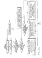
- FIG. 2 illustrates a resource assignment procedure according to an embodiment of the present invention.
- a BS performs queue scheduling for determining the priority of each individual connection for the data bursts that the BS will transmit separately for each service class.
- the data burst can be divided into an integer number of slots, and when the BS performs two-dimensional assignment of frequency and time on the data burst, consideration should be taken so that there is no slot wasted in the downlink frame.
- the downlink frame is divided along the frequency axis and the symbol axis (time axis), and has several slots that take both the frequency and the time into consideration.
- the BS performs region assignment for assigning, to a boosting region, power of bursts to be assigned to an edge cell user whose measured CINR is less than the first threshold, assigning, to a normal region, power of bursts to be assigned to a normal cell user whose CINR is greater than the first threshold and less than the second threshold, and assigning, to a deboosting region, power of bursts to be assigned to a near cell user whose CINR is greater than the second threshold,.
- the BS determines a MAP size by estimating MAP overhead necessary for data bursts to be transmitted,.
- the MAP size should be set to a large value when there are many data bursts to be transmitted.
- the increase in the MAP size reduces the data burst region size. Therefore, the MAP size and the data burst region size should be properly determined on a trade-off basis.
- the BS performs data burst concatenation for configuring one burst using the data bursts being transmitted to the same MS, or the data bursts having the same Modulation and Coding Scheme (MCS) level, to minimize the MAP overhead.
- MCS Modulation and Coding Scheme
- the MCS are various combinations of modulation schemes and coding schemes, and multiple MCSs with level 1 to level N can be defined according to the number of MCSs.
- step 210 the BS assigns data bursts received in transmission priority order, in the data burst region of the downlink frame according to a predetermined rule.
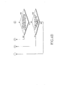
- FIGs. 3A to 3C illustrate a burst assignment procedure of a BS, in which power boosting/deboosting is taken into consideration, according to an embodiment of the present invention.
- Table 1 shows parameters for a WiBro downlink burst assignment algorithm that considers power boosting.
- Table 1 Description N Total number of slots that should be transmitted (Total Slot) N(boost) Total number of slots to be assigned to boosting region N(normal) Total number of slots to be assigned to normal region N(deboost) Total number of slots to be assigned to deboosting region Effective Power N(boost) 'Total number of slots to be assigned to boosting region' * 2 Effective Power N(normal) 'Total number of slots to be assigned to normal region' * 1 Effective Power N(deboost) 'Total number of slots to be assigned to deboosting region' * 0.5 No(boost) Maximum number of slots transmittable in boosting region of DL subframe determined through MAP size estimation No(normal) subframe Maximum number of slots transmittable in normal region of DL determined through MAP size estimation No(deboost) DL Maximum number of slots transmittable in deboosting region of subframe determined through MAP size
- the BS determines a MAP size by estimating MAP overhead necessary for data bursts to be transmitted.
- the MAP size should be set to a large value when there are many data bursts to be transmitted.
- the increase in the MAP size reduces the data burst region size. Therefore, the MAP size and the data burst region size should be properly determined on a trade-off basis.
- the BS calculates N (total number of slots that should be transmitted), So (number of initial data symbols), No (maximum number of slots transmittable in DL subframe determined through MAP size estimation), and the number of DL MAP Information Elements (IEs).
- N total number of slots that should be transmitted
- So number of initial data symbols
- No maximum number of slots transmittable in DL subframe determined through MAP size estimation
- IEs DL MAP Information Elements
- the BS performs, on each corresponding region, burst concatenation for configuring one burst using the data bursts being transmitted to the same MS, or the Packet Data Units (PDUs) having the same Modulation and Coding Scheme (MCS) level, to minimize the MAP overhead, and then proceeds to step 306.
- the BS adjusts QoS priorities disordered due to the concatenation, and calculates size priorities to be used in the burst assignment algorithm.
- the MCS are various combinations of modulation schemes and coding schemes, and multiple MCSs with level 1 to level N can be defined according to the number of MCSs.
- the BS compares Fo(total) with the maximum number of subchannels per symbol, and compares Effective Power Fo(total) with the maximum number of subchannels per symbol.
- the Fo(total) is a sum of Fo(boost), Fo(normal) and Fo(deboost)
- the Effective Power Fo(total) is a sum of Effective Power Fo(boost), Effective Power Fo(normal) and Effective Power Fo(deboost).
- the BS proceeds to step 308.
- the Fo(total) or Effective Power Fo(total) is less than the maximum number of subchannels per symbol, the BS proceeds to step 312.
- the BS determines if a PDU with the minimum QoS priority (hereinafter referred to as a 'minimum-QoS priority PDU') belongs to a boosting region, and if the minimum-QoS priority PDU belongs to the boosting region, the BS proceeds to step 314. However, if the minimum-QoS priority PDU does not belong to the boosting region, the BS proceeds to step 310 where it determines if the minimum-QoS priority PDU belongs to a normal region. If it is determined that the minimum-QoS priority PDU belongs to the normal region, the BS proceeds to step 316, and if the minimum-QoS priority PDU does not belong to the normal region, the BS proceeds to step 318.
- a PDU with the minimum QoS priority hereinafter referred to as a 'minimum-QoS priority PDU'
- the BS calculates Fo(region), No(region) and Ro(region) of the corresponding regions using Equation (1), and then proceeds to step 320 (A).
- the BS calculates Fo, No and Ro of all regions.
- the BS calculates Fo, No and Ro of all regions.
- the Fo, No and Ro of the region to which the minimum-QoS priority PDU belongs are determined in a relative manner such that they should not exceed the maximum number of transmittable subchannels per symbol according to the Fo determined in other regions except for the region to which the minimum-QoS priority PDU belongs.
- the BS calculates Fo of the region not including the minimum-QoS priority PDU as ceil(N/So). However, because the minimum-QoS priority PDU undergoes fragmentation, Fo of the region including the minimum-QoS priority PDU is determined as a minimum value using Equation (2) such that it should not exceed the maximum number of transmittable subchannels per symbol according to the Fo determined in other regions except for the region to which the minimum-QoS priority PDU belongs.
- step 320 the BS calculates Fu(region) and Su(region) of the corresponding regions using Equation (3), and then proceeds to step 322.
- step 322 the BS assigns bursts in descending order of the size, and then proceeds to step 324 where the BS determines if there is any burst to be assigned and if there is any remaining slot. If there is any burst to be assigned and there is any remaining slot, the BS proceeds to step 326 (B). However, if there is no burst to be assigned or if there is no remaining slot, the BS ends the burst assignment.
- the BS determines if the burst to be assigned belongs to the boosting region. If the burst to be assigned does not belong to the boosting region, the BS proceeds to step 328, and if the burst to be assigned belongs to the boosting region, the BS proceeds to step 330 where it uses Fu(boost) and Su(boost) of the assignable boosting region.
- the BS assigns the burst to be assigned in the increasing direction of the subchannel axis using the full Su(boost), or assigns the burst to be assigned in the increasing direction of the symbol axis using the full Fu(boost), and then proceeds to step 332 where the BS calculates Ru(boost), Fu(boost) and Su(boost), and then proceeds to step 342.
- the BS determines if the burst to be assigned belongs to the normal region. If the burst to be assigned belongs to the normal region, the BS proceeds to step 334, and if the burst to be assigned does not belong to the normal region, the BS proceeds to step 338.
- step 334 the BS uses Fu(normal) and Su(normal) of the assignable normal region. That is, to minimize the number of null-padded slots, the BS assigns the burst in the increasing direction of the subchannel axis using the full Su(normal), or assigns the burst in the increasing direction of the symbol axis using the full Fu(normal), and then proceeds to step 336 where it calculates Ru(normal), Fu(normal) and Su(normal), and then proceeds to step 342.
- step 338 the BS uses (Fu(deboost) and Su(deboost) of the assignable deboosting region.
- the BS assigns the burst in the increasing direction of the subchannel axis using the full Su(deboost), or assigns the burst in the increasing direction of the symbol axis using the full Fu(deboost), and then proceeds to step 340 where it calculates Ru(deboost), Fu(deboost) and Su(deboost), and then proceeds to step 342.
- step 342 the BS compares Ru(region) with Ro(region) of the corresponding regions in size. If the Ru(region) is less than or equal to the Ro(region) calculated in steps 312 to 318, the BS returns to step 322(D), and if the Ru(region) is greater than the Ro(region) calculated in steps 312 to 318, the BS proceeds to step 344.
- the BS compares the Fo(total) with the maximum number of subchannels per symbol.
- the Fo(total) is a sum of Fo(boost), Fo(normal) and Fo(deboost).
- the BS increases in step 346 the Fo(region) of the region in which the Ru(region) is greater than the Ro(region), by 'Fo(region) + 1', i.e. 1, and then returns to step 322(D).
- the BS removes one minimum-QoS priority PDU in step 348, and then returns to step 302(C). Thereafter, in step 302, the BS does not include the PDU with the next QoS priority of the removed minimum QoS priority in calculating the N.
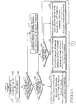
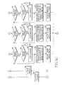
- FIGs. 4A to 4D illustrate a BS's burst assignment procedure including burst fragmentation, in which power boosting/deboosting is taken into consideration, according to an embodiment of the present invention.
- the BS determines a MAP size by estimating MAP overhead necessary for data bursts to be transmitted, and then proceeds to step 404.
- the MAP size should be set to a large value when there are many data bursts to be transmitted.
- the increase in the MAP size reduces the data burst region size. Therefore, the MAP size and the data burst region size should be properly determined on a trade-off basis.
- the BS calculates N (total number of slots that should be transmitted), So (number of initial data symbols), No (maximum number of slots transmittable in DL subframe determined through MAP size estimation), and the number of DL MAP IEs.
- the BS performs, on each corresponding region, burst concatenation for configuring one burst using the data bursts being transmitted to the same MS, or the PDUs having the same MCS level, to minimize the MAP overhead. Specifically, the BS adjusts QoS priorities disordered due to the concatenation, and calculates size priorities to be used in the burst assignment algorithm.
- the MCS are various combinations of modulation schemes and coding schemes, and multiple MCSs with level 1 to level N can be defined according to the number of MCSs.
- the BS compares Fo(total) with the maximum number of subchannels per symbol, and compares Effective Power Fo(total) with the maximum number of subchannels per symbol.
- the Fo(total) is a sum of Fo(boost), Fo(normal) and Fo(deboost)
- the Effective Power Fo(total) is a sum of Effective Power Fo(boost), Effective Power Fo(normal) and Effective Power Fo(deboost). If the Fo(total) or Effective Power Fo(total) is greater than or equal to the maximum number of subchannels per symbol, the BS proceeds to step 408. However, if the Fo(total) or Effective Power Fo(total) is less than the maximum number of subchannels per symbol, the BS proceeds to step 412.
- step 408 the BS determines if the minimum-QoS priority PDU belongs to a boosting region. As a result of the check, if the minimum-QoS priority PDU belongs to the boosting region, the BS proceeds to step 414. However, if the minimum-QoS priority PDU does not belong to the boosting region, the BS proceeds to step 410 where it determines if the minimum-QoS priority PDU belongs to a normal region. If it is determined that the minimum-QoS priority PDU belongs to the normal region, the BS proceeds to step 416, and if the minimum-QoS priority PDU does not belong to the normal region, the BS proceeds to step 418.
- the BS calculates Fo(region), No(region) and Ro(region) of all regions using Equation (1), and then proceeds to step 420 (A).
- the BS calculates Fo of other regions not including the minimum-QoS priority PDU as ceil(N/So). However, because the minimum-QoS priority PDU undergoes fragmentation, Fo of the region including the minimum-QoS priority PDU is determined as the minimum value using Equation (2) such that it should not exceed the maximum number of subchannels per symbol according to the Fo determined in other regions.
- step 420(A) the BS calculates Fu(region) as Fo(region), and calculates Su(region) as So(region).
- step 422(E) the BS assigns bursts in descending order of the size, and then proceeds to step 424 where it determines if there is any burst to be assigned and if there is any remaining slot. If there is any burst to be assigned and if there is any remaining slot, the BS proceeds to step 426. However, if there is no burst to be assigned or if there is no remaining slot, the BS ends the burst assignment.
- step 426 the BS determines if the burst to be assigned belongs to the boosting region. If the burst to be assigned belongs to the boosting region, the BS proceeds to step 430(B), and if the burst to be assigned does not belong to the boosting region, the BS proceeds to step 428 where it determines if the burst to be assigned belongs to the normal region. If the burst to be assigned belongs to the normal region, the BS proceeds to step 440 (C), and if the burst to be assigned does not belong to normal region, the BS proceeds to step 450 (D).
- step 430 the BS compares N(boost) with No(boost) in size. As a result of the comparison, if the N(boost) is less than the No(boost), the BS proceeds to step 436. However, if the N(boost) is greater than or equal to the No(boost), the BS determines in step 432 if the minimum-QoS priority burst can undergo fragmentation. If it is determined that the fragmentation is possible, the BS proceeds to step 434, and if the fragmentation is not possible, the BS proceeds to step 468 (G).
- the BS performs fragmentation on the minimum-QoS priority burst estimated in steps 402 and 404.
- the BS fragments the minimum-QoS priority burst such that it can be assigned according to the number of slots except for the slot to which bursts with a QoS priority greater than that of the minimum-QoS priority burst will be assigned.
- the BS assigns the fragmented minimum-QoS priority burst using Fu(boost) and Su(boost) of the assignable boosting region.
- the BS assigns the burst in the increasing direction of the subchannel axis using the full Su(boost), or assigns the burst in the increasing direction of the symbol axis using the full Fu(boost).
- the BS calculates Ru(boost), Fu(boost) and Su(boost), and then proceeds to step 460(H).
- step 440 the BS compares N(normal) with No(normal) in size. As a result of the comparison, if the N(normal) is greater than or equal to the No(normal), the BS proceeds to step 442, and if the N(normal) is less than the No(normal), the BS proceeds to step 446. In step 442, the BS determines if fragmentation of the minimum-QoS priority burst is possible. If the fragmentation is possible, the BS proceeds to step 444, and if the fragmentation is not possible, the BS proceeds to step 468(G). In step 444, the BS performs fragmentation on the minimum-QoS priority burst estimated in steps 402 and 404.
- the BS fragments the minimum-QoS priority burst such that it can be assigned according to the number of slots except for the slot to which bursts with a QoS priority greater than that of the minimum-QoS priority burst will be assigned.
- the BS assigns the fragmented minimum-QoS priority burst using Fu(normal and Su(normal) of the assignable normal region. That is, to minimize the number of null-padded slots, the BS assigns the burst in the increasing direction of the subchannel axis using the full Su(normal), or assigns the burst in the increasing direction of the symbol axis using the full Fu(normal).
- the BS calculates Ru(normal), Fu(normal) and Su(normal), and then proceeds to step 460(H).
- step 450 the BS compares N(deboost) with No(deboost) in size. As a result of the comparison, if the N(deboost) is greater than or equal to the No(deboost), the BS proceeds to step 452, and if the N(deboost) is less than the No(deboost), the BS proceeds to step 456. In step 452, the BS determines if fragmentation of the minimum-QoS priority burst is possible.
- the BS proceeds to step 468(G), and if the fragmentation is possible, the BS proceeds to step 454 where it performs fragmentation on the minimum-QoS priority burst estimated in steps 402 and 404, and then proceeds to step 456.
- the BS fragments the minimum-QoS priority burst such that it can be assigned according to the number of slots except for the slot to which bursts with a QoS priority greater than that of the minimum-QoS priority burst will be assigned.
- the BS assigns the fragmented minimum-QoS priority burst using Fu(deboost) and Su(deboost) of the assignable deboosting region.
- the BS assigns the burst in the increasing direction of the subchannel axis using the full Su(deboost), or assigns the burst in the increasing direction of the symbol axis using the full Fu(deboost).
- the BS calculates Ru(deboost), Fu(deboost) and Su(deboost), and then proceeds to step 460(H).
- step 460(H) the BS compares Ru(region) with Ro(region) in size. If the Ru(region) is less than or equal to the Ro(region) calculated in steps 412 to 418, the BS returns to step 422(E), and if the Ru(region) is greater than the Ro(region) calculated in steps 412 to 418, the BS proceeds to step 462 where it compares the Fo(total) with the maximum number of subchannels per symbol.
- the Fo(total) is a sum of Fo(boost), Fo(normal) and Fo(deboost).
- the BS proceeds to step 464(K) where it increases the Fo(region) of the region in which Ru(region) of the corresponding region is greater than Ro(region), by 1, and then returns to step 422(E).
- the BS removes one minimum-QoS priority PDU in step 466(L), and then returns to step 402(F)In this case, in step 402(F), the BS does not include the PDU with the next QoS priority of the removed minimum QoS priority in calculating the N.
- step 468(G) the BS removes one minimum-QoS priority PDU, and then returns to step 402(F).
- the BS includes the PDU with the next QoS priority of the removed minimum QoS priority in calculating the N.
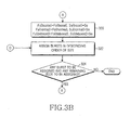
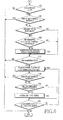
- FIGs. 5A to 5D illustrate a BS's burst assignment procedure including burst fragmentation and an algorithm for filling the remaining slot, in which power boosting/deboosting is taken into consideration, according to an embodiment of the present invention.
- the BS determines a MAP size by estimating MAP overhead necessary for data bursts to be transmitted.
- the MAP size should be set to a large value when there are many data bursts to be transmitted.
- the increase in the MAP size reduces the data burst region size. Therefore, the MAP size and the data burst region size should be properly determined on a trade-off basis.
- the BS calculates N (total number of slots that should be transmitted), So (number of initial data symbols), No (maximum number of slots transmittable in DL subframe determined through MAP size estimation) and the number of DL MAP IEs.
- the BS performs, on each corresponding region, burst concatenation for configuring one burst using the data bursts being transmitted to the same MS, or the PDUs having the same MCS level, to minimize the MAP overhead.
- the BS adjusts QoS priorities disordered due to the concatenation, and calculates size priorities to be used in the burst assignment algorithm.
- the MCS is combinations of modulation schemes and coding schemes, and multiple MCSs with level 1 to level N can be defined according to the number of MCSs.
- the BS compares Fo(total) with the maximum number of subchannels per symbol, and compares Effective Power Fo(total) with the maximum number of subchannels per symbol.
- the Fo(total) is a sum of Fo(boost), Fo(normal) and Fo(deboost)
- the Effective Power Fo(total) is a sum of Effective Power Fo(boost), Effective Power Fo(normal) and Effective Power Fo(deboost). If the Fo(total) or Effective Power Fo(total) is greater than or equal to the maximum number of subchannels per symbol, the BS proceeds to step 508. However, if the Fo(total) or Effective Power Fo(total) is less than the maximum number of subchannels per symbol, the BS proceeds to step 512.
- step 508 the BS determines if the minimum-QoS priority PDU belongs to a boosting region. If the minimum-QoS priority PDU belongs to the boosting region, the BS proceeds to step 514. However, if the minimum-QoS priority PDU does not belong to the boosting region, the BS proceeds to step 510 where the BS determines if the minimum-QoS priority PDU belongs to a normal region. If the minimum-QoS priority PDU belongs to the normal region, the BS proceeds to step 516, and if the minimum-QoS priority PDU does not belong to the normal region, the BS proceeds to step 518.
- the BS calculates Fo(region), No(region) and Ro(region) of each region using Equation (1), and then proceeds to step 520 of FIG. 5B .
- the BS calculates Fo of other regions not including the minimum-QoS priority PDU as ceil(N/So). However, because the minimum-QoS priority PDU undergoes fragmentation, Fo of the region including the minimum-QoS priority PDU is determined as the minimum value using Equation (2) in a relative manner such that it should not exceed the maximum number of subchannels per symbol according to the Fo determined in other regions except for the region to which minimum-QoS priority PDU belongs.
- step 520(A) the BS calculates Fu(region) as Fo(region), and calculates Su(region) as So(region) using Equation (3).
- step 522 the BS assigns bursts in descending order of the size, and then checks in step 524 whether there is any burst to be assigned and there is any remaining slot. If there is any burst to be assigned and there is any remaining slot, the BS proceeds to step 526, and if there is no burst to be assigned or there is no remaining slot, the BS proceeds to step 602(K) of FIG. 6
- step 526 the BS checks whether the burst to be assigned belongs to the boosting region. If it is determined that the burst to be assigned belongs to the boosting region, the BS proceeds to step 530(B), and if the burst to be assigned does not belong to the boosting region, the BS proceeds to step 528 where the BS determines if the burst to be assigned belongs to the normal region. If the burst to be assigned belongs to the normal region, the BS proceeds to step 540(C), and if the burst to be assigned does not belong to the normal region, the BS proceeds to step 550(D).
- step 530(B) the BS compares N(boost) with No(boost) in size. As a result of the comparison, if the N(boost) is less than the No(boost), the BS proceeds to step 536. However, if the N(boost) is greater than or equal to the No(boost), the BS determines in step 532 if fragmentation of the minimum-QoS priority burst is possible. If it is determined that the fragmentation is possible, the BS proceeds to step 534, and if the fragmentation is not possible, the BS proceeds to step 568(J).
- the BS performs fragmentation on the minimum-QoS priority burst estimated in steps 502 and 504.
- the BS fragments the minimum-QoS priority burst such that it can be assigned according to the number of slots except for the slot to which bursts with a QoS priority greater than that of the minimum-QoS priority burst will be assigned.
- the BS assigns the fragmented minimum-QoS priority burst using Fu(boost) and Su(boost) of the assignable boosting region.
- the BS assigns the burst in the increasing direction of the subchannel axis using the full Su(boost), or assigns the burst in the increasing direction of the symbol axis using the full Fu(boost).
- the BS calculates Ru(boost), Fu(boost) and Su(boost), and then proceeds to step 560(H).
- step 540(C) the BS compares N(normal) with No(normal) in size. As a result of the comparison, if the N(normal) is greater than or equal to the No(normal), the BS proceeds to step 542, and if the N(normal) is less than the No(normal), the BS proceeds to step 546. In step 542, the BS determines if fragmentation of the minimum-QoS priority burst is possible. If it is determined that the fragmentation is possible, the BS proceeds to step 544, and if the fragmentation is not possible, the BS proceeds to step 568(J). In step 544, the BS performs fragmentation on the minimum-QoS priority burst estimated in steps 502(F)and 504.
- the BS fragments the minimum-QoS priority burst such that it can be assigned according to the number of slots except for the slot to which bursts with a QoS priority greater than that of the minimum-QoS priority burst will be assigned.
- the BS assigns the fragmented minimum-QoS priority burst using Fu(normal) and Su(normal) of the assignable normal region. That is, to minimize the number of null-padded slots, the BS assigns the burst in the increasing direction of the subchannel axis using the full Su(normal), or assigns the burst in the increasing direction of the symbol axis using the full Fu(normal).
- the BS calculates Ru(normal), Fu(normal) and Su(normal), and then proceeds to step 560(H).
- step 550(D) the BS compares N(deboost) with No(deboost) in size. As a result of the comparison, if the N(deboost) is greater than or equal to the No(deboost), the BS proceeds to step 552, and if the N(deboost) is less than the No(deboost), the BS proceeds to step 556. In step 552, the BS determines if fragmentation of the minimum-QoS priority burst is possible.
- the BS proceeds to step 568(J), and if the fragmentation of the minimum-QoS priority burst is possible, the BS proceeds to step 554 where it performs fragmentation on the minimum-QoS priority burst estimated in steps 502(F) and 504, and then proceeds to step 556.
- the BS fragments the minimum-QoS priority burst such that it can be assigned according to the number of slots except for the slot to which bursts with a QoS priority greater than that of the minimum-QoS priority burst will be assigned.
- the BS assigns the fragmented minimum-QoS priority burst using Fu(deboost) and Su(deboost) of the assignable deboosting region. That is, to minimize the number of null-padded slots, the BS assigns the burst in the increasing direction of the subchannel axis using the full Su(deboost), or assigns the burst in the increasing direction of the symbol axis using the full Fu(deboost).
- the BS calculates Ru(deboost), Fu(deboost) and Su(deboost), and then proceeds to step 560(H).
- the BS compares Ru(region) with Ro(region) in size. If the Ru(region) is less than or equal to the Ro(region) calculated in steps 512 to 518, the BS returns to step 522(E), and if the Ru(region) is greater than the Ro(region) calculated in steps 512 to 518, the BS proceeds to step 562 where it compares the Fo(total) with the maximum number of subchannels per symbol.
- the Fo(total) is a sum of Fo(boost), Fo(normal) and Fo(deboost).
- the BS increases in step 564(P) the Fo(region) of the region in which the Ru(region) is greater than the Ro(region) of the corresponding region, by 1, and then returns to step 552(E).
- the BS removes one minimum-QoS priority PDU in step 566(L) and then returns to step 502.
- the BS does not include the PDU with the next QoS priority of the removed minimum QoS priority in calculating the N.
- step 568(J) the BS removes one minimum-QoS priority PDU, and then returns to step 502(F).
- the BS includes the PDU with the next QoS priority of the removed minimum QoS priority in calculating the N.
- the BS determines if there is any remaining slot, to which bursts are to be assigned, after completing the process of assigning the assignable bursts determined in steps 522 and 524 of FIG 5B in the size order. If there is no remaining slot to which bursts are to be assigned, the BS ends the burst assignment. However, if there is any remaining slot to which bursts are to be assigned, the BS determines in step 604 if the number of MAP symbols increases due to the DL MAP IE that it adds to supplementally assign bursts. If the number of MAP symbols increases, the BS ends the burst assignment.
- the BS determines in step 606 whether fragmentation was performed, i.e. whether step 566(L) of FIG. 5C was performed.
- step 566(L) of FIG. 5C the BS proceeds to step 608, and when step 566(L) of FIG. 5C was not performed, the BS proceeds to step 612.
- step 608 the BS determines if there are slots left in the region to which the last removed PDU has belonged. If there is no slot left in the region to which the last removed PDU has belonged, the BS proceeds to step 612. However, if there are slots left in the region to which the last removed PDU has belonged, the BS assigns in step 610 the PDU last removed in step 566(L) of FIG. 5C , to the remaining slots, and then proceeds to step 612. If the number of the remaining slots is less than the last removed PDU, the BS determines if fragmentation of the PDUs is possible. Depending on the result, the BS fragments and assigns the last removed PDU, or discards it.
- step 612 the BS determines if there is any remaining slot to which bursts are to be assigned, even after the procedure of 602 to 610 for assigning the PDU removed in step 566(L) of FIG. 5C to the remaining slot. If there is no remaining slot to which bursts are to be assigned, the BS ends the burst assignment. However, if there is any remaining slot to which bursts are to be assigned, the BS proceeds to step 614. In step 614, the BS assigns a candidate burst in order of the region having a large number of remaining slots.
- the candidate burst is generated by concatenating PDUs with the same MCS level so that it can fully fill the remaining slot starting from the PDU having the highest QoS priority among the PDUs with the highest MCS level, left in the queue, except for the assignable PDUs determined in step 502(F) of FIG. 5A .
- the BS determines if the number of MAP symbols increases due to the DL MAP IE added to supplementally assign bursts. If the number of MAP symbols increases when the BS supplementally assigns bursts, the BS ends the burst assignment. If the number of MAP symbols does not increase even though the BS supplementally assigns bursts, the BS proceeds to step 618 where it determines if there is any transmittable candidate burst in the corresponding region. If it is determined that there is any candidate burst, the BS assign in step 620 the candidate burst to the empty slots of the corresponding region, and then proceeds to step 622.
- the BS determines if fragmentation of the candidate burst is possible. Depending on the result, the BS fragments and assigns the candidate burst, or discards it. However, if it is determined that there is no candidate burst, the BS determines in step 622 if there is any remaining slot to which data bursts are to be assigned and if there is any assignable candidate burst in the corresponding region. If it is determined that there is any remaining slot to which data bursts are to be assigned and if there is any assignable candidate burst in the corresponding region, the BS returns to step 614. However, if there is no remaining slot to which data bursts are to be assigned or if there is no assignable candidate burst in the corresponding region, the BS ends the burst assignment.
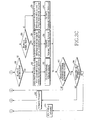
- FIG. 7 illustrates an example of assigning bursts by a burst assignment algorithm considering power boosting/deboosting according to an embodiment of the present invention.
- the downlink frame is divided into a preamble region 701, a MAP region 702, and a data burst assignment region 703.
- a preamble region 701 a preamble region
- a MAP region 702 a data burst assignment region 703.
- the present invention efficiently assigns bursts in the burst assignment region of the downlink frame considering the burst size and the number of null-padded slots to minimize the wasted slots in the BWA communication system, thereby maximizing the entire resource efficiency of the system.
- the present invention performs burst concatenation for configuring one burst using the data bursts being transmitted to the same MS, or the PDUs having the same MCS level, thereby minimizing the MAP overhead.
- the present invention can increase the cell coverage area or cell capacity, and reduce its implementation complexity in the manner of boosting power of the bursts to be assigned to an edge cell user whose CINR is less than the first threshold, and deboosting power of the bursts to be assigned to a near cell user whose CINR is greater than the second threshold, during burst assignment to the downlink frame.
Claims (22)
- Procédé de planification de données dans un système de communication ayant une structure de trame de liaison descendante incluant des régions de commande de puissance d'une région d'amplification pour amplifier la puissance d'une salve de données, une région normale pour conserver la puissance de la salve de données et une région d'atténuation pour atténuer la puissance de la salve de données, le procédé comprenant :la comparaison (204) d'un rapport porteuse sur bruit d'interférence, CINR, d'une première salve de données destinée à être transmise à une station mobile, MS, avec un seuil pour déterminer une première région représentant une région de commande de puissance de la première salve de données ;la détermination (308; 310) d'une région de commande de puissance d'une première unité de données en paquets, PDU, représentant une PDU, avec une priorité de qualité de service, QoS, minimale, parmi les PDU constituant la première salve de données, si le nombre minimum total de sous-canaux nécessaires pour transmettre un nombre total d'intervalles pour la transmission de la première salve de données ayant fait l'objet d'une commande de puissance pour la première région, est supérieur ou égal (306) à un nombre maximum prédéterminé de sous-canaux par symbole ;la détermination (314; 316; 318) d'un nombre minimum Fo de sous-canaux de la première salve de données dans une deuxième région, tel que Fo est inférieur ou égal au nombre maximum de sous-canaux par symbole, en considérant un nombre minimum de sous-canaux de régions de commande de puissance restantes à l'exclusion de la région de commande de puissance déterminée de la première PDU ; etl'assignation (322) à la MS des salves de données à transmettre dans un ordre de taille tel que le nombre d'intervalles remplis de zéros soit réduit au minimum lorsqu'existe un quelconque intervalle auquel les salves de données doivent être assignées, tandis que le nombre maximum de sous-canaux par symbole est supérieur (344) au nombre minimum Fo de sous-canaux de la première salve de données.
- Procédé selon la revendication 1, dans lequel la détermination d'une première région comprend :la comparaison du nombre minimum de sous-canaux nécessaires pour transmettre un nombre total d'intervalles pour transmission de la première salve de données, avec le nombre maximum de sous-canaux par symbole.
- Procédé selon la revendication 1, dans lequel l'assignation comprend :la détermination du nombre minimum de sous-canaux de la première salve de données déterminé dans la première région en tant que nombre Fu de sous-canaux restants pour l'assignation de la première salve de données dans la première région ;la détermination d'un nombre Su de symboles restants pour l'assignation de la première salve de données dans la première région en utilisant l'équation suivante :Su(région)='nombre de symboles dans la sous-trame de liaison descendante'-'nombre de symboles de préambule'-'nombre de symboles de MAP'la détermination du fait qu'il existe de quelconques secondes salves de données à assigner et qu'il existe un quelconque intervalle restant auquel des salves de données doivent être assignées ; etla vérification d'une région de commande de puissance de la seconde salve de données, et l'assignation de la seconde salve de données dans la direction croissante de l'axe d'un sous-canal ou dans la direction croissante de l'axe d'un symbole en utilisant Fu et Su d'une deuxième région représentant une région de commande de puissance de la seconde salve de données vérifiée.
- Procédé selon la revendication 3, dans lequel l'assignation comprend en outre :la comparaison du nombre Ru d'intervalles remplis de zéros accumulés de chaque région parmi la région d'amplification, la région normale et la région d'atténuation de la seconde salve de données, avec un nombre maximum admissible Ro d'intervalles remplis de zéros estimé dans chaque région parmi la région d'amplification, la région normale et la région d'atténuation, et la détermination du fait que Fo est inférieur au nombre maximum de sous-canaux par symbole si Ru d'au moins une région est supérieur à Ro de la région ;si Fo est inférieur au nombre maximum de sous-canaux par symbole, l'incrémentation d'une unité du nombre minimum de sous-canaux nécessaires pour transmettre le nombre total d'intervalles pour transmission de la seconde salve de données dans la région de commande de puissance de la seconde salve de données où Ru est supérieur à Ro ; etsi Fo est supérieur ou égal au nombre maximum de sous-canaux par symbole, la soustraction du nombre d'intervalles par rapport au nombre total d'intervalles pour transmettre la seconde salve de données, dans lequel le nombre d'intervalles correspond à une seconde PDU représentant une PDU de priorité minimale de la seconde salve de données.
- Procédé selon la revendication 1, dans lequel le seuil comporte un premier seuil pour séparer la région d'amplification de la région normale et un second seuil pour séparer la région normale de la région d'atténuation.
- Procédé selon la revendication 5, dans lequel la détermination d'une première région comprend en outre :l'assignation de la première salve de données dans la région d'amplification si le CINR de la MS est inférieur au premier seuil ;l'assignation de la première salve de données dans la région normale si le CINR de la MS est supérieur au premier seuil et inférieur au second seuil ; etl'assignation de la première salve de données dans la région d'atténuation si le CINR de la MS est supérieur au second seuil.
- Procédé selon la revendication 3, dans lequel l'assignation comprend en outre :la vérification d'une région de commande de puissance de la seconde salve de données s'il existe une seconde salve de données à assigner et s'il existe un intervalle auquel des salves de données doivent être assignées ;la détermination du fait qu'une seconde PDU représentant une PDU avec une priorité de QoS minimale de la seconde salve de données peut faire l'objet d'une segmentation, si le nombre N d'intervalles pour transmettre la seconde salve de données dans une troisième région représentant une région de commande de puissance de la seconde salve de données vérifiée est supérieur ou égal à un nombre maximum No d'intervalles pouvant être transmis dans la troisième région ; etla segmentation de la seconde PDU si la seconde PDU peut faire l'objet d'une segmentation.
- Procédé selon la revendication 7, dans lequel la détermination du fait qu'une seconde PDU peut faire l'objet d'une segmentation comprend en outre :si la seconde PDU ne peut pas faire l'objet d'une segmentation, la soustraction d'un nombre d'intervalles correspondant à la seconde PDU par rapport au nombre total d'intervalles pour transmettre la seconde salve de données.
- Procédé selon la revendication 7, dans lequel la détermination du fait qu'une seconde PDU peut faire l'objet d'une segmentation comprend en outre :si la seconde PDU ne peut pas faire l'objet d'une segmentation, la détermination du fait que le nombre de symboles de MAP augmente pendant l'assignation de la seconde salve de données, lorsqu'existe un quelconque intervalle restant auquel la seconde salve de données doit être assignée ;si le nombre de symboles de MAP n'augmente pas, la détermination du fait que le nombre d'intervalles
correspondant à la seconde PDU est soustrait du nombre total d'intervalles pour transmettre la seconde salve de données ;si le nombre d'intervalles correspondant à la seconde PDU est soustrait du nombre total d'intervalles, l'assignation de la seconde PDU à un intervalle restant lorsqu'existe l'intervalle restant auquel aucune salve de données n'est assignée dans la troisième région représentant la région de commande de puissance de la seconde PDU ; ets'il existe un intervalle restant, l'assignation d'une salve de données candidate à l'intervalle restant par ordre de taille. - Procédé selon la revendication 9, comprenant en outre :après assignation de la salve de données candidate, si le nombre de symboles de MAP n'augmente pas, la détermination du fait qu'il existe une autre salve de données candidate pouvant être transmise à la MS ; ets'il existe une autre salve de données candidate et s'il existe un intervalle restant, l'assignation de l'autre salve de données candidate à l'intervalle restant.
- Procédé selon la revendication 9, dans lequel la salve de données candidate est générée par concaténation de PDU avec un même niveau d'aménagement de modulation et de codage, MCS, parmi les PDU avec le niveau de MCS le plus grand d'une salve de données à transmettre à la MS, dans l'ordre d'une PDU ayant la priorité de QoS la plus grande jusqu'à une PDU ayant la priorité de QoS la plus petite.
- Système de planification de données dans un système de communication ayant une structure de trame de liaison descendante incluant des régions de commande de puissance d'une région d'amplification (108 pour amplifier la puissance d'une salve de données, une région normale (110) pour conserver la puissance de la salve de données et une région d'atténuation (112) pour atténuer la puissance de la salve de données, le système comprenant :une station de base, BS, la BS étant adaptée àcomparer un rapport porteuse sur bruit d'interférence, CINR, d'une première salve de données destinée à être transmise à une station mobile, MS, avec un seuil pour déterminer une première région représentant une région de commande de puissance de la première salve de données ;déterminer une région de commande de puissance d'une première unité de données en paquets, PDU, représentant une PDU, avec une priorité de qualité de service, QoS, minimale, parmi les PDU constituant la première salve de données, si le nombre minimum total de sous-canaux nécessaires pour transmettre un nombre total d'intervalles pour la transmission de la première salve de données ayant fait l'objet d'une commande de puissance pour la première région, est supérieur ou égal à un nombre maximum prédéterminé de sous-canaux par symbole ;déterminer un nombre minimum Fo de sous-canaux de la première salve de données dans une deuxième région, tel que Fo est inférieur ou égal au nombre maximum de sous-canaux par symbole, en considérant un nombre minimum de sous-canaux de régions de commande de puissance restantes à l'exclusion de la région de commande de puissance déterminée de la première PDU ; etassigner à la MS des salves de données à transmettre dans un ordre de taille tel que le nombre d'intervalles remplis de zéros soit réduit au minimum lorsqu'existe un quelconque intervalle auquel les salves de données doivent être assignées, tandis que le nombre maximum de sous-canaux par symbole est supérieur (344) au nombre minimum Fo de sous-canaux de la première salve de données.
- Système selon la revendication 12, dans lequel la BS est adaptée à comparer le nombre minimum de sous-canaux nécessaires pour transmettre un nombre total d'intervalles pour transmission de la première salve de données, avec le nombre maximum de sous-canaux par symbole.
- Système selon la revendication 12, dans lequel la BS est adaptée à :déterminer le nombre minimum de sous-canaux de la première salve de données déterminé dans la première région en tant que nombre Fu de sous-canaux restants pour l'assignation de la première salve de données dans la première région, et déterminer un nombre Su de symboles restants pour l'assignation de la première salve de données dans la première région en utilisant l'équation suivante :Su(région)='nombre de symboles dans la sous-trame de liaison descendante'-'nombre de symboles de préambule'- 'nombre de symboles de MAP'et déterminer s'il existe de quelconques secondes salves de données à assigner et s'il existe un quelconque intervalle restant auquel des salves de données doivent être assignées, vérifier une région de commande de puissance de la seconde salve de données, et assigner la seconde salve de données dans la direction croissante de l'axe d'un sous-canal ou dans la direction croissante de l'axe d'un symbole en utilisant Fu et Su d'une deuxième région représentant une région de commande de puissance de la seconde salve de données vérifiée.
- Système selon la revendication 14, dans lequel la BS est adaptée à :comparer le nombre Ru d'intervalles remplis de zéros accumulés de chaque région parmi la région d'amplification, la région normale et la région d'atténuation de la seconde salve de données, avec un nombre maximum admissible Ro d'intervalles remplis de zéros estimé dans chaque région parmi la région d'amplification, la région normale et la région d'atténuation, et déterminer si Fo est inférieur au nombre maximum de sous-canaux par symbole si Ru d'au moins une région est supérieur à Ro de la région ;si Fo est inférieur au nombre maximum de sous-canaux par symbole, incrémenter d'une unité le nombre minimum de sous-canaux nécessaires pour transmettre le nombre total d'intervalles pour transmission de la seconde salve de données dans la région de commande de puissance de la seconde salve de données où Ru est supérieur à Ro ; etsi Fo est supérieur ou égal au nombre maximum de sous-canaux par symbole, soustraire le nombre d'intervalles du nombre total d'intervalles pour transmettre la seconde salve de données, dans lequel le nombre d'intervalles correspond à une seconde PDU représentant une PDU de priorité minimale de la seconde salve de données.
- Système selon la revendication 12, dans lequel le seuil comporte un premier seuil pour séparer la région d'amplification de la région normale et un second seuil pour séparer la région normale de la région d'atténuation.
- Système selon la revendication 16, dans lequel la BS est adaptée à :assigner la première salve de données dans la région d'amplification si le CINR de la MS est inférieur au premier seuil ;assigner la première salve de données dans la région normale si le CINR de la MS est supérieur au premier seuil et inférieur au second seuil ; etassigner la première salve de données dans la région d'atténuation si le CINR de la MS est supérieur au second seuil.
- Système selon la revendication 14, dans lequel la BS est adaptée à :vérifier une région de commande de puissance de la seconde salve de données s'il existe une seconde salve de données à assigner et s'il existe un intervalle auquel des salves de données doivent être assignées ;déterminer si une seconde PDU représentant une PDU avec une priorité de QoS minimale de la seconde salve de données peut faire l'objet d'une segmentation, si le nombre N d'intervalles pour transmettre la seconde salve de données dans une troisième région représentant une région de commande de puissance de la seconde salve de données vérifiée est supérieur ou égal à un nombre maximum No d'intervalles pouvant être transmis dans la troisième région ; etsegmenter la seconde PDU si la seconde PDU peut faire l'objet d'une segmentation.
- Système selon la revendication 18, dans lequel si la seconde PDU ne peut pas faire l'objet d'une segmentation, la BS est adaptée à soustraire un nombre d'intervalles correspondant à la seconde PDU du nombre total d'intervalles pour transmettre la seconde salve de données.
- Système selon la revendication 18, dans lequel la BS est adaptée à :si la seconde PDU ne peut pas faire l'objet d'une segmentation, déterminer si le nombre de symboles de MAP augmente pendant l'assignation de la seconde salve de données, lorsqu'existe un quelconque intervalle restant auquel la seconde salve de données doit être assignée ;si le nombre de symboles de MAP n'augmente pas, déterminer si le nombre d'intervalles correspondant à la seconde PDU est soustrait du nombre total d'intervalles pour transmettre la seconde salve de données ;si le nombre d'intervalles correspondant à la seconde PDU est soustrait du nombre total d'intervalles, assigner la seconde PDU à un intervalle restant lorsqu'existe l'intervalle restant auquel aucune salve de données n'est assignée dans la troisième région représentant la région de commande de puissance de la seconde PDU ; ets'il existe un intervalle restant, assigner une salve de données candidate à l'intervalle restant par ordre de taille.
- Système selon la revendication 20, dans lequel la BS est adaptée à :après assignation de la salve de données candidate, si le nombre de symboles de MAP n'augmente pas, déterminer s'il existe une autre salve de données candidate pouvant être transmise à la MS ; ets'il existe une autre salve de données candidate et s'il existe un intervalle restant, assigner l'autre salve de données candidate à l'intervalle restant.
- Système selon la revendication 20, dans lequel la salve de données candidate est générée par concaténation de PDU avec un même niveau d'aménagement de modulation et de codage, MCS, parmi les PDU avec le niveau de MCS le plus grand d'une salve de données à transmettre à la MS, dans l'ordre d'une PDU ayant la priorité de QoS la plus grande jusqu'à une PDU ayant la priorité de QoS la plus petite.
Applications Claiming Priority (1)
| Application Number | Priority Date | Filing Date | Title |
|---|---|---|---|
| KR20060094182 | 2006-09-27 |
Publications (3)
| Publication Number | Publication Date |
|---|---|
| EP1906548A2 EP1906548A2 (fr) | 2008-04-02 |
| EP1906548A3 EP1906548A3 (fr) | 2013-06-19 |
| EP1906548B1 true EP1906548B1 (fr) | 2014-08-13 |
Family
ID=38924674
Family Applications (1)
| Application Number | Title | Priority Date | Filing Date |
|---|---|---|---|
| EP20070117146 Expired - Fee Related EP1906548B1 (fr) | 2006-09-27 | 2007-09-25 | Procédé et appareil pour planifier des données selon leur puissance dans un système de communication |
Country Status (5)
| Country | Link |
|---|---|
| US (1) | US8031662B2 (fr) |
| EP (1) | EP1906548B1 (fr) |
| JP (1) | JP4494448B2 (fr) |
| KR (1) | KR101002848B1 (fr) |
| CN (1) | CN101183888B (fr) |
Families Citing this family (52)
| Publication number | Priority date | Publication date | Assignee | Title |
|---|---|---|---|---|
| KR100810216B1 (ko) * | 2006-08-01 | 2008-03-06 | 삼성전자주식회사 | 통신 시스템에서 데이터 송신 장치 및 방법 |
| EP1906548B1 (fr) * | 2006-09-27 | 2014-08-13 | Samsung Electronics Co., Ltd. | Procédé et appareil pour planifier des données selon leur puissance dans un système de communication |
| EP2151934A1 (fr) * | 2007-05-28 | 2010-02-10 | Mitsubishi Electric Corporation | Appareil de communication |
| US8203955B2 (en) | 2007-06-21 | 2012-06-19 | Alcatel Lucent | Method and apparatus for scheduling packets in an orthogonal frequency division multiple access (OFDMA) system |
| US7768838B2 (en) * | 2007-10-30 | 2010-08-03 | Micron Technology, Inc. | Operating memory cells |
| US8340060B2 (en) * | 2008-03-03 | 2012-12-25 | Ntt Docomo, Inc. | OFDMA-based co-channel femtocell |
| KR101013491B1 (ko) * | 2008-08-11 | 2011-02-10 | 재단법인서울대학교산학협력재단 | 무선 통신 시스템에서 전력 할당을 위한 장치 및 그 방법 |
| US8843151B2 (en) * | 2008-09-11 | 2014-09-23 | Industrial Technology Research Institute | Systems and methods for providing data communications with burst transmissions |
| CN101729373B (zh) * | 2008-10-29 | 2012-10-17 | 阿尔卡特朗讯 | 对多优先级业务进行调度的方法及装置 |
| JP5286029B2 (ja) * | 2008-10-30 | 2013-09-11 | 京セラ株式会社 | データ送信装置およびデータ送信方法 |
| KR101567893B1 (ko) * | 2009-02-12 | 2015-11-11 | 삼성전자주식회사 | 광대역 무선통신 시스템에서 맵 크기 추정 장치 및 방법 |
| EP2403305A4 (fr) * | 2009-02-24 | 2016-04-06 | Alcatel Lucent | Procédé de planification de ressources, programmateur et station de base |
| US8559458B2 (en) * | 2009-05-27 | 2013-10-15 | Motorola Mobility Llc | Method and apparatus for uplink scheduling in an orthogonal frequency division multiplexing communication system |
| CN101998655B (zh) * | 2009-08-31 | 2013-05-08 | 鼎桥通信技术有限公司 | 一种多载波高速上行分组接入的调度方法 |
| KR101636382B1 (ko) * | 2009-09-28 | 2016-07-20 | 삼성전자주식회사 | 계층-셀 통신 시스템 또는 다중-셀 통신 시스템에서 사용자 스케쥴링 및 송신 전력 제어 방법 및 상기 방법을 위한 장치 |
| CN102088310B (zh) * | 2009-12-04 | 2014-03-12 | 中兴通讯股份有限公司 | 一种提升ofdma系统下行覆盖和吞吐量的方法 |
| KR101578227B1 (ko) | 2010-02-10 | 2015-12-17 | 삼성전자주식회사 | 무선 통신 시스템에서 자원 할당 스케줄링 방법 및 장치 |
| CN102201886B (zh) * | 2010-03-22 | 2014-03-12 | 中兴通讯股份有限公司 | 闭环多输入多输出系统中预编码矩阵的选取方法和系统 |
| US8542667B2 (en) * | 2010-04-14 | 2013-09-24 | Hughes Network Systems, Llc | High capacity satellite communications system |
| CN102076075B (zh) * | 2010-12-23 | 2014-03-19 | 意法·爱立信半导体(北京)有限公司 | 控制对端的数据发送功率的方法、装置以及系统 |
| WO2011127853A2 (fr) * | 2011-05-16 | 2011-10-20 | 华为技术有限公司 | Procédé et dispositif de commande de puissance de liaison descendante wimax |
| US8395985B2 (en) | 2011-07-25 | 2013-03-12 | Ofinno Technologies, Llc | Time alignment in multicarrier OFDM network |
| EP3937551A3 (fr) | 2012-01-25 | 2022-02-09 | Comcast Cable Communications, LLC | Canal d'accès aléatoire dans des communications sans fil à porteuses multiples avec des groupes d'avance temporelle |
| US8526389B2 (en) * | 2012-01-25 | 2013-09-03 | Ofinno Technologies, Llc | Power scaling in multicarrier wireless device |
| US9237537B2 (en) | 2012-01-25 | 2016-01-12 | Ofinno Technologies, Llc | Random access process in a multicarrier base station and wireless device |
| EP2835023B1 (fr) | 2012-04-01 | 2021-09-01 | Comcast Cable Communications, LLC | Configuration de groupe de cellules dans un dispositif sans fil et station de base à groupes d'avance temporelle |
| US11943813B2 (en) | 2012-04-01 | 2024-03-26 | Comcast Cable Communications, Llc | Cell grouping for wireless communications |
| US20130259008A1 (en) | 2012-04-01 | 2013-10-03 | Esmael Hejazi Dinan | Random Access Response Process in a Wireless Communications |
| US8958342B2 (en) | 2012-04-17 | 2015-02-17 | Ofinno Technologies, Llc | Uplink transmission power in a multicarrier wireless device |
| US8989128B2 (en) | 2012-04-20 | 2015-03-24 | Ofinno Technologies, Llc | Cell timing in a wireless device and base station |
| US11582704B2 (en) | 2012-04-16 | 2023-02-14 | Comcast Cable Communications, Llc | Signal transmission power adjustment in a wireless device |
| US11252679B2 (en) | 2012-04-16 | 2022-02-15 | Comcast Cable Communications, Llc | Signal transmission power adjustment in a wireless device |
| EP3337079A1 (fr) | 2012-04-16 | 2018-06-20 | Comcast Cable Communications, LLC | Configuration avec groupes de cellules pour l'émission en liaison montante dans un dispositif sans fil multi-porteuses et station de base avec groupes d'avance de synchronisation |
| US8964593B2 (en) | 2012-04-16 | 2015-02-24 | Ofinno Technologies, Llc | Wireless device transmission power |
| US11825419B2 (en) | 2012-04-16 | 2023-11-21 | Comcast Cable Communications, Llc | Cell timing in a wireless device and base station |
| US9179425B2 (en) | 2012-04-17 | 2015-11-03 | Ofinno Technologies, Llc | Transmit power control in multicarrier communications |
| US9210619B2 (en) | 2012-06-20 | 2015-12-08 | Ofinno Technologies, Llc | Signalling mechanisms for wireless device handover |
| US8971298B2 (en) | 2012-06-18 | 2015-03-03 | Ofinno Technologies, Llc | Wireless device connection to an application server |
| US9107206B2 (en) | 2012-06-18 | 2015-08-11 | Ofinne Technologies, LLC | Carrier grouping in multicarrier wireless networks |
| US9113387B2 (en) | 2012-06-20 | 2015-08-18 | Ofinno Technologies, Llc | Handover signalling in wireless networks |
| US11882560B2 (en) | 2012-06-18 | 2024-01-23 | Comcast Cable Communications, Llc | Carrier grouping in multicarrier wireless networks |
| US9179457B2 (en) | 2012-06-20 | 2015-11-03 | Ofinno Technologies, Llc | Carrier configuration in wireless networks |
| US11622372B2 (en) | 2012-06-18 | 2023-04-04 | Comcast Cable Communications, Llc | Communication device |
| US9084228B2 (en) | 2012-06-20 | 2015-07-14 | Ofinno Technologies, Llc | Automobile communication device |
| CN103517394B (zh) | 2012-06-30 | 2017-08-18 | 华为技术有限公司 | 用户数据调度方法和装置 |
| CN103875278A (zh) * | 2012-09-20 | 2014-06-18 | 华为技术有限公司 | 数据传输方法和设备 |
| US20150188845A1 (en) * | 2014-01-02 | 2015-07-02 | Broadcom Corporation | Mitigating bandwidth degradation in a switching device |
| KR102124610B1 (ko) * | 2014-08-20 | 2020-06-19 | 삼성전자주식회사 | 무선 통신 시스템에서 낮은 복잡도로 복호를 수행하기 위한 방법 및 장치 |
| KR102297167B1 (ko) * | 2015-03-18 | 2021-09-01 | 에스케이플래닛 주식회사 | 위치 측정이 이루어지는 단말 및 그 동작 방법 |
| WO2018056707A1 (fr) * | 2016-09-22 | 2018-03-29 | 엘지전자 주식회사 | Procédé de réduction d'interférence entre un signal de liaison montante et un signal de liaison descendante, et dispositif associé |
| EP3618513B1 (fr) * | 2017-06-16 | 2021-08-11 | Huawei Technologies Co., Ltd. | Procédé, dispositif et système de transmission de service |
| US11516756B2 (en) | 2021-03-29 | 2022-11-29 | Hewlett Packard Enterprise Development Lp | Scheduler optimization for OFDMA downlink transmissions |
Family Cites Families (12)
| Publication number | Priority date | Publication date | Assignee | Title |
|---|---|---|---|---|
| EP1209936A1 (fr) * | 2000-11-22 | 2002-05-29 | Lucent Technologies Inc. | Procédé et système pour l'ordonnancement de la transmission de paquets UMTS dans des canaux descendants |
| EP1209940A1 (fr) * | 2000-11-22 | 2002-05-29 | Lucent Technologies Inc. | Procédé et système pour l'ordonnancement de la transmission de paquets UMTS dans des canaux montants |
| US7072413B2 (en) * | 2001-05-17 | 2006-07-04 | Qualcomm, Incorporated | Method and apparatus for processing data for transmission in a multi-channel communication system using selective channel inversion |
| TWI221391B (en) | 2002-03-27 | 2004-09-21 | Benq Corp | System and method for scheduling and transmitting protocol data units |
| JP2004356921A (ja) * | 2003-05-29 | 2004-12-16 | Hitachi Ltd | 無線通信装置 |
| US7324522B2 (en) * | 2003-09-18 | 2008-01-29 | Raytheon Company | Encapsulating packets into a frame for a network |
| WO2005099290A1 (fr) * | 2004-04-05 | 2005-10-20 | Nortel Networks Limited | Procedes de prise en charge de la transmission mimo dans des applications ofdm |
| KR100810290B1 (ko) * | 2004-12-14 | 2008-03-07 | 삼성전자주식회사 | 무선 통신 시스템에서 데이터 버스트 할당 방법 및 시스템 |
| AU2006205296B2 (en) | 2005-01-11 | 2009-02-19 | Nokia Technologies Oy | Method and system for indicating data burst allocation in a wireless communication system |
| KR20070010597A (ko) * | 2005-07-19 | 2007-01-24 | 삼성전자주식회사 | 광대역 무선 접속 통신 시스템에서 하향링크 자원 할당방법 |
| EP1906548B1 (fr) * | 2006-09-27 | 2014-08-13 | Samsung Electronics Co., Ltd. | Procédé et appareil pour planifier des données selon leur puissance dans un système de communication |
| US7912005B2 (en) * | 2007-01-29 | 2011-03-22 | Samsung Electronics Co., Ltd | Method and apparatus for configuring downlink frame in a communication system |
-
2007
- 2007-09-25 EP EP20070117146 patent/EP1906548B1/fr not_active Expired - Fee Related
- 2007-09-25 CN CN2007101596587A patent/CN101183888B/zh not_active Expired - Fee Related
- 2007-09-26 JP JP2007249515A patent/JP4494448B2/ja active Active
- 2007-09-27 KR KR20070097347A patent/KR101002848B1/ko active IP Right Grant
- 2007-09-27 US US11/862,754 patent/US8031662B2/en active Active
Also Published As
| Publication number | Publication date |
|---|---|
| US8031662B2 (en) | 2011-10-04 |
| KR101002848B1 (ko) | 2010-12-22 |
| JP2008086018A (ja) | 2008-04-10 |
| CN101183888A (zh) | 2008-05-21 |
| KR20080028820A (ko) | 2008-04-01 |
| EP1906548A3 (fr) | 2013-06-19 |
| EP1906548A2 (fr) | 2008-04-02 |
| US20080075027A1 (en) | 2008-03-27 |
| CN101183888B (zh) | 2012-12-05 |
| JP4494448B2 (ja) | 2010-06-30 |
Similar Documents
| Publication | Publication Date | Title |
|---|---|---|
| EP1906548B1 (fr) | Procédé et appareil pour planifier des données selon leur puissance dans un système de communication | |
| US7835281B2 (en) | Method and system for allocating resources in a communication system | |
| US7706804B2 (en) | Apparatus and method for allocating resources in a communication system | |
| RU2289210C2 (ru) | Устройство и способ передачи/приема данных в системе связи, использующей схему множественного доступа | |
| EP2237441B1 (fr) | Procédé et appareil de contrôle de transmissions dans un système de communications | |
| EP1587268B1 (fr) | Appareil et procédé pour le contrôle de la puissance d'émission dans des systèmes de communications utilisant plusiers facteurs de réutilisation de fréquence | |
| EP1912464B1 (fr) | Procédé et appareil de contrôle d'admission de connexion dans un système d'accès sans fil à large bande | |
| US20070086474A1 (en) | Method for estimating a map size in a wireless mobile communication system | |
| US20090059859A1 (en) | Communication device | |
| US20070115880A1 (en) | Apparatus and method for uplink scheduling in a communication system | |
| US20110096708A1 (en) | Wireless scheduling systems and methods | |
| KR20070041214A (ko) | 무선 이동 통신 시스템에서 상향링크 스케줄링 방법 | |
| EP2163060B1 (fr) | Restructuration de profil de puissance dans des symboles du ofdma downlink map en fonction de l'état du canal | |
| EP1950905B1 (fr) | Procédé et appareil pour configurer la trame de liaison descendante dans un système de communication | |
| US9191860B2 (en) | Apparatus and method for estimating size of map message in broadband wireless communication | |
| EP2452527B1 (fr) | Attribution de ressources fondée sur la priorité et la puissance de signalisation | |
| KR101567893B1 (ko) | 광대역 무선통신 시스템에서 맵 크기 추정 장치 및 방법 | |
| US7903627B2 (en) | Method for generating burst in a communication system | |
| US8630675B2 (en) | Method for controlling power in a cellular network with a surplus of transmission resources | |
| US8320320B2 (en) | Method and system for downlink transmission scheduling in multi-carrier networks |
Legal Events
| Date | Code | Title | Description |
|---|---|---|---|
| PUAI | Public reference made under article 153(3) epc to a published international application that has entered the european phase |
Free format text: ORIGINAL CODE: 0009012 |
|
| 17P | Request for examination filed |
Effective date: 20070925 |
|
| AK | Designated contracting states |
Kind code of ref document: A2 Designated state(s): AT BE BG CH CY CZ DE DK EE ES FI FR GB GR HU IE IS IT LI LT LU LV MC MT NL PL PT RO SE SI SK TR |
|
| AX | Request for extension of the european patent |
Extension state: AL BA HR MK YU |
|
| RAP1 | Party data changed (applicant data changed or rights of an application transferred) |
Owner name: SAMSUNG ELECTRONICS CO., LTD. |
|
| PUAL | Search report despatched |
Free format text: ORIGINAL CODE: 0009013 |
|
| AK | Designated contracting states |
Kind code of ref document: A3 Designated state(s): AT BE BG CH CY CZ DE DK EE ES FI FR GB GR HU IE IS IT LI LT LU LV MC MT NL PL PT RO SE SI SK TR |
|
| AX | Request for extension of the european patent |
Extension state: AL BA HR MK RS |
|
| RIC1 | Information provided on ipc code assigned before grant |
Ipc: H04W 52/34 20090101ALI20130510BHEP Ipc: H04W 52/28 20090101ALI20130510BHEP Ipc: H04B 7/005 20060101AFI20130510BHEP |
|
| REG | Reference to a national code |
Ref country code: DE Ref legal event code: R079 Ref document number: 602007038063 Country of ref document: DE Free format text: PREVIOUS MAIN CLASS: H04B0007005000 Ipc: H04W0052280000 |
|
| AKX | Designation fees paid |
Designated state(s): DE FR GB IT NL |
|
| GRAP | Despatch of communication of intention to grant a patent |
Free format text: ORIGINAL CODE: EPIDOSNIGR1 |
|
| RIC1 | Information provided on ipc code assigned before grant |
Ipc: H04W 52/34 20090101ALI20140203BHEP Ipc: H04W 52/28 20090101AFI20140203BHEP Ipc: H04W 52/24 20090101ALN20140203BHEP |
|
| INTG | Intention to grant announced |
Effective date: 20140312 |
|
| RIN1 | Information on inventor provided before grant (corrected) |
Inventor name: JEON, JAE-HO Inventor name: KIM, JUNG-WON Inventor name: LEE, HEE-KWANG |
|
| GRAS | Grant fee paid |
Free format text: ORIGINAL CODE: EPIDOSNIGR3 |
|
| GRAA | (expected) grant |
Free format text: ORIGINAL CODE: 0009210 |
|
| AK | Designated contracting states |
Kind code of ref document: B1 Designated state(s): DE FR GB IT NL |
|
| REG | Reference to a national code |
Ref country code: GB Ref legal event code: FG4D |
|
| REG | Reference to a national code |
Ref country code: DE Ref legal event code: R082 Ref document number: 602007038063 Country of ref document: DE Representative=s name: GRUENECKER PATENT- UND RECHTSANWAELTE PARTG MB, DE Ref country code: DE Ref legal event code: R082 Ref document number: 602007038063 Country of ref document: DE Representative=s name: GRUENECKER, KINKELDEY, STOCKMAIR & SCHWANHAEUS, DE |
|
| REG | Reference to a national code |
Ref country code: DE Ref legal event code: R096 Ref document number: 602007038063 Country of ref document: DE Effective date: 20140918 |
|
| REG | Reference to a national code |
Ref country code: NL Ref legal event code: T3 |
|
| PG25 | Lapsed in a contracting state [announced via postgrant information from national office to epo] |
Ref country code: IT Free format text: LAPSE BECAUSE OF FAILURE TO SUBMIT A TRANSLATION OF THE DESCRIPTION OR TO PAY THE FEE WITHIN THE PRESCRIBED TIME-LIMIT Effective date: 20140813 |
|
| REG | Reference to a national code |
Ref country code: DE Ref legal event code: R097 Ref document number: 602007038063 Country of ref document: DE |
|
| PLBE | No opposition filed within time limit |
Free format text: ORIGINAL CODE: 0009261 |
|
| STAA | Information on the status of an ep patent application or granted ep patent |
Free format text: STATUS: NO OPPOSITION FILED WITHIN TIME LIMIT |
|
| REG | Reference to a national code |
Ref country code: FR Ref legal event code: ST Effective date: 20150529 |
|
| 26N | No opposition filed |
Effective date: 20150515 |
|
| PG25 | Lapsed in a contracting state [announced via postgrant information from national office to epo] |
Ref country code: FR Free format text: LAPSE BECAUSE OF NON-PAYMENT OF DUE FEES Effective date: 20141013 |
|
| PGFP | Annual fee paid to national office [announced via postgrant information from national office to epo] |
Ref country code: NL Payment date: 20180821 Year of fee payment: 12 Ref country code: DE Payment date: 20180820 Year of fee payment: 12 |
|
| PGFP | Annual fee paid to national office [announced via postgrant information from national office to epo] |
Ref country code: GB Payment date: 20180822 Year of fee payment: 12 |
|
| REG | Reference to a national code |
Ref country code: DE Ref legal event code: R119 Ref document number: 602007038063 Country of ref document: DE |
|
| REG | Reference to a national code |
Ref country code: NL Ref legal event code: MM Effective date: 20191001 |
|
| PG25 | Lapsed in a contracting state [announced via postgrant information from national office to epo] |
Ref country code: NL Free format text: LAPSE BECAUSE OF NON-PAYMENT OF DUE FEES Effective date: 20191001 Ref country code: DE Free format text: LAPSE BECAUSE OF NON-PAYMENT OF DUE FEES Effective date: 20200401 |
|
| GBPC | Gb: european patent ceased through non-payment of renewal fee |
Effective date: 20190925 |
|
| PG25 | Lapsed in a contracting state [announced via postgrant information from national office to epo] |
Ref country code: GB Free format text: LAPSE BECAUSE OF NON-PAYMENT OF DUE FEES Effective date: 20190925 |