EP1657475A2 - Dispositif de changement de vitesses rotatif pour boîte de vitesses de véhicule automobile - Google Patents
Dispositif de changement de vitesses rotatif pour boîte de vitesses de véhicule automobile Download PDFInfo
- Publication number
- EP1657475A2 EP1657475A2 EP05270077A EP05270077A EP1657475A2 EP 1657475 A2 EP1657475 A2 EP 1657475A2 EP 05270077 A EP05270077 A EP 05270077A EP 05270077 A EP05270077 A EP 05270077A EP 1657475 A2 EP1657475 A2 EP 1657475A2
- Authority
- EP
- European Patent Office
- Prior art keywords
- selector
- control unit
- transmission control
- transmission
- rotary
- Prior art date
- Legal status (The legal status is an assumption and is not a legal conclusion. Google has not performed a legal analysis and makes no representation as to the accuracy of the status listed.)
- Granted
Links
- 230000005540 biological transmission Effects 0.000 title claims abstract description 124
- 230000007246 mechanism Effects 0.000 title claims abstract description 64
- 238000012937 correction Methods 0.000 claims abstract description 28
- 230000008859 change Effects 0.000 claims abstract description 5
- 238000000034 method Methods 0.000 claims description 12
- 230000033001 locomotion Effects 0.000 claims description 7
- 238000004891 communication Methods 0.000 claims description 2
- 101000619552 Homo sapiens Prion-like protein doppel Proteins 0.000 description 4
- 102100022209 Prion-like protein doppel Human genes 0.000 description 4
- 230000007935 neutral effect Effects 0.000 description 4
- 229910000831 Steel Inorganic materials 0.000 description 3
- 238000005286 illumination Methods 0.000 description 3
- 239000010959 steel Substances 0.000 description 3
- 230000004048 modification Effects 0.000 description 2
- 238000012986 modification Methods 0.000 description 2
- 238000007792 addition Methods 0.000 description 1
- 238000000418 atomic force spectrum Methods 0.000 description 1
- 230000000994 depressogenic effect Effects 0.000 description 1
- 238000001514 detection method Methods 0.000 description 1
- 238000010586 diagram Methods 0.000 description 1
- 229920003023 plastic Polymers 0.000 description 1
- 238000012545 processing Methods 0.000 description 1
- 230000007704 transition Effects 0.000 description 1
Images


Classifications
-
- F—MECHANICAL ENGINEERING; LIGHTING; HEATING; WEAPONS; BLASTING
- F16—ENGINEERING ELEMENTS AND UNITS; GENERAL MEASURES FOR PRODUCING AND MAINTAINING EFFECTIVE FUNCTIONING OF MACHINES OR INSTALLATIONS; THERMAL INSULATION IN GENERAL
- F16H—GEARING
- F16H59/00—Control inputs to control units of change-speed-, or reversing-gearings for conveying rotary motion
- F16H59/02—Selector apparatus
- F16H59/04—Ratio selector apparatus
-
- B—PERFORMING OPERATIONS; TRANSPORTING
- B60—VEHICLES IN GENERAL
- B60K—ARRANGEMENT OR MOUNTING OF PROPULSION UNITS OR OF TRANSMISSIONS IN VEHICLES; ARRANGEMENT OR MOUNTING OF PLURAL DIVERSE PRIME-MOVERS IN VEHICLES; AUXILIARY DRIVES FOR VEHICLES; INSTRUMENTATION OR DASHBOARDS FOR VEHICLES; ARRANGEMENTS IN CONNECTION WITH COOLING, AIR INTAKE, GAS EXHAUST OR FUEL SUPPLY OF PROPULSION UNITS IN VEHICLES
- B60K35/00—Instruments specially adapted for vehicles; Arrangement of instruments in or on vehicles
- B60K35/10—Input arrangements, i.e. from user to vehicle, associated with vehicle functions or specially adapted therefor
-
- F—MECHANICAL ENGINEERING; LIGHTING; HEATING; WEAPONS; BLASTING
- F16—ENGINEERING ELEMENTS AND UNITS; GENERAL MEASURES FOR PRODUCING AND MAINTAINING EFFECTIVE FUNCTIONING OF MACHINES OR INSTALLATIONS; THERMAL INSULATION IN GENERAL
- F16H—GEARING
- F16H59/00—Control inputs to control units of change-speed-, or reversing-gearings for conveying rotary motion
- F16H59/02—Selector apparatus
- F16H59/08—Range selector apparatus
-
- G—PHYSICS
- G05—CONTROLLING; REGULATING
- G05G—CONTROL DEVICES OR SYSTEMS INSOFAR AS CHARACTERISED BY MECHANICAL FEATURES ONLY
- G05G1/00—Controlling members, e.g. knobs or handles; Assemblies or arrangements thereof; Indicating position of controlling members
- G05G1/08—Controlling members for hand actuation by rotary movement, e.g. hand wheels
- G05G1/087—Controlling members for hand actuation by rotary movement, e.g. hand wheels retractable; Flush control knobs
-
- G—PHYSICS
- G05—CONTROLLING; REGULATING
- G05G—CONTROL DEVICES OR SYSTEMS INSOFAR AS CHARACTERISED BY MECHANICAL FEATURES ONLY
- G05G1/00—Controlling members, e.g. knobs or handles; Assemblies or arrangements thereof; Indicating position of controlling members
- G05G1/08—Controlling members for hand actuation by rotary movement, e.g. hand wheels
- G05G1/10—Details, e.g. of discs, knobs, wheels or handles
- G05G1/105—Details, e.g. of discs, knobs, wheels or handles comprising arrangements for illumination
-
- G—PHYSICS
- G05—CONTROLLING; REGULATING
- G05G—CONTROL DEVICES OR SYSTEMS INSOFAR AS CHARACTERISED BY MECHANICAL FEATURES ONLY
- G05G5/00—Means for preventing, limiting or returning the movements of parts of a control mechanism, e.g. locking controlling member
- G05G5/03—Means for enhancing the operator's awareness of arrival of the controlling member at a command or datum position; Providing feel, e.g. means for creating a counterforce
-
- G—PHYSICS
- G05—CONTROLLING; REGULATING
- G05G—CONTROL DEVICES OR SYSTEMS INSOFAR AS CHARACTERISED BY MECHANICAL FEATURES ONLY
- G05G5/00—Means for preventing, limiting or returning the movements of parts of a control mechanism, e.g. locking controlling member
- G05G5/06—Means for preventing, limiting or returning the movements of parts of a control mechanism, e.g. locking controlling member for holding members in one or a limited number of definite positions only
-
- B—PERFORMING OPERATIONS; TRANSPORTING
- B60—VEHICLES IN GENERAL
- B60K—ARRANGEMENT OR MOUNTING OF PROPULSION UNITS OR OF TRANSMISSIONS IN VEHICLES; ARRANGEMENT OR MOUNTING OF PLURAL DIVERSE PRIME-MOVERS IN VEHICLES; AUXILIARY DRIVES FOR VEHICLES; INSTRUMENTATION OR DASHBOARDS FOR VEHICLES; ARRANGEMENTS IN CONNECTION WITH COOLING, AIR INTAKE, GAS EXHAUST OR FUEL SUPPLY OF PROPULSION UNITS IN VEHICLES
- B60K2360/00—Indexing scheme associated with groups B60K35/00 or B60K37/00 relating to details of instruments or dashboards
- B60K2360/126—Rotatable input devices for instruments
-
- F—MECHANICAL ENGINEERING; LIGHTING; HEATING; WEAPONS; BLASTING
- F16—ENGINEERING ELEMENTS AND UNITS; GENERAL MEASURES FOR PRODUCING AND MAINTAINING EFFECTIVE FUNCTIONING OF MACHINES OR INSTALLATIONS; THERMAL INSULATION IN GENERAL
- F16H—GEARING
- F16H59/00—Control inputs to control units of change-speed-, or reversing-gearings for conveying rotary motion
- F16H59/02—Selector apparatus
- F16H59/08—Range selector apparatus
- F16H2059/081—Range selector apparatus using knops or discs for rotary range selection
-
- F—MECHANICAL ENGINEERING; LIGHTING; HEATING; WEAPONS; BLASTING
- F16—ENGINEERING ELEMENTS AND UNITS; GENERAL MEASURES FOR PRODUCING AND MAINTAINING EFFECTIVE FUNCTIONING OF MACHINES OR INSTALLATIONS; THERMAL INSULATION IN GENERAL
- F16H—GEARING
- F16H61/00—Control functions within control units of change-speed- or reversing-gearings for conveying rotary motion ; Control of exclusively fluid gearing, friction gearing, gearings with endless flexible members or other particular types of gearing
- F16H61/12—Detecting malfunction or potential malfunction, e.g. fail safe; Circumventing or fixing failures
- F16H2061/1244—Keeping the current state
-
- F—MECHANICAL ENGINEERING; LIGHTING; HEATING; WEAPONS; BLASTING
- F16—ENGINEERING ELEMENTS AND UNITS; GENERAL MEASURES FOR PRODUCING AND MAINTAINING EFFECTIVE FUNCTIONING OF MACHINES OR INSTALLATIONS; THERMAL INSULATION IN GENERAL
- F16H—GEARING
- F16H61/00—Control functions within control units of change-speed- or reversing-gearings for conveying rotary motion ; Control of exclusively fluid gearing, friction gearing, gearings with endless flexible members or other particular types of gearing
- F16H61/16—Inhibiting or initiating shift during unfavourable conditions, e.g. preventing forward reverse shift at high vehicle speed, preventing engine over speed
- F16H2061/165—Preventing reverse gear shifts if vehicle speed is too high for safe shifting
-
- F—MECHANICAL ENGINEERING; LIGHTING; HEATING; WEAPONS; BLASTING
- F16—ENGINEERING ELEMENTS AND UNITS; GENERAL MEASURES FOR PRODUCING AND MAINTAINING EFFECTIVE FUNCTIONING OF MACHINES OR INSTALLATIONS; THERMAL INSULATION IN GENERAL
- F16H—GEARING
- F16H63/00—Control outputs from the control unit to change-speed- or reversing-gearings for conveying rotary motion or to other devices than the final output mechanism
- F16H63/40—Control outputs from the control unit to change-speed- or reversing-gearings for conveying rotary motion or to other devices than the final output mechanism comprising signals other than signals for actuating the final output mechanisms
- F16H63/42—Ratio indicator devices
- F16H2063/423—Range indicators for automatic transmissions, e.g. showing selected range or mode
-
- F—MECHANICAL ENGINEERING; LIGHTING; HEATING; WEAPONS; BLASTING
- F16—ENGINEERING ELEMENTS AND UNITS; GENERAL MEASURES FOR PRODUCING AND MAINTAINING EFFECTIVE FUNCTIONING OF MACHINES OR INSTALLATIONS; THERMAL INSULATION IN GENERAL
- F16H—GEARING
- F16H61/00—Control functions within control units of change-speed- or reversing-gearings for conveying rotary motion ; Control of exclusively fluid gearing, friction gearing, gearings with endless flexible members or other particular types of gearing
- F16H61/16—Inhibiting or initiating shift during unfavourable conditions, e.g. preventing forward reverse shift at high vehicle speed, preventing engine over speed
-
- F—MECHANICAL ENGINEERING; LIGHTING; HEATING; WEAPONS; BLASTING
- F16—ENGINEERING ELEMENTS AND UNITS; GENERAL MEASURES FOR PRODUCING AND MAINTAINING EFFECTIVE FUNCTIONING OF MACHINES OR INSTALLATIONS; THERMAL INSULATION IN GENERAL
- F16H—GEARING
- F16H61/00—Control functions within control units of change-speed- or reversing-gearings for conveying rotary motion ; Control of exclusively fluid gearing, friction gearing, gearings with endless flexible members or other particular types of gearing
- F16H61/22—Locking of the control input devices
Definitions
- the present invention relates to a rotatable selector mechanism for a motor vehicle transmission, more specifically an automatic or semi-automatic vehicle transmission actuated by shift-by-wire.
- GB 2310693 shows a rotatable selector mechanism which includes a rotary switch with a pointer.
- the rotary switch can be grasped by the driver and rotated around an axis to select the operating mode of the transmission by pointing the pointer towards indicia constituting the letters PRND corresponding to Park (P), Reverse (R), Neutral (N) and Drive (D) modes respectively in the transmission.
- the rotation of the rotary switch transmits a control signal indicating a desired drive condition to the vehicle transmission.
- Such transmissions operated by shift-by-wire commonly include a wide variety of sensors, switches, and other controls. In the event that any of these components fails, the transmission may cease to function.
- the transmission control unit switches to a failure or 'limp home' mode which is designed to ensure that, as far as possible, the vehicle will be drivable and safe. Generally in this mode the transmission control will attempt to maintain the current gear and the failure is indicated to the driver by means of a warning light or text message.
- shift-by-wire transmissions may include an emergency park release to shift the automatic transmission into Neutral to allow the vehicle to be towed away. This operation occurs under certain fault conditions where the selector mechanism cannot be actuated to select a transmission mode, for instance when no power can be supplied to the selector mechanism or a mechanical fault in the transmission prevents the driver from shifting into a mode other than the current mode.
- a rotatable selector mechanism for a motor vehicle transmission having a number of operating modes, the selector mechanism having a housing, a rotary handle movable in the housing between a number of selector positions, each position being associated with a respective one of the operating modes of the transmission, a rotary selector which in normal use of the selector mechanism is connected to the rotary handle so as to rotate with the rotary handle, sensor means for sensing the position of the rotary selector and generating selector signals to a transmission control unit which in use supplies control signals to the transmission, an indexing means for maintaining the rotary handle in each of its positions, a drive correction means and clutch devices to engage the rotary selector to one of the rotary handle and the drive correction means, wherein the clutch devices and the drive corrections means in use are controlled by the transmission control unit to move the rotary selector from a selector position selected by the driver by means of the rotary handle to another selector position representative of the operating mode of the transmission by means of the drive correction
- the selector mechanism further comprises a dynamic indicator which in use is arranged to indicate the operating mode of the transmission.
- the dynamic indicator in use is connected to the transmission control unit to be visible when the vehicle is to be driven and move with the rotary selector.
- the dynamic indicator comprises an illuminated pointer and an arrangement of illuminated labels indicating the selector mode.
- the rotary handle has a top surface and the illuminated pointer is constituted by a one of several light sources circumferentially distributed behind the top surface of the rotary handle.
- the selector mechanism may further comprise a retractor actuator which in use is controlled by the transmission control unit to displace the rotary handle between an active position where it can be manually moved between the selector positions by the driver of the vehicle, and an inactive position in which it is retracted inside the housing where it cannot be readily moved by the driver.
- a retractor actuator which in use is controlled by the transmission control unit to displace the rotary handle between an active position where it can be manually moved between the selector positions by the driver of the vehicle, and an inactive position in which it is retracted inside the housing where it cannot be readily moved by the driver.
- the rotary selector comprises a detent plate having notches for cooperation with a spring-loaded detent member carried by the housing.
- the detent plate may have a slot which cooperates with a stop to limit the rotation of the detent plate between the two extreme selectable modes of the transmission.
- the selector mechanism also comprises a locking device which in use is controlled by the transmission control unit to prevent rotation of the rotary handle when disconnected from the rotary selector.
- one of the selector positions is a manual mode in which position the selector mechanism is operable for use with an auxiliary selector in order to control the gear ratios of the transmission in a pulse manner.
- the invention also provides, according to another aspect, a transmission control system for a motor vehicle transmission having a transmission control unit which in use is connected to a communication port at which data relating to the vehicle's operation are available and including a selector mechanism which is in accordance with said first aspect.
- the invention also provides, according to a further aspect, a method of controlling a rotatable selector mechanism according to said first aspect when installed in a motor vehicle and the transmission control unit is in receipt of a data relating to the operational state of the vehicle in which the transmission control unit determines, after receiving a signal of the sensors, whether the selector mode is available and if the selector mode is unavailable the transmission control unit operates the clutch devices to engage the rotary selector to the drive correction means and disengage the rotary selector from the rotary handle, then send a command to the drive correction means to return the rotary selector to the previous gear position.
- the method includes sending a command from the transmission control unit to the dynamic indicator to indicate the mode of the transmission according to the motion of the rotary selector.
- the transmission control unit sends a command to turn the illuminated pointer off and a command to illuminate the label of the current selector mode.
- the method includes sending a command from the transmission control unit to the retractor actuator to move the rotary handle to the active position when the engine is running and to move the rotary handle to the inactive position when the engine is stopped.
- the transmission control unit if the transmission control unit detects or receives a failure signal, the transmission control unit sends a command to the retractor actuator to move the selector towards the inactive position from the active position.
- the selector mechanism includes a locking device
- the transmission control unit detects or receives a failure signal, the transmission control unit sends a command to the locking device to prevent rotational movement of the rotary handle.
- the selector mechanism includes an auxiliary selector and if the transmission control unit detects or receives a signal from the auxiliary selector, the transmission control unit sends a command to the drive correction means and the dynamic indicator so as to rotate the rotary selector and change the indication of the dynamic indicator from indicating a Drive mode to indicating a Manual mode.
- the transmission control unit may send a command to the drive correction means and the dynamic indicator so as to rotate the rotary selector and change the indication of the dynamic indicator from the Manual mode to the Drive mode.
- a rotatable selector mechanism 10 for actuating an automatic vehicle transmission 11 driven by an engine 12.
- the rotatable selector mechanism 10 is located in an upper surface of a console mounted between a driver's seat and a passenger seat.
- the selector mechanism 10 includes a housing formed by a base 13 and a part 14 of the console inside which a rotary handle in the form of a selector knob 15 is rotatable around a substantially vertical fixed shaft 17 mounted to the base 13.
- the selector knob 15 can be grasped by the driver and rotated around the shaft 17 to select the operating mode of the transmission by pointing an illuminated pointer 16 towards one of a number of labels constituted by the letters PRND.
- These letters correspond to the Park (P), Reverse (R), Neutral (N) and Drive (D) modes respectively in the automatic transmission (Fig.1) and are arranged in a straight line near the selector knob 15.
- Each label P, R, N and D can be illuminated, e.g. by a LED (light emitting diode) 18 located underneath the upper surface of the console 14, each LED 18 being switched on or off according to the position of the illuminated pointer 16 as it will be described in further detail.
- a LED light emitting diode
- the illuminated pointer 16 is constituted by one 19 of several light sources 20, for example LEDs, circumferentially distributed behind the top surface 21 of the selector knob 15, which is illuminated when the vehicle is to be driven, e.g. when the driver turns the engine ignition on.
- the arrangement of labels PRND and illuminated pointer 16 is conveniently referred to as a dynamic indicator for reasons which will be explained.
- the surface of the selector knob 15 includes a metallic centre piece 22 and a frosted transparent plastics ring 23 so that the LEDs 20 cannot be seen if not illuminated.
- the selector mechanism further includes, between the selector knob 15 and the base 13, a cam plate or detent plate 24 which is rotatable around the shaft 17.
- the detent plate 24 forms part of a rotary selector 9 which is normally connected to the selector knob 15.
- the detent plate 24 is connected to a sensor means in order to detect a position of the selector knob 15 and to transmit an input to a transmission control unit 26 (Fig.8).
- This sensor means includes a sensor or encoder 25 that reads scan marks on a disc 27 fixed to the detent plate 24 to provide a sensor output signal which is representative of the direction and magnitude of the motion of the detent plate 24.
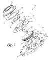
- the detent plate 24 is provided on its periphery with notches 29 over a sector 28 and these can be engaged successively by a spring-loaded detent member 30 (in this example a cam detent pin) when the detent plate 24 rotates, as illustrated in Fig.6 and Fig.7.
- a spring-loaded detent member 30 in this example a cam detent pin
- These notches 29 are arranged in such a way that each selection mode P, R, N, D and optional a manual mode (M) corresponds to an angular position of the detent plate 24.
- M manual mode
- the cooperation between the detent pin 30 and the notches 29 forms an indexing means ensuring the immobilization of the selector knob 15 in its different positions, respectively P, R, N and D.
- the depth and the shape of each notch are different for each position of the selector knob 15 so that not only is the driver able to feel the transition from one position to another but can also infer the mode selected by the feel of the detent.
- the detent plate 24 is provided on its periphery with a slot 32 which extends over a sector 31 and this cooperates with a pin 33 which acts as a fixed end stop for the detent plate 24 when the pin 33 abuts either end of the slot 32.
- the selector knob 15 and the detent plate 24 are connected to one another by means of a first clutch device.
- the first clutch device comprises an electro-magnet clamp 34 vertically fixed on the detent plate 24 in front of a first steel ring 35 fixed to the selector knob 15.
- the electro-magnet clamp is controlled by the transmission control unit 26 in order to engage or disengage the detent plate 24 with the selector knob 15 as it will be described further.
- the selector knob 15 includes a locking device controlled by the transmission control unit 26 for preventing selector knob movement under certain fault conditions or when the selector knob 15 is in Park position and a brake pedal 37 has not been depressed.
- the locking device is, in the example shown, a second electro-magnet clamp 36 arranged in the same way as the first electro-magnet clamp 34, the second electro-magnet clamp 36 being vertically fixed on the base 13 in front of a second steel ring 38 fixed to the selector knob 15.
- the selector mechanism further includes a powered selector correction mode device or drive correction means 39 for rotating the detent plate 24 if an inappropriate selector mode position (PRND) has been selected by the driver. Inappropriate selector mode positions will be described in greater detail below.
- the drive correction means 39 comprises a bevel gear wheel 40 rotatable by means of an electric motor 41 and a bevel pinion 42 under the control of the transmission control unit 26.
- the wheel 40 includes a second clutch device arranged in the same way as the first clutch device, i.e. comprising a third electro-magnet clamp 43 fixed on the wheel 40 in front of a third steel ring 44 fixed to the detent plate 24.
- the transmission control unit 26 includes a known processing logic circuit which is utilized for effecting automatic gearshifts within the transmission in a known manner.
- the transmission control unit 26 is connected to a CAN bus 7 which allows it to communicate with other control units located in the vehicle, e.g. an engine control unit.
- each system makes available on the CAN bus data from the sensors associated with it, data relating to its own operation and data relating to the vehicle's operation which it has derived from the information available to it. Therefore the transmission control unit 26 receives over the CAN bus the signals from wheel speed sensors and the brake pedal 37 but also from a sensor connected to an emergency park release cable (not shown) as is usually provided on vehicle transmissions operated by shift-by-wire so as to shift the automatic transmission into Neutral to allow the car to be towed away.
- an emergency park release cable not shown
- the transmission control unit 26 is also connected to a driver display 45 in order to indicate the currently engaged gear of the transmission and possibly any transmission fault.
- Starting the engine causes one LED 19 of the illuminated pointer 16 on the top of the selector knob 15 and the corresponding illuminated label 18, i.e. normally P position, to turn on while stopping the engines causes of the illuminated pointer 16 and the illuminated label 18 to turn off, hence avoiding any indication of the gear mode selected.
- a brake detection signal is sent over the CAN bus and is received by the transmission control unit 26 which then unlocks the selector knob 15 by de-energising the second electro-magnet clamp 36 and energises the first electro-magnet clamp 34 to connect the detent plate 24 with the selector knob 15.
- the driver can then select an appropriate transmission mode (Fig.4).
- the transmission control unit 26 checks the availability of the request and shifts the transmission by sending a command to an actuator 8 and turning on the illumination of the corresponding label.
- the transmission control unit 26 rejects the request (for example, if Reverse is selected when the vehicle is moving forward) then it sends a signal to the first electro-magnet clamp 34 to disengaged the detent plate 24 from the selector knob 15 by de-energising the first electro-magnet clamp 34 and at the same time sends a signal to the second and the third electro-magnet clamp 36, 43 in order to connect the bevel wheel 40 of the drive correction means 39 to the detent plate 24 and lock the selector knob 15 with the base 13 (Fig.5).
- the transmission control unit 26 then sends a command to the electric motor 41 to drive the bevel pinion 42 and return the detent plate 24 to the previous mode.
- the transmission control unit 26 turns off both the actual illuminated LED 19 of the dynamic pointer 16 and the illuminate label 18 selected by the driver and turns on both the illuminated label 18 of the previous mode and the appropriate LED 40.
- the second and the third electro-magnet clamps 36, 43 can then be disengaged while the first electro-magnet clamp 34 is engaged so that the rotatable selector mechanism can again be operated by the driver.
- the gear ratios can be controlled in a pulse manner to select the next highest (+) or lowest (-) forward gear ratio by an auxiliary selector, e.g. by a pair of paddles located near the steering wheel.
- the transmission control unit 26 may then send a command to the motor 41 and the third electro-magnet clamp 43 to rotate the detent plate 24 without moving the selector knob 15 from a Drive mode position to a Manual mode position but only changing the LED illumination 20 of the illuminated pointer 16 and the corresponding label 18 when the driver starts to use the auxiliary selector.
- the transmission control unit 26 may send a command to motor 41 and the third electro-magnet clamp 43 to rotate the detent plate 24 without moving the selector knob 15 from the Manual mode position to the Drive mode position but only changing the LED illumination 20 of the illuminated pointer 16 and the corresponding label 18 when the auxiliary selector is not used for a predetermined time period.
- the transmission control unit 26 Under a fault condition of the transmission, the transmission control unit 26 will send a command to lock the selector knob 15 in its current position and send a message to the display to alert the driver that the transmission is in failure mode. In a preferred arrangement, all the electro-magnet clamps 34, 36 and 43 will be engaged.
- This method of controlling the selector knob 15 with a dynamic indicator and a drive correction means 39 enables several advantages. Firstly, it makes it possible to comply with legal requirements in case of power failure or when the park release is operated with the engine off when no indication of the current transmission mode will be indicated by the dynamic indicator. Secondly, in the situation where the driver moves the selector knob to a unavailable mode, the dynamic indicator and the rotary selector 9 will be moved to indicate the actual transmission mode. In addition, the selector knob 15 will not move but only the detent plate 24 and the dynamic indicator, thus avoiding any attempts by the driver to stop or hold the selector knob 15 in order to prevent the correction by the transmission control unit 26.
- a detent plate 24 which co-operates with the detent pin 30 enables the provision of a shift-by-wire selector which has multi-stable positions giving, from the driver's viewpoint, a selector mechanism close to the conventional automatic transmission selector lever having for each position mode of the selector a mechanical detent with a configurable force profile.
- the rotatable selector mechanism may include a retractor actuator, e.g. an electric motor, controlled by the transmission control unit 26, that retracts the selector knob inside the housing into an inactive position where it cannot be grasped by the driver.
- the retractor actuator may also be controlled by the transmission control unit 26 when the engine is started or stopped. Starting the engine causes the selector knob 15 to rise from the housing while stopping the engine causes the selector knob to drop into the housing.
- the selector knob 15 can be displaced either to an inactive position in which it is retracted inside the housing when the driver turns the engine ignition off or an active position in which it projects outside the housing when the driver turns the engine ignition on.
- the illuminated pointer could be replaced by a mechanical pointer which can retract into a hidden position when the engine ignition is turned off or extend into a visible position when the engine ignition is turned on.
- the retractable pointer may be located inside or outside the selector knob.
- the electro-magnet clamp described above could be replaced by mechanical devices operating the same function.
- the dynamic indicator could simply comprise illuminated labels, the label corresponding to the current mode of the transmission being brighter than the others.
Landscapes
- Engineering & Computer Science (AREA)
- Physics & Mathematics (AREA)
- General Physics & Mathematics (AREA)
- Automation & Control Theory (AREA)
- General Engineering & Computer Science (AREA)
- Mechanical Engineering (AREA)
- Chemical & Material Sciences (AREA)
- Combustion & Propulsion (AREA)
- Transportation (AREA)
- Mechanical Control Devices (AREA)
Applications Claiming Priority (1)
| Application Number | Priority Date | Filing Date | Title |
|---|---|---|---|
| GB0425115A GB0425115D0 (en) | 2004-11-13 | 2004-11-13 | Rotatable selector mechanism for a motor vehicle transmission |
Publications (3)
| Publication Number | Publication Date |
|---|---|
| EP1657475A2 true EP1657475A2 (fr) | 2006-05-17 |
| EP1657475A3 EP1657475A3 (fr) | 2007-06-06 |
| EP1657475B1 EP1657475B1 (fr) | 2009-04-22 |
Family
ID=33523704
Family Applications (1)
| Application Number | Title | Priority Date | Filing Date |
|---|---|---|---|
| EP05270077A Active EP1657475B1 (fr) | 2004-11-13 | 2005-11-08 | Dispositif de changement de vitesses rotatif pour boîte de vitesses de véhicule automobile et méthode de controle associée |
Country Status (3)
| Country | Link |
|---|---|
| EP (1) | EP1657475B1 (fr) |
| DE (1) | DE602005014067D1 (fr) |
| GB (2) | GB0425115D0 (fr) |
Cited By (10)
| Publication number | Priority date | Publication date | Assignee | Title |
|---|---|---|---|---|
| EP1895198A1 (fr) * | 2006-09-01 | 2008-03-05 | Ford Global Technologies, LLC | Système sélecteur de commande électrique pour transmission de véhicule |
| WO2014074688A1 (fr) * | 2012-11-07 | 2014-05-15 | Chrysler Group Llc | Procédé de traitement de correction de discordances entre la position de changement de vitesse électronique et l'engrenage de transmission effectif |
| CN104315134A (zh) * | 2008-05-01 | 2015-01-28 | 捷豹路虎有限公司 | 控制机动车辆的变速器的方法 |
| DE102013221041A1 (de) * | 2013-10-17 | 2015-04-23 | Lemförder Electronic GmbH | Vorrichtung zum Verstellen eines Bedienelements eines Automatikgetriebes eines Fahrzeugs in eine Parkposition, Verfahren zum Betreiben einer derartigen Vorrichtung und Schaltvorrichtung zum Schalten eines Automatikgetriebes eines Fahrzeugs |
| DE102013221039A1 (de) * | 2013-10-17 | 2015-04-23 | Lemförder Electronic GmbH | Vorrichtung zum Sperren eines Bedienelements eines Automatikgetriebes eines Fahrzeugs, Verfahren zum Betreiben einer derartigen Vorrichtung und Schaltvorrichtung zum Schalten eines Automatikgetriebes eines Fahrzeugs |
| CN107575564A (zh) * | 2017-11-02 | 2018-01-12 | 盛瑞传动股份有限公司 | 一种电子换挡系统 |
| CN105605213B (zh) * | 2014-11-13 | 2019-04-19 | 株式会社东海理化电机制作所 | 换挡装置 |
| CN111022627A (zh) * | 2019-12-24 | 2020-04-17 | 汉喜龙汽车零部件(上海)有限公司 | 一种语音控制的汽车换挡系统 |
| EP3350012B1 (fr) * | 2015-09-14 | 2020-06-03 | Valeo Comfort and Driving Assistance | Sélecteur d'une boite de vitesse automatique de véhicule automobile et procédé de sélection du mode de conduite autonome |
| DE102023111324A1 (de) | 2023-05-02 | 2024-11-07 | Audi Aktiengesellschaft | Bedienvorrichtung mit relativ zu einem Bedienelement bewegbarem Umgebungsbereich, Kraftfahrzeug und Verfahren zum Betreiben einer Bedienvorrichtung |
Families Citing this family (1)
| Publication number | Priority date | Publication date | Assignee | Title |
|---|---|---|---|---|
| GB2452054B (en) | 2007-08-23 | 2012-04-18 | Jaguar Cars | A shift-by-wire selector control system for a motor vehicle transmission |
Citations (2)
| Publication number | Priority date | Publication date | Assignee | Title |
|---|---|---|---|---|
| GB2310693A (en) | 1996-03-01 | 1997-09-03 | Volkswagen Ag | Drive-ratio selection device for an automatic transmission |
| EP1229272A2 (fr) | 2001-02-01 | 2002-08-07 | JSJ Corporation | Appareil de commande |
Family Cites Families (4)
| Publication number | Priority date | Publication date | Assignee | Title |
|---|---|---|---|---|
| US4378474A (en) * | 1981-06-22 | 1983-03-29 | American Standard Inc. | Rotary switch device for automotive transmission control |
| JP2898045B2 (ja) * | 1990-03-01 | 1999-05-31 | マツダ株式会社 | 車両用自動変速機の操作装置 |
| JPH0642613A (ja) * | 1992-07-21 | 1994-02-18 | Toyota Motor Corp | 自動変速機の変速操作装置 |
| US6500092B2 (en) * | 2000-05-31 | 2002-12-31 | Kabushiki Kaisha Tokai Rika Denki Seisakusho | Shift apparatus for vehicles |
-
2004
- 2004-11-13 GB GB0425115A patent/GB0425115D0/en not_active Ceased
-
2005
- 2005-11-08 DE DE602005014067T patent/DE602005014067D1/de active Active
- 2005-11-08 GB GB0522669A patent/GB2420833B/en active Active
- 2005-11-08 EP EP05270077A patent/EP1657475B1/fr active Active
Patent Citations (2)
| Publication number | Priority date | Publication date | Assignee | Title |
|---|---|---|---|---|
| GB2310693A (en) | 1996-03-01 | 1997-09-03 | Volkswagen Ag | Drive-ratio selection device for an automatic transmission |
| EP1229272A2 (fr) | 2001-02-01 | 2002-08-07 | JSJ Corporation | Appareil de commande |
Cited By (16)
| Publication number | Priority date | Publication date | Assignee | Title |
|---|---|---|---|---|
| EP1895198A1 (fr) * | 2006-09-01 | 2008-03-05 | Ford Global Technologies, LLC | Système sélecteur de commande électrique pour transmission de véhicule |
| CN104315134B (zh) * | 2008-05-01 | 2017-04-26 | 捷豹路虎有限公司 | 控制机动车辆的变速器的设备及具有该设备的机动车辆 |
| CN104315134A (zh) * | 2008-05-01 | 2015-01-28 | 捷豹路虎有限公司 | 控制机动车辆的变速器的方法 |
| WO2014074688A1 (fr) * | 2012-11-07 | 2014-05-15 | Chrysler Group Llc | Procédé de traitement de correction de discordances entre la position de changement de vitesse électronique et l'engrenage de transmission effectif |
| US8812207B2 (en) | 2012-11-07 | 2014-08-19 | Chrysler Group Llc | Method of addressing and correcting mismatches between E-shift position and actual transmission gear |
| CN105637262B (zh) * | 2013-10-17 | 2017-06-30 | Zf腓德烈斯哈芬股份公司 | 用于将车辆的自动变速器的操纵元件调节到驻车定位中的设备、用于运行这种设备的方法以及用于对车辆的自动变速器进行切换的切换设备 |
| CN105637262A (zh) * | 2013-10-17 | 2016-06-01 | Zf腓德烈斯哈芬股份公司 | 用于将车辆的自动变速器的操纵元件调节到驻车定位中的设备、用于运行这种设备的方法以及用于对车辆的自动变速器进行切换的切换设备 |
| DE102013221039A1 (de) * | 2013-10-17 | 2015-04-23 | Lemförder Electronic GmbH | Vorrichtung zum Sperren eines Bedienelements eines Automatikgetriebes eines Fahrzeugs, Verfahren zum Betreiben einer derartigen Vorrichtung und Schaltvorrichtung zum Schalten eines Automatikgetriebes eines Fahrzeugs |
| DE102013221041A1 (de) * | 2013-10-17 | 2015-04-23 | Lemförder Electronic GmbH | Vorrichtung zum Verstellen eines Bedienelements eines Automatikgetriebes eines Fahrzeugs in eine Parkposition, Verfahren zum Betreiben einer derartigen Vorrichtung und Schaltvorrichtung zum Schalten eines Automatikgetriebes eines Fahrzeugs |
| US10100926B2 (en) | 2013-10-17 | 2018-10-16 | Zf Friedrichshafen Ag | Device for moving an operating element of an automatic transmission of a vehicle into a park position, method for operating such a device, and shifting device for shifting an automatic transmission of a vehicle |
| US10253878B2 (en) | 2013-10-17 | 2019-04-09 | Zf Friedrichshafen Ag | Device for locking an operating element of an automatic transmission of a vehicle, method for operating such a device and switching device for switching an automatic transmission of a vehicle |
| CN105605213B (zh) * | 2014-11-13 | 2019-04-19 | 株式会社东海理化电机制作所 | 换挡装置 |
| EP3350012B1 (fr) * | 2015-09-14 | 2020-06-03 | Valeo Comfort and Driving Assistance | Sélecteur d'une boite de vitesse automatique de véhicule automobile et procédé de sélection du mode de conduite autonome |
| CN107575564A (zh) * | 2017-11-02 | 2018-01-12 | 盛瑞传动股份有限公司 | 一种电子换挡系统 |
| CN111022627A (zh) * | 2019-12-24 | 2020-04-17 | 汉喜龙汽车零部件(上海)有限公司 | 一种语音控制的汽车换挡系统 |
| DE102023111324A1 (de) | 2023-05-02 | 2024-11-07 | Audi Aktiengesellschaft | Bedienvorrichtung mit relativ zu einem Bedienelement bewegbarem Umgebungsbereich, Kraftfahrzeug und Verfahren zum Betreiben einer Bedienvorrichtung |
Also Published As
| Publication number | Publication date |
|---|---|
| EP1657475B1 (fr) | 2009-04-22 |
| GB2420833A (en) | 2006-06-07 |
| DE602005014067D1 (de) | 2009-06-04 |
| GB2420833B (en) | 2009-05-13 |
| GB0425115D0 (en) | 2004-12-15 |
| EP1657475A3 (fr) | 2007-06-06 |
| GB0522669D0 (en) | 2005-12-14 |
Similar Documents
| Publication | Publication Date | Title |
|---|---|---|
| US7571662B2 (en) | Selector mechanism for a motor vehicle transmission | |
| EP1657475B1 (fr) | Dispositif de changement de vitesses rotatif pour boîte de vitesses de véhicule automobile et méthode de controle associée | |
| EP1628047B1 (fr) | Mécanisme de séléction pour transmission de véhicule motorisé | |
| US10920878B2 (en) | Shift-by-wire selector control system for a motor vehicle transmission and method therefor | |
| EP2638310B1 (fr) | Commutateur électronique | |
| JP4833999B2 (ja) | ロータリスイッチを備えた操作装置 | |
| EP3379370B1 (fr) | Changement de vitesse par actionneur de changement de vitesse à fil | |
| JPH05203035A (ja) | 自動車両の自動トランスミツシヨンにおける電子歯車選択装置 | |
| EP1930200B1 (fr) | Sélecteur pour une console de véhicule | |
| EP1770311B1 (fr) | Dispositif intégré de STOP/START de sélection de mode de fonctionnement et de commande pour un véhicule | |
| GB2228980A (en) | Gearshift control with automatic control of clutch | |
| EP1895198B1 (fr) | Système sélecteur de commande électrique pour transmission de véhicule | |
| US5660080A (en) | Electrically noncontacting transmission control mechanism | |
| CN107795685A (zh) | 用于车辆的线控换挡模块照明策略 | |
| JP2007032819A (ja) | 車両制御システム | |
| JPH04505736A (ja) | 自動車コントロールシステム | |
| ES2229618T3 (es) | Dispositivo para la seleccion de la velocidad en una transmision de un vehiculo automovil. | |
| CN109812573A (zh) | 用于线控换档变速器的驾驶员接口 | |
| JPH085053Y2 (ja) | 自動変速機の変速操作装置 |
Legal Events
| Date | Code | Title | Description |
|---|---|---|---|
| PUAI | Public reference made under article 153(3) epc to a published international application that has entered the european phase |
Free format text: ORIGINAL CODE: 0009012 |
|
| AK | Designated contracting states |
Kind code of ref document: A2 Designated state(s): AT BE BG CH CY CZ DE DK EE ES FI FR GB GR HU IE IS IT LI LT LU LV MC NL PL PT RO SE SI SK TR |
|
| AX | Request for extension of the european patent |
Extension state: AL BA HR MK YU |
|
| PUAL | Search report despatched |
Free format text: ORIGINAL CODE: 0009013 |
|
| AK | Designated contracting states |
Kind code of ref document: A3 Designated state(s): AT BE BG CH CY CZ DE DK EE ES FI FR GB GR HU IE IS IT LI LT LU LV MC NL PL PT RO SE SI SK TR |
|
| AX | Request for extension of the european patent |
Extension state: AL BA HR MK YU |
|
| RIC1 | Information provided on ipc code assigned before grant |
Ipc: F16H 61/22 20060101ALN20070427BHEP Ipc: G05G 1/10 20060101ALI20070427BHEP Ipc: F16H 63/42 20060101ALI20070427BHEP Ipc: F16H 59/08 20060101ALI20070427BHEP Ipc: F16H 61/12 20060101AFI20060213BHEP Ipc: F16H 61/16 20060101ALN20070427BHEP Ipc: G05G 1/08 20060101ALI20070427BHEP |
|
| 17P | Request for examination filed |
Effective date: 20071206 |
|
| 17Q | First examination report despatched |
Effective date: 20080114 |
|
| AKX | Designation fees paid |
Designated state(s): DE FR |
|
| RTI1 | Title (correction) |
Free format text: ROTATABLE SELECTOR MECHANISM FOR A MOTOR VEHICLE TRANSMISSION AND CORRESPONDING CONTROL METHOD |
|
| RAP1 | Party data changed (applicant data changed or rights of an application transferred) |
Owner name: JAGUAR CARS LIMITED |
|
| GRAP | Despatch of communication of intention to grant a patent |
Free format text: ORIGINAL CODE: EPIDOSNIGR1 |
|
| GRAS | Grant fee paid |
Free format text: ORIGINAL CODE: EPIDOSNIGR3 |
|
| GRAA | (expected) grant |
Free format text: ORIGINAL CODE: 0009210 |
|
| AK | Designated contracting states |
Kind code of ref document: B1 Designated state(s): DE FR |
|
| REF | Corresponds to: |
Ref document number: 602005014067 Country of ref document: DE Date of ref document: 20090604 Kind code of ref document: P |
|
| PLBE | No opposition filed within time limit |
Free format text: ORIGINAL CODE: 0009261 |
|
| STAA | Information on the status of an ep patent application or granted ep patent |
Free format text: STATUS: NO OPPOSITION FILED WITHIN TIME LIMIT |
|
| 26N | No opposition filed |
Effective date: 20100125 |
|
| REG | Reference to a national code |
Ref country code: FR Ref legal event code: PLFP Year of fee payment: 11 |
|
| REG | Reference to a national code |
Ref country code: FR Ref legal event code: PLFP Year of fee payment: 12 |
|
| REG | Reference to a national code |
Ref country code: FR Ref legal event code: PLFP Year of fee payment: 13 |
|
| REG | Reference to a national code |
Ref country code: FR Ref legal event code: PLFP Year of fee payment: 14 |
|
| P01 | Opt-out of the competence of the unified patent court (upc) registered |
Effective date: 20230528 |
|
| PGFP | Annual fee paid to national office [announced via postgrant information from national office to epo] |
Ref country code: FR Payment date: 20231019 Year of fee payment: 19 Ref country code: DE Payment date: 20231019 Year of fee payment: 19 |