EP1656754B1 - Remote synchronization in packet-switched networks - Google Patents
Remote synchronization in packet-switched networks Download PDFInfo
- Publication number
- EP1656754B1 EP1656754B1 EP04749186A EP04749186A EP1656754B1 EP 1656754 B1 EP1656754 B1 EP 1656754B1 EP 04749186 A EP04749186 A EP 04749186A EP 04749186 A EP04749186 A EP 04749186A EP 1656754 B1 EP1656754 B1 EP 1656754B1
- Authority
- EP
- European Patent Office
- Prior art keywords
- node
- time
- minimum
- message
- line
- Prior art date
- Legal status (The legal status is an assumption and is not a legal conclusion. Google has not performed a legal analysis and makes no representation as to the accuracy of the status listed.)
- Not-in-force
Links
Images


Classifications
-
- H—ELECTRICITY
- H04—ELECTRIC COMMUNICATION TECHNIQUE
- H04J—MULTIPLEX COMMUNICATION
- H04J3/00—Time-division multiplex systems
- H04J3/02—Details
- H04J3/06—Synchronising arrangements
- H04J3/0635—Clock or time synchronisation in a network
- H04J3/0638—Clock or time synchronisation among nodes; Internode synchronisation
- H04J3/0658—Clock or time synchronisation among packet nodes
- H04J3/0661—Clock or time synchronisation among packet nodes using timestamps
- H04J3/0667—Bidirectional timestamps, e.g. NTP or PTP for compensation of clock drift and for compensation of propagation delays
Definitions
- the present invention relates to remote node synchronization, and more particularly, to remote node synchronization over a packet-switched network where all intermediary nodes are not necessarily synchronized.
- Ethernet is an example asynchronous network that uses free-running clocks in all nodes. Although asynchronous networks are appropriate for many applications, in other applications, synchronization is important or otherwise desirable.
- RANs radio access network
- PDH plesiochronous digital hierarchy
- SDH synchronous digital hierarchy
- ppb parts-per-billion
- GPS Global Positioning System
- ATM Asynchronous Transfer Mode
- a solution is needed that generally provides means for remote node synchronization over packet-switched networks between a sending node and a receiving node without requiring synchronization of any intermediary nodes. That solution should also solve specific problems and needs associated with synchronizing RAN nodes that employ packet-switched communications, e.g., very accurate synchronization for both frequency and absolute time.
- Synchronization over packet-switched networks can be achieved using several approaches.
- One approach is to adjust the receiving node's clock based on the "filling level" of an elastic jitter buffer, as shown in Figure 1 .
- Upper and lower window boundaries are defined around the middle of the jitter buffer.
- the average position of a buffer pointer is calculated. In normal operation, the average pointer position should be around the middle of the window. If the average pointer position goes above the upper window boundary or below the lower window boundary, the receiving node's s clock is corrected to return the average pointer position to the middle of the buffer.
- Drawbacks of this approach include sensitivity to frame/packet loss. If a frame/packet is lost, the buffer decreases. Another drawback is the requirement for timeservers with very accurate periodicity. Few accurate periodicity timeservers which allow ppb accuracy to be reached are available on the market, and they are slow, with a periodicity on the order several seconds.
- a Timeserver Q e.g., an RNC
- P e.g., an RBS
- the frequency drift and time offset between Q and P are estimated from the timestamp periodicity so the periodicity must be accurate.
- Drawbacks of this approach are similar to those described for the jitter buffer approach described above including sensitivity to frame/packet loss and timeservers with very accurate periodicity.
- a third approach relies on time differences between the timeserver P and the client Q. Advantages include insensitivity to frame/packet loss and no. periodicity requirement.
- Figure 3 illustrates a one-way timestamp procedure.
- a timestamp message e.g., a network time protocol (NTP) message
- NTP network time protocol
- the timeserver inserts an absolute local time t 3 in the message.
- the client receives the message, it adds the absolute local time t 4 to the message.
- NTP network time protocol
- Figure 4 shows multiple differential times ⁇ t 43 being plotted relative to the absolute local time t 4 .
- An oscillator frequency drift in the client appears as a drift in the differential time which is shown in Figure 4 as a dashed line.
- the drift slope p i.e., the slope of the dashed line
- a least-squares algorithm may be used to estimate the differential time drift, but it unfortunately requires a long convergence time.
- the invention provides for remote synchronization between nodes communication over a packet-switched network using a differential timestamp approach that is immune to packet loss. Only timestamps that arrive at the client are evaluated. A lost timestamp is not accounted for. Intermediary nodes need not be synchronized or modified. Periodicity (cyclic timing) is not required. A fast convergence time is achieved using a filtering process where a line is fit to multiple differential time values using a minimum delay principle. Frequency synchronization and/or absolute time synchronization between the two nodes may be achieved using one or both of uplink and downlink differential time values and fitting one or both of first and second lines to minimum differential time values.
- a communications system includes a first node with a first oscillator that sends multiple messages over a packet-switched network.
- the first node includes or associates with each message a first timestamp corresponding to a time when the first node sent that message.
- a second node having a second oscillator receives each message and includes or associates with that message a second timestamp corresponding to a time when the second node received that message.
- One of the nodes determines for each message a first time difference between the corresponding first and second timestamps. From multiple first time differences, the one node fits a line to two or more values of the first time differences. The slope p of the line relates to a frequency drift between the first and second oscillators.
- the one node determines from the line a frequency adjustment to synchronize the first and second oscillators. In one embodiment, the frequency adjustment is a factor of (1- p). An absolute timing adjustment may also be made using the line.
- the one node may be the second node which adjusts the second oscillator using the frequency adjustment. This approach is also applicable for a broadcast or multicast situation in which multiple second nodes may be synchronized by one first node broadcasting or multicasting synchronization messages.
- the one node is the first node which sends a message to the second node that includes the frequency adjustment for adjusting the second oscillator.
- the first node is a timeserver and the second node is a client node, and the messages are transported over a packet-switched network.
- the system is a mobile communications system
- the first node may be a radio network controller
- the second node is a radio base station.
- the first node may be a radio base station
- the second node is a radio network controller.
- the messages between the radio base station and the radio network controller are packet-switched.
- roundtrip time delay measurements may be used.
- the one-way measurements are made, and then the second node includes or associates with the message a third timestamp corresponding to a time when the second node sends that message back to the first node.
- the first node includes or associates with each received message a fourth timestamp corresponding to a time when the first node received that message.
- One of the first and second nodes determines for each received message a first time difference between the corresponding first and second timestamps and a second time difference between the corresponding third and fourth timestamps.
- the one node determines a first minimum time difference line and a second minimum time difference line. From those first and second lines, an accurate absolute time adjustment may be determined to synchronize first and second timers in the first and second nodes, respectively. As a network status check, the one node determines whether the slopes of the first and second lines have approximately the same absolute values and whether one of the first and second slopes is positive and the other is negative.
- line fitting is preferably based on a minimum delay principle. Taking the roundtrip measurements as an example, the one node fits the first and second lines to the first and second sets of time differences by identifying at least two minimum delay time difference points for each set of delay values/points. In one approach, the two minimum delay points in the set separated by the longest distance are determined. The one node determines an equation of a line that intersects the two minimum delay time difference points.
- a more sophisticated "hybrid" algorithm improves the minimum delay line fitting process by providing more than two minimum delay points from which the line is constructed.
- a set of delay values is divided into intervals, and a minimum delay point is selected from each interval.
- Procedures are set forth that determine an optimal number of intervals as well as an optimal number of delay points to be included in each interval.
- FIG. 5 shows an example communications system 10 including a timeserver node (Q) 12 and a client node (P) 16 coupled together via a packet-switched network 14.
- the timeserver 12 may be a radio network controller (RNC)
- the packet-switched network may be an Ethernet, an IP network, or an ATM network
- the client may be a radio base station (RBS).
- the packet-switched network 14 includes one or more intermediary switching and repeater nodes.
- the timeserver and the client should be synchronized. In different, non-limiting embodiments, they are frequency synchronized, absolute-time synchronized, or both.
- the timeserver 12 includes a processor 18, an frequency oscillator 20, an absolute time timer 22, a buffer 24 for storing data packets to be sent and received, and a transceiver 26 for sending and receiving data packets.
- the function blocks 18-26 communicate over a bus 28.
- the client 16 includes a processor 30, an frequency oscillator 32, an absolute time timer 34, a buffer 36 for storing data packets to be sent and received, and a transceiver 38 for sending and receiving data packets.
- the function blocks 30-38 communicate over a bus 40.
- a timestamp message M such as an NTP message, is generated by one of the processors, stored in its buffer, and transmitted via its transceiver over the packet-switched network 14.
- a preferred example synchronization embodiment is described using roundtrip measurements.
- Absolute time synchronization is usually better achieved using roundtrip measurementsfrequency synchronization only requires one-way measurements.
- roundtrip measurements may also be desirable for frequency synchronization since they permit the frequency drift to be measured independently in two ways, thereby limiting negative congestion effects in either the uplink or downlink direction.
- the client 16 sends a timestamp message M, e.g., a procedure-class NTP message, to the timeserver 12 which echoes the message M back to the client 16.
- a timestamp message M e.g., a procedure-class NTP message
- the client 16 inserts a local time (absolute time) t 1 output by its timer 34 in the message M (1)
- the timeserver 12 receives the message M and adds the local time t 2 output by its timer 22 to the message (2).
- the timeserver 12 sends the message M back to the client 16 at time t 3 (3) and inserts the local time t 3 into the message M.
- the client 16 receives the message M at local time t 4 (4) and inserts t 4 into the message M.
- Each client-originated message M includes all four timestamps.
- the timeserver 12 therefore need not monitor every client for synchronization. Instead, the timeserver 12 simply waits to receive a timestamp message from each client.
- a centralized approach may also be used where the timeserver 12 sends the timestamp messages to poll each client 16. But the centralized approach requires sending an additional adjustment message from the timeserver to the client.
- Both decentralized and centralized approaches may also be used with one-way differential time measurements-either uplink or downlink directions. One-way differential time measurements in the downlink direction are applicable for broadcast or multicast synchronization in which a timeserver simultaneously sends timestamp messages to a group of clients.
- Synchronization requires compensation for a message delay between the timeserver 12 and the client 16.
- the delay includes a propagation delay (travel time) and a processing delay in the timeserver, the client, and any intermediary nodes. But that message delay changes because the propagation delay and/or processing delay changes. For example, propagation times vary because the messages travel different paths through the packet-switched network.
- the processing delays vary because of changing queuing delays in the intermediary nodes, timeserver, and/or client. Differential timestamps allow both delay sources to be accounted for.
- Figure 4 shows the numerous different delay values (x's) in sending different messages from the timeserver to the client.
- the message delay has a probability density function (PDF). It is preferable to evaluate a large number of timestamp messages during a short time period because of queuing effects in the intermediary nodes. A snapshot of this distribution can be obtained by using a large number of messages.
- PDF probability density function
- synchronization in the present invention is determined based on a minimum delay.
- the minimum delay time that a timestamp message may experience is well defined by the part of the switch processing that is essentially constant, e.g., shortest intermediary switch path, minimum processing time for such functions as address lookup, prioritization, error-detecting codes, etc.
- the minimum delay time is plainly indicated by the waveform peak in Fig. 6 .
- the maximum time or the average time is less well defined since a timestamp may be subjected to variable delay amounts due to different amounts of, e.g., queuing in each intermediary node.
- each message M includes four timestamps t 1 , t 2 , t 3 and t 4 when it returns to the client.
- t 1 , t 2 , t 3 and t 4 when it returns to the client.
- drift There is a varying difference or "drift" in the client's oscillator 32 relative to the timeserver's oscillator 20. That drift p is illustrated in Fig. 4 .
- t min + ⁇ and t min + ⁇ , ⁇ 0, ⁇ 0 be the real time delays experienced by the uplink and downlink, respectively, t min is the minimum time P to Q or Q to P (symmetry is assumed between the up and down links).
- the variables ⁇ and ⁇ represent the changing delay in the network (e.g., queuing).
- ⁇ t PQ includes an offset term t offset (the offset between the absolute times generated by the timeserver timer 22 and the client timer 34) and the frequency drift term p: ⁇ ⁇ t PQ ⁇ ⁇ ⁇ t P + t offset ⁇ t PQ may take both positive and negative values.
- Fig. 7A shows a plot of ⁇ t 21 vs. t 1 according to Eq.(7) with a straight line fit to minimum delay times.
- the line has a slope - ⁇ corresponding to the frequency oscillator drift and an intercept with the y-axis of (1- ⁇ ) t min - t offset .
- Eq. (8) suggests that minimum delay values in a plot of ⁇ t 43 vs. t 4 values shown in Fig. 7B may be fit by a straight line with slope p and with a y-axis intercept of t min + t offset .
- the magnitudes of the uplink and downlink slopes k 43 and -k 21 should approximately be the same to assure the significance and accuracy of the result. If
- the simplification in Eq. (13) introduces an error in t offset . Since the frequency drift is typically ⁇ 10 -8 and t min ⁇ 10 -3 S, this error should be much smaller than one nanosecond, which is acceptable in most cases.
- t offset m 43 - m 21 / 2
- the value for t offset is known from Eq. (14) because the uplink and downlink fitted-line y-axis intercepts, m 43 and m 21 , are known, and the magnitude of the slope p is also known.
- f Q 1 - ⁇ ⁇ f P
- the processor 30 may, for example, send the frequency adjustment value, f p , adjusted , to a phase-locked loop which then adjusts the oscillator 32.
- Frequency adjustments and/or absolute time adjustments may also be determined using only one-way delay measurements.
- one-way delay measurements including only t 3 and t 4 values.
- Fig. 7B shows ⁇ t 43 plotted vs. t 4 . If we fit a straight line to the minimum delay values of ⁇ t 43 , Eq. (8) can be used to extract t min +t offset and p. But t min and t offset cannot be separated in the one-way case because there is only one line and three unknowns. But t min can be estimated to some extent with knowledge about intermediary node performance, media delay, etc., so that Eq. (15) may be used to determine an absolute time adjustment for client timer.
- the absolute time accuracy with only the one-way delay measurements is not as accurate as for the round-trip delay.
- the frequency adjustment accuracy with one-way delay measurements is the same as for round trip delay measurements because the line slope p is known from the one-way delay line, and Eq. (17) may be solved once the line slope p is known.
- a first node N1 sends messages M to a second node N2, with each message M including a first timestamp TS1 corresponding to when the message was sent (step S1).
- the node N2 adds a second timestamp TS2 when each message M is received (step S2).
- a time difference ⁇ t 21 is determined (TS2-TS1) for each message (step S3). From multiple ⁇ t 21 's, a line is fit to two or more ⁇ t 2 , values from the set of multiple ⁇ t 21 's (step S4).
- a frequency adjustment is determined from a characteristic of the minimum delay fitted line and used to synchronize the oscillators at nodes N1 and N2 (step S5).
- the line characteristic is the slope of the line, which is related to frequency drift between the oscillators at nodes N1 and N2, and the frequency adjustment is a factor of 1 minus the slope.
- a first node N1 sends messages M to a second node N2 with each message M including a first timestamp TS1 corresponding to when the message was sent (step S1).
- the node N2 adds a second timestamp TS2 when each message M is received and a third timestamp TS3 when the message is sent back (step S2).
- the node N1 adds a fourth timestamp TS4 when the message M is received (step S3).
- a first time difference ⁇ t 21 is determined (TS2-TS1) for each message (step S4).
- a second time difference ⁇ t 43 is determined (TS4-TS3) for each message (step S5).
- a first line is fit to two or more ⁇ t 21 values from the set of multiple ⁇ t 21 's
- a second line is fit to two or more ⁇ t 43 values from the set of multiple ⁇ t 43 's (step S6).
- From the first and second lines determine a frequency adjustment to synchronize oscillators in N 1 and N2 and/or a time adjustment to synchronize the first and second timers in N1 and N2 (step S7).
- the minimum delay algorithm aims to fit a straight line to the minimum delay peak like that shown in Fig. 7 .
- a straight line were positioned on a curve, the most likely scenario is to have two contact points as illustrated in Fig. 10 and Fig. 11 .
- the idea behind the minimum delay algorithm is to identify these contact points and fit a straight line to these points as shown in Figs. 10 and 11 . Ideally, those two points are a significant distance apart.
- the minimum delay algorithm determines the two minimum delay values that have the longest distance between them. The line is then fitted to intersect those two points.
- This algorithm is well-suited for evaluating statistical distributions like the one depicted in Fig. 6 .
- least-squares algorithms essentially assume Gaussian (symmetrical) distributions and do not apply any filtering to discard outliers in the data set.
- a drawback of the minimum delay algorithm is that its accuracy is only as good is the two selected minimum delay points. Better accuracy may be achieved if more than two minimum delay points are used, e.g., by means of minimum delay procedures that employ different weights.
- a second and preferred line-fitting algorithm that also provides better resilience to individual errors in the data points is a combination of the minimum delay algorithm and the least squares algorithm called the "hybrid" algorithm.
- the hybrid algorithm divides the integration time into a number of intervals and fits a line to the minimum delay value in each interval as depicted in Fig. 13 . More intervals mean more data points for the fitting process, which limits the impact of errors in one or more data points on the final result.
- the minimum delay value in each interval will not be an accurate minimum value.
- the minimum value will not be accurate because the effect of the drift (the slope) will dominate. In other words, the minimum delay values will probably be found in the beginning of an interval (in case of a positive slope) or towards the end of the interval for a negative slope if too many timestamps are included. This artifact introduces an error that can be controlled by limiting the number of timestamps.
- m optimal 3 2 ⁇ B ⁇ Bn 2 + 1 - Bn 2 + 1 2 - 4 9 ⁇ Bn 2
- B 1 ⁇ 2 ⁇ c ⁇ ⁇ ⁇ t av / t j
- t av T / n t av is the average time between timestamps.
- the optimal number of timestamps depends on several factors including drift, jitter, time between timestamps, and number of timestamps.
- Fig. 14 shows ⁇ b 2 versus m/n for the case of 40 timestamps, 30 ms jitter, 32 s between timestamps, and 20 ppb drift.
- the optimum number of timestamps in each interval is approximately 12%, corresponding to 4 timestamps in each interval.
- Fig. 15 shows simulated convergence abilities of various line fitting algorithms versus number of timestamps (or seconds--timestamps are sent every second in this case).
- the dotted line corresponds to a least-squares algorithm.
- the thick line corresponds to the minimum delay algorithm, and the thin line corresponds to the hybrid optimal algorithm. Even after 80 timestamps, the least-squares algorithm does not reach a 30 ppb synchronization window.
- the minimum delay and hybrid optimal algorithms are both much faster, reaching a 30 ppb window within 20 to 30 timestamps. This kind of convergence speed is important for certain synchronization applications.
- One example is cold start, RBS frequency synchronization which needs to be achieved in approximately 5 to 10 minutes.
- Synchronization in accordance with various features of the invention provides many benefits. Both frequency and absolute time synchronization may be achieved.
- the packet-switched network intermediate nodes need not be changed.
- Timestamp periodicity is not required which facilitates increased timestamp traffic thereby speeding up the synchronization process even further. It is possible to reach 50 ppb accuracy within a few minutes with this method making it possible to cold start an RBS using this synchronization scheme. Packet loss is not a problem, and a standard master-client configuration is readily supported, as well as broadcast/multicast configurations.
- the preferred use is in a decentralized configuration, but the synchronization procedure can also be used in centralized configurations such as NodeSync over the Iub interface in a UMTS type communications network. Further, the roundtrip embodiment is resilient to network congestion effects since the frequency drift can be estimated in two independent ways so that artifacts can be easily sorted out.
- the invention may be applied to any packet-switched, asynchronous network, non-limiting examples being Ethernet, ATM, IP, etc.
Abstract
Description
- The present invention relates to remote node synchronization, and more particularly, to remote node synchronization over a packet-switched network where all intermediary nodes are not necessarily synchronized.
- Because synchronous networks tend to be expensive, packet-switched networks are usually not synchronized meaning that there is no common reference clock in the network. The IEEE 802.3 standard, often referred to as Ethernet, is an example asynchronous network that uses free-running clocks in all nodes. Although asynchronous networks are appropriate for many applications, in other applications, synchronization is important or otherwise desirable.
- One example application where synchronization is important is radio access network (RANs) used in mobile radio communications. Present day, circuit-switched RANs use plesiochronous digital hierarchy (PDH), (e.g. E1), or synchronous digital hierarchy (SDH), (e.g., STM-1), links between RAN nodes. Due to the well-controlled jitter and wander characteristics of these transmission technologies, clock-recovery techniques can be utilized to reach 50 parts-per-billion (ppb) frequency accuracy necessary for the third generation, wideband code-division multiple access (WCDMA) air interface.
- Instead of using circuit-switched communications where synchronization is based on SDH or PDH, it would be desirable to employ packet-switched network technologies for RAN node communications since packet-switched network infrastructures already exist. If that were to occur, there will be intermediary repeaters, switches, and routers (hereafter referred to as intermediary nodes) between the RAN nodes like radio base stations (RBSs), radio network controllers (RNCs), or the like. The intermediary nodes inject delays and uncertainties into the synchronization process not encountered in circuit-switched networks. Nonetheless, certain applications, such as WCDMA as mentioned above, require frequency-synchronization at a very high accuracy, and may also require absolute time synchronization. The latter is important for several positioning method of cellular terminals, e.g., Global Positioning System (GPS)-assisted positioning. Moreover, clock-recovery techniques can not be used for packet-switched, asynchronous network technologies like Ethernet, Internet Protocol (IP), or Asynchronous Transfer Mode (ATM).
- A solution is needed that generally provides means for remote node synchronization over packet-switched networks between a sending node and a receiving node without requiring synchronization of any intermediary nodes. That solution should also solve specific problems and needs associated with synchronizing RAN nodes that employ packet-switched communications, e.g., very accurate synchronization for both frequency and absolute time.
- Synchronization over packet-switched networks can be achieved using several approaches. One approach is to adjust the receiving node's clock based on the "filling level" of an elastic jitter buffer, as shown in
Figure 1 . Upper and lower window boundaries are defined around the middle of the jitter buffer. For every n samples, the average position of a buffer pointer is calculated. In normal operation, the average pointer position should be around the middle of the window. If the average pointer position goes above the upper window boundary or below the lower window boundary, the receiving node's s clock is corrected to return the average pointer position to the middle of the buffer. - Drawbacks of this approach include sensitivity to frame/packet loss. If a frame/packet is lost, the buffer decreases. Another drawback is the requirement for timeservers with very accurate periodicity. Few accurate periodicity timeservers which allow ppb accuracy to be reached are available on the market, and they are slow, with a periodicity on the order several seconds.
- Another approach for frequency synchronization over packet-switched networks employs periodic timestamp transmission illustrated in
Figure 2 . A Timeserver Q (e.g., an RNC) sends timestamps to a client receiver P (e.g., an RBS) with a predetermined periodicity. The frequency drift and time offset between Q and P are estimated from the timestamp periodicity so the periodicity must be accurate. Drawbacks of this approach are similar to those described for the jitter buffer approach described above including sensitivity to frame/packet loss and timeservers with very accurate periodicity. - A third approach relies on time differences between the timeserver P and the client Q. Advantages include insensitivity to frame/packet loss and no. periodicity requirement.
Figure 3 illustrates a one-way timestamp procedure. A timestamp message, e.g., a network time protocol (NTP) message, is sent from the timeserver to the client through a number of intermediary nodes (e.g., switches). When sending the message, the timeserver inserts an absolute local time t3 in the message. When the client receives the message, it adds the absolute local time t4 to the message. The differential time Δt43 = t4 - t3 can then be calculated and evaluated by the client. - The differential time, in this case Δt43 = t4 - t3, is compared with the absolute local time t4 in the client.
Figure 4 shows multiple differential times Δt43 being plotted relative to the absolute local time t4. An oscillator frequency drift in the client appears as a drift in the differential time which is shown inFigure 4 as a dashed line. The drift slope p (i.e., the slope of the dashed line), corresponds to the client's frequency drift compared to the timeserver. A least-squares algorithm may be used to estimate the differential time drift, but it unfortunately requires a long convergence time. - The invention provides for remote synchronization between nodes communication over a packet-switched network using a differential timestamp approach that is immune to packet loss. Only timestamps that arrive at the client are evaluated. A lost timestamp is not accounted for. Intermediary nodes need not be synchronized or modified. Periodicity (cyclic timing) is not required. A fast convergence time is achieved using a filtering process where a line is fit to multiple differential time values using a minimum delay principle. Frequency synchronization and/or absolute time synchronization between the two nodes may be achieved using one or both of uplink and downlink differential time values and fitting one or both of first and second lines to minimum differential time values.
- A communications system includes a first node with a first oscillator that sends multiple messages over a packet-switched network. The first node includes or associates with each message a first timestamp corresponding to a time when the first node sent that message. A second node having a second oscillator receives each message and includes or associates with that message a second timestamp corresponding to a time when the second node received that message. One of the nodes determines for each message a first time difference between the corresponding first and second timestamps. From multiple first time differences, the one node fits a line to two or more values of the first time differences. The slope p of the line relates to a frequency drift between the first and second oscillators. The one node determines from the line a frequency adjustment to synchronize the first and second oscillators. In one embodiment, the frequency adjustment is a factor of (1- p). An absolute timing adjustment may also be made using the line.
- In a decentralized embodiment, the one node may be the second node which adjusts the second oscillator using the frequency adjustment. This approach is also applicable for a broadcast or multicast situation in which multiple second nodes may be synchronized by one first node broadcasting or multicasting synchronization messages. In a centralized embodiment, the one node is the first node which sends a message to the second node that includes the frequency adjustment for adjusting the second oscillator.
- In one example implementation, the first node is a timeserver and the second node is a client node, and the messages are transported over a packet-switched network. In one application among many others, the system is a mobile communications system, the first node may be a radio network controller, and the second node is a radio base station. Alternatively, the first node may be a radio base station, and the second node is a radio network controller. The messages between the radio base station and the radio network controller are packet-switched.
- For more accurate absolute timing synchronization between the first and second nodes, roundtrip time delay measurements (rather than one-way measurements) may be used. The one-way measurements are made, and then the second node includes or associates with the message a third timestamp corresponding to a time when the second node sends that message back to the first node. The first node includes or associates with each received message a fourth timestamp corresponding to a time when the first node received that message. One of the first and second nodes determines for each received message a first time difference between the corresponding first and second timestamps and a second time difference between the corresponding third and fourth timestamps. From multiple sets of first and second time differences, the one node determines a first minimum time difference line and a second minimum time difference line. From those first and second lines, an accurate absolute time adjustment may be determined to synchronize first and second timers in the first and second nodes, respectively. As a network status check, the one node determines whether the slopes of the first and second lines have approximately the same absolute values and whether one of the first and second slopes is positive and the other is negative.
- Although various methods may be used by the one node to fit multiple sets of time differences to a line, line fitting is preferably based on a minimum delay principle. Taking the roundtrip measurements as an example, the one node fits the first and second lines to the first and second sets of time differences by identifying at least two minimum delay time difference points for each set of delay values/points. In one approach, the two minimum delay points in the set separated by the longest distance are determined. The one node determines an equation of a line that intersects the two minimum delay time difference points.
- A more sophisticated "hybrid" algorithm improves the minimum delay line fitting process by providing more than two minimum delay points from which the line is constructed. A set of delay values is divided into intervals, and a minimum delay point is selected from each interval. Procedures are set forth that determine an optimal number of intervals as well as an optimal number of delay points to be included in each interval.
- Other features, aspects, and advantages of the present invention will become apparent from the following detailed description, taken in conjunction with the accompanying drawings, illustrated by way of example the principles of the invention.
-
-
FIGURE 1 illustrates a jitter buffer synchronization method; -
FIGURE 2 illustrates frequency synchronization using periodic timestamps; -
FIGURE 3 illustrates sending timestamps; -
FIGURE 4 illustrates a drift of differential times estimated by fitting a line to the differential time values; -
FIGURE 5 is function block diagram to describe synchronization procedures between a timeserver node and a client node; -
FIGURE 6 is a graph showing a typical delay distribution of a group of Ethernet message between the timeserver and client; -
FIGURES 7A and 7B show the principle of fitting a line to a minimum time for uplink and downlink differential time sets; -
FIGURE 8 is a flowchart diagram illustrating example frequency synchronization principles; -
FIGURE 9 is flowchart diagram illustrating example absolute timing synchronization principles; -
FIGURE 10 shows a line for the downlink fitted to two minimum delay points; -
FIGURE 11 shows the principle of locating two minimum time values for use in minimum time line fitting; -
FIGURE 12 illustrates a principle of a curve fitting algorithm; -
FIGURE 13 illustrates a principle of an optimized hybrid curve fitting algorithm; -
FIGURE 14 is a curve illustrating a minimum in the variance of the curve fit, corresponding to an optimum number of timestamps in each interval; and -
FIGURE 15 is a graph illustrating convergence times of different line fitting algorithms. - The following description, for purposes of explanation and not limitation, sets forth specific details, such as particular components, electronic circuitry, techniques, etc., in order to provide an understanding of the present invention. But it will be apparent to one skilled in the art that the present invention may be practiced in other embodiments that depart from these specific details. In other instances, detailed descriptions of well-known methods, devices, and techniques, etc., are omitted so as not to obscure the description with unnecessary detail. Individual function blocks are shown in one or more figures. Those skilled in the art will appreciate that functions may be implemented using discrete components or multi-function hardware. Processing functions may be implemented using a programmed microprocessor or general-purpose computer, using an application specific integrated circuit (ASIC), and/or using one or more digital signal processors (DSPs).
-
Figure 5 shows anexample communications system 10 including a timeserver node (Q) 12 and a client node (P) 16 coupled together via a packet-switchednetwork 14. In one non-limiting example application to a radio access network (RAN), thetimeserver 12 may be a radio network controller (RNC), the packet-switched network may be an Ethernet, an IP network, or an ATM network, and the client may be a radio base station (RBS). The packet-switchednetwork 14 includes one or more intermediary switching and repeater nodes. The timeserver and the client should be synchronized. In different, non-limiting embodiments, they are frequency synchronized, absolute-time synchronized, or both. - The
timeserver 12 includes aprocessor 18, anfrequency oscillator 20, anabsolute time timer 22, abuffer 24 for storing data packets to be sent and received, and atransceiver 26 for sending and receiving data packets. The function blocks 18-26 communicate over abus 28. Theclient 16 includes aprocessor 30, anfrequency oscillator 32, anabsolute time timer 34, abuffer 36 for storing data packets to be sent and received, and atransceiver 38 for sending and receiving data packets. The function blocks 30-38 communicate over abus 40. A timestamp message M, such as an NTP message, is generated by one of the processors, stored in its buffer, and transmitted via its transceiver over the packet-switchednetwork 14. - For purposes of illustration, a preferred example synchronization embodiment is described using roundtrip measurements. Absolute time synchronization is usually better achieved using roundtrip measurementsfrequency synchronization only requires one-way measurements. But roundtrip measurements may also be desirable for frequency synchronization since they permit the frequency drift to be measured independently in two ways, thereby limiting negative congestion effects in either the uplink or downlink direction.
- The
client 16 sends a timestamp message M, e.g., a procedure-class NTP message, to thetimeserver 12 which echoes the message M back to theclient 16. When sending the message, theclient 16 inserts a local time (absolute time) t1 output by itstimer 34 in the message M (①) Thetimeserver 12 receives the message M and adds the local time t2 output by itstimer 22 to the message (②). Thetimeserver 12 sends the message M back to theclient 16 at time t3 (③) and inserts the local time t3 into the message M. Theclient 16 receives the message M at local time t4 (④) and inserts t4 into the message M. - This synchronization procedure is decentralized. Each client-originated message M includes all four timestamps. The
timeserver 12 therefore need not monitor every client for synchronization. Instead, thetimeserver 12 simply waits to receive a timestamp message from each client. A centralized approach may also be used where thetimeserver 12 sends the timestamp messages to poll eachclient 16. But the centralized approach requires sending an additional adjustment message from the timeserver to the client. Both decentralized and centralized approaches may also be used with one-way differential time measurements-either uplink or downlink directions. One-way differential time measurements in the downlink direction are applicable for broadcast or multicast synchronization in which a timeserver simultaneously sends timestamp messages to a group of clients. - Synchronization requires compensation for a message delay between the
timeserver 12 and theclient 16. The delay includes a propagation delay (travel time) and a processing delay in the timeserver, the client, and any intermediary nodes. But that message delay changes because the propagation delay and/or processing delay changes. For example, propagation times vary because the messages travel different paths through the packet-switched network. The processing delays vary because of changing queuing delays in the intermediary nodes, timeserver, and/or client. Differential timestamps allow both delay sources to be accounted for. -
Figure 4 (already described above) shows the numerous different delay values (x's) in sending different messages from the timeserver to the client. The message delay has a probability density function (PDF). It is preferable to evaluate a large number of timestamp messages during a short time period because of queuing effects in the intermediary nodes. A snapshot of this distribution can be obtained by using a large number of messages. - Rather than using an average delay value determined from all of the measured delays, synchronization in the present invention is determined based on a minimum delay. The minimum delay time that a timestamp message may experience is well defined by the part of the switch processing that is essentially constant, e.g., shortest intermediary switch path, minimum processing time for such functions as address lookup, prioritization, error-detecting codes, etc. The minimum delay time is plainly indicated by the waveform peak in
Fig. 6 . The maximum time or the average time, on the other hand, is less well defined since a timestamp may be subjected to variable delay amounts due to different amounts of, e.g., queuing in each intermediary node. - The framework for both frequency and absolute time synchronization using the minimum delay principle is now explained. As explained for the example shown in
Fig. 5 , the client sends timestamp messages M (e.g., NTP messages). In the roundtrip example, each message M includes four timestamps t1, t2, t3 and t4 when it returns to the client. There is a varying difference or "drift" in the client'soscillator 32 relative to the timeserver'soscillator 20. That drift p is illustrated inFig. 4 . - Let tmin + α and tmin + β, α≥0, β≥0, be the real time delays experienced by the uplink and downlink, respectively, tmin is the minimum time P to Q or Q to P (symmetry is assumed between the up and down links). The variables α and β represent the changing delay in the network (e.g., queuing). Assume the local time at P and Q can be expressed in terms of a time difference term ΔtPQ:

timeserver timer 22 and the client timer 34) and the frequency drift term p:
- Two time differences in terms of t1, t2, t3 and t4 can be obtained from a roundtrip timestamp:


- It is possible to express t4 and t2 in terms of tmin, α, β, and ΔtPQ:

- Likewise, we obtain an expression for t2:


- Consider the minimum values of Δt21 and Δt43 when the messages do not experience any variable delay (α, β =0):


-
Fig. 7A shows a plot of Δt21 vs. t1 according to Eq.(7) with a straight line fit to minimum delay times. The line has a slope -ρ corresponding to the frequency oscillator drift and an intercept with the y-axis of (1-ρ) tmin - toffset. Similarly, Eq. (8) suggests that minimum delay values in a plot of Δt43 vs. t4 values shown inFig. 7B may be fit by a straight line with slope p and with a y-axis intercept of tmin + toffset. By comparing each minimum delay line with the well-known equation for a straight line, y = kx + m, we can identify from the fitted line its slope k and its y-axis intercept m:


- The magnitudes of the uplink and downlink slopes k43 and -k21 should approximately be the same to assure the significance and accuracy of the result. If |k43 +k21|> ε, where ε is a threshold parameter, the measurement should be discarded. The reason for this is likely to be congestion in the network.
- Equations (10) and (12) give

timeserver timer 22 and the client timer 34:
timer 34 for client (P) 16 can be adjusted by theprocessor 30 to synchronize the twotimers 
- From Eqs. (1) and (2), one obtains a relation between the oscillator frequencies of the timeserver (Q) 12 and the client (P) 16:

client P oscillator 32 to the frequency fQ of thetimeserver Q oscillator 20 can be written as:
processor 30 may, for example, send the frequency adjustment value, fp , adjusted, to a phase-locked loop which then adjusts theoscillator 32. - Frequency adjustments and/or absolute time adjustments may also be determined using only one-way delay measurements. Consider for example one-way delay measurements including only t3 and t4 values.
Fig. 7B shows Δt43 plotted vs. t4. If we fit a straight line to the minimum delay values of Δt43, Eq. (8) can be used to extract tmin +toffsetand p. But tmin and toffset cannot be separated in the one-way case because there is only one line and three unknowns. But tmin can be estimated to some extent with knowledge about intermediary node performance, media delay, etc., so that Eq. (15) may be used to determine an absolute time adjustment for client timer. Still, the absolute time accuracy with only the one-way delay measurements is not as accurate as for the round-trip delay. The frequency adjustment accuracy with one-way delay measurements, however, is the same as for round trip delay measurements because the line slope p is known from the one-way delay line, and Eq. (17) may be solved once the line slope p is known. - Reference is made to example general procedures set forth in a frequency synchronization flowchart in
Fig. 8 . These procedures assume one-way delay measurements, but roundtrip measurements may be used if desired. A first node N1 sends messages M to a second node N2, with each message M including a first timestamp TS1 corresponding to when the message was sent (step S1). The node N2 adds a second timestamp TS2 when each message M is received (step S2). A time difference Δt21 is determined (TS2-TS1) for each message (step S3). From multiple Δt21's, a line is fit to two or more Δt2, values from the set of multiple Δt21's (step S4). A frequency adjustment is determined from a characteristic of the minimum delay fitted line and used to synchronize the oscillators at nodes N1 and N2 (step S5). In the non-limiting example set forth earlier, the line characteristic is the slope of the line, which is related to frequency drift between the oscillators at nodes N1 and N2, and the frequency adjustment is a factor of 1 minus the slope. - Reference is made to example general procedures set forth in an absolute timing synchronization flowchart in
Fig. 9 . These procedures assume roundtrip delay measurements, but one-way measurements may be used as described above. The procedures inFigs. 8 and9 may be used together or alone or with other procedures. - A first node N1 sends messages M to a second node N2 with each message M including a first timestamp TS1 corresponding to when the message was sent (step S1). The node N2 adds a second timestamp TS2 when each message M is received and a third timestamp TS3 when the message is sent back (step S2). The node N1 adds a fourth timestamp TS4 when the message M is received (step S3). A first time difference Δt21 is determined (TS2-TS1) for each message (step S4). A second time difference Δt43 is determined (TS4-TS3) for each message (step S5). From multiple sets of Δt21's and Δt43's, a first line is fit to two or more Δt21 values from the set of multiple Δt21's, and a second line is fit to two or more Δt43 values from the set of multiple Δt43's (step S6). From the first and second lines, determine a frequency adjustment to synchronize oscillators in
N 1 and N2 and/or a time adjustment to synchronize the first and second timers in N1 and N2 (step S7). - There are many ways in which lines may be fit to the time delay values. One example technique is to use the well-known least squares algorithm. But the least squares algorithm has a relatively slow convergence time, particularly when a high degree of synchronization is required. Other delay line fitting algorithms that have a faster convergence time are desirable. Two such algorithms will be described: a minimum delay algorithm and a hybrid algorithm.
- The minimum delay algorithm aims to fit a straight line to the minimum delay peak like that shown in
Fig. 7 . In general, if a straight line were positioned on a curve, the most likely scenario is to have two contact points as illustrated inFig. 10 andFig. 11 . The idea behind the minimum delay algorithm is to identify these contact points and fit a straight line to these points as shown inFigs. 10 and11 . Ideally, those two points are a significant distance apart. - The following procedures illustrated conceptually in
Fig. 12 describe how to fit Equations (7) and (8) to minimum message delay values or "points." - 1. Calculate multiple slopes, k, from the first Δt data point in the dataset (i.e., "1" in
Fig. 12 ) to all other data points and choose the slope with the minimum value:
- 2. From the first data point (1) to the data point (A) which corresponds to kmin1, calculate the
distance 1, from the first data point (1) to the new data point (A):
- 3. Calculate slopes from point A to all remaining experimental message delay data points and choose the minimum slope:
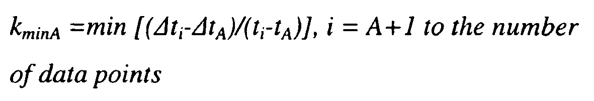
- 4. From (A) to the message delay data point (B), which corresponds to kminA, calculate the
distance 1A from the data point (A) to the new data point (B):
- 5. If lA 2 > l1 2 , then kminA is the best approximation; otherwise, kmin1 is the best approximation so far.
- 6. From data point (B), repeat steps 3 to 6 until all data points in the set have been evaluated.
- In essence, the minimum delay algorithm determines the two minimum delay values that have the longest distance between them. The line is then fitted to intersect those two points. This algorithm is well-suited for evaluating statistical distributions like the one depicted in
Fig. 6 . In contrast, least-squares algorithms essentially assume Gaussian (symmetrical) distributions and do not apply any filtering to discard outliers in the data set. - A drawback of the minimum delay algorithm is that its accuracy is only as good is the two selected minimum delay points. Better accuracy may be achieved if more than two minimum delay points are used, e.g., by means of minimum delay procedures that employ different weights. Instead of only two contact points, a weighted average of kmm,i can be used weighted with li; , li;2 or li 4 for example:


- A second and preferred line-fitting algorithm that also provides better resilience to individual errors in the data points is a combination of the minimum delay algorithm and the least squares algorithm called the "hybrid" algorithm. The hybrid algorithm divides the integration time into a number of intervals and fits a line to the minimum delay value in each interval as depicted in
Fig. 13 . More intervals mean more data points for the fitting process, which limits the impact of errors in one or more data points on the final result. - Although any number of intervals may be used, it is preferable to determine an optimal number of timestamp delay values to be included in each interval. If the intervals include too few timestamps, the minimum delay value in each interval will not be an accurate minimum value. On the other hand, if too many timestamps are included, the minimum value will not be accurate because the effect of the drift (the slope) will dominate. In other words, the minimum delay values will probably be found in the beginning of an interval (in case of a positive slope) or towards the end of the interval for a negative slope if too many timestamps are included. This artifact introduces an error that can be controlled by limiting the number of timestamps.
- An analytical expression for the optimal number of timestamps is set forth below. As seen from Eq. (30), the optimal number of timestamps depends on the number and periodicity of the timestamps, the frequency drift, and the magnitude of packet jitter. In order to optimize the number of timestamps, we try to find a minimum variance of the least squares slope σb 2 which can be expressed as


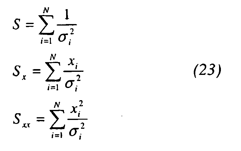
Fig. 13 .ssume the following: - There are n data points available in total.
- There are m data points in each interval and is the parameter to which σb should be optimized.
- xi; is assumed to be rather periodical, i.e., timestamps are sent more or less periodically.
- tj is this packet jitter and T is the total experimental time
- Using the above, we may write

- Let us now make two assumptions regarding σi: It is the same for all delay points (σx), and it is decreasing with the number of delay points in the interval:

Fig. 7 . - The effect of drift on the standard deviation may be approximated as 1/2·ρ·(m/n)·T, which results in:


- Using Eqs. (24), (27), (29) and minimizing σb 2 with respect to m by taking the derivative dσb 2/dm = 0, one obtains an expression for the optimum number of data points in each interval m:


- The optimal number of timestamps depends on several factors including drift, jitter, time between timestamps, and number of timestamps.
Fig. 14 shows σb 2 versus m/n for the case of 40 timestamps, 30 ms jitter, 32 s between timestamps, and 20 ppb drift. The optimum number of timestamps in each interval is approximately 12%, corresponding to 4 timestamps in each interval. -
Fig. 15 shows simulated convergence abilities of various line fitting algorithms versus number of timestamps (or seconds--timestamps are sent every second in this case). The dotted line corresponds to a least-squares algorithm. The thick line corresponds to the minimum delay algorithm, and the thin line corresponds to the hybrid optimal algorithm. Even after 80 timestamps, the least-squares algorithm does not reach a 30 ppb synchronization window. The minimum delay and hybrid optimal algorithms are both much faster, reaching a 30 ppb window within 20 to 30 timestamps. This kind of convergence speed is important for certain synchronization applications. One example is cold start, RBS frequency synchronization which needs to be achieved in approximately 5 to 10 minutes. - Synchronization in accordance with various features of the invention provides many benefits. Both frequency and absolute time synchronization may be achieved. The packet-switched network intermediate nodes need not be changed. When comparing equal amount of timestamp traffic, synchronization is achieved much faster compared to other synchronization algorithms. Timestamp periodicity is not required which facilitates increased timestamp traffic thereby speeding up the synchronization process even further. It is possible to reach 50 ppb accuracy within a few minutes with this method making it possible to cold start an RBS using this synchronization scheme. Packet loss is not a problem, and a standard master-client configuration is readily supported, as well as broadcast/multicast configurations. The preferred use is in a decentralized configuration, but the synchronization procedure can also be used in centralized configurations such as NodeSync over the Iub interface in a UMTS type communications network. Further, the roundtrip embodiment is resilient to network congestion effects since the frequency drift can be estimated in two independent ways so that artifacts can be easily sorted out. The invention may be applied to any packet-switched, asynchronous network, non-limiting examples being Ethernet, ATM, IP, etc.
- While the invention has been described in connection with what is presently considered to be the most practical and preferred embodiments, the invention is not limited to the disclosed embodiments. Rather the invention covers various modifications and equivalent arrangements included within the scope of the appended claims.
Claims (41)
- A communications system (10) comprising a first node (16), having a first oscillator (32), for sending multiple messages over a network and including or associating with each message a first timestamp corresponding to a time when the first node (16) sent that message, and a second node (12), having a second oscillator (20), for receiving each message and including or associating with that message a second timestamp corresponding to a time when the second node (12) received that message, characterized by:one of the first and second nodes being configured to determine for each message a first time difference between the corresponding first and second timestamps, and from multiple first time differences, to fit a line to an optimal variable number of minimum delay values of the first time differences, a characteristic of the line being related to a frequency drift between the first and second oscillators,wherein the one node is configured to determine the optimal variable number depending on the number and periodicity of the timestamps, the frequency drift, and the magnitude of message jitter, andwherein the one node is configured to determine from the line a frequency adjustment to synchronize the first and second oscillators (32, 20).
- The system in claim 1, wherein the first node is configured to adjust the first oscillator using the frequency adjustment.
- The system in claim 1, wherein the first node is configured to send a message to the second node to adjust the second oscillator using the frequency adjustment.
- The system in claim 1, wherein the one node is the second node configured to adjust the second oscillator using the frequency adjustment.
- The system in claim 1, further comprising:plural second nodes,wherein the first node and the second nodes are configured so that the first node synchronizes the second nodes by broadcasting the frequency adjustment to the second nodes.
- The system in claim 1, wherein the one node is the first node configured to send a message to the second node that includes the frequency adjustment for adjusting the second oscillator.
- The system in claim 1, wherein the first node (16) is a timeserver and the second node (12) is a client node and the messages are transported over a packet-switched network.
- The system in claim 1, wherein the system is a mobile communications system, the first node is a radio network controller, and the second node is a radio base station.
- The system in claim 1, wherein the system is a mobile communications system, the first node is a radio base station, and the second node is a radio network controller.
- The system in claim 1, wherein the characteristic of the line is a slope ρ of the line and the one node is configured to adjust the second oscillator by a factor of 1- p.
- The system in claim 1, wherein the one node is configured to determine an equation of a line that intersects the two minimum first time difference values.
- The system in claim 11, wherein the one node is configured to determine the two minimum first time difference values from the multiple time differences that are farthest apart.
- The system in claim 1, where the optimization is a tradeoff between too few timestamps, which results in a less accurate minimum values, and too many timestamps which will deteriorate accuracy because the effect of the drift.
- The system in claim 1, wherein the one node is configured to divide the first time differences into an optimal number of time slots, determine a minimum time difference value for each time interval, fit the line to intersect a minimum time difference value for each time interval, and determine a minimum number of time difference values for each time interval.
- The communications system in claim 1, wherein the first node (16) includes a first timer (34), and
the second node (12) includes a second timer (22) for including or associating with each message a third timestamp corresponding to a time when the second node sends that message back to the first node (16),
wherein the first node (16) is configured to include or associate with each received message a fourth timestamp corresponding to a time when the first node (16) received that message,
wherein one of the first and second nodes is configured to determine for each received message a second time difference between the corresponding third and fourth timestamps, and from multiple sets of first and second time differences, to determine a minimum first time difference and a minimum second time difference, and
wherein the one node is configured to determine from one or both of the minimum first and second time differences one or both of (1) a frequency adjustment to synchronize the first and second oscillators (32, 20), and (2) a time adjustment to synchronize the first and second timers (34, 22). - The system in claim 15, wherein the first node (16) is configured to adjust the first oscillator (32) to be synchronized with the second oscillator (20).
- The system in claim 15, wherein the first node (16) is configured to adjust the first timer (34) to be synchronized with the second timer (22).
- The system in claim 15, wherein the first node (16) is configured to send an adjustment message to the second node (12) to adjust one or both of the second oscillator (20) and the second timer (22).
- The system in claim 15, wherein the first node (16) is configured to determine two minimum first time differences that are farthest apart in the multiple sets of first time differences and two minimum second time differences that are farthest apart in the multiple sets of second time differences.
- The system in claim 19, wherein the one node is configured to determine a first line that fits the two minimum first time differences and a second line that fits the two minimum second time differences, and from the first and second lines, to determine one or both of the frequency adjustment and the time adjustment.
- The system in claim 20, wherein the one node is configured to determine an equation of each of the first and second lines and to use a first slope and a first vertical axis intercept of the first line and a second slope and a second vertical axis intercept of the second line to determine one or both of the frequency adjustment and the time adjustment.
- The system in claim 21, wherein the one node is configured to determine whether the first slope and the second slope have approximately the same magnitude and whether one of the first and second slopes is positive and the other is negative.
- The system in claim 15, wherein the one node is configured to determine an optimal number of minimum values of the first time differences to be used in fitting the line to the multiple values of the first time differences.
- The system in claim 23, wherein the one node is configured to divide multiple values of the first time differences into an optimal number of time slots and determine minimum time difference values for each time interval and fit the line to intersect a minimum time difference value for each time interval.
- The system in claim 24, wherein the one node is configured to determine a minimum number of time difference values for each time interval.
- A method for use in a communications system (10) including a first node (16) having a first oscillator (32) and a second node (12) having a second oscillator (20), comprising the first node (16) sending multiple messages over a network (14) and including or associating with each message a first timestamp corresponding to a time when the first node (16) sent that message, and the second node (12) receiving each message and including or associating with that message a second timestamp corresponding to a time when the second node (12) received that message, the method characterized by:determining for each message a first time difference between the corresponding first and second timestamps, and from multiple first time differences, fitting a line to an optimal variable number of minimum values of the first time differences, a characteristic of the line being related to a frequency drift between the first and second oscillators,wherein the optimal variable number is determined depending on the number and periodicity of the timestamps, the frequency drift, and the magnitude of message jitter, anddetermining from the line a frequency adjustment to synchronize the first and second oscillators.
- The method in claim 26, wherein the characteristic of the line is a slope p of the line.
- The method in claim 27, wherein the frequency adjustment is related to (1- ρ).
- The method in claim 26, further comprising:determining an equation of a line that intersects the two minimum time difference values, anddetermining the two minimum time difference values that are farthest apart.
- The method in claim 26, further comprising:determining an optimal number of minimum values of the first time differences to be used in fitting the line;dividing multiple values of the first time differences into an optimal number of time slots;determining a minimum time difference value for each time interval; andfitting the line to intersect a minimum time difference value for each time interval.
- A node (12, 16) for use in a communications system, comprising a first oscillator (20 or 32), a controller (18 or 30) for receiving multiple messages from another node (16 or 12) over a network (14), each message having a first timestamp corresponding to a time when the first node sent that message, and for including or associating with that message a second timestamp corresponding to a time when the other node received that message, characterized by:the controller being configured to (1) determine for each message a first time difference between the corresponding first and second timestamps, and from multiple first time differences, fit a line to an optimal variable number of minimum values of the first time differences, a characteristic of the line being related to a frequency drift between the first and second oscillators,wherein the controller is further configured to determine the optimal variable number depending on the number and periodicity of the timestamps, the frequency drift, and the magnitude of message jitter, and (2) determine from the line a frequency adjustment to synchronize the first oscillator with a second oscillator in the other node.
- The node in claim 31, wherein the characteristic of the line is a slope p of the line.
- The method in claim 32, wherein the frequency adjustment is related to (1-ρ).
- The node in claim 31, wherein the controller is further configured to:determine an equation of a line that intersects the two minimum time difference values, anddetermine the two minimum time difference values that are farthest apart.
- The node in claim 31, wherein the controller is further configured to:determine an optimal number of minimum values of the first time differences to be used in fitting the line;divide multiple values of the first time differences into an optimal number of time slots;determine a minimum time difference value for each time interval; andfit the line to intersect a minimum time difference value for each time interval; anddetermine a minimum number of time difference values for each time interval.
- The node in claim 31, wherein the node is a timeserver (16) and the other node (12) is a client node and the messages are transported over a packet-switched network (14).
- The node in claim 31, wherein the communications system is a mobile communications system, the node is one of a radio network controller and a radio base station and the other node is the other of the radio network controller and the radio base station.
- The node in claim 31, further comprising:first timer (34 or 22);wherein the controller is further configured to:include or associate with the message a third timestamp corresponding to a time when the node sends that message back to the other node which includes or associates with each received message a fourth timestamp corresponding to a time when the other node received that message;determine for each received message a second time difference between the corresponding third and fourth timestamps, and from multiple sets of first and second time differences, determines a minimum first time difference and a minimum second time difference, and determines from one or both of the minimum first and second time differences one or both of (1) a frequency adjustment to synchronize the first and second oscillators and (2) a time adjustment to synchronize the first timer and a second timer associated with the other node.
- The node in claim 38, wherein the controller is further configured to:determine a first line that fits the multiple sets of first time differences and a second line that fits the multiple sets of second time differences, andfrom the first and second lines, determine one or both of the frequency adjustment and the time adjustment.
- The node in claim 39, wherein the controller is further configured to:fit the first and second lines to the first and second sets of time differences by identifying at least two minimum time difference points for each set and determining an equation of a line that intersects the two minimum delay time difference points.
- The node in claim 40, wherein the controller is further configured to:determine the two minimum time difference points farthest apart in each of the first and second sets;use a first slope and a first vertical axis intercept of the first line and a second slope and a second vertical axis intercept of the second line to determine the first and second minimum time differences; anddetermine whether the first slope and the second slope have approximately the same magnitude and whether one of the first and second slopes is positive and the other is negative.
Applications Claiming Priority (2)
| Application Number | Priority Date | Filing Date | Title |
|---|---|---|---|
| US10/645,837 US7415044B2 (en) | 2003-08-22 | 2003-08-22 | Remote synchronization in packet-switched networks |
| PCT/SE2004/001150 WO2005020486A1 (en) | 2003-08-22 | 2004-07-22 | Remote synchronization in packet-switched networks |
Publications (2)
| Publication Number | Publication Date |
|---|---|
| EP1656754A1 EP1656754A1 (en) | 2006-05-17 |
| EP1656754B1 true EP1656754B1 (en) | 2012-01-11 |
Family
ID=34194398
Family Applications (1)
| Application Number | Title | Priority Date | Filing Date |
|---|---|---|---|
| EP04749186A Not-in-force EP1656754B1 (en) | 2003-08-22 | 2004-07-22 | Remote synchronization in packet-switched networks |
Country Status (5)
| Country | Link |
|---|---|
| US (1) | US7415044B2 (en) |
| EP (1) | EP1656754B1 (en) |
| CN (1) | CN1839573B (en) |
| AT (1) | ATE541369T1 (en) |
| WO (1) | WO2005020486A1 (en) |
Families Citing this family (102)
| Publication number | Priority date | Publication date | Assignee | Title |
|---|---|---|---|---|
| US7013308B1 (en) | 2000-11-28 | 2006-03-14 | Semscript Ltd. | Knowledge storage and retrieval system and method |
| SE0004839D0 (en) * | 2000-12-22 | 2000-12-22 | Ericsson Telefon Ab L M | Method and communication apparatus in a communication system |
| DE10331313B3 (en) * | 2003-07-10 | 2005-01-05 | Siemens Ag | Method for synchronizing a radio communication system divided into radio cells |
| US7602815B2 (en) * | 2003-09-04 | 2009-10-13 | Broadcom Corporation | Using network time protocol in voice over packet transmission |
| US7768931B2 (en) * | 2004-10-07 | 2010-08-03 | Westerngeco L.L.C. | Hardware-based network packet timestamps: improved network clock synchronization |
| US7970020B2 (en) * | 2004-10-27 | 2011-06-28 | Telefonaktiebolaget Lm Ericsson (Publ) | Terminal having plural playback pointers for jitter buffer |
| US7620137B2 (en) * | 2004-11-13 | 2009-11-17 | Microsoft Corporation | System and method for clock drift correction for broadcast audio/video streaming |
| US8270301B2 (en) * | 2004-12-29 | 2012-09-18 | Alcatel Lucent | Delay distributed virtually-concatenated data traffic |
| CN1320788C (en) * | 2005-03-22 | 2007-06-06 | 展讯通信(上海)有限公司 | A time synchronization method for TD-SCDMA system |
| FI119164B (en) * | 2005-04-08 | 2008-08-15 | Tellabs Oy | Method and apparatus for regenerating a timing signal in digital communication |
| US8228956B2 (en) * | 2005-04-19 | 2012-07-24 | Alcatel Lucent | Time stamp offset in data packet bundling |
| FR2886793A1 (en) * | 2005-06-06 | 2006-12-08 | France Telecom | METHOD AND SYSTEM FOR TRANSMITTING A SYNCHRONIZATION RHYTHM ON A NETWORK LINK OF ETHERNET TECHNOLOGY AND THEIR APPLICATIONS |
| US8666928B2 (en) | 2005-08-01 | 2014-03-04 | Evi Technologies Limited | Knowledge repository |
| CN100459529C (en) * | 2005-09-12 | 2009-02-04 | 华为技术有限公司 | Time delay characteristic measuring method in data communication network |
| EP1785802A1 (en) * | 2005-11-10 | 2007-05-16 | ETH Zürich, ETH Transfer | Method for frequency synchronization |
| CN101310462B (en) * | 2005-11-14 | 2013-01-02 | 艾利森电话股份有限公司 | Generating clock signal on basis of received packet stream |
| JP4714595B2 (en) * | 2006-01-31 | 2011-06-29 | リョービ株式会社 | Overlay detection device |
| US20070177572A1 (en) * | 2006-01-31 | 2007-08-02 | Werenka Leon K | Method and system for reporting synchronization status in a network of RF receivers |
| US8064484B2 (en) * | 2006-02-01 | 2011-11-22 | Symmetricom, Inc. | Enhanced clock control in packet networks |
| US7801997B2 (en) * | 2006-03-30 | 2010-09-21 | International Business Machines Corporation | Asynchronous interconnect protocol for a clustered DBMS |
| WO2007120089A1 (en) * | 2006-04-13 | 2007-10-25 | Telefonaktiebolaget Lm Ericsson (Publ) | Network synchronisation supervision |
| GB2441372A (en) * | 2006-08-29 | 2008-03-05 | Ubiquisys Ltd | Syncronising basestations |
| FI119165B (en) | 2006-12-04 | 2008-08-15 | Tellabs Oy | Procedure and system for synchronizing clock signals |
| CN101247169A (en) * | 2007-02-15 | 2008-08-20 | 华为技术有限公司 | Method, system and equipment for implementing time synchronization in communication network |
| US8923141B2 (en) * | 2007-03-16 | 2014-12-30 | Cisco Technology, Inc. | Providing clock synchronization in a network |
| FI121770B (en) | 2007-05-28 | 2011-03-31 | Tellabs Oy | Method and apparatus for transmitting synchronization information |
| FI120284B (en) * | 2007-07-20 | 2009-08-31 | Tellabs Oy | Control of the fill rate in a jitter buffer |
| EP2026485A1 (en) * | 2007-08-17 | 2009-02-18 | Nokia Siemens Networks Oy | Method and device for a packet based clock recovery |
| CN101119157B (en) * | 2007-09-18 | 2011-09-21 | 中兴通讯股份有限公司 | Method and system for measuring optical fibre time delay |
| US8838659B2 (en) * | 2007-10-04 | 2014-09-16 | Amazon Technologies, Inc. | Enhanced knowledge repository |
| US20090097452A1 (en) * | 2007-10-12 | 2009-04-16 | Qualcomm Incorporated | Femto cell synchronization and pilot search methodology |
| FI120378B (en) | 2007-10-24 | 2009-09-30 | Tellabs Oy | Procedure and arrangement for transferring the value of the time of day between network elements |
| WO2009066376A1 (en) * | 2007-11-21 | 2009-05-28 | Fujitsu Limited | Communication device, base station device, data reception timing synchronization method |
| GB2454936B (en) * | 2007-11-23 | 2012-09-19 | Ubiquisys Ltd | Oscillator calibration |
| JP4592743B2 (en) * | 2007-12-28 | 2010-12-08 | 古野電気株式会社 | Synchronization device and synchronization method |
| FR2927208B1 (en) * | 2008-01-31 | 2010-02-12 | Airbus France | METHOD AND DEVICE FOR MEASURING THE TEMPORAL DERIVATIVE OF AN ELECTRONIC EQUIPMENT CONNECTED TO A NETWORK |
| CA2717591C (en) * | 2008-02-19 | 2016-11-08 | Elbit Systems Of America, Llc | Mimo slotted aloha (msa) system |
| AU2014200874B2 (en) * | 2008-02-19 | 2015-10-08 | Innovative Concepts, Inc. | Mimo slotted aloha (msa) system |
| FI122945B (en) * | 2008-05-30 | 2012-09-14 | Tellabs Oy | Procedure and equipment for measurements |
| JP5051056B2 (en) * | 2008-08-13 | 2012-10-17 | 富士通株式会社 | Communications system |
| GB0815458D0 (en) * | 2008-08-26 | 2008-10-01 | Zarlink Semiconductor Inc | Method of transferring timing information over packet network |
| WO2010025743A1 (en) | 2008-09-02 | 2010-03-11 | Siemens Enterprise Communications Gmbh & Co. Kg | A method for synchronizing clocks in a communication network |
| CN101674174B (en) * | 2008-09-12 | 2013-06-05 | 华为技术有限公司 | Method and equipment for increasing clock stability |
| WO2010041852A2 (en) * | 2008-10-06 | 2010-04-15 | Noh Sam Hyuk | Method and system for perpetual computing using non-volatile random access memory (nvram) |
| WO2010045961A1 (en) * | 2008-10-24 | 2010-04-29 | Telefonaktiebolaget Lm Ericsson (Publ) | Method and device for packet network synchronization |
| US8416763B1 (en) | 2008-11-14 | 2013-04-09 | Cisco Technology, Inc. | System and method for providing quality inter-domain network time transport |
| US9805089B2 (en) | 2009-02-10 | 2017-10-31 | Amazon Technologies, Inc. | Local business and product search system and method |
| JP5369814B2 (en) * | 2009-03-26 | 2013-12-18 | ソニー株式会社 | Receiving device and time correction method for receiving device |
| US8031747B2 (en) * | 2009-04-29 | 2011-10-04 | Juniper Networks, Inc. | Apparatus and method of compensating for clock frequency and phase variations by processing packet delay values |
| GB0908884D0 (en) * | 2009-05-22 | 2009-07-01 | Zarlink Semiconductor Inc | Time recovery over packet networks |
| EP2282427B1 (en) * | 2009-07-31 | 2015-03-04 | Alcatel Lucent | Method for synchronizing a client clock frequency with a server clock frequency |
| CN102025480A (en) * | 2009-09-14 | 2011-04-20 | 中兴通讯股份有限公司 | Method and device for realizing boundary clock in cascade base station |
| US8385212B2 (en) * | 2009-12-07 | 2013-02-26 | Symmetricom, Inc. | Method and apparatus for finding latency floor in packet networks |
| US8340010B2 (en) * | 2009-12-16 | 2012-12-25 | Broadcom Corporation | Method and system for energy efficient synchronization in packet based networks |
| US8462819B2 (en) * | 2010-01-06 | 2013-06-11 | Lsi Corporation | Adaptive clock recovery with step-delay pre-compensation |
| US8411705B2 (en) | 2010-01-06 | 2013-04-02 | Lsi Corporation | Three-stage architecture for adaptive clock recovery |
| US8135866B2 (en) | 2010-01-22 | 2012-03-13 | Research In Motion Limited | System and method for detecting and processing stale messages |
| GB201002401D0 (en) * | 2010-02-12 | 2010-03-31 | Zarlink Semiconductor Inc | Feedforward synchronization in asynchronous packet networks |
| US8654758B2 (en) | 2010-04-16 | 2014-02-18 | Simmonds Precision Products, Inc. | Synchronization within wireless devices |
| US8660110B2 (en) | 2010-04-16 | 2014-02-25 | Simmonds Precision Products, Inc. | Reduced power synchronization of wireless devices |
| US8406217B2 (en) * | 2010-04-16 | 2013-03-26 | Simmonds Precision Products, Inc. | Synchronizing wireless devices using timestamps and relative clock offsets of the wireless devices |
| US8401025B2 (en) | 2010-04-28 | 2013-03-19 | Lsi Corporation | Windowing technique for adaptive clock recovery and other signal-processing applications |
| US9110882B2 (en) | 2010-05-14 | 2015-08-18 | Amazon Technologies, Inc. | Extracting structured knowledge from unstructured text |
| WO2012148321A1 (en) * | 2011-04-26 | 2012-11-01 | Telefonaktiebolaget L M Ericsson (Publ) | Base station synchronization |
| EP2568632B1 (en) * | 2011-09-09 | 2020-09-16 | Simmonds Precision Products, Inc. | Synchronization within wireless devices |
| US8885558B2 (en) * | 2011-09-28 | 2014-11-11 | Robert Bosch Gmbh | System and method for multiple access sensor networks |
| CN103329603A (en) * | 2011-11-15 | 2013-09-25 | 戴卡维夫有限公司 | A wireless access point clock synchronization system |
| CN102412954B (en) * | 2011-11-19 | 2014-10-22 | 西安邮电学院 | Clock frequency synchronization method in packet based network |
| US9697159B2 (en) * | 2011-12-27 | 2017-07-04 | Intel Corporation | Multi-protocol I/O interconnect time synchronization |
| FI20125742A (en) | 2012-06-28 | 2013-12-29 | Tellabs Oy | Method and apparatus for controlling a clock signal source |
| DE102012214125A1 (en) * | 2012-08-09 | 2014-02-13 | Siemens Aktiengesellschaft | Transmission of an event signal |
| KR101974899B1 (en) * | 2012-10-23 | 2019-05-03 | 삼성전자주식회사 | Method and apparatus for synchronizing device-to-device communications |
| US9395697B2 (en) * | 2012-10-26 | 2016-07-19 | Qualcomm Technologies International, Ltd. | Method and apparatus for calculating transmission delay across a network |
| CN102916759B (en) * | 2012-10-26 | 2015-05-13 | 郑州威科姆科技股份有限公司 | Method for calibrating E1 data frame precision time and processing time mark information |
| CN103857029B (en) * | 2012-11-30 | 2017-04-05 | 上海贝尔股份有限公司 | A kind of method of the delay inequality for determining up-link and downlink, device and equipment |
| US8954546B2 (en) | 2013-01-25 | 2015-02-10 | Concurix Corporation | Tracing with a workload distributor |
| US8997063B2 (en) | 2013-02-12 | 2015-03-31 | Concurix Corporation | Periodicity optimization in an automated tracing system |
| US8924941B2 (en) | 2013-02-12 | 2014-12-30 | Concurix Corporation | Optimization analysis using similar frequencies |
| US20130283281A1 (en) | 2013-02-12 | 2013-10-24 | Concurix Corporation | Deploying Trace Objectives using Cost Analyses |
| US9665474B2 (en) * | 2013-03-15 | 2017-05-30 | Microsoft Technology Licensing, Llc | Relationships derived from trace data |
| US9575874B2 (en) | 2013-04-20 | 2017-02-21 | Microsoft Technology Licensing, Llc | Error list and bug report analysis for configuring an application tracer |
| CN103259640B (en) * | 2013-05-28 | 2016-08-31 | 杭州华三通信技术有限公司 | A kind of method and apparatus of lock in time |
| JP2014238357A (en) * | 2013-06-10 | 2014-12-18 | ソニー株式会社 | Reception device, time difference calculation method and program |
| CN103607267B (en) * | 2013-07-23 | 2019-03-15 | 王健 | The end-to-end propagation delay time of data network message is with band measurement method |
| US9292415B2 (en) | 2013-09-04 | 2016-03-22 | Microsoft Technology Licensing, Llc | Module specific tracing in a shared module environment |
| US9184861B2 (en) * | 2013-10-01 | 2015-11-10 | Khalifa University of Science, Technology, and Research | Method and devices for synchronization |
| EP3053289B1 (en) * | 2013-10-02 | 2019-12-18 | Khalifa University of Science and Technology | Method and devices for compensating for path asymmetry |
| US9112628B2 (en) * | 2013-10-02 | 2015-08-18 | Khalifa University of Science, Technology, and Research | Method and devices for compensating for path asymmetry |
| EP3066878B1 (en) * | 2013-11-10 | 2018-08-15 | Telefonaktiebolaget LM Ericsson (publ) | Over-the-air frequency and time synchronization for small cells |
| WO2015071778A1 (en) | 2013-11-13 | 2015-05-21 | Concurix Corporation | Application execution path tracing with configurable origin definition |
| KR102278867B1 (en) * | 2014-12-16 | 2021-07-21 | 로베르트 보쉬 게엠베하 | Method of synchronising clocks of network devices |
| US9555883B1 (en) | 2015-06-25 | 2017-01-31 | Amazon Technologies, Inc. | Unmanned aerial vehicle sensor synchronization |
| US10148412B1 (en) * | 2015-06-25 | 2018-12-04 | Marvell International Ltd. | Methods and apparatus for clock drift mitigation |
| CN105119775A (en) * | 2015-08-28 | 2015-12-02 | 国电南瑞科技股份有限公司 | Method for improving accuracy of Ethernet message transmission delay measurement |
| JP2017175203A (en) * | 2016-03-18 | 2017-09-28 | セイコーエプソン株式会社 | Oscillator, electronic apparatus, and movable body |
| CN110278049B (en) * | 2019-07-08 | 2021-03-30 | 贵州省计量测试院 | Time synchronization method and system |
| JP6672511B1 (en) * | 2019-07-09 | 2020-03-25 | 株式会社東芝 | Sensor system, transmission terminal, time information processing device, and synchronization method |
| US11593162B2 (en) * | 2020-10-20 | 2023-02-28 | EMC IP Holding Company LLC | Techniques for scheduling between applications on a core |
| KR20220149724A (en) * | 2020-12-17 | 2022-11-08 | 미쓰비시덴키 가부시키가이샤 | Control device, image recording method and recording medium |
| SE545648C2 (en) * | 2021-10-01 | 2023-11-21 | Net Insight Ab | Dynamic traffic load compensation |
| IL290209A (en) * | 2022-01-26 | 2024-02-01 | Rafael Advanced Defense Systems Ltd | Frequency Synchronization in Decentralized Communication Networks |
| WO2023164301A2 (en) * | 2022-02-28 | 2023-08-31 | Arris Enterprises Llc | Method of measuring timing holdover performance in an r-phy system |
Family Cites Families (62)
| Publication number | Priority date | Publication date | Assignee | Title |
|---|---|---|---|---|
| EP0596651A1 (en) | 1992-11-02 | 1994-05-11 | National Semiconductor Corporation | Network for data communication with isochronous capability |
| EP0596648A1 (en) | 1992-11-02 | 1994-05-11 | National Semiconductor Corporation | Network link endpoint capability detection |
| US5544324A (en) | 1992-11-02 | 1996-08-06 | National Semiconductor Corporation | Network for transmitting isochronous-source data using a frame structure with variable number of time slots to compensate for timing variance between reference clock and data rate |
| US5450410A (en) | 1993-09-17 | 1995-09-12 | Motorola, Inc. | Method and apparatus for constant bit rate traffic in fast packet networks |
| US5553071A (en) | 1994-10-14 | 1996-09-03 | Lucent Technologies Inc. | Communication system topology providing dynamic allocation of B-channels |
| US5862343A (en) | 1995-02-10 | 1999-01-19 | National Semiconductor Corporation | Circuit for logical stream sorting at CPU transfer time division for multiplexed (TDM) including bus interface circuitry |
| EP0769228B1 (en) | 1995-02-10 | 2003-04-02 | National Semiconductor Corporation | Method for transmitting data isochronously at a rate less than the isochronous data rate |
| US5594732A (en) | 1995-03-03 | 1997-01-14 | Intecom, Incorporated | Bridging and signalling subsystems and methods for private and hybrid communications systems including multimedia systems |
| US5805597A (en) | 1996-06-04 | 1998-09-08 | National Semiconductor Corporation | Method and apparatus for providing low power basic telephony type service over a twisted pair ethernet physical layer |
| US6064673A (en) | 1996-08-02 | 2000-05-16 | 3Com Corporation | Communications system having distributed control and real-time bandwidth management |
| US6335927B1 (en) | 1996-11-18 | 2002-01-01 | Mci Communications Corporation | System and method for providing requested quality of service in a hybrid network |
| US5999525A (en) | 1996-11-18 | 1999-12-07 | Mci Communications Corporation | Method for video telephony over a hybrid network |
| GB2320642A (en) | 1996-12-21 | 1998-06-24 | Ibm | Distributed voice processing system |
| US6360271B1 (en) | 1999-02-02 | 2002-03-19 | 3Com Corporation | System for dynamic jitter buffer management based on synchronized clocks |
| US6434606B1 (en) | 1997-10-01 | 2002-08-13 | 3Com Corporation | System for real time communication buffer management |
| US6215797B1 (en) | 1998-08-19 | 2001-04-10 | Path 1 Technologies, Inc. | Methods and apparatus for providing quality of service guarantees in computer networks |
| US6246702B1 (en) | 1998-08-19 | 2001-06-12 | Path 1 Network Technologies, Inc. | Methods and apparatus for providing quality-of-service guarantees in computer networks |
| US6327274B1 (en) | 1998-09-15 | 2001-12-04 | Nokia Telecommunications, Inc. | Method for estimating relative skew between clocks in packet networks |
| SE513899C2 (en) | 1999-01-12 | 2000-11-20 | Ericsson Telefon Ab L M | Method and arrangement for synchronization |
| EP1032165A1 (en) | 1999-02-26 | 2000-08-30 | International Business Machines Corporation | Method of assembling segmented frames of data transmitted over a backbone |
| US20020101885A1 (en) | 1999-03-15 | 2002-08-01 | Vladimir Pogrebinsky | Jitter buffer and methods for control of same |
| US6661810B1 (en) | 1999-03-19 | 2003-12-09 | Verizon Laboratories Inc. | Clock skew estimation and removal |
| US6658027B1 (en) | 1999-08-16 | 2003-12-02 | Nortel Networks Limited | Jitter buffer management |
| FI115494B (en) * | 1999-09-08 | 2005-05-13 | Nokia Corp | Base station frequency synchronization |
| DE19943790C2 (en) | 1999-09-13 | 2001-11-15 | Ericsson Telefon Ab L M | Method and device for determining a synchronization error in a network node |
| US6747999B1 (en) | 1999-11-15 | 2004-06-08 | Siemens Information And Communication Networks, Inc. | Jitter buffer adjustment algorithm |
| US20020075857A1 (en) | 1999-12-09 | 2002-06-20 | Leblanc Wilfrid | Jitter buffer and lost-frame-recovery interworking |
| US6438702B1 (en) | 1999-12-21 | 2002-08-20 | Telcordia Technologies, Inc. | Method for providing a precise network time service |
| US7103124B1 (en) | 1999-12-30 | 2006-09-05 | Telefonaktiebolaget Lm Ericsson (Publ) | Synchronization of nodes |
| FI108489B (en) | 1999-12-30 | 2002-01-31 | Nokia Corp | Synchronization in a packet-switched communication system |
| ATE349113T1 (en) | 2000-04-14 | 2007-01-15 | Cit Alcatel | SELF-ADJUSTABLE SHIMMER BUFFER MEMORY |
| US6577872B1 (en) | 2000-08-08 | 2003-06-10 | Telefonaktiebolaget Lm Ericsson (Publ) | Base station oscillator regulation independent of transport network clocks in cellular telecommunications network |
| KR100358382B1 (en) | 2000-08-28 | 2002-10-25 | 엘지전자 주식회사 | Apparatus for parallel mapping of serial input data in SDH system |
| US6928473B1 (en) * | 2000-09-26 | 2005-08-09 | Microsoft Corporation | Measuring network jitter on application packet flows |
| US7546376B2 (en) | 2000-11-06 | 2009-06-09 | Telefonaktiebolaget Lm Ericsson (Publ) | Media binding to coordinate quality of service requirements for media flows in a multimedia session with IP bearer resources |
| US7023816B2 (en) | 2000-12-13 | 2006-04-04 | Safenet, Inc. | Method and system for time synchronization |
| SE0004839D0 (en) | 2000-12-22 | 2000-12-22 | Ericsson Telefon Ab L M | Method and communication apparatus in a communication system |
| NO20006684D0 (en) | 2000-12-28 | 2000-12-28 | Abb Research Ltd | Time Synchronization |
| US20020172229A1 (en) | 2001-03-16 | 2002-11-21 | Kenetec, Inc. | Method and apparatus for transporting a synchronous or plesiochronous signal over a packet network |
| ES2280370T3 (en) | 2001-04-24 | 2007-09-16 | Nokia Corporation | METHODS TO CHANGE THE SIZE OF AN INTERMEDIATE FLUCTUATION MEMORY AND FOR TEMPORARY ALIGNMENT, A COMMUNICATION SYSTEM, AN EXTREME RECEIVER, AND A TRANSCODER. |
| CA2347927A1 (en) | 2001-05-16 | 2002-11-16 | Telecommunications Research Laboratories | Centralized synchronization for wireless networks |
| US7697447B2 (en) | 2001-08-10 | 2010-04-13 | Motorola Inc. | Control of jitter buffer size and depth |
| US20030112758A1 (en) | 2001-12-03 | 2003-06-19 | Pang Jon Laurent | Methods and systems for managing variable delays in packet transmission |
| US7266127B2 (en) | 2002-02-08 | 2007-09-04 | Lucent Technologies Inc. | Method and system to compensate for the effects of packet delays on speech quality in a Voice-over IP system |
| US7079486B2 (en) | 2002-02-13 | 2006-07-18 | Agere Systems Inc. | Adaptive threshold based jitter buffer management for packetized data |
| US7263109B2 (en) | 2002-03-11 | 2007-08-28 | Conexant, Inc. | Clock skew compensation for a jitter buffer |
| ES2223986T3 (en) | 2002-03-28 | 2005-03-01 | Siemens Schweiz Ag | PROCEDURE FOR ADJUSTMENT OF AN UNSTABLE INTERMEDIATE MEMORY IN AN INTERNATIONAL MEDIA ACCESS CENTER. |
| US7496086B2 (en) | 2002-04-30 | 2009-02-24 | Alcatel-Lucent Usa Inc. | Techniques for jitter buffer delay management |
| US7336678B2 (en) | 2002-07-31 | 2008-02-26 | Intel Corporation | State-based jitter buffer and method of operation |
| US6985459B2 (en) | 2002-08-21 | 2006-01-10 | Qualcomm Incorporated | Early transmission and playout of packets in wireless communication systems |
| US7130368B1 (en) * | 2002-09-19 | 2006-10-31 | Nortel Network Limited | Clock recovery using a direct smoothing process |
| US8520519B2 (en) | 2002-09-20 | 2013-08-27 | Broadcom Corporation | External jitter buffer in a packet voice system |
| US7359979B2 (en) | 2002-09-30 | 2008-04-15 | Avaya Technology Corp. | Packet prioritization and associated bandwidth and buffer management techniques for audio over IP |
| US7177306B2 (en) | 2002-09-30 | 2007-02-13 | Texas Instruments Incorporated | Calculation of clock skew using measured jitter buffer depth |
| US20040062260A1 (en) | 2002-09-30 | 2004-04-01 | Raetz Anthony E. | Multi-level jitter control |
| US7630409B2 (en) | 2002-10-21 | 2009-12-08 | Lsi Corporation | Method and apparatus for improved play-out packet control algorithm |
| JP3993508B2 (en) | 2002-12-02 | 2007-10-17 | 株式会社エヌ・ティ・ティ・ドコモ | Wireless access network system, wireless communication method, synchronization server, and node device |
| US6648027B1 (en) * | 2003-02-05 | 2003-11-18 | Victor Didur | Tire inflation transfer tube |
| US7548585B2 (en) | 2003-02-10 | 2009-06-16 | At&T Intellectual Property I, L.P. | Audio stream adaptive frequency scheme |
| GB2399263A (en) * | 2003-03-07 | 2004-09-08 | Zarlink Semiconductor Ltd | Clock synchronisation over a packet network |
| GB2413043B (en) | 2004-04-06 | 2006-11-15 | Wolfson Ltd | Clock synchroniser and clock and data recovery apparatus and method |
| US7970020B2 (en) | 2004-10-27 | 2011-06-28 | Telefonaktiebolaget Lm Ericsson (Publ) | Terminal having plural playback pointers for jitter buffer |
-
2003
- 2003-08-22 US US10/645,837 patent/US7415044B2/en active Active
-
2004
- 2004-07-22 EP EP04749186A patent/EP1656754B1/en not_active Not-in-force
- 2004-07-22 AT AT04749186T patent/ATE541369T1/en active
- 2004-07-22 CN CN2004800237666A patent/CN1839573B/en not_active Expired - Fee Related
- 2004-07-22 WO PCT/SE2004/001150 patent/WO2005020486A1/en active Search and Examination
Also Published As
| Publication number | Publication date |
|---|---|
| CN1839573A (en) | 2006-09-27 |
| EP1656754A1 (en) | 2006-05-17 |
| CN1839573B (en) | 2010-06-23 |
| US7415044B2 (en) | 2008-08-19 |
| US20050041692A1 (en) | 2005-02-24 |
| WO2005020486A1 (en) | 2005-03-03 |
| ATE541369T1 (en) | 2012-01-15 |
Similar Documents
| Publication | Publication Date | Title |
|---|---|---|
| EP1656754B1 (en) | Remote synchronization in packet-switched networks | |
| US9621290B2 (en) | Apparatus and method of compensating for clock frequency and phase variations by processing packet delay values | |
| US7876791B2 (en) | Synchronizing apparatus and method in packet network | |
| US6665316B1 (en) | Organization of time synchronization in a distributed system | |
| US8385212B2 (en) | Method and apparatus for finding latency floor in packet networks | |
| EP2382829B1 (en) | Method of synchronisation within a base station system | |
| EP2228927A1 (en) | Method for processing distributed data having a chosen type for synchronizing communication nodes of a data packet network, and associated device | |
| US11153838B1 (en) | Time synchronization enhancements for integrated 5G-TSN networking | |
| EP2026485A1 (en) | Method and device for a packet based clock recovery | |
| Lee et al. | An accuracy enhanced IEEE 1588 synchronization protocol for dynamically changing and asymmetric wireless links | |
| US20080075061A1 (en) | Synchronising base stations | |
| KR20050109071A (en) | Alignment of clock domains in packet networks | |
| US8223772B2 (en) | Clock supply device and transmission device | |
| US8638774B2 (en) | Controlling timing of synchronization updates | |
| US20110044357A1 (en) | System and method for high precision clock recovery over packet networks | |
| Vallat et al. | Clock synchronization in telecommunications via PTP (IEEE 1588) | |
| Zhou et al. | A scalable and adaptive clock synchronization protocol for IEEE 802.11-based multihop ad hoc networks | |
| Murakami et al. | A packet filtering mechanism with a packet delay distribution estimation function for IEEE 1588 time synchronization in a congested network | |
| KR101775728B1 (en) | Apparatus and method for controlling network timing | |
| Peng et al. | On the clock offset estimation in an improved IEEE 1588 synchronization scheme | |
| KR20100048124A (en) | Time synchronization method in bridged local area network | |
| Rahman | Delay Asymmetry correction Model for IEEE 1588 synchronization protocol | |
| Pietiläinen et al. | Synchronization |
Legal Events
| Date | Code | Title | Description |
|---|---|---|---|
| PUAI | Public reference made under article 153(3) epc to a published international application that has entered the european phase |
Free format text: ORIGINAL CODE: 0009012 |
|
| 17P | Request for examination filed |
Effective date: 20060118 |
|
| AK | Designated contracting states |
Kind code of ref document: A1 Designated state(s): AT BE BG CH CY CZ DE DK EE ES FI FR GB GR HU IE IT LI LU MC NL PL PT RO SE SI SK TR |
|
| DAX | Request for extension of the european patent (deleted) | ||
| RIN1 | Information on inventor provided before grant (corrected) |
Inventor name: KALLSTENIUS, THOMAS |
|
| GRAP | Despatch of communication of intention to grant a patent |
Free format text: ORIGINAL CODE: EPIDOSNIGR1 |
|
| GRAS | Grant fee paid |
Free format text: ORIGINAL CODE: EPIDOSNIGR3 |
|
| GRAA | (expected) grant |
Free format text: ORIGINAL CODE: 0009210 |
|
| AK | Designated contracting states |
Kind code of ref document: B1 Designated state(s): AT BE BG CH CY CZ DE DK EE ES FI FR GB GR HU IE IT LI LU MC NL PL PT RO SE SI SK TR |
|
| REG | Reference to a national code |
Ref country code: GB Ref legal event code: FG4D |
|
| REG | Reference to a national code |
Ref country code: CH Ref legal event code: EP |
|
| REG | Reference to a national code |
Ref country code: AT Ref legal event code: REF Ref document number: 541369 Country of ref document: AT Kind code of ref document: T Effective date: 20120115 |
|
| REG | Reference to a national code |
Ref country code: IE Ref legal event code: FG4D |
|
| REG | Reference to a national code |
Ref country code: DE Ref legal event code: R096 Ref document number: 602004036103 Country of ref document: DE Effective date: 20120308 |
|
| REG | Reference to a national code |
Ref country code: NL Ref legal event code: VDEP Effective date: 20120111 |
|
| PG25 | Lapsed in a contracting state [announced via postgrant information from national office to epo] |
Ref country code: SI Free format text: LAPSE BECAUSE OF FAILURE TO SUBMIT A TRANSLATION OF THE DESCRIPTION OR TO PAY THE FEE WITHIN THE PRESCRIBED TIME-LIMIT Effective date: 20120111 |
|
| PG25 | Lapsed in a contracting state [announced via postgrant information from national office to epo] |
Ref country code: NL Free format text: LAPSE BECAUSE OF FAILURE TO SUBMIT A TRANSLATION OF THE DESCRIPTION OR TO PAY THE FEE WITHIN THE PRESCRIBED TIME-LIMIT Effective date: 20120111 Ref country code: BE Free format text: LAPSE BECAUSE OF FAILURE TO SUBMIT A TRANSLATION OF THE DESCRIPTION OR TO PAY THE FEE WITHIN THE PRESCRIBED TIME-LIMIT Effective date: 20120111 Ref country code: BG Free format text: LAPSE BECAUSE OF FAILURE TO SUBMIT A TRANSLATION OF THE DESCRIPTION OR TO PAY THE FEE WITHIN THE PRESCRIBED TIME-LIMIT Effective date: 20120411 |
|
| PG25 | Lapsed in a contracting state [announced via postgrant information from national office to epo] |
Ref country code: PL Free format text: LAPSE BECAUSE OF FAILURE TO SUBMIT A TRANSLATION OF THE DESCRIPTION OR TO PAY THE FEE WITHIN THE PRESCRIBED TIME-LIMIT Effective date: 20120111 Ref country code: GR Free format text: LAPSE BECAUSE OF FAILURE TO SUBMIT A TRANSLATION OF THE DESCRIPTION OR TO PAY THE FEE WITHIN THE PRESCRIBED TIME-LIMIT Effective date: 20120412 Ref country code: PT Free format text: LAPSE BECAUSE OF FAILURE TO SUBMIT A TRANSLATION OF THE DESCRIPTION OR TO PAY THE FEE WITHIN THE PRESCRIBED TIME-LIMIT Effective date: 20120511 Ref country code: FI Free format text: LAPSE BECAUSE OF FAILURE TO SUBMIT A TRANSLATION OF THE DESCRIPTION OR TO PAY THE FEE WITHIN THE PRESCRIBED TIME-LIMIT Effective date: 20120111 |
|
| REG | Reference to a national code |
Ref country code: AT Ref legal event code: MK05 Ref document number: 541369 Country of ref document: AT Kind code of ref document: T Effective date: 20120111 |
|
| PG25 | Lapsed in a contracting state [announced via postgrant information from national office to epo] |
Ref country code: CY Free format text: LAPSE BECAUSE OF FAILURE TO SUBMIT A TRANSLATION OF THE DESCRIPTION OR TO PAY THE FEE WITHIN THE PRESCRIBED TIME-LIMIT Effective date: 20120111 |
|
| PG25 | Lapsed in a contracting state [announced via postgrant information from national office to epo] |
Ref country code: DK Free format text: LAPSE BECAUSE OF FAILURE TO SUBMIT A TRANSLATION OF THE DESCRIPTION OR TO PAY THE FEE WITHIN THE PRESCRIBED TIME-LIMIT Effective date: 20120111 Ref country code: RO Free format text: LAPSE BECAUSE OF FAILURE TO SUBMIT A TRANSLATION OF THE DESCRIPTION OR TO PAY THE FEE WITHIN THE PRESCRIBED TIME-LIMIT Effective date: 20120111 Ref country code: EE Free format text: LAPSE BECAUSE OF FAILURE TO SUBMIT A TRANSLATION OF THE DESCRIPTION OR TO PAY THE FEE WITHIN THE PRESCRIBED TIME-LIMIT Effective date: 20120111 Ref country code: SE Free format text: LAPSE BECAUSE OF FAILURE TO SUBMIT A TRANSLATION OF THE DESCRIPTION OR TO PAY THE FEE WITHIN THE PRESCRIBED TIME-LIMIT Effective date: 20120111 Ref country code: CZ Free format text: LAPSE BECAUSE OF FAILURE TO SUBMIT A TRANSLATION OF THE DESCRIPTION OR TO PAY THE FEE WITHIN THE PRESCRIBED TIME-LIMIT Effective date: 20120111 |
|
| PLBE | No opposition filed within time limit |
Free format text: ORIGINAL CODE: 0009261 |
|
| STAA | Information on the status of an ep patent application or granted ep patent |
Free format text: STATUS: NO OPPOSITION FILED WITHIN TIME LIMIT |
|
| PG25 | Lapsed in a contracting state [announced via postgrant information from national office to epo] |
Ref country code: SK Free format text: LAPSE BECAUSE OF FAILURE TO SUBMIT A TRANSLATION OF THE DESCRIPTION OR TO PAY THE FEE WITHIN THE PRESCRIBED TIME-LIMIT Effective date: 20120111 Ref country code: IT Free format text: LAPSE BECAUSE OF FAILURE TO SUBMIT A TRANSLATION OF THE DESCRIPTION OR TO PAY THE FEE WITHIN THE PRESCRIBED TIME-LIMIT Effective date: 20120111 |
|
| 26N | No opposition filed |
Effective date: 20121012 |
|
| PG25 | Lapsed in a contracting state [announced via postgrant information from national office to epo] |
Ref country code: AT Free format text: LAPSE BECAUSE OF FAILURE TO SUBMIT A TRANSLATION OF THE DESCRIPTION OR TO PAY THE FEE WITHIN THE PRESCRIBED TIME-LIMIT Effective date: 20120111 |
|
| REG | Reference to a national code |
Ref country code: DE Ref legal event code: R097 Ref document number: 602004036103 Country of ref document: DE Effective date: 20121012 |
|
| PG25 | Lapsed in a contracting state [announced via postgrant information from national office to epo] |
Ref country code: MC Free format text: LAPSE BECAUSE OF NON-PAYMENT OF DUE FEES Effective date: 20120731 |
|
| REG | Reference to a national code |
Ref country code: CH Ref legal event code: PL |
|
| REG | Reference to a national code |
Ref country code: FR Ref legal event code: ST Effective date: 20130329 |
|
| PG25 | Lapsed in a contracting state [announced via postgrant information from national office to epo] |
Ref country code: CH Free format text: LAPSE BECAUSE OF NON-PAYMENT OF DUE FEES Effective date: 20120731 Ref country code: LI Free format text: LAPSE BECAUSE OF NON-PAYMENT OF DUE FEES Effective date: 20120731 Ref country code: ES Free format text: LAPSE BECAUSE OF FAILURE TO SUBMIT A TRANSLATION OF THE DESCRIPTION OR TO PAY THE FEE WITHIN THE PRESCRIBED TIME-LIMIT Effective date: 20120422 Ref country code: FR Free format text: LAPSE BECAUSE OF NON-PAYMENT OF DUE FEES Effective date: 20120731 |
|
| REG | Reference to a national code |
Ref country code: IE Ref legal event code: MM4A |
|
| PG25 | Lapsed in a contracting state [announced via postgrant information from national office to epo] |
Ref country code: IE Free format text: LAPSE BECAUSE OF NON-PAYMENT OF DUE FEES Effective date: 20120722 |
|
| PG25 | Lapsed in a contracting state [announced via postgrant information from national office to epo] |
Ref country code: TR Free format text: LAPSE BECAUSE OF FAILURE TO SUBMIT A TRANSLATION OF THE DESCRIPTION OR TO PAY THE FEE WITHIN THE PRESCRIBED TIME-LIMIT Effective date: 20120111 |
|
| PG25 | Lapsed in a contracting state [announced via postgrant information from national office to epo] |
Ref country code: LU Free format text: LAPSE BECAUSE OF NON-PAYMENT OF DUE FEES Effective date: 20120722 |
|
| PG25 | Lapsed in a contracting state [announced via postgrant information from national office to epo] |
Ref country code: HU Free format text: LAPSE BECAUSE OF FAILURE TO SUBMIT A TRANSLATION OF THE DESCRIPTION OR TO PAY THE FEE WITHIN THE PRESCRIBED TIME-LIMIT Effective date: 20040722 |
|
| PGFP | Annual fee paid to national office [announced via postgrant information from national office to epo] |
Ref country code: DE Payment date: 20180727 Year of fee payment: 15 |
|
| PGFP | Annual fee paid to national office [announced via postgrant information from national office to epo] |
Ref country code: GB Payment date: 20180727 Year of fee payment: 15 |
|
| REG | Reference to a national code |
Ref country code: DE Ref legal event code: R119 Ref document number: 602004036103 Country of ref document: DE |
|
| GBPC | Gb: european patent ceased through non-payment of renewal fee |
Effective date: 20190722 |
|
| PG25 | Lapsed in a contracting state [announced via postgrant information from national office to epo] |
Ref country code: GB Free format text: LAPSE BECAUSE OF NON-PAYMENT OF DUE FEES Effective date: 20190722 Ref country code: DE Free format text: LAPSE BECAUSE OF NON-PAYMENT OF DUE FEES Effective date: 20200201 |