Technical field
-
The present invention relates to the data transmission networks wherein data
frames are fragmented by a source node before being transmitted to a destination
node, and relates particularly to a method and a system for assembling
segmented frames of data transmitted over a backbone.
Background
-
The use of data transmission networks based upon packet switching becomes
more and more important today as well for transmitting data within a delimited
area such as a firm, a plant, a building, etc. Through Local Area Networks (LAN)
as for transmitting data over long distances by using Wide Area Network (WAN).
-
In such a network, when one host has a large amount of data to send to another
host, the data are transmitted as a series of datagrams or packets. It is usually
preferable that these datagrams be of the largest size that can successfully
traverse the path from the source node to the destination node without requiring
being fragmented anywhere along the path. This datagram size is referred to as
the path Maximum Transmission Unit (MTU) and is equal to the minimum link MTU
of all the links in the path. Although there are several techniques for dynamically
discovering this path MTU, the current practice is to use the first hop MTU when
the first hop is a low speed link like a remote access where generally a MTU value
of 576 bytes is used.
-
The fragmentation of the frames meeting the MTU, required by the low
transmission speed on some links of the path, presents some advantages. Thus,
in the data transmission systems with acknowledgments such as TCP/IP systems,
the transmission of short frames enables them to be presented (generally
displayed) early in time to the user. Furthermore, long frames are not well or not all
supported by some switching or routing equipment, or even certain applications,
when a low speed link in the remote access results in long transmission delays.
-
When there are both data and voice transmission on the same path, the voice
frames are generally short and do not enable a too important jitter which is
produced for example when a long data frame is transmitted between two voice
frames. Therefore, the frame size must be reduced to obtain an acceptable jitter to
avoid using a too important destination jitter buffer leading to a too long
transmission delay incompatible with the requirements of the voice transmission.
-
But the transmission of short frames also presents a number of drawbacks. Thus,
the data processing in a node becomes more complex insofar as for a given
quantity of transmitted data, the number of frames which are stored and processed
is increased. Furthermore, the number of frames that a node can process in a
given time is limited insofar as there is an incompressible processing time and a
buffer is required for each frame. For example, with an usual MTU of 576 bytes,
buffers of 1 Kbytes being necessary since buffers of 512 bytes are not sufficient,
the buffering is not optimized. Another drawback which is not the least is that the
use of short frames requires important headers with respect to the data which
results in an overhead that can represent 10% of the data.
Summary of the invention
-
Accordingly, the main object of the invention is to achieve a method of assembling
segmented frames into long frames in any subnetwork of a data transmission
network such as a backbone wherein the links enable the data to be transmitted
at high speed.
-
The invention relates therefore to a method of transmitting data frames from a
sending unit to a receiving unit in a data transmission network comprising at least
a backbone wherein the data are transmitted over high speed links enabling long
Maximum Transmission Units (MTU) between an ingress node connected to the
sending unit by a first access link and an egress node connected to the receiving
node by a second access link, with at least one of the first and second access links
being a low speed access link requiring the data frames to be segmented into
short MTUs between the sending unit and the ingress node and between the
egress node and the receiving unit. When received by the ingress node, a plurality
of consecutive segmented data frames belonging to the same flow of data
transmitted from the sending unit to the ingress node are assembled into an
assembled data frame corresponding to the long MTU, the assembled data frame
is transmitted over the backbone from the ingress node to the egress node at a
high speed authorized by the backbone links, and the assembled data frame is
de-assembled into consecutive segmented data frames corresponding to the short
MTUs by the egress node before being transmitted to the receiving unit.
-
According to the invention, the assembled data frame includes a plurality of
assembled parts wherein each assembled part is composed of a data field
containing the data of the corresponding frame of the plurality of consecutive
segmented data frames and of an assembly header containing at least the length
of the assembled part, the plurality of assembled parts being preceded by a main
protocol header containing the same protocol information as the protocol headers
of the segmented data frames and new information relating to the assembled part.
-
According to another aspect, the invention relates to a data transmission system
for transmitting data frames from a sending unit to a receiving unit and comprising
at least a backbone wherein the data are transmitted over high speed links
enabling long Maximum Transmission Units (MTU) between an ingress node
connected to the sending unit by a first access link and an egress node connected
to the receiving node by a second access link, with at least one of the first and
second access links being a low speed access link requiring the data frames to be
segmented into short MTUs between the sending unit and the ingress node and
between the egress node and the receiving unit, the ingress node comprising
means for assembling a plurality of consecutive segmented data frames
belonging to the same flow of data transmitted from the sending unit to the ingress
node into an assembled data frame corresponding to the long MTU.
Brief description of the drawings
-
The above and other objects, features and advantages of the invention will be
better understood by reading the following more particular description of the
invention presented in conjunction with the accompanying drawings wherein :
- Fig. 1 represents schematically a data transmission system including a
backbone authorizing a high speed transmission, wherein the method according to
the invention can be implemented.
- Fig.2A and 2B represent respectively three consecutive segmented frames
received by the ingress node of the backbone and the assembled data frame
resulting from the assembly of the three frames.
- Fig. 3 is a block-diagram of the assembling mechanism of the ingress node
used to implement the method according to the invention.
- Fig. 4 is a schematic representation of the table used by the ingress node to
identify a flow of data including a plurality of consecutive segmented frames to be
assembled.
- Fig. 5 is a schematic representation of the buffer storing the data of the
consecutive segmented frames to be assembled.
- Fig. 6 is a flow chart of the processing steps used for the identification of a
new frame by the ingress node.
- Fig. 7 is a flow chart of the processing steps used when the first frame of a
new flow of data is to be processed by the ingress node.
- Fig. 8 is a flow chart of the processing steps used when the current frame to
be processed by the ingress node belongs to a known flow.
- Fig. 9 is a flow chart representing the steps for processing the timer values of
all existing flows in the ingress node.
- Fig. 10 is a flow chart representing the steps for assembling consecutive
segmented frames into an assembled frame.
- Fig. 11 is a block-diagram of the de-assembling mechanism of the egress
node used to implement the method according to the invention.
- Fig. 12 is a flow chart of the processing steps used for de-assembling the
assembled data frames received by the egress node.
-
Detailed description of the invention
-
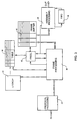
Fig. 1 is a schematic representation of a data transmission from a sending
unit 10 to a receiving unit 12, both units being generally data transmission
equipment (DTE). The transmission path between sending unit 10 and receiving
unit 12 includes a backbone 14 such as the Internet network having links
authorizing a high speed transmission whereas the network outside backbone 14
includes links authorizing only low speed transmission. Thus, the link 16 between
sending unit 10 and ingress node 18 of the backbone and the link 20 between
egress node 22 of the backbone and receiving unit 12 are generally low speed
lines. Note that sending unit 10 could be connected to backbone 14 by another
Network 24 represented by dashed lines such as a Local Area Network (LAN) or a
Wide Area Network (WAN) supporting a lower MTU than the backbone. Likewise,
egress node 22 could be connected to receiving unit 12 by another LAN or WAN
26 such as Ethernet also represented by dashed lines.
-
As illustrated in Fig. 1, the flow of data between sending unit 10 and ingress node
18 is segmented into frames 28 corresponding to short Maximum Transmission
Units (MTU). Then, data frames 28 are assembled by ingress node 18 into an
assembled data frame 30 corresponding to a long MTU compatible with the high
speed transmission within backbone 14. Data frame 30 is then de-assembled by
egress node 22 into short data frames before being transmitted to receiving unit
12.
-
It is assumed that the three consecutive data frames for the same flow of data
illustrated in Fig. 2A are received by ingress node 18. Each frame is composed of
a header field and a data field. The header fields of the three frames are of the
same type, such as of the IP/TCP type including an IP header followed by a TCP
header.
-
As illustrated in Fig. 2B, the mechanism implementing the method of the invention
in ingress node 18, assembles the three frames into a single frame. This frame
includes a main protocol header and three assembled parts containing the data
fields of the frames illustrated in Fig. 2A, each data field being preceded by an
assembly header.
The main protocol header of the assembled data frame illustrated in Fig. 2B looks
like the header of each frame illustrated in Fig. 2A. It may include one or several
levels of protocols depending on the flow characteristics. For example, an
IP/TCP/FTP flow may use a common IP/TCP header and put the FTP field in data.
For some flows, the main protocol header may be reduced to a single protocol
layer such as IP or SNA. The main protocol header of the assembled data frame
corresponds to the header of the first frame with the following changes :
- the frame length (if any) should be changed to the value that takes all the
frames appended in the assembled frame into account,
- similarly, the checksum or CRC (if any) should be changed to the value that
takes all the frames appended in the assembled frame into account,
- if required, a data pointer defining the beginning of data should be set to the
first assembly header,
- the sequence numbers NS/NR for transmit and receive and ACK number (if
any) should either be included in each assembly header or, if continuous and
ordered, only the first pair of values (or the last) may be set insofar as the
correct values can be re-built by the egress node,
- if a window field exists and is identical for all the frames, it can be let
unchanged. Otherwise, the window field should be included in each assembly
header,
- similarly, the value of any field of the headers in the consecutive frames which
is different from the corresponding field of the header in the first frame, is to be
put in the corresponding assembly header.
-
The fields contained in each assembly header of the assembled data frame are as
follows :
- a length field : for example 12 bits,
- a control field of 4 bits :
- one bit to indicate the last data field
- one bit to indicate an additional checksum field (may be used to speed up the
transmission when de-assembling allowing to avoid waiting for the global
CRC checking).
- one bit to indicate that a differential header is provided. This bit is useful
when the sequence number field, the window field or any other field is
different or unordered,
- one bit reserved
- an optional checksum field (16 or 32 bits),
- an optional differential header field that may use either a differential template by
protocol or a general purpose differential header including the following
sub-fields :
- one position sub-field giving the position of the first byte different from the
protocol header of the assembled frame,
- one length sub-field giving the number of consecutive bytes different from the
corresponding bytes of the main protocol header of the assembled frame,
- all the consecutive different bytes identified by the previous sub-fields,
- a last sub-field indicating that the data are beginning at the next position.
-
-
The mechanism used by the ingress node to implement the method of the
invention is represented in Fig. 3. Data frames corresponding to a short MTU
required by at least a low speed link are received in Protocol Processing unit 34
wherein they are identified (for example TCP/IP) and process. For protocols that
are identified, the frames are sent to Frame Processing unit 36 which controls the
storage of various information elements in a Table 38 and a Frame buffer 40
useful to build the assembled data frame illustrated in Fig. 2A and also controls a
list of pointers FREEL 42 storing the free locations of Frame Buffer 40 to be used
in the assembling method. Note that Frame Processing unit 36 could be either a
finite state machine or a program.
-
In order to identify each flow of data, Frame Processing Unit 36 requests for each
frame an address lookup of Table 38 by a Lookup unit 44. So, the frame buffer
address and other necessary information as described hereafter are extracted
from Table 38 and supplied to Frame Processing Unit 36 before a frame can be
appended to the preceding consecutive frames pertaining to the same flow in the
assembled data frame.
-
It must be noted that the lookup function can be implemented using a hashing
mechanism having a unique value depending on the address field of the frame.
This value allows to address a data field within Lookup unit 44 which contains the
address of Table 38 where the corresponding flow is stored. When there is not yet
an existing flow in Table 38, the hashing uses an address whose the data field
contains the pointer to the new flow address field of Table 38. Other classical
lookup mechanisms such as byte or bit comparison could be used. In fact, the
complexity of the Lookup unit depends upon the number of lookups to perform and
the number of bytes to compare.
-
An Assembly Processing unit 46 builds the assembled data frame by using the
information contained in Frame Buffer 40. For this, all the data frames of a flow are
read consecutively. At each address in Frame Buffer 40, the next field indicates
where the next element is or if it is the last element. For each frame to be
appended, Assembly Processing unit 46 builds the assembly header and stores it
followed by the data of the frame in First In - First Out buffer 48 until all frames are
processed. Then, the main Protocol Header is built and transmitted over the
backbone, the contents of FIFO 48 being transmitted just after it.
-
As illustrated in Fig. 4, each address location in Table 38 contains the following
fields :
- Total Size is a variable value representing the total number of bytes each time a
frame is appended in the assembled data frame. This total size is limited by the
backbone MTU which depends upon the buffer size of the backbone nodes.
Thus, this buffer size can be determined by the bit error rate. Generally, this
backbone MTU has a length comprised between 2k bytes and 8k bytes.
- Timer is a time counter which is decremented from a predetermined value to
zero. Such a predetermined value is required insofar as the time between two
frames of a same flow is unknown and unpredictable. It would be possible that
the time between the frames to be assembled be too important for the type of
data in the flow. With such a timer, the time between the first frame and the last
frame to be assembled may never overcome the predetermined time set in Table
38 at the beginning of the assembling process.
- Origin is the address of the first frame to be assembled which has been stored
in Frame Buffer 40. This value is set when receiving the first frame and remains
unchanged to be communicated to Assembly Processing unit 46 in order to know
the location of the first frame in Frame Buffer 40.
- Buffer Address is the address of the next location in Frame Buffer 40 to store
the contents of a new frame of a flow to be appended in the assembled frame.
Therefore, this value is replaced with a new one by FREEL 42 each time a frame
is identified.
-
As illustrated in Fig. 5, each address location in Frame Buffer 40 contains the
following fields :
- Next Buffer is the address of the location wherein the next frame of the flow is
to be stored. For each frame, the value of this field corresponds to the current
value of Buffer Address in Table 38.
- Data Size is the size of the data field in the frame.
- Header is the location wherein the header of the frame is stored. Note that the
size of the header is not required as the header is aligned on the right of the
header field and all empty left fields are set to 0.
- Data is the location wherein the data of the frame is stored.
-
The process used for the identification of a new frame by the ingress node is
illustrated in Fig. 6. When a new frame is received (step 50) by the ingress node,
its protocol is identified (step 52). Such an identification allows to know whether
the frame belongs to a flow type which can be assembled. If there is no
identification, the frame will not be assembled (step 54) and the process is ended.
When there is identification, required protocol processing is made (step 56). Then
a test is made (step 58) to check whether the size of the frame is greater than a
predetermined limit corresponding to the MTU used in the backbone. If so, it is not
worth assembling the frame and the process is ended to 〈〈 no assembly 〉〉 (step
54). If the frame size is less than this predetermined limit, the lookup function is
performed (step 60). This function determines whether there is already an entry in
Table 38 (step 62). Then the frame processing will be different according to
whether it is a new flow (Step 64) or the flow is already known (step 66).
-
If the lookup function has determined that the frame belongs to a new flow, the
processing is according to the flow chart illustrated in Fig. 7
-
In reference to Fig.7, when Lookup unit 44 does not find an existing flow, a new
flow has to be assigned in Table 38 (step 68) so that the lookup function points to
this flow each time a frame belonging to that flow is handled. Then, a buffer
address in Frame Buffer 40 is determined by FREEL 42 so that the frame data can
be stored in the buffer location corresponding to this address (step 70). The size of
the data is put at the same buffer address in the data size field. Then, the header
of the new frame corresponding to a master header is also stored in the buffer
(step 72). As this frame is the first frame of a flow, the buffer address is stored in
the origin field of Table 38 (step 74). For the next frame of the same flow, a new
frame buffer address given by FREEL 42 is stored at the same time in the 〈〈 buffer
address 〉〉 field of Table 38 (step 76) and in the 〈〈 next buffer 〉〉 field of the current
frame buffer address (step 78). Such an operation is necessary to chain all the
frames during the frame assembling.
-
Two additional steps are performed. First, the 〈〈 timer 〉〉 field of Table 38 is set
(step 80) according to the information provided by Protocol Processing unit 34 as
explained previously. Secondly, the 〈〈 total size 〉〉 field of Table 38 containing the
length of the assembled frame during the assembling process is set to the length
of the first frame (step 82).
-
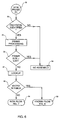
Referring to step 66 of Fig. 6, the processing steps used when the frame received
by the ingress node belongs to a known flow are represented by the flow chart of
Fig. 8. First, the size of the frame is added to the value contained in the 〈〈 total
size 〉〉 field of Table 38 (step 84) and a test is made (step 86) to check whether this
total size is greater than a predetermined limit which is generally the MTU enabled
by the backbone. Note that, inasmuch as the assembly headers included in the
assembled frame are shorter than the protocol headers of the segmented frames,
the size of the assembled frame is less than the total size of the assembled frame.
Such an approximation enables to transmit over the backbone assembled frames
the length of which is less than the authorized MTU. However, it would be possible
to compute a 〈〈 total size 〉〉 corresponding to the exact length of the assembled
data frame taking the exact size of the assembly headers into account.
-
If the 〈〈 total size 〉〉 value is greater than the predetermined limit, meaning that the
preceding total size is equal to or just below the limit, the current flow is deleted in
Table 38 while the pointer value of Lookup unit 44 is also deleted (step 88). Then,
the process goes to the assembly of the segmented frames by Assembly
Processing unit 46 as described later (step 90).
-
If the total size value is less than the predetermined limit, the frame is stored at the
buffer address given by the 〈〈 buffer address 〉〉 field of Table 38 (step 92) while the
data size is stored in the data size field at this address. Then, a differential header
with respect to the protocol header of the first frame is built and stored in the
header field of the frame buffer (step 94). It must be noted that it is not necessary
to store the length of this differential header since this one always includes a first
byte different from 0.
-
At this point, the process of Fig. 8 is identical to the process of Fig.7 when there is
no existing flow. For the next frame of the same flow, a new frame buffer address
given by FREEL 42 is stored at the same time in the 〈〈 buffer address 〉〉 field of
Table 38 (step 96) and in the 〈〈 next buffer 〉〉 field of the current frame buffer
address (step 98).
-
Finally, the last step of the process is to update the 〈〈 timer 〉〉 field of Table 38 (step
100) if necessary. This operation is required when the current frame timer is below
the value of the 〈〈 timer 〉〉 field. Such an event does not occur very often insofar as
all the frames of a flow have generally the same latency/jitter and priority settings.
-
It must be noted that the value of the 〈〈 timer 〉〉 fields of Table 38 are regularly
decremented, according to the process represented in Fig.9. The process starts
when a master timer of the ingress node (either integrated in Frame Processing
unit 36 or external) expires (step 102). Assuming that n flows are processed and
identified in Table 38, a variable n is set to 1 (step 104). Note that there are
several ways to have the list of existing flows, but the best way consists in
scanning line by line the contents of Table 38. Only addresses with non-zero fields
of 〈〈 total size 〉〉, 〈〈 timer 〉〉 and 〈〈 origin 〉〉 are taken into account. Checking only
either 〈〈 total size 〉〉 field or 〈〈 origin 〉〉 field is in fact necessary.
-
The timer value is decremented (step 106) on a regular basis, for example every
m milliseconds with m being from 1 to 9. Then, a test is made (step 108) to check
whether n has reached a value N+1 with N being the maximum number of flows in
Table 38. If so, the process returns waiting for master timer expiration. If n ≤ N a
test is made (step 110) to check whether the timer value is equal to 0. If so, this
means that frame assembling may be started for flow n (step 112) as described
hereafter. Then, the flow n is deleted in Table 38 (step 114). If the timer value is
not yet equal to 0, variable n is incremented to n+1 (step 116) and the process
loops to step 106 to perform processing of timer n+1.
-
The frame assembling made by Assembly Processing unit 46 is now described in
reference to Fig. 10. First, variables CRCF representing final checksum computed
on the assembled frame and LEN representing the length of the assembled frame
are initiated (step 118). Then, Assembly Processing unit 46 gets the value of the
〈〈 origin 〉〉 field in Table 38 (step 120). Assembly processing unit is able to perform
the assembling using only the information from Frame Buffer 40 starting with the
first frame addressed by the value of the 〈〈 origin 〉〉 field (122).
-
For each assembled part of the assembled frame corresponding to each frame,
the first step consists in building the assembly header (step 124) which is generally
simpler for the first frame since there is no differential Header. Once the assembly
header has been built, the assembled part including the assembly header and the
data is stored FIFO 48 (step 126). Then, variables CRCF and LEN are updated
according to the data stored in FIFO 48 (step 128), and the contents of Frame
Buffer 40 and Table 38 corresponding to the processed frame are cleared (step
130).
-
Then, a test is made to check whether there is a 〈〈 next buffer 〉〉 field different from
zero (step 132). If it is the case, the next frame read from the frame buffer (step
134) and the loop comes back to the beginning of the assembling process (step
124).
-
When 〈〈 next buffer 〉〉 field in the frame buffer does not contain any address, this
means that the frame which has just been processed is the last one. In such a
case, the main protocol header of the assembled frame is built using the values of
variables CRCF and LEN updated at each frame being processed (step 136).
Then, the main protocol header is transmitted (step 138) followed by the contents
of FIFO 48 (step 140) which contains all the assembled parts of the assembled
frame.
-
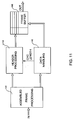
When the assembled data frame is received by the egress node, it is
de-assembled using a device represented in Fig. 11. First, the assembled data
frame is received by Protocol Processing unit 142 wherein the protocol header is
identified in order to recognize an assembled data frame and a split is performed
between header and data fields. The main protocol header and the assembly
headers are sent to Header Processing unit 144 whereas the data fields are sent
to Data Handling unit 146. Each protocol header specific to a frame which has
been re-built from the main protocol header of the assembled frame and the
assembly header are stored in Frame Buffer 148 at an address defined by a
pointer whereas the corresponding data are transferred from Data Handling unit
146 to frame buffer 148 in the same location as the protocol header. Note that the
protocol header of each frame is re-built by Header Processing 144 by using the
CRC and Length of the data field on line 150 from Data Handling unit 146.
-
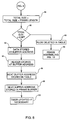
In reference to Fig. 12, the process used in the egress node for de-assembling the
assembled data frames is now described. When a new frame is received, the
protocol is first identified (step 152) in order to determine whether the frame is an
assembled data frame or not (step 154). If it is not an assembled frame, there is
no de-assembling (step 156) and the frame is transmitted as such. If it is an
assembled frame, a variable n is set to 1 (step 158), the protocol header of the
assembled frame is transmitted to Header Processing unit 144 (step 160) and the
first assembly header is also transmitted to Header Processing unit 144 (step 162)
whereas the corresponding data are transmitted to Data Handling unit 146 (step
164).
-
Then, the protocol header of the frame is re-built (step 166) by Header Processing
unit 144 using the CRC and the data length provided by Data Handling unit 146
and the differential header of the assembled part. After this, a test is made to
check whether the assembled pad which has been processed is the last one of the
assembled frame (step 168). If not, variable n is incremented to n+1 (step 170)
and the process loops to the processing of the next assembled pad of the
assembled frame (step 162).
-
If there is no more assembled part to be processed, a final CRC checking is
performed to validate the segmented frames before resending them. For this, the
CRC of the assembled data frame is computed (step 172). The computed CRC is
compared to the CRC value received in the assembled frame header (step 174). If
the comparison is positive, there is no problem and the segmented frames are
transmitted with their valid CRC (step 176). But, if the computed CRC is different
from the received CRC, the frames are sent with a bad CRC (step 178). As a
matter of fact, without adding a specific CRC or checksum field in each assembly
header (as proposed optionally) corresponding to the CRC or checksum of the
assembled frame, there is no method to know which frame is corrupted when a
failure occurred in the assembled frame received by the egress node, either
because one or several bits have been inverted, or because the CRC or checksum
value of the frame has been changed. It must be noted that it is better to send the
corrupted frame in order to ask for a retry to the sender than to abort the frame
transmission as the communication timer may take more time to expire than the
time to receive and process the corrupted frame.