EP1656304B1 - Fluid product dispensing head - Google Patents
Fluid product dispensing head Download PDFInfo
- Publication number
- EP1656304B1 EP1656304B1 EP04767674A EP04767674A EP1656304B1 EP 1656304 B1 EP1656304 B1 EP 1656304B1 EP 04767674 A EP04767674 A EP 04767674A EP 04767674 A EP04767674 A EP 04767674A EP 1656304 B1 EP1656304 B1 EP 1656304B1
- Authority
- EP
- European Patent Office
- Prior art keywords
- base
- dispenser
- orifice
- axial
- head according
- Prior art date
- Legal status (The legal status is an assumption and is not a legal conclusion. Google has not performed a legal analysis and makes no representation as to the accuracy of the status listed.)
- Expired - Lifetime
Links
- 239000012530 fluid Substances 0.000 title claims description 20
- 238000006073 displacement reaction Methods 0.000 claims description 7
- 230000000694 effects Effects 0.000 description 5
- 239000000470 constituent Substances 0.000 description 4
- 238000007790 scraping Methods 0.000 description 4
- 238000007789 sealing Methods 0.000 description 4
- 239000007788 liquid Substances 0.000 description 2
- 150000003839 salts Chemical class 0.000 description 2
- 235000002566 Capsicum Nutrition 0.000 description 1
- 239000006002 Pepper Substances 0.000 description 1
- 235000016761 Piper aduncum Nutrition 0.000 description 1
- 235000017804 Piper guineense Nutrition 0.000 description 1
- 244000203593 Piper nigrum Species 0.000 description 1
- 235000008184 Piper nigrum Nutrition 0.000 description 1
- 239000002537 cosmetic Substances 0.000 description 1
- 239000006071 cream Substances 0.000 description 1
- 230000000994 depressogenic effect Effects 0.000 description 1
- 235000013305 food Nutrition 0.000 description 1
- 238000000465 moulding Methods 0.000 description 1
- 238000004806 packaging method and process Methods 0.000 description 1
- 239000000843 powder Substances 0.000 description 1
- 239000002453 shampoo Substances 0.000 description 1
- 230000003068 static effect Effects 0.000 description 1
Images


Classifications
-
- B—PERFORMING OPERATIONS; TRANSPORTING
- B65—CONVEYING; PACKING; STORING; HANDLING THIN OR FILAMENTARY MATERIAL
- B65D—CONTAINERS FOR STORAGE OR TRANSPORT OF ARTICLES OR MATERIALS, e.g. BAGS, BARRELS, BOTTLES, BOXES, CANS, CARTONS, CRATES, DRUMS, JARS, TANKS, HOPPERS, FORWARDING CONTAINERS; ACCESSORIES, CLOSURES, OR FITTINGS THEREFOR; PACKAGING ELEMENTS; PACKAGES
- B65D47/00—Closures with filling and discharging, or with discharging, devices
- B65D47/04—Closures with discharging devices other than pumps
- B65D47/20—Closures with discharging devices other than pumps comprising hand-operated members for controlling discharge
- B65D47/24—Closures with discharging devices other than pumps comprising hand-operated members for controlling discharge with poppet valves or lift valves, i.e. valves opening or closing a passageway by a relative motion substantially perpendicular to the plane of the seat
- B65D47/241—Closures with discharging devices other than pumps comprising hand-operated members for controlling discharge with poppet valves or lift valves, i.e. valves opening or closing a passageway by a relative motion substantially perpendicular to the plane of the seat the valve being opened or closed by actuating a cap-like element
- B65D47/242—Closures with discharging devices other than pumps comprising hand-operated members for controlling discharge with poppet valves or lift valves, i.e. valves opening or closing a passageway by a relative motion substantially perpendicular to the plane of the seat the valve being opened or closed by actuating a cap-like element moving helically
Definitions
- the present invention relates to a fluid dispenser head intended to be associated with a fluid reservoir.
- This dispensing head generally comprises a fixed base formed by or mounted on the tank.
- the head includes a rotary actuator rotatably mounted on the base about an axis between two end stop positions.
- the head comprises a dispensing orifice selectively closable by rotation of the actuating element on the base.
- This type of dispensing head is frequently used as an actuatable closure system for the dispensing of liquid, granular or powder fluid product stored in a reservoir.
- a preferred application of this kind of head exists in the fields of the food industry, body care or cosmetics. Other fields are not excluded, however.
- a dispensing head according to the preamble of claim 1 is known from US-A-5000360.
- this type of manifold distribution head and rotary actuating element is operable between an open position and a closed position by rotating the actuating element on the base. It is also known that the rotation of the rotary element on the base makes it possible to unmask or disengage one or more orifice (s) of closed distribution (s) in the closed position. Heads provided with several dispensing orifices of different cross sections are also known so that the flow rate of the fluid product can be varied through the dispensing orifices.
- the present invention relates to a type of dispensing head with a single dispensing orifice. The orifice may, however, comprise several holes. With this type of dispensing head with a single dispensing orifice, the rotary displacement of the actuating element only makes it possible to close or disengage the dispensing orifice between the two extreme stop positions.
- the present invention aims to define a dispensing head with a single dispensing orifice which allows modular use of the dispensing orifice. Another object of the invention is to allow a graduated clearance of the dispensing orifice.
- the present invention proposes a dispensing head according to claim 1.
- the two extreme stop positions during the rotation of the actuating element on the base, define two opening positions of the dispensing orifice separated by at least one intermediate position of closure of the dispensing orifice.
- the dispensing head comprises flow variation means making it possible to vary the flow rate of the fluid product through the dispensing orifice from one open position to the other. Therefore, an open position allows more fluid to be dispensed than the other open position for a given time. This gives a modular distribution of fluid product through a single dispensing orifice.
- the dispensing orifice is located on the axis of rotation of the element on the base.
- the packaging or dispenser equipped with the dispensing head according to the invention is then in the form of a salt shaker or a conventional pepper with a single axial central distribution orifice.
- the dispensing head comprises axial displacement means able to move the element axially relative to the base during its rotation on the base.
- the axial displacement means comprise at least one guide path having two different sections connected together at a low point, the two sections each defining a respective end stop, the two end stops respectively corresponding to the two open positions and the low point corresponding to the closed position.
- the base forms at least one guide window axial rotator which extends over a periphery portion of the base, said window defining a guide path, said window forming two window sections connected together, a first section defining a first slope and the second section defining a second different slope of the first slope, each section defining a stop end, the abutment ends being axially offset, the actuating element comprising at least one axial rotational guide pin engaged in said window so that a rotation of the element actuation on the base has the effect of moving said at least one lug in its respective window, thus moving the actuating element axially to reach different heights depending on whether the lug is in abutment on the first or the second section.
- the base comprises a ring formed with several axial rotary guide windows distributed over the periphery of the ring, the cap comprising a skirt which extends around the ring and which internally forms a plurality of guide pins. axial rotary engaged in respective windows.
- the element forms the dispensing orifice and the base forms a shutter needle engaged in the closed position in the dispensing orifice, and disengaged from the orifice in the positions of opening differently so that the flow rates through the orifice are different in the two open positions. It is the more or less pronounced disengagement of the valve from the dispensing opening which makes it possible to vary the flow from one opening position to the other. More precisely, this more or less pronounced disengagement makes it possible to vary the passage section of the fluid product just downstream of the single dispensing orifice.
- the actuating element comprises axial guiding means engaged around the needle so that the needle is slidably mounted in said axial guiding means, said guiding means extending downwards from the periphery of the lug. distribution orifice, said guide means forming a plurality of lights of variable sizes in depending on the position of the needle in the axial guide means.
- the axial guide means comprise a plurality of tabs which extend downwards from the outer periphery of the dispensing orifice, said tabs being connected by a scraping ring slidably engaged around the needle. .
- the base may comprise an internal sleeve inside which the needle extends, the actuating element comprising a cover disposed on the sleeve and forming the dispensing orifice, said cap comprising an annular lip in sliding contact. rotary seal in said sleeve.
- the actuating element comprises a detachable guarantee tongue blocked by the base so that the actuating element is locked in rotation on the base in the closed position.
- the fluid dispenser equipped with the dispensing head according to the invention comprises a reservoir 1 for containing fluid, for example salt, a cream or a shampoo. More generally, the fluid product may be liquid, granular or powdery.
- the tank 1 forms at its upper end a snap groove 11, a shoulder 12 which extends radially inwards and which terminates in a neck 13.
- the neck 13 defines an opening allowing the fluid product stored in the reservoir to be extracted.
- the reservoir is not a critical component for the present invention: it can be of any shape and size. Even the snap groove 11 and the shoulder 12 and the neck 13 may have a different configuration without departing from the scope of the present invention.
- This reservoir 1 is here associated with a dispensing head comprising two constituent elements, namely a base 2 and a rotary actuating element 3.
- the base 2 is here mounted on the reservoir 1, but it is also possible to envisage that the base 2 is made integrally with the reservoir 1.
- the dispensing head here comprises only two constituent elements, it is not excluded that it may further comprise other constituent elements in certain embodiments that do not come out. not the scope of the invention. An example with two constituent elements is, however, advantageous from the point of view of molding and assembly.
- the base 2 comprises an inner sleeve 21 defining a lower end portion 211 in sealing contact in the neck 13. This is a static sealing contact, since the base 2 is intended to be fixedly mounted on the reservoir 1.
- the sleeve 21 defines an internal passage which is in direct communication with the interior of the reservoir 1, since the sleeve is disposed inside the neck 13.
- a needle 20 defining an outer upper end 201 is centrally and axially disposed inside the sleeve 21.
- Holding flanges 202 connect the inner wall of the sleeve 21 to the needle 20.
- needle 20 preferably has a cylindrical outer wall from its upper end 201.
- the sleeve 21 is connected at its upper end to a ring 22 which extends coaxially around the sleeve 21.
- the ring 22 is provided with a plurality of windows 221 which provide openings in the wall of the ring 22. These windows 221, which here are three in number, form a guide path. The windows are equiangularly distributed around the periphery of the crown 22.
- Each window 221 is substantially in the form of a chevron with the point directed downwards.
- each window 221 defines a first window section 2211 and a second window section 2212. Each section is in the form of a substantially rectilinear slit or ramp, but inclined with respect to the horizontal or the vertical.
- each section has a slope 2215, 2216 having a certain length, a certain profile and a certain degree of inclination.
- the degrees of inclination of the two slopes may be identical, but preferably, according to the invention the degrees of inclination of these two slopes are different.
- the first section 2211 has a slope inclination degree lower than the second window section 2212.
- each window section 2211 and 2212 are connected together at a low point 2210.
- each window section includes a stop end 2213, 2214 which defines the extreme extent of the window sections. These abutment ends 2213 and 2214 are here equidistant from the low point 2210, so that each section of windows has an identical length.
- the abutment ends 2213 and 2214 are not located in the same plane, but instead axially offset. Since the slope inclination degree of the second section 2212 is greater than that of the first section 2211, the abutment end 2214 is located axially higher than the abutment end 2213. This axial offset of the ends the stop of the two sections of windows can also be obtained with identical inclination degrees of slopes, but with lengths of slopes of sections different windows.
- the abutment end 2214 would also be axially offset upwards with respect to the abutment end 2213
- the axial offset of the stop ends of the windows 221 can be achieved by varying either the slope degree of the window section slopes or the slope lengths of the window sections. It is also possible to envisage a combination of different lengths and degrees of inclination. However, it is not excluded according to the invention that the stop ends of the windows are arranged in the same plane. However, the offset of these ends is preferred.
- slopes 2215 and 2216 each form a recess 2217 and 2218 which breaks the linearity of the slope.
- These recesses, notches or bearings define intermediate positions between the low point 2210 and the abutment ends 2213 and 2214.
- the base 1 forms around the ring 22 a complex configuration that is not regular around the perimeter of the crown.
- the base forms two buttresses 24 interrupted on the one hand by a lower slot 25 and on the other by a range 26.
- the slot 25 is located below the buttresses 24 and the beach 26 is also located. 25 against the buttresses 25, at a height even lower than that of the slot 25.
- the slot 25 is located substantially diametrically opposite the range 26.
- the slot 25 extends over an angle of about 10 to 30 °, while the range 26 extends over an angular distance of more than 90 °.
- the base also forms at its lower outer periphery a snap-fastening collar 23 intended to cooperate with the detent groove 11 formed by the reservoir 1.
- the base 2 is fixedly mounted on the reservoir 1 at the of the groove 11, and this sealingly through the sealed engagement of the lower end portion 211 of the sleeve 21 in the neck 13.
- the rotary actuating element 3 is here in the form of a cover comprising a rotary shutter plate 31 pierced centrally with a dispensing orifice 30.
- the needle 20 is engaged substantially sealingly in the dispensing orifice 30 in FIGS. 1, 2 and 3.
- the plate 31 forms on the lower periphery of the dispensing orifice 30 an axial guide tumbler 36 which extends around the needle 20 over a certain height.
- This turret 36 is constituted by a plurality of tabs connecting the periphery of the dispensing orifice 30 to a scraper ring 362.
- the turret thus defines a plurality of passage apertures 363 between each tab 361. This is visible in FIG.
- these lights 363 form a communication passage between the internal space formed by the sleeve 21 in communication direct with the tank and the outside of the head.
- the fluid product stored in the tank 1 can flow through the dispensing orifice 30 through the passage lumens 363, when the needle 20 is withdrawn inside the head.
- the guiding and scraping turret 36 not only keeps the needle 20 in the axis of rotation of the head, but also makes it possible to clean the needle 20 with each rotation of the actuating element by a scraping effect obtained. by moving the needle in the turret.
- the ring 362 and the tabs 361 participate in this scraping action.
- the plate 31 is extended at its outer periphery by a skirt 32 which extends downwards.
- This skirt 32 is arranged concentrically around the ring 22.
- the skirt 32 here forms three lugs 221 which are engaged in respective windows 221 formed by the ring 22. This is visible in Figure 1, for a lug and a window .
- the skirt 32 comprises three lugs 321 distributed equiangularly at 120 ° on the periphery of the inner wall of the skirt 32. Since each lug 321 is engaged in a respective window 221, and this window presents a profile with two identical or different slopes, a rotation of the rotary actuating element 3 on the base 2 has the effect of moving the lugs in the windows following the profile of the slopes.
- the rotary actuating element 3 When the pins 321 are located at the 2210 of the windows 221, the rotary actuating element 3 is at its lowest level relative to the base 2. The needle 20 is then located at its highest level in the guide and scraper turret. 36. This corresponds to the closed position of the dispensing head shown in Figures 1, 2 and 3, wherein the upper end 201 of the needle 20 is located in the dispensing orifice 30 advantageously sealed. It can also be noted that the upper end 201 is located substantially in the same plane as the plate 31.
- Another opening position can of course be reached when the lugs abut against the other end stops of the windows.
- the abutment ends 2213 and 2214 are located in the same horizontal plane, that is to say when there is no axial offset between these abutment ends, the needle is depressed or disengaged in the same way with the same magnitude in the two open positions.
- the ends of abutment 2213 and 2214 are axially offset as in the preferred embodiment of the invention, the two open positions correspond to two different engagement or depression positions of the needle 20 relative to the dispensing orifice 30.
- the recesses 2217 and 2218 formed by the slopes 2215 and 2216 define stable opening intermediate positions corresponding to a fixed intermediate flow rate.
- two extreme open positions separated by a plurality of fixed intermediate opening positions and at least one fixed intermediate closing position it is possible to define two extreme open positions separated by a plurality of fixed intermediate opening positions and at least one fixed intermediate closing position. Indeed, one can provide several closing positions and more than two intermediate opening positions, or on the contrary only one intermediate opening position on one of the two slopes.
- the more or less marked or pronounced depression of the needle 20 in the turret 36, respectively in the dispensing orifice 30, makes it possible to vary the flow rate of fluid.
- the engagement of the lugs in the windows is axial displacement means while ensuring a rotation guide.
- the rotary actuating element 3 forms a sealing lip 33 in rotary sealing contact in the sleeve 21. This ensures a perfect dynamic seal of the dispensing head.
- the actuating element 3 also forms an actuating button 34 which aids in the rotational manipulation of the element 3. This actuating button 34 is situated at the level of the range 26 between the two buttresses 24. When the button 34 is in abutment against the rear buttress, when looking at Figure 4, the dispensing head is in a low flow opening position. On the other hand, when the actuating button 34 is in abutment against the other buttress 24 normally located in the foreground in FIG. 5, the dispensing head is in the open position at a high speed.
- the rotary actuating element also comprises first-use guarantee means in the form of a tongue 35 made integrally with the remainder of the actuating element 3 and disposed at the level of the
- the tongue 35 preferably extends over the entire width of the crenel 25 so as to abut with the two adjacent buttresses 24. In this way, the rotary actuating element 3 is locked in rotation in the closed position. This is clearly visible in FIG. 2, as well as in FIG. 3. To actuate the dispensing head, the tongue 35 must first be torn off.
- the displacement means in the form of the cooperation between lugs and chevron-shaped windows can be likened to a kind of chevron-shaped threading with identical or different inclination slopes and with identical slope lengths. or different.
Landscapes
- Engineering & Computer Science (AREA)
- Mechanical Engineering (AREA)
- Closures For Containers (AREA)
- Containers And Packaging Bodies Having A Special Means To Remove Contents (AREA)
- Devices For Dispensing Beverages (AREA)
- Coating Apparatus (AREA)
- Feeding, Discharge, Calcimining, Fusing, And Gas-Generation Devices (AREA)
Description
La présente invention concerne une tête de distribution de produit fluide destinée à être associée à un réservoir de produit fluide. Cette tête de distribution comprend généralement une embase fixe formée par ou montée sur le réservoir. En outre, la tête comprend un élément d'actionnement rotatif monté de manière rotative sur l'embase autour d'un axe entre deux positions de butée extrêmes. D'autre part, la tête comprend un orifice de distribution sélectivement obturable par rotation de l'élément d'actionnement sur l'embase. Ce genre de tête de distribution est fréquemment utilisé en tant que système de fermeture actionnable pour la distribution de produit fluide liquide, granulaire ou pulvérulent stocké dans un réservoir. Une application privilégiée de ce genre de tête existe dans les domaines de l'industrie alimentaire, de soin corporel ou encore de la cosmétique. D'autres domaines ne sont cependant pas exclus. Une tête de distribution selon le préambule de la revendication 1 est connue de US-A-5000360.The present invention relates to a fluid dispenser head intended to be associated with a fluid reservoir. This dispensing head generally comprises a fixed base formed by or mounted on the tank. In addition, the head includes a rotary actuator rotatably mounted on the base about an axis between two end stop positions. On the other hand, the head comprises a dispensing orifice selectively closable by rotation of the actuating element on the base. This type of dispensing head is frequently used as an actuatable closure system for the dispensing of liquid, granular or powder fluid product stored in a reservoir. A preferred application of this kind of head exists in the fields of the food industry, body care or cosmetics. Other fields are not excluded, however. A dispensing head according to the preamble of
En général, ce type de tête de distribution à embase et élément d'actionnement rotatif est actionnable entre une position d'ouverture et une position de fermeture en faisant tourner l'élément d'actionnement sur l'embase. Il est également connu que la rotation de l'élément rotatif sur l'embase permet de démasquer ou de dégager un ou plusieurs orifice(s) de distribution obturé(s) en position de fermeture. On connaît également des têtes pourvues de plusieurs orifices de distribution de sections différentes de manière pouvoir faire varier le débit d'écoulement du produit fluide à travers les orifices de distribution. Toutefois, la présente invention concerne un type de tête de distribution à orifice de distribution unique. L'orifice peut toutefois comprendre plusieurs trous. Avec ce type de tête de distribution à orifice de distribution unique, le déplacement rotatif de l'élément d'actionnement permet uniquement d'obturer ou dégager l'orifice de distribution entre les deux positions extrêmes de butée.In general, this type of manifold distribution head and rotary actuating element is operable between an open position and a closed position by rotating the actuating element on the base. It is also known that the rotation of the rotary element on the base makes it possible to unmask or disengage one or more orifice (s) of closed distribution (s) in the closed position. Heads provided with several dispensing orifices of different cross sections are also known so that the flow rate of the fluid product can be varied through the dispensing orifices. However, the present invention relates to a type of dispensing head with a single dispensing orifice. The orifice may, however, comprise several holes. With this type of dispensing head with a single dispensing orifice, the rotary displacement of the actuating element only makes it possible to close or disengage the dispensing orifice between the two extreme stop positions.
La présente invention a pour but de définir une tête de distribution à orifice de distribution unique qui permet une utilisation modulaire de l'orifice de distribution. Un autre but de l'invention est de permettre un dégagement gradué de l'orifice de distribution.The present invention aims to define a dispensing head with a single dispensing orifice which allows modular use of the dispensing orifice. Another object of the invention is to allow a graduated clearance of the dispensing orifice.
Pour atteindre ces buts, la présente invention propose une tête de distribution selon la revendication 1. Les deux positions de butée extrêmes, lors de la rotation de l'élément d'actionnement sur l'embase, définissent deux positions d'ouverture de l'orifice de distribution séparées par au moins une position intermédiaire de fermeture de l'orifice de distribution. Ainsi, par une simple rotation de l'élément d'actionnement sur l'embase dans le sens des aiguilles d'une montre et dans le sens inverse des aiguilles d'une montre, on atteint deux positions d'ouverture disposées avantageusement de manière symétrique par rapport à la position de fermeture. Selon l'invention, la tête de distribution comprend des moyens de variation de débit permettant de faire varier le débit d'écoulement du produit fluide à travers l'orifice de distribution d'une position d'ouverture à l'autre. Par conséquent, une position d'ouverture permet de distribuer plus de produit fluide que l'autre position d'ouverture pour un temps donné. On obtient ainsi une distribution modulaire de produit fluide à travers un orifice de distribution unique.To achieve these objects, the present invention proposes a dispensing head according to
L'orifice de distribution est situé sur l'axe de rotation de l'élément sur l'embase. Le conditionnement ou le distributeur équipé de la tête de distribution selon l'invention se présente alors sous la forme d'une salière ou d'un poivrier conventionnel avec un orifice de distribution central axial unique.The dispensing orifice is located on the axis of rotation of the element on the base. The packaging or dispenser equipped with the dispensing head according to the invention is then in the form of a salt shaker or a conventional pepper with a single axial central distribution orifice.
Selon une autre caractéristique de l'invention, la tête de distribution comprend des moyens de déplacement axial aptes à déplacer l'élément axialement par rapport à l'embase lors de sa rotation sur l'embase.According to another characteristic of the invention, the dispensing head comprises axial displacement means able to move the element axially relative to the base during its rotation on the base.
Les moyens de déplacement axial comprennent au moins un chemin de guidage présentant deux sections différentes reliées ensemble au niveau d'un point bas, les deux sections définissant chacune une butée extrême respective, les deux butées extrêmes correspondant respectivement aux deux positions d'ouverture et le point bas correspondant à la position de fermeture. De préférence, l'embase forme au moins une fenêtre de guidage rotatif axial qui s'étend sur une partie de périphérie de l'embase, ladite fenêtre définissant un chemin de guidage, ladite fenêtre formant deux sections de fenêtres reliées ensemble, une première section définissant une première pente et la seconde section définissant une seconde pente différente de la première pente, chaque section définissant une extrémité de butée, les extrémités de butée étant décalées axialement, l'élément d'actionnement comprenant au moins un ergot de guidage rotatif axial engagé dans ladite fenêtre de sorte qu'une rotation de l'élément d'actionnement sur l'embase a pour effet de déplacer ledit au moins un ergot dans sa fenêtre respective, déplaçant ainsi l'élément d'actionnement axialement pour atteindre des hauteurs différentes selon que l'ergot est en butée sur la première ou la seconde section. Et pour faire varier le débit, les pentes présentent des inclinaisons et/ou des longueurs différentes. Selon une forme de réalisation pratique, l'embase comprend une couronne formée avec plusieurs fenêtres de guidage rotatif axial réparties sur la périphérie de la couronne, le capot comprenant une jupe qui s'étend autour de la couronne et qui forme intérieurement plusieurs ergots de guidage rotatif axial engagés dans des fenêtres respectives.The axial displacement means comprise at least one guide path having two different sections connected together at a low point, the two sections each defining a respective end stop, the two end stops respectively corresponding to the two open positions and the low point corresponding to the closed position. Preferably, the base forms at least one guide window axial rotator which extends over a periphery portion of the base, said window defining a guide path, said window forming two window sections connected together, a first section defining a first slope and the second section defining a second different slope of the first slope, each section defining a stop end, the abutment ends being axially offset, the actuating element comprising at least one axial rotational guide pin engaged in said window so that a rotation of the element actuation on the base has the effect of moving said at least one lug in its respective window, thus moving the actuating element axially to reach different heights depending on whether the lug is in abutment on the first or the second section. And to vary the flow, the slopes have different inclinations and / or lengths. According to a practical embodiment, the base comprises a ring formed with several axial rotary guide windows distributed over the periphery of the ring, the cap comprising a skirt which extends around the ring and which internally forms a plurality of guide pins. axial rotary engaged in respective windows.
Selon un autre aspect de l'invention, l'élément forme l'orifice de distribution et l'embase forme un pointeau d'obturation engagé en position de fermeture dans l'orifice de distribution, et désengagé de l'orifice dans les positions d'ouverture de manière différente de sorte que les débits à travers l'orifice sont différents dans les deux positions d'ouverture. C'est le désengagement plus ou moins prononcé du pointeau de l'ouverture de distribution qui permet de faire varier le débit d'une position d'ouverture à l'autre. Plus précisément, ce désengagement plus ou moins prononcé permet de faire varier la section de passage du produit fluide juste en aval de l'orifice de distribution unique. Avantageusement, l'élément d'actionnement comprend des moyens de guidage axial engagé autour du pointeau de sorte que le pointeau est monté coulissant dans lesdits moyens de guidage axial, lesdits moyens de guidage s'étendant vers le bas à partir de la périphérie de l'orifice de distribution, lesdits moyens de guidage formant plusieurs lumières de tailles variables en fonction de la position du pointeau dans les moyens de guidage axial. Selon une forme de réalisation pratique, les moyens de guidage axial comprennent plusieurs pattes qui s'étendent vers le bas à partir de la périphérie externe de l'orifice de distribution, lesdites pattes étant reliées par un anneau de raclage engagé à coulissement autour du pointeau. L'embase peut comprendre un manchon interne à l'intérieur duquel s'étend le pointeau, l'élément d'actionnement comprenant un capot disposé sur le manchon et formant l'orifice de distribution, ledit capot comprenant une lèvre annulaire en contact de coulissement rotatif étanche dans ledit manchon. Selon une autre caractéristique de l'invention, l'élément d'actionnement comprend une languette de garantie détachable bloquée par l'embase de sorte que l'élément d'actionnement est bloqué en rotation sur l'embase en position de fermeture.According to another aspect of the invention, the element forms the dispensing orifice and the base forms a shutter needle engaged in the closed position in the dispensing orifice, and disengaged from the orifice in the positions of opening differently so that the flow rates through the orifice are different in the two open positions. It is the more or less pronounced disengagement of the valve from the dispensing opening which makes it possible to vary the flow from one opening position to the other. More precisely, this more or less pronounced disengagement makes it possible to vary the passage section of the fluid product just downstream of the single dispensing orifice. Advantageously, the actuating element comprises axial guiding means engaged around the needle so that the needle is slidably mounted in said axial guiding means, said guiding means extending downwards from the periphery of the lug. distribution orifice, said guide means forming a plurality of lights of variable sizes in depending on the position of the needle in the axial guide means. According to a practical embodiment, the axial guide means comprise a plurality of tabs which extend downwards from the outer periphery of the dispensing orifice, said tabs being connected by a scraping ring slidably engaged around the needle. . The base may comprise an internal sleeve inside which the needle extends, the actuating element comprising a cover disposed on the sleeve and forming the dispensing orifice, said cap comprising an annular lip in sliding contact. rotary seal in said sleeve. According to another characteristic of the invention, the actuating element comprises a detachable guarantee tongue blocked by the base so that the actuating element is locked in rotation on the base in the closed position.
Ainsi, en faisant tourner l'élément d'actionnement sur l'embase d'un côté et de l'autre à partir de la position de fermeture intermédiaire, on atteint deux positions d'ouverture dans lesquelles l'élévation axiale de l'élément d'actionnement est différente. Cela provient du fait qu'une butée extrême est située axialement plus haute que l'autre. Ceci se répercute directement sur la hauteur de désengagement du pointeau à l'intérieur de l'orifice de distribution, ce qui permet de faire varier le débit d'écoulement.Thus, by rotating the actuating element on the base on one side and the other from the intermediate closed position, two opening positions are reached in which the axial elevation of the element Actuation is different. This is because one extreme stop is located axially higher than the other. This has a direct effect on the needle's disengagement height inside the dispensing orifice, which makes it possible to vary the flow rate.
L'invention sera maintenant décrite plus amplement en référence aux dessins joints donnant à titre d'exemple non limitatif un mode de réalisation de l'invention.The invention will now be described more fully with reference to the accompanying drawings giving by way of non-limiting example an embodiment of the invention.
Sur les figures :
- la figure 1 est une vue en perspective partiellement découpée d'un distributeur de produit fluide équipé d'une tête de distribution selon l'invention,
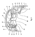
- la figure 2 est une vue agrandie de la tête de distribution de la figure 1,
- la figure 3 est une vue en perspective en coupe transversale verticale de la tête de distribution des figures précédentes en position fermée,
- la figure 4 est une vue similaire à celle de la figure 3 dans une position d'ouverture, et
- la figure 5 est une vue semblable à celle de la figure 4 dans l'autre position d'ouverture.
- FIG. 1 is a partially cutaway perspective view of a fluid dispenser equipped with a dispensing head according to the invention,
- FIG. 2 is an enlarged view of the dispensing head of FIG. 1,
- FIG. 3 is a vertical cross-sectional perspective view of the dispensing head of the preceding figures in the closed position,
- FIG. 4 is a view similar to that of FIG. 3 in an open position, and
- Figure 5 is a view similar to that of Figure 4 in the other open position.
Le distributeur de produit fluide équipé de la tête de distribution selon l'invention comprend un réservoir 1 destiné à contenir du produit fluide, par exemple du sel, une crème ou un shampooing. Plus généralement, le produit fluide peut être liquide, granulaire ou pulvérulent. Le réservoir 1 forme à son extrémité supérieure une rainure d'encliquetage 11, un épaulement 12 qui s'étend radialement vers l'intérieur et qui se termine par un col 13. Le col 13 définit une ouverture permettant au produit fluide stocké dans le réservoir d'en être extrait. Le réservoir n'est pas un composant critique pour la présente invention : il peut présenter une forme et une taille quelconque. Même la rainure d'encliquetage 11 ainsi que l'épaulement 12 et le col 13 peuvent présenter une configuration différente sans pour autant sortir du cadre de la présente invention.The fluid dispenser equipped with the dispensing head according to the invention comprises a
Ce réservoir 1 est ici associé à une tête de distribution comprenant deux éléments constitutifs, à savoir une embase 2 et un élément d'actionnement rotatif 3. L'embase 2 est ici montée sur le réservoir 1, mais on peut également envisager que l'embase 2 soit réalisée de manière monobloc avec le réservoir 1. Bien que la tête de distribution comprenne ici que deux éléments constitutifs, il n'est pas exclut qu'elle puisse comprendre encore d'autres éléments constitutifs dans certains modes de réalisation qui ne sortent pas du cadre de l'invention. Un exemple à deux éléments constitutifs est cependant avantageux, d'un point de vue du moulage et de l'assemblage.This
En se référant indifféremment aux figures, on peut voir que l'embase 2 comprend un manchon interne 21 définissant une partie d'extrémité inférieure 211 en contact étanche dans le col 13. Il s'agit là d'un contact d'étanchéité statique, étant donné que l'embase 2 est destinée à être montée fixement sur le réservoir 1. Le manchon 21 définit un passage interne qui est en communication directe avec l'intérieur du réservoir 1, étant donné que le manchon est disposé à l'intérieur du col 13. Un pointeau 20 définissant une extrémité supérieure externe 201 est disposé de manière centrale et axiale à l'intérieur du manchon 21. Des brides de maintien 202 relient la paroi interne du manchon 21 au pointeau 20. Le pointeau 20 présente de préférence une paroi externe cylindrique à partir de son extrémité supérieure 201. Le manchon 21 est relié au niveau de son extrémité supérieure à une couronne 22 qui s'étend coaxialement autour du manchon 21. Comme on peut le voir sur certaines figures, et en particulier sur la figure 2, la couronne 22 est pourvue de plusieurs fenêtres 221 qui réalisent des ouvertures dans la paroi de la couronne 22. Ces fenêtres 221, qui sont ici au nombre de trois, forment un chemin de guidage. Les fenêtres sont réparties de manière équiangulaire sur la périphérie de la couronne 22. Chaque fenêtre 221 se présente sensiblement sous la forme d'un chevron avec la pointe dirigée vers le bas. Ainsi, chaque fenêtre 221 définit une première section de fenêtre 2211 et une seconde section de fenêtre 2212. Chaque section se présente sous la forme d'une fente ou rampe sensiblement rectiligne, mais inclinée par rapport à l'horizontal ou la verticale. Ainsi, chaque section présente une pente 2215, 2216 ayant une certaine longueur, un certain profil et un certain degré d'inclinaison. Les degrés d'inclinaison des deux pentes peuvent être identiques, mais de préférence, selon l'invention les degrés d'inclinaison de ces deux pentes sont différents. En effet, la première section 2211 présente un degré d'inclinaison de pente inférieur à la seconde section de fenêtre 2212. D'autre part, chaque section de fenêtre 2211 et 2212 sont reliées ensemble au niveau d'un point bas 2210. A l'opposé, chaque section de fenêtres comprend une extrémité de butée 2213, 2214 qui définit l'étendue extrême des sections de fenêtres. Ces extrémités de butée 2213 et 2214 sont ici équidistantes du point bas 2210, de sorte que chaque section de fenêtres présente une longueur identique. Etant donné que les degrés d'inclinaison des pentes des sections de fenêtres sont différents, et que leurs longueurs sont identiques, les extrémités de butée 2213 et 2214 ne sont pas situées dans un même plan, mais au contraire décalées axialement. Etant donné que le degré d'inclinaison de pentes de la seconde section 2212 est supérieur à celui de la première section 2211, l'extrémité de butée 2214 est donc située axialement plus haut que l'extrémité de butée 2213. Ce décalage axial des extrémités de butée des deux sections de fenêtres peut également être obtenu avec des degrés d'inclinaison de pentes identiques, mais avec des longueurs de pentes de sections de fenêtres différentes. En effet, en prévoyant une section de fenêtre 2212 plus longue que la section de fenêtre 2211, mais avec des degrés d'inclinaison identiques, l'extrémité de butée 2214 serait également décalée axialement vers le haut par rapport à l'extrémité de butée 2213. Par conséquent, le décalage axial des extrémités de butée des fenêtres 221 peut être obtenu en faisant varier soit le degré d'inclinaison des pentes des sections de fenêtre, soit les longueurs des pentes des sections de fenêtre. On peut également envisager une combinaison de longueurs et de degrés d'inclinaison différents. Il n'est cependant pas exclu selon l'invention que les extrémités de butée des fenêtres soient disposées dans un même plan. Toutefois, le décalage de ces extrémités est préféré.Referring indifferently to the figures, it can be seen that the
On peut également remarquer en se référant à la figure 2 que les pentes 2215 et 2216 forment chacune un décrochement 2217 et 2218 qui rompt la linéarité de la pente. Ces décrochements, crans ou paliers définissent des positions intermédiaires entre le point bas 2210 et les extrémités de butée 2213 et 2214.It may also be noted with reference to FIG. 2 that the
L'embase 1 forme autour de la couronne 22 une configuration complexe qui n'est pas régulière sur le pourtour de la couronne. En l'occurrence, l'embase forme deux contreforts 24 interrompus d'une part par un créneau inférieur 25 et d'autre part par une plage 26. Le créneau 25 est situé en contrebas des contreforts 24 et la plage 26 est située également en contrebas des contreforts 25, à une hauteur encore inférieure à celle du créneau 25. On peut remarquer que le créneau 25 est situé de manière sensiblement diamétralement opposée à la plage 26. Le créneau 25 s'étend sur un angle d'environ 10 à 30°, alors que la plage 26 s'étend sur une distance angulaire de plus de 90°. L'embase forme également au niveau de sa périphérie externe inférieure un collier de fixation par encliquetage 23 destiné à coopérer avec la rainure d'encliquetage 11 formée par le réservoir 1. Ainsi, l'embase 2 est montée fixement sur le réservoir 1 au niveau de la rainure 11, et ceci de manière étanche grâce à l'engagement étanche de la partie d'extrémité inférieure 211 du manchon 21 dans le col 13.The
L'élément d'actionnement rotatif 3 se présente ici sous la forme d'un capot comprenant un plateau rotatif d'obturation 31 percé centralement d'un orifice de distribution 30. Le pointeau 20 est engagé de manière sensiblement étanche dans l'orifice de distribution 30 sur les figures 1, 2 et 3. Le plateau 31 forme sur la périphérie inférieure de l'orifice de distribution 30 une tourette de guidage axial 36 qui s'étend autour du pointeau 20 sur une certaine hauteur. Cette tourette 36 est ici constituée de plusieurs pattes reliant la périphérie de l'orifice de distribution 30 à un anneau de raclage 362. La tourette définit ainsi plusieurs lumières de passage 363 entre chaque patte 361. Ceci est visible sur la figure 4, sur laquelle l'extrémité supérieure 201 du pointeau 20 est décalée vers le bas par rapport au plateau 31, dégageant ainsi les lumières 363. On peut aisément comprendre que ces lumières 363 forment un passage de communication entre l'espace interne formé par le manchon 21 en communication directe avec le réservoir et l'extérieur de la tête. Ainsi, le produit fluide stocké dans le réservoir 1 peut s'écouler à travers l'orifice de distribution 30 en passant par les lumières de passage 363, lorsque le pointeau 20 est retiré à l'intérieur de la tête. La tourette de guidage et de raclage 36 permet non seulement de maintenir le pointeau 20 dans l'axe de rotation de la tête, mais permet également de nettoyer le pointeau 20 à chaque rotation de l'élément d'actionnement par un effet de raclage obtenu par le déplacement du pointeau dans la tourette. L'anneau 362 ainsi que les pattes 361 participent à cette action de raclage.The
Le plateau 31 se prolonge au niveau de sa périphérie externe par une jupe 32 qui s'étend vers le bas. Cette jupe 32 est disposée de manière concentrique autour de la couronne 22. La jupe 32 forme ici trois ergots 221 qui sont engagés dans des fenêtres respectives 221 formées par la couronne 22. Ceci est visible sur la figure 1, pour un ergot et une fenêtre. On peut cependant imaginer que la jupe 32 comprend trois ergots 321 répartis de manière équiangulaire à 120° sur la périphérie de la paroi interne de la jupe 32. Etant donné que chaque ergot 321 est engagé dans une fenêtre respective 221, et que cette fenêtre présente un profil à deux pentes identiques ou différentes, une rotation de l'élément d'actionnement rotatif 3 sur l'embase 2 a pour effet de déplacer les ergots dans les fenêtres en suivant le profil des pentes. Lorsque les ergots 321 sont situés au niveau des points bas 2210 des fenêtres 221, l'élément d'actionnement rotatif 3 est à son niveau le plus bas par rapport à l'embase 2. Le pointeau 20 est alors situé à son niveau le plus haut dans la tourette de guidage et de raclage 36. Ceci correspond à la position de fermeture de la tête de distribution représentée sur les figures 1, 2 et 3, dans laquelle l'extrémité supérieure 201 du pointeau 20 est située dans l'orifice de distribution 30 de manière avantageusement étanche. On peut également remarquer que l'extrémité supérieure 201 est située sensiblement dans le même plan que le plateau 31. En déplaçant par rotation l'élément d'actionnement rotatif 3 sur l'embase 2 dans le sens des aiguilles d'une montre ou dans le sens inverse des aiguilles d'une montre, les ergots se déplacent dans une des deux sections de fenêtre formées par les fenêtres. Les ergots suivent alors les pentes des chemins de guidage définis par les sections de fenêtres. On peut ainsi faire tourner l'élément d'actionnement rotatif 3 jusqu'à ce que les ergots arrivent en butée contre les extrémités de butée 2213 ou 2214, selon que l'on tourne l'élément 3 dans le sens des aiguilles d'une montre ou dans lé sens inverse des aiguilles d'une montre. Dans les deux cas, l'ergot est contraint de se déplacer axialement vers le haut du fait de la configuration en chevron des fenêtres 2211 avec la pointe orientée vers le bas. Ceci a pour effet de faire monter le plateau 31, et de ce fait l'orifice de distribution 30, alors que le pointeau 20 reste fixe. Visuellement, le pointeau 20 s'enfonce dans la tourette 336 de manière à dégager les lumières 363. Lorsque les ergots sont arrivés en butée contre les extrémités de butée, la tête de distribution a alors atteint une position d'ouverture. Une autre position d'ouverture peut bien entendu être atteinte lorsque les ergots sont en butée contre les autres extrémités de butée des fenêtres. Il y a par conséquent deux positions d'ouverture extrêmes qui correspondent à deux positions d'enfoncement du pointeau 20 dans la tourette 36. On peut également parler de désengagement du pointeau 20 de l'orifice de distribution 30. Lorsque les extrémités de butée 2213 et 2214 sont situées dans un même plan horizontal, c'est-à-dire lorsqu'il n'y a pas de décalage axial entre ces extrémités de butée, le pointeau est enfoncé ou désengagé de la même manière avec la même ampleur dans les deux positions d'ouverture. En revanche, lorsque les extrémités de butée 2213 et 2214 sont décalées axialement comme dans le mode de réalisation préféré de l'invention, les deux positions d'ouverture correspondent à deux positions d'engagement ou d'enfoncement différentes du pointeau 20 par rapport à l'orifice de distribution 30. Ceci est visible en comparant les figures 4 et 5, qui représentent la tête de distribution dans ces deux positions d'ouverture différentes. On peut aisément voir que les lumières 363 sur la figure 4 sont plus petites que sur la figure 5. Ceci s'explique par le fait que le pointeau 20 est enfoncé plus profondément dans la tourette 36 sur la figure 5 que sur la figure 4. De ce fait, le débit d'écoulement du produit fluide à travers l'orifice de distribution unique 30 est plus important dans la position d'ouverture correspondant à la figure 5 que dans celle de la figure 4.The
Avantageusement, les décrochements 2217 et 2218 formés par les pentes 2215 et 2216 définissent des positions intermédiaires d'ouverture stables correspondant à un débit d'écoulement intermédiaire fixe. Ainsi, avec une seule fenêtre, on peut définir deux positions d'ouverture extrêmes séparées par plusieurs positions intermédiaires d'ouverture fixes et au moins une position intermédiaire de fermeture fixe. En effet, on peut prévoir plusieurs positions de fermeture et plus de deux positions intermédiaires d'ouverture, ou au contraire une seule position intermédiaire d'ouverture sur une des deux pentes.Advantageously, the
L'enfoncement plus ou moins marqué ou prononcé du pointeau 20 dans la tourette 36, respectivement dans l'orifice de distribution 30, permet de faire varier le débit d'écoulement de fluide. D'autre part, l'engagement des ergots dans les fenêtres constitue des moyens de déplacement axial tout en garantissant un guidage en rotation.The more or less marked or pronounced depression of the
On peut également remarquer que l'élément d'actionnement rotatif 3 forme une lèvre d'étanchéité 33 en contact étanche rotatif dans le manchon 21. On garantit ainsi une parfaite étanchéité dynamique de la tête de distribution. D'autre part, l'élément d'actionnement 3 forme également un bouton d'actionnement 34 qui aide à la manipulation en rotation de l'élément 3. Ce bouton d'actionnement 34 est situé au niveau de la plage 26 entre les deux contreforts 24. Lorsque le bouton 34 est en butée contre le contrefort arrière, lorsque l'on regarde la figure 4, la tête de distribution est dans une position d'ouverture à faible débit. En revanche, lorsque le bouton d'actionnement 34 est en butée contre l'autre contrefort 24 normalement situé au premier plan sur la figure 5, la tête de distribution est en position d'ouverture à débit fort.It can also be noted that the
Selon une autre caractéristique intéressante, l'élément d'actionnement rotatif comprend également des moyens de garantie de premier usage sous la forme d'une languette 35 réalisée de manière monobloc avec le restant de l'élément d'actionnement 3 et disposée au niveau du créneau 25. La languette 35 s'étend de préférence sur la totalité de la largeur du créneau 25 de manière à venir en butée avec les deux contreforts adjacents 24. De cette manière, l'élément d'actionnement rotatif 3 est bloqué en rotation dans la position de fermeture. Ceci est clairement visible sur la figure 2, ainsi que sur la figure 3. Pour actionner la tête de distribution, il faut d'abord arracher la languette 35.According to another advantageous characteristic, the rotary actuating element also comprises first-use guarantee means in the form of a
Grâce à l'invention, on obtient une tête de distribution ayant deux positions d'ouverture de chaque côté d'une position de fermeture intermédiaire ou même centrale. Les moyens de déplacement sous la forme de la coopération entre des ergots et des fenêtres en forme de chevrons peuvent être assimilés à une sorte de filetage à filets en forme de chevrons avec des pentes d'inclinaison identiques ou différentes et avec des longueurs de pentes identiques ou différentes.Thanks to the invention, there is obtained a dispensing head having two open positions on each side of an intermediate or even central closing position. The displacement means in the form of the cooperation between lugs and chevron-shaped windows can be likened to a kind of chevron-shaped threading with identical or different inclination slopes and with identical slope lengths. or different.
Claims (10)
- A fluid dispenser head for associating with a fluid reservoir (1), said head comprising: a stationary base (2) formed by, or for mounting on, said reservoir; a rotary actuator element (3) mounted in rotary manner on the base (2) so as to turn about an axis of rotation between two extreme positions; and a dispenser orifice (30) that can be closed selectively by turning the element on the base, the dispenser orifice (30) being situated on the axis of rotation of the element on the base, the two extreme positions defining two open positions of the dispenser orifice separated by at least one position in which the dispenser orifice is closed, the dispenser head comprising axial displacement means (221, 321) that are capable of axially displacing the element (3) relative to the base (2) while it is turning on the base, the axial displacement means comprising at least one guide path (221) presenting two sections (2211, 2212) that are connected together at a low point (2210), each of the two sections defining a slope and the low point corresponding to the closed position, characterized in that each of the two sections of the guide path defines a respective extreme abutment (2213, 2214), so that the rotary actuator element (3) is mounted between two extreme abutment positions, these two extreme abutments respectively corresponding to the two open positions, and said slopes presenting inclinations and/or lengths that are different.
- A dispenser head according to claim 1, in which the base forms at least one axial, rotary guide window (221) that extends over a fraction of the periphery of the base, said window defining the guide path, said window forming two connected-together window sections (2211, 2212), a first section defining a first slope, and the second section (2212) defining a second slope that is different from the first slope, each section defining an abutment end (2213, 2214), the abutment ends being offset axially, the actuator element including at least one axial, rotary guide lug (321) engaged in said window, so that while the actuator element is being turned on the base, said at least one lug is displaced in its respective window, thereby displacing the actuator element (3) axially, so as to reach different heights depending on whether the lug is in abutment against the first section or against the second section.
- A dispenser head according to claim 1 or claim 2, in which the base (2) includes a ring (22) formed with a plurality of axial, rotary guide windows (221) distributed over the periphery of the ring, the element (3) including a skirt (32) that extends around the ring, and that, on its inside, forms a plurality of axial, rotary guide lugs (321) that are engaged in respective windows.
- A dispenser head according to any preceding claim, further comprising flowrate-varying means (20) making it possible to vary, from one open position to the other, the rate at which the fluid flows through the dispenser orifice.
- A dispenser head according to any preceding claim, in which the element (3) forms the dispenser orifice (30), and the base (2) forms a closure pin (20), which, in the closed position, is engaged in the dispenser orifice, and in the open positions, is disengaged from the orifice by different amounts, so that the flowrates through the orifice are different in the two open positions.
- A dispenser head according to claim 5, in which the actuator element (3) includes axial guide means (36) engaged around the pin (20), so that the pin is slidably mounted in said axial guide means, said guide means extending downwards from the periphery of the dispenser orifice, said guide means forming a plurality of slots (363) of sizes that vary as a function of the position of the pin in the axial guide means.
- A dispenser head according to claim 6, in which the axial guide means comprise a plurality of tabs (361) that extend downwards from the outer periphery of the dispenser orifice, said tabs being connected together by a scraper (362) that is slidably engaged around the pin.
- A dispenser head according to any one of claims 5 to 7, in which the base (2) includes an inner sleeve (21) inside which the pin (20) extends, the actuator element includes a cover (31, 32) disposed on the sleeve and forming the dispenser orifice (30), said cover including an annular lip (33) in leaktight, rotary sliding contact with said sleeve (21).
- A dispenser head according to any preceding claim, in which the actuator element (3) includes a detachable safety tab (35) that is blocked by the base (2), so that, in the closed position, the actuator element is prevented from turning on the base.
- A dispenser head according to any preceding claim, in which the two extreme open positions are separated by at least one intermediate, fixed open position.
Applications Claiming Priority (2)
| Application Number | Priority Date | Filing Date | Title |
|---|---|---|---|
| FR0308626A FR2857653B1 (en) | 2003-07-15 | 2003-07-15 | HEAD OF DISTRIBUTION OF FLUID PRODUCT |
| PCT/FR2004/001845 WO2005007534A2 (en) | 2003-07-15 | 2004-07-13 | Fluid product dispensing head |
Publications (2)
| Publication Number | Publication Date |
|---|---|
| EP1656304A2 EP1656304A2 (en) | 2006-05-17 |
| EP1656304B1 true EP1656304B1 (en) | 2007-02-14 |
Family
ID=33548147
Family Applications (1)
| Application Number | Title | Priority Date | Filing Date |
|---|---|---|---|
| EP04767674A Expired - Lifetime EP1656304B1 (en) | 2003-07-15 | 2004-07-13 | Fluid product dispensing head |
Country Status (14)
| Country | Link |
|---|---|
| US (1) | US7748580B2 (en) |
| EP (1) | EP1656304B1 (en) |
| JP (1) | JP2007516135A (en) |
| CN (1) | CN100488849C (en) |
| AU (1) | AU2004256950B2 (en) |
| BR (1) | BRPI0412294A (en) |
| CA (1) | CA2532900A1 (en) |
| CZ (1) | CZ200621A3 (en) |
| DE (1) | DE602004004795T2 (en) |
| ES (1) | ES2281006T3 (en) |
| FR (1) | FR2857653B1 (en) |
| PL (1) | PL202697B1 (en) |
| RU (1) | RU2352507C2 (en) |
| WO (1) | WO2005007534A2 (en) |
Families Citing this family (5)
| Publication number | Priority date | Publication date | Assignee | Title |
|---|---|---|---|---|
| ES2254038B1 (en) * | 2005-12-22 | 2007-02-16 | Comercial Valira S.A. | PLUG WITH AUTOMATIC BROCAL. |
| AT507950B1 (en) | 2009-02-23 | 2011-07-15 | Xolution Gmbh | COVER OF A CONTAINER |
| US8141793B2 (en) * | 2009-07-14 | 2012-03-27 | The Dial Corporation | Gel air freshener and method of unsealing such gel air freshener |
| FR2978737B1 (en) * | 2011-08-01 | 2013-08-30 | Maitrise & Innovation | ANTI-DROP CAP WITH AUTOMATIC AND HIGH-SEAL MOBILE HOOD |
| CN110271766B (en) * | 2019-04-30 | 2020-07-21 | 嘉兴市龙骏信息科技有限公司 | Liquid glue containing bottle |
Family Cites Families (12)
| Publication number | Priority date | Publication date | Assignee | Title |
|---|---|---|---|---|
| US2533915A (en) * | 1945-05-07 | 1950-12-12 | Chester A Brooks | Rotatable closure structure having yieldable locking means |
| US3231155A (en) * | 1964-03-23 | 1966-01-25 | Paul H Mcconnell | Container and closure cap therefor |
| FR1520693A (en) * | 1967-03-01 | 1968-04-12 | Oreal | New closure device for vials or similar containers |
| US4424918A (en) * | 1981-10-16 | 1984-01-10 | Gene Stull | Non-resealable dispenser cap construction |
| BE905791A (en) * | 1986-11-19 | 1987-03-16 | Lynes Holding Sa | POURING CAP. |
| US4842169A (en) * | 1987-02-03 | 1989-06-27 | Gene Stull | Twist cap having adjustable flow rate |
| US4823994A (en) * | 1987-02-25 | 1989-04-25 | Laauwe Robert H | Speciality closures for bottle necks |
| US5000360A (en) * | 1989-09-27 | 1991-03-19 | John Lown | Pouring spout which can be selectively opened and closed |
| US5429282A (en) * | 1994-03-31 | 1995-07-04 | Erie Plastics | Multi-position self-guiding closure for a container |
| FR2760724B1 (en) * | 1997-03-14 | 1999-04-30 | Oreal | CONTAINER TYPE WITH CAPSULE MOUNTED BY CLICKING |
| US6135318A (en) * | 1997-10-08 | 2000-10-24 | Stull Technologies | Variable rate closure for dispensers having fluid contents |
| US6675995B2 (en) * | 2000-06-05 | 2004-01-13 | Stull Technologies, Inc. | Traversing twist cap |
-
2003
- 2003-07-15 FR FR0308626A patent/FR2857653B1/en not_active Expired - Fee Related
-
2004
- 2004-07-13 DE DE602004004795T patent/DE602004004795T2/en not_active Expired - Lifetime
- 2004-07-13 EP EP04767674A patent/EP1656304B1/en not_active Expired - Lifetime
- 2004-07-13 ES ES04767674T patent/ES2281006T3/en not_active Expired - Lifetime
- 2004-07-13 JP JP2006519959A patent/JP2007516135A/en active Pending
- 2004-07-13 US US10/564,163 patent/US7748580B2/en not_active Expired - Fee Related
- 2004-07-13 BR BRPI0412294-1A patent/BRPI0412294A/en not_active IP Right Cessation
- 2004-07-13 PL PL379289A patent/PL202697B1/en not_active IP Right Cessation
- 2004-07-13 CN CNB2004800234920A patent/CN100488849C/en not_active Expired - Fee Related
- 2004-07-13 AU AU2004256950A patent/AU2004256950B2/en not_active Expired - Fee Related
- 2004-07-13 RU RU2006104626/12A patent/RU2352507C2/en not_active IP Right Cessation
- 2004-07-13 CA CA002532900A patent/CA2532900A1/en not_active Abandoned
- 2004-07-13 CZ CZ20060021A patent/CZ200621A3/en unknown
- 2004-07-13 WO PCT/FR2004/001845 patent/WO2005007534A2/en active IP Right Grant
Also Published As
| Publication number | Publication date |
|---|---|
| WO2005007534A3 (en) | 2005-04-14 |
| CN1849247A (en) | 2006-10-18 |
| DE602004004795D1 (en) | 2007-03-29 |
| AU2004256950A1 (en) | 2005-01-27 |
| CA2532900A1 (en) | 2005-01-27 |
| PL379289A1 (en) | 2006-08-21 |
| FR2857653A1 (en) | 2005-01-21 |
| RU2006104626A (en) | 2007-08-20 |
| CN100488849C (en) | 2009-05-20 |
| PL202697B1 (en) | 2009-07-31 |
| AU2004256950B2 (en) | 2010-06-17 |
| WO2005007534A2 (en) | 2005-01-27 |
| US20070017937A1 (en) | 2007-01-25 |
| JP2007516135A (en) | 2007-06-21 |
| CZ200621A3 (en) | 2007-01-31 |
| ES2281006T3 (en) | 2007-09-16 |
| BRPI0412294A (en) | 2006-09-19 |
| US7748580B2 (en) | 2010-07-06 |
| DE602004004795T2 (en) | 2007-11-22 |
| RU2352507C2 (en) | 2009-04-20 |
| FR2857653B1 (en) | 2008-03-28 |
| EP1656304A2 (en) | 2006-05-17 |
Similar Documents
| Publication | Publication Date | Title |
|---|---|---|
| BE1005639A3 (en) | Shaker for spices and other materials. | |
| EP1893064B1 (en) | Infusion machine comprising an infusion chamber locking element | |
| WO2008078045A2 (en) | Fluid product dispenser | |
| WO2007042680A1 (en) | Multipurpose lid in particular for liquids, particularly for paint can | |
| FR2732316A1 (en) | DISPENSER FOR SUPPLYING A LIQUID FROM A CONTAINER | |
| EP2091836A2 (en) | Fluid product dispenser | |
| EP1566124B1 (en) | Closure lid of a container of a household appliance for preparing food of the blender type | |
| EP2771251B1 (en) | Closure cap for a product container, in particular a cosmetic product container | |
| WO2007132017A1 (en) | Two-way valve | |
| BE898045A (en) | CONDIMENT SHAKING DEVICE. | |
| FR2659632A1 (en) | PASTE PRODUCT DISPENSER MIXING SECONDARY PASTY PRODUCT AND USE THEREOF | |
| EP3122655A1 (en) | Device for supplying a pellet | |
| CA2404470C (en) | Device for packaging and dispensing a liquid product | |
| EP1656304B1 (en) | Fluid product dispensing head | |
| EP0329582A1 (en) | Dispenser for viscous products comprising an axial actuator for lateral dispensing and a screening element for the exit orifice | |
| WO2019002742A1 (en) | Dual dispenser | |
| FR2906981A1 (en) | Dispensing nozzle for packaging and dispensing device, has nozzle portion having inner skirt provided with catch designed to enable nozzle to be fitted on container, and outer skirt radially surrounding inner skirt | |
| CH631672A5 (en) | CONTAINER WITH LID, ESPECIALLY FOR THE PREPARATION AND PRESERVATION OF FOOD. | |
| FR2644993A1 (en) | IMPROVEMENTS IN OR RELATING TO A DISPENSER TANK FOR A SOLIDIFIED VISCOUS PRODUCT OR FLUID IN THE FORM OF STICKS, IN PARTICULAR FOR COSMETIC PRODUCTS | |
| WO2002057022A1 (en) | Fluid product dispensing device | |
| EP0277893B1 (en) | Distributor for pasty products with a rotating axial actuator | |
| EP0373989B1 (en) | Cap closure for a container provided with pivoting means for dispensing the contents of this container | |
| WO2006064128A1 (en) | Fluid or pasty product dispensing device | |
| WO2002020170A1 (en) | Single-nozzle device for selectively dispensing two products | |
| EP3654800B1 (en) | Cam mechanism, in particular for a cosmetic product applicator |
Legal Events
| Date | Code | Title | Description |
|---|---|---|---|
| PUAI | Public reference made under article 153(3) epc to a published international application that has entered the european phase |
Free format text: ORIGINAL CODE: 0009012 |
|
| 17P | Request for examination filed |
Effective date: 20060214 |
|
| AK | Designated contracting states |
Kind code of ref document: A2 Designated state(s): DE ES FR GB IT |
|
| RIN1 | Information on inventor provided before grant (corrected) |
Inventor name: HUET, ALAIN Inventor name: DELISLE, ERWAN Inventor name: VO, CHI-HUNG Inventor name: BERTHELIN, FREDERIC Inventor name: UYTTERHAEGHE, LUC Inventor name: LEBALC'H, SERGE |
|
| GRAP | Despatch of communication of intention to grant a patent |
Free format text: ORIGINAL CODE: EPIDOSNIGR1 |
|
| RBV | Designated contracting states (corrected) |
Designated state(s): DE ES FR GB IT |
|
| DAX | Request for extension of the european patent (deleted) | ||
| GRAS | Grant fee paid |
Free format text: ORIGINAL CODE: EPIDOSNIGR3 |
|
| GRAA | (expected) grant |
Free format text: ORIGINAL CODE: 0009210 |
|
| AK | Designated contracting states |
Kind code of ref document: B1 Designated state(s): DE ES FR GB IT |
|
| REG | Reference to a national code |
Ref country code: GB Ref legal event code: FG4D Free format text: NOT ENGLISH |
|
| RAP2 | Party data changed (patent owner data changed or rights of a patent transferred) |
Owner name: SEAQUIST GENERAL PLASTICS SAS |
|
| REF | Corresponds to: |
Ref document number: 602004004795 Country of ref document: DE Date of ref document: 20070329 Kind code of ref document: P |
|
| REG | Reference to a national code |
Ref country code: ES Ref legal event code: FG2A Ref document number: 2281006 Country of ref document: ES Kind code of ref document: T3 |
|
| PLBE | No opposition filed within time limit |
Free format text: ORIGINAL CODE: 0009261 |
|
| STAA | Information on the status of an ep patent application or granted ep patent |
Free format text: STATUS: NO OPPOSITION FILED WITHIN TIME LIMIT |
|
| 26N | No opposition filed |
Effective date: 20071115 |
|
| PGFP | Annual fee paid to national office [announced via postgrant information from national office to epo] |
Ref country code: ES Payment date: 20090723 Year of fee payment: 6 |
|
| PGFP | Annual fee paid to national office [announced via postgrant information from national office to epo] |
Ref country code: IT Payment date: 20090721 Year of fee payment: 6 |
|
| PGFP | Annual fee paid to national office [announced via postgrant information from national office to epo] |
Ref country code: FR Payment date: 20100805 Year of fee payment: 7 |
|
| PGFP | Annual fee paid to national office [announced via postgrant information from national office to epo] |
Ref country code: GB Payment date: 20100820 Year of fee payment: 7 |
|
| PG25 | Lapsed in a contracting state [announced via postgrant information from national office to epo] |
Ref country code: IT Free format text: LAPSE BECAUSE OF NON-PAYMENT OF DUE FEES Effective date: 20100713 |
|
| REG | Reference to a national code |
Ref country code: ES Ref legal event code: FD2A Effective date: 20110818 |
|
| PG25 | Lapsed in a contracting state [announced via postgrant information from national office to epo] |
Ref country code: ES Free format text: LAPSE BECAUSE OF NON-PAYMENT OF DUE FEES Effective date: 20100714 |
|
| GBPC | Gb: european patent ceased through non-payment of renewal fee |
Effective date: 20110713 |
|
| REG | Reference to a national code |
Ref country code: FR Ref legal event code: ST Effective date: 20120330 |
|
| PG25 | Lapsed in a contracting state [announced via postgrant information from national office to epo] |
Ref country code: FR Free format text: LAPSE BECAUSE OF NON-PAYMENT OF DUE FEES Effective date: 20110801 |
|
| PG25 | Lapsed in a contracting state [announced via postgrant information from national office to epo] |
Ref country code: GB Free format text: LAPSE BECAUSE OF NON-PAYMENT OF DUE FEES Effective date: 20110713 |
|
| PGFP | Annual fee paid to national office [announced via postgrant information from national office to epo] |
Ref country code: DE Payment date: 20150713 Year of fee payment: 12 |
|
| REG | Reference to a national code |
Ref country code: DE Ref legal event code: R119 Ref document number: 602004004795 Country of ref document: DE |
|
| PG25 | Lapsed in a contracting state [announced via postgrant information from national office to epo] |
Ref country code: DE Free format text: LAPSE BECAUSE OF NON-PAYMENT OF DUE FEES Effective date: 20170201 |