RU2352507C2 - Head to meter out fluid substances - Google Patents
Head to meter out fluid substances Download PDFInfo
- Publication number
- RU2352507C2 RU2352507C2 RU2006104626/12A RU2006104626A RU2352507C2 RU 2352507 C2 RU2352507 C2 RU 2352507C2 RU 2006104626/12 A RU2006104626/12 A RU 2006104626/12A RU 2006104626 A RU2006104626 A RU 2006104626A RU 2352507 C2 RU2352507 C2 RU 2352507C2
- Authority
- RU
- Russia
- Prior art keywords
- base
- drive element
- hole
- window
- needle
- Prior art date
Links
- 239000012530 fluid Substances 0.000 title claims abstract description 22
- 239000000126 substance Substances 0.000 title claims abstract description 12
- 238000006073 displacement reaction Methods 0.000 claims description 5
- 230000008878 coupling Effects 0.000 claims description 2
- 238000010168 coupling process Methods 0.000 claims description 2
- 238000005859 coupling reaction Methods 0.000 claims description 2
- 230000000694 effects Effects 0.000 abstract description 2
- 239000000470 constituent Substances 0.000 description 2
- 238000009434 installation Methods 0.000 description 2
- 239000007788 liquid Substances 0.000 description 2
- 150000003839 salts Chemical class 0.000 description 2
- 235000002566 Capsicum Nutrition 0.000 description 1
- 239000006002 Pepper Substances 0.000 description 1
- 235000016761 Piper aduncum Nutrition 0.000 description 1
- 235000017804 Piper guineense Nutrition 0.000 description 1
- 244000203593 Piper nigrum Species 0.000 description 1
- 235000008184 Piper nigrum Nutrition 0.000 description 1
- 239000002537 cosmetic Substances 0.000 description 1
- 239000006071 cream Substances 0.000 description 1
- 235000013305 food Nutrition 0.000 description 1
- 230000003993 interaction Effects 0.000 description 1
- 238000004519 manufacturing process Methods 0.000 description 1
- 238000000465 moulding Methods 0.000 description 1
- 238000007789 sealing Methods 0.000 description 1
- 239000002453 shampoo Substances 0.000 description 1
- 230000003068 static effect Effects 0.000 description 1
Images
Classifications
-
- B—PERFORMING OPERATIONS; TRANSPORTING
- B65—CONVEYING; PACKING; STORING; HANDLING THIN OR FILAMENTARY MATERIAL
- B65D—CONTAINERS FOR STORAGE OR TRANSPORT OF ARTICLES OR MATERIALS, e.g. BAGS, BARRELS, BOTTLES, BOXES, CANS, CARTONS, CRATES, DRUMS, JARS, TANKS, HOPPERS, FORWARDING CONTAINERS; ACCESSORIES, CLOSURES, OR FITTINGS THEREFOR; PACKAGING ELEMENTS; PACKAGES
- B65D47/00—Closures with filling and discharging, or with discharging, devices
- B65D47/04—Closures with discharging devices other than pumps
- B65D47/20—Closures with discharging devices other than pumps comprising hand-operated members for controlling discharge
- B65D47/24—Closures with discharging devices other than pumps comprising hand-operated members for controlling discharge with poppet valves or lift valves, i.e. valves opening or closing a passageway by a relative motion substantially perpendicular to the plane of the seat
- B65D47/241—Closures with discharging devices other than pumps comprising hand-operated members for controlling discharge with poppet valves or lift valves, i.e. valves opening or closing a passageway by a relative motion substantially perpendicular to the plane of the seat the valve being opened or closed by actuating a cap-like element
- B65D47/242—Closures with discharging devices other than pumps comprising hand-operated members for controlling discharge with poppet valves or lift valves, i.e. valves opening or closing a passageway by a relative motion substantially perpendicular to the plane of the seat the valve being opened or closed by actuating a cap-like element moving helically
Landscapes
- Engineering & Computer Science (AREA)
- Mechanical Engineering (AREA)
- Closures For Containers (AREA)
- Containers And Packaging Bodies Having A Special Means To Remove Contents (AREA)
- Feeding, Discharge, Calcimining, Fusing, And Gas-Generation Devices (AREA)
- Devices For Dispensing Beverages (AREA)
- Coating Apparatus (AREA)
Abstract
Description
Изобретение относится к головке для дозировки текучего вещества для установки на емкости с текучим веществом. Как правило, эта дозировочная головка содержит неподвижное основание, выполненное на емкости или установленное на этой емкости. Кроме того, головка содержит поворотный приводной элемент, установленный на основании с возможностью поворота вокруг оси между двумя крайними положениями упора. С другой стороны, головка содержит дозировочное отверстие, выполненное с возможностью селективного перекрывания путем поворота приводного элемента основания. Такой тип дозировочной головки часто используют в качестве управляемой запорной системы для дозировки жидкого, гранулированного или порошкообразного вещества, содержащегося в емкости. Предпочтительно такую головку используют в областях пищевой промышленности, производства средств гигиены или косметических средств.The invention relates to a head for dispensing a fluid substance for installation on containers with a fluid substance. Typically, this dosing head contains a fixed base, made on the tank or mounted on this tank. In addition, the head contains a rotary drive element mounted on the base with the possibility of rotation around the axis between the two extreme positions of the stop. On the other hand, the head comprises a metering opening configured to selectively overlap by rotating the base drive element. This type of dosing head is often used as a controlled shut-off system for dosing a liquid, granular or powdery substance contained in a container. Preferably, such a head is used in the fields of food industry, the production of hygiene products or cosmetics.
Как правило, такой тип дозировочной головки с основанием и поворотным приводным элементом приводят в действие между открытым положением и закрытым положением путем поворота приводного элемента на основании. Известно также, что вращение поворотного элемента на основании позволяет высвободить или открыть одно или несколько дозировочных отверстий, перекрытых в закрытом положении. Известны также головки, содержащие дозировочные отверстия с разными сечениями, позволяющие менять расход потока текучего вещества через дозировочные отверстия. Однако настоящее изобретение относится к типу дозировочной головки с одним дозировочным отверстием. Вместе с тем отверстие может содержать несколько каналов. В таком типе дозировочной головки с одним дозировочным отверстием поворот приводного элемента позволяет перекрывать или открывать дозировочное отверстие между двумя крайними положениями упора.Typically, this type of metering head with a base and a rotatable drive element is actuated between the open position and the closed position by rotating the drive element on the base. It is also known that the rotation of the rotary element on the base allows you to release or open one or more metering holes, closed in the closed position. Also known are heads containing metering openings with different cross-sections, allowing changing the flow rate of a fluid substance through metering openings. However, the present invention relates to a dosing head type with a single dosing hole. However, the hole may contain several channels. In this type of dosing head with one dosing hole, the rotation of the drive element allows the dosing hole to be blocked or opened between the two extreme positions of the stop.
Задачей настоящего изобретения является создание дозировочной головки с одним дозировочным отверстием, обеспечивающей модульное использование дозировочного отверстия. Другой задачей настоящего изобретения является обеспечение возможности постепенного открывания дозировочного отверстия.An object of the present invention is to provide a dosing head with a single dosing hole, providing modular use of the dosing hole. Another objective of the present invention is to enable the gradual opening of the dosage opening.
Для решения этих задач настоящим изобретением предполагается, что два крайних положения упора во время поворота приводного элемента на основании определяют два открытых положения дозировочного отверстия, разделенных, по меньшей мере, одним промежуточным закрытым положением дозировочного отверстия. Так, при помощи простого поворота приводного элемента на основании в направлении часовой стрелки и в противоположном направлении достигают двух открытых положений, предпочтительно расположенных симметрично по отношению к закрытому положению. Два открытых положения могут обеспечивать идентичные характеристики потока текучего вещества, будучи абсолютно симметричными и эквивалентными. Однако в соответствии с настоящим изобретением головка содержит средства изменения расхода, позволяющие менять расход потока текучего вещества через дозировочное отверстие от одного открытого положения к другому. В результате этого для заданного промежутка времени одно открытое положение позволяет расходовать больше текучего вещества, чем другое открытое положение. Таким образом, получают модульную дозировку текучего вещества через одно дозировочное отверстие.To solve these problems, the present invention assumes that the two extreme positions of the stop during rotation of the drive element on the basis define two open positions of the metering hole, separated by at least one intermediate closed position of the metering hole. Thus, by simply turning the drive element on the base in the clockwise direction and in the opposite direction, two open positions are achieved, preferably arranged symmetrically with respect to the closed position. Two open positions can provide identical flow characteristics of the fluid, being completely symmetrical and equivalent. However, in accordance with the present invention, the head contains flow changing means allowing changing the flow rate of the fluid through the metering opening from one open position to another. As a result of this, for a given period of time, one open position allows you to spend more fluid substance than another open position. In this way, a modular dosage of a fluid through a single metering hole is obtained.
Согласно предпочтительному варианту выполнения дозировочное отверстие находится на оси вращения элемента на основании. Разливное или дозировочное устройство, оборудованное дозировочной головкой в соответствии с настоящим изобретением, в данном случае условно имеет вид солонки или перечницы с одним осевым центральным дозировочным отверстием.According to a preferred embodiment, the metering opening is located on the axis of rotation of the element on the base. A filling or dosing device equipped with a dosing head in accordance with the present invention, in this case, conventionally has the form of a salt shaker or pepper shaker with one axial central dosing hole.
Согласно другому предпочтительному отличительному признаку настоящего изобретения дозировочная головка содержит средства осевого перемещения, выполненные с возможностью перемещения элемента в осевом направлении относительно основания во время его вращения на основании.According to another preferred feature of the present invention, the metering head comprises axial movement means adapted to move the element in the axial direction relative to the base during its rotation on the base.
Предпочтительно средства осевого перемещения содержат, по меньшей мере, одну направляющую дорожку, имеющую два разных участка, соединяющихся друг с другом на уровне нижней точки, при этом каждый из участков определяет соответствующий упор, при этом два крайних положения упора соответствуют двум открытым положениям, а нижняя точка соответствует закрытому положению. Предпочтительно основание содержит, по меньшей мере, одно окно для осевого направления поворота, выполненное на части периферии основания, при этом указанное окно определяет направляющую дорожку, при этом указанное окно имеет две соединяющиеся между собой секции, при этом первая секция образует первый наклонный участок, а вторая секция образует второй наклонный участок, отличающийся от первого наклонного участка, при этом каждая секция определяет упорный конец, при этом упорные концы смещены в осевом направлении, при этом приводной элемент содержит, по меньшей мере, один шип осевого поворотного направления, заходящий в указанное окно таким образом, чтобы поворот приводного элемента на основании приводил к перемещению указанного, по меньшей мере, одного шипа в соответствующем окне, перемещая, таким образом, приводной элемент в осевом направлении по разной высоте в зависимости от того, находится ли шип в положении упора в первую или вторую секцию. Для обеспечения изменения расхода наклонные участки могут иметь разные углы наклона и/или разную длину. Согласно практическому варианту выполнения основание содержит венец, содержащий несколько окон осевого поворотного направления, выполненных равномерно по периферии венца, при этом колпачок содержит юбку, выполненную вокруг венца и содержащую внутри несколько шипов осевого поворотного направления, заходящих в соответствующие окна.Preferably, the axial displacement means comprise at least one guide track having two different sections connecting to each other at the lower point, each section defining a corresponding stop, with two extreme positions of the stop corresponding to two open positions, and the lower the point corresponds to the closed position. Preferably, the base comprises at least one window for an axial direction of rotation made on a part of the periphery of the base, wherein said window defines a guide track, wherein said window has two sections interconnected, wherein the first section forms a first inclined portion, and the second section forms a second inclined section, different from the first inclined section, while each section defines a stop end, while the stop ends are displaced in the axial direction, while the drive element The entent contains at least one axial pivot pin that fits into said window so that the rotation of the drive element on the base causes the at least one pin to move in the corresponding window, thus moving the drive element in the axial direction at different heights depending on whether the tenon is in the abutment position in the first or second section. To ensure a change in flow rate, the inclined sections can have different angles of inclination and / or different lengths. According to a practical embodiment, the base comprises a crown containing several axial windows of the rotary direction, made uniformly on the periphery of the crown, the cap comprising a skirt made around the crown and containing several axial rotary direction spikes inside the corresponding windows.
Согласно другому варианту выполнения элемент содержит дозировочное отверстие, а основание содержит запорную иглу, заходящую в закрытом положении в дозировочное отверстие и выходящую из отверстия в открытых положениях по-разному таким образом, чтобы в двух открытых положениях обеспечивать разный расход в отверстии. Именно больший или меньший выход иглы позволяет менять сечение прохождения текучего вещества сразу же на выходе единого дозировочного отверстия. Предпочтительно приводной элемент содержит средства осевого направления, выполненные вокруг иглы таким образом, чтобы игла перемещалась скольжением в указанных средствах осевого направления, при этом указанные средства осевого направления направлены вниз, начиная от периферии дозировочного отверстия, при этом указанные направляющие средства образуют несколько каналов размером, меняющимся в зависимости от положения иглы в средствах осевого направления. Согласно практическому варианту выполнения средства осевого направления содержат несколько лапок, направленных вниз, начиная от наружной периферии дозировочного отверстия, при этом указанные лапки соединены между собой скребковым кольцом, установленным с возможностью скольжения вокруг иглы. Основание может содержать внутреннюю муфту, внутри которой устанавливают иглу, при этом приводной элемент содержит колпачок, устанавливаемый на муфте и содержащий дозировочное отверстие, при этом указанный колпачок содержит кольцевую кромку, входящую изнутри с указанной муфтой в герметичный поворотный скользящий контакт. Согласно другому отличительному признаку настоящего изобретения приводной элемент содержит предохранительный отрывной язычок, заблокированный основанием таким образом, чтобы заблокировать поворот приводного элемента на основании в закрытом положении.According to another embodiment, the element comprises a metering hole, and the base comprises a locking needle that engages in a closed position in the metering hole and exits the hole in open positions differently so as to provide different flow rates in the hole in two open positions. It is a larger or smaller exit of the needle that allows you to change the flow cross section of the fluid immediately at the exit of a single metering hole. Preferably, the drive element comprises axial direction means arranged around the needle so that the needle slides in said axial direction means, wherein said axial direction means are directed downward from the periphery of the dispensing opening, wherein said guide means form several channels of varying sizes depending on the position of the needle in the axial direction means. According to a practical embodiment, the axial direction means comprise several tabs directed downward, starting from the outer periphery of the dispensing opening, wherein said tabs are interconnected by a scraper ring mounted to slide around the needle. The base may comprise an internal sleeve, inside which a needle is mounted, the drive element comprising a cap mounted on the sleeve and containing a metering hole, said cap containing an annular lip that enters from the inside of the sleeve into a sealed rotary sliding contact. According to another feature of the present invention, the drive element comprises a safety tear-off tab locked by the base so as to block the rotation of the drive element on the base in the closed position.
Так, вращая приводной элемент на основании в одну и в другую сторону, начиная от промежуточного закрытого положения, достигают двух открытых положений, в которых приводной элемент перемещается на разную осевую высоту. Это происходит от того, что один крайний упор находится выше в осевом направлении, чем другой упор. Это непосредственно влияет на высоту выхода иглы внутри дозировочного отверстия, что позволяет менять расход потока.So, rotating the drive element on the base in one direction and the other, starting from the intermediate closed position, two open positions are reached in which the drive element moves to different axial heights. This is due to the fact that one end stop is higher in the axial direction than the other stop. This directly affects the height of the needle exit inside the dosing hole, which allows you to change the flow rate.
Далее следует более подробное описание не ограничительного примера выполнения настоящего изобретения, представленное со ссылками на прилагаемые чертежи, на которых:The following is a more detailed description of a non-limiting embodiment of the present invention, presented with reference to the accompanying drawings, in which:
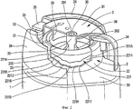
фиг.1 - вид в перспективе с частичным разрезом устройства дозировки текучего вещества, оборудованного дозировочной головкой в соответствии с настоящим изобретением;figure 1 is a perspective view in partial section of a device for dispensing a fluid substance equipped with a dosing head in accordance with the present invention;
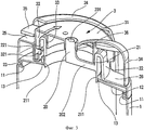
фиг.2 - увеличенный вид дозировочной головки, показанной на фиг.1;figure 2 is an enlarged view of the dosage head shown in figure 1;
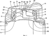
фиг.3 - вид в перспективе в вертикальном поперечном разрезе дозировочной головки, показанной на фиг.1 и 2, в закрытом положении;figure 3 is a perspective view in vertical transverse section of the dosage head shown in figures 1 and 2, in the closed position;
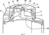
фиг.4 - вид, аналогичный фиг.3, в одном открытом положении;figure 4 is a view similar to figure 3, in one open position;
фиг.5 - вид, аналогичный фиг.4, в другом открытом положении.figure 5 is a view similar to figure 4, in another open position.
Устройство дозировки текучего вещества, оборудованное дозировочной головкой в соответствии с настоящим изобретением, содержит емкость 1, содержащую текучее вещество, например соль, крем или шампунь. Как правило, текучее вещество может быть жидким, гранулированным или порошкообразным. На своем верхнем конце емкость 1 содержит защелкивающийся паз 11, заплечик 12, выполненный радиально внутрь и заканчивающийся горловиной 13. Горловина 13 ограничивает отверстие, позволяющее извлекать текучее вещество, содержащееся в емкости. В рамках настоящего изобретения емкость не является определяющим компонентом: она может иметь любые размер и форму. Даже защелкивающийся паз 11, а также заплечик 12 и горловину 13 можно выполнять в разной конфигурации, не выходя при этом за рамки настоящего изобретения.A fluid metering device equipped with a metering head in accordance with the present invention comprises a
В данном случае на емкости 1 установлена дозировочная головка, содержащая два составных элемента, а именно: основание 2 и поворотный приводной элемент 3. В данном случае основание 2 установлено на емкости 1, однако, можно предусмотреть моноблочное выполнение основания 2 заодно с емкостью 1. В данном случае дозировочная головка состоит из двух элементов, однако, не исключено, что она может содержать и другие составные элементы в некоторых вариантах выполнения, не выходящих за рамки настоящего изобретения. Все же наиболее предпочтительным является пример с двумя составными элементами как с точки зрения формования, так с точки зрения сборки.In this case, a dispensing head is installed on the
Как показано на фигурах, основание 2 содержит внутреннюю муфту 21, содержащую нижнюю концевую часть 211, находящуюся в герметичном контакте с горловиной 13. В данном случае речь идет о статичном герметичном контакте с учетом того, что основание 2 предназначено для неподвижной установки на емкости 1. Муфта 21 ограничивает внутренний канал, непосредственно сообщающийся с внутренним объемом емкости 1, поскольку муфта находится внутри горловины 13. Игла 20, содержащая наружный верхний конец 201, установлена в центре и вокруг оси внутри муфты 21. Крепежные перемычки 202 соединяют внутреннюю стенку муфты 21 с иглой 20. Предпочтительно игла 20 содержит цилиндрическую наружную стенку, выполненную, начиная от ее верхнего конца 201. На уровне своего верхнего конца муфта 21 соединена с венцом 22, выполненным коаксиально вокруг муфты 21. Как показано на фигурах, в частности, на фиг.2, венец 22 содержит несколько окон 221, образующих отверстия в стенке венца 22. Эти окна 221, в данном случае в количестве трех, образуют направляющую дорожку. Окна распределены на одинаковом угловом расстоянии по периферии венца 22. Каждое окно 221 выполнено по существу в виде шеврона с заострением, направленным вниз. Таким образом, каждое окно 221 определяет первую оконную секцию 2211 и вторую оконную секцию 2212. Каждая секция выполнена в виде практически прямолинейной щели или рампы, наклоненной относительно горизонтальной или вертикальной плоскости. Так, каждая секция содержит наклонный участок 2215, 2216 определенной длины, определенного профиля и с определенным углом наклона. Углы наклона двух наклонных участков могут быть одинаковыми, но предпочтительно в соответствии с настоящим изобретением углы наклона этих двух наклонных участков отличаются друг от друга. Действительно, первая секция 2211 имеет угол наклона меньше угла наклона второй оконной секции 2212. С другой стороны, оконные секции 2211 и 2212 соединены друг с другом на уровне нижней точки 2210. С противоположных сторон каждая оконная секция содержит упорный конец 2213 и 2214, определяющий крайнюю точку оконных секций. В данном случае упорные концы 2213 и 2214 равноудалены от нижней точки 2210 таким образом, чтобы каждая оконная секция имела одинаковую длину. Учитывая, что углы наклона наклонных участков оконный секций отличаются друг от друга, а их длины одинаковы, упорные концы 2213 и 2214 не располагаются в одной и той же плоскости, а, наоборот, смещены в осевом направлении. Учитывая, что угол наклона наклонных участков второй секции 2212 больше угла наклона наклонных участков первой секции 2211, упорный конец 2214 расположен выше в осевом направлении, чем упорный конец 2213. Такое осевое смещение упорных концов двух оконных секций можно также получить при одинаковых углах наклона, но при разных длинах наклонных участков оконных секций. Действительно, при выполнении одной оконной секции 2212 более длинной, чем оконная секция 2211, но с одинаковым углом наклона, упорный конец 2214 будет смещен в осевом направлении вверх относительно упорного конца 2213. Следовательно, осевое смещение упорных концов окон 221 можно получить, изменяя либо угол наклона наклонных участков оконных секций, либо длину наклонных участков оконный секций. Можно также предусмотреть комбинацию из разных длин и разных углов наклона. Вместе с тем, в соответствии с настоящим изобретением не исключено расположение упорных концов окон в одной и той же плоскости. Тем не менее, предпочтительно все же выполнять эти концы смещенными.As shown in the figures, the
На фиг.2 можно также заметить, что каждый из наклонных участков 2215 и 2216 образует уступ 2217 и 2218, прерывающий линейность наклонного участка. Эти уступы, выступы или ступени определяют промежуточные положения между нижней точкой 2210 и упорными концами 2213 и 2214.2, you can also notice that each of the
Основание 2 имеет вокруг венца 22 сложную форму, неравномерную относительно контура венца. В данном случае основание содержит два сплошных контрфорса 24, образованных, с одной стороны, нижней нишей 25 и, с другой стороны, площадкой 26. Ниша 25 расположена ниже уровня контрфорсов 24, а площадка 26 расположена также ниже уровня контрфорсов 25 на высоте, меньшей высоты расположения ниши 25. Можно также заметить, что ниша 25 расположена по существу диаметрально противоположно площадке 26. Ниша 25 выполнена по угловому расстоянию примерно 10-30°, тогда как площадка 26 выполнена на угловом расстоянии более 90°. На уровне своей нижней наружной периферии основание содержит также защелкивающийся поясок 23, предназначенный для взаимодействия с защелкивающимся пазом 11, выполненным на емкости 1. Таким образом, основание 2 устанавливают неподвижно на емкости 1 на уровне паза 11, причем герметично за счет герметичного вхождения нижней концевой части 211 муфты 21 в горловину 13.The
Поворотный приводной элемент 3 в данном случае выполнен в виде колпачка, содержащего поворотную запорную площадку 31, в центре которой выполнено дозировочное отверстие 30. По нижней периферии дозировочного отверстия 30 площадка 31 содержит колонку 36 осевого направления, расположенную вокруг иглы 20 на определенной высоте. В данном случае колонка 36 состоит из нескольких лапок, соединяющих периферию дозировочного отверстия 30 со скребковым кольцом 362. Таким образом, колонка определяет несколько каналов 363 между каждой лапкой 361. Это показано на фиг.4, на которой верхний конец 201 иглы 20 смещен вниз относительно площадки 31, высвобождая, таким образом, каналы 363. Понятно, что эти каналы 363 образуют канал сообщения между внутренним пространством, образованным муфтой 21, непосредственно сообщающейся с емкостью, и наружным пространством головки. Таким образом, текучее вещество, содержащееся в емкости 1, может вытекать через дозировочное отверстие 30, проходя через каналы 363, когда иглу 20 перемещают внутрь головки. Направляющая и скользящая колонка 36 позволяют не только удерживать иглу 20 на оси вращения головки, но и очищать иглу 20 при каждом повороте приводного элемента за счет скребкового эффекта, достигаемого при перемещении иглы в колонке. В этом скребковом действии участвует кольцо 362, а также лапки 361.The
На уровне своей наружной периферии площадка 31 продолжена юбкой 32, направленной вниз. Эта юбка 32 расположена концентрично вокруг венца 22. В данном примере юбка 32 содержит три шипа 321, которые заходят в соответствующие окна 221, выполненные в венце 22. На фиг.1 показан один шип и одно окно. Однако юбка 32 может содержать три шипа 321, равномерно выполненных и находящихся друг от друга на угловом расстоянии в 120° на периферии внутренней стенки юбки 32. Учитывая, что каждый шип 321 заходит в соответствующее окно 221, и это окно имеет профиль с двумя идентичными или разными наклонными участками, поворот приводного элемента 3 на основании 2 приводит к перемещению шипов в окнах соответственно профилю наклонных участков. Когда шипы 321 находятся на уровне нижних точек 2210 окон 221, поворотный приводной элемент 3 находится в своей самой нижней точке относительно основания 2. В этом случае игла 20 находится в своей самой верхней точке в направляющей скребковой колонке 36. Это соответствует закрытому положению дозировочной головки, показанной на фиг.1, 2 и 3, в котором верхний конец 201 иглы 20 находится предпочтительно герметично в дозировочном отверстии 30. Можно также заметить, что верхний конец 201 находится по существу в той же плоскости, что и площадка 31. При перемещении поворотом по часовой стрелке или против часовой стрелки приводного элемента 3 на основании 2 шипы перемещаются в одной из двух оконных секций, выполненных в окнах. В этом случае шипы следуют по наклонным участкам направляющих дорожек, ограниченных оконными секциями. Таким образом, поворотный приводной элемент 3 можно вращать до момента, когда шипы приходят в положение упора в упорные концы 2213 или 2214 в зависимости от того, поворачивают ли элемент 3 по часовой стрелке или против часовой стрелки. В обоих случаях шип вынужден перемещаться в осевом направлении вверх за счет конфигурации оконных секций 2211 в виде шеврона, заострение которого направлено вниз. В результате этого площадка 31 поднимается и вместе с ней поднимается дозировочное отверстие 30, тогда как игла 20 остается неподвижной. Визуально игла 20 углубляется в колонку 36, открывая каналы 363. Когда шипы приходят в положение упора в упорные концы, дозировочная головка достигает открытого положения. Понятно, что другое открытое положение может быть достигнуто, когда шипы приходят в положение упора в другие упорные концы окон. Следовательно, имеются два крайних открытых положения, которые соответствуют двум положениям углубления иглы 20 в колонку 36. Можно также говорить о выходе иглы 20 из дозировочного отверстия 30. Когда упорные концы 2213 и 2214 находятся в одной горизонтальной плоскости, то есть когда между упорными концами нет осевого смещения, игла углубляется или выходит одинаково и на одно и то же расстояние в двух открытых положениях. И, наоборот, когда упорные концы 2213 и 2214 смещены в осевом направлении, как в наиболее предпочтительном варианте выполнения настоящего изобретения, два открытых положения соответствуют двум разным положениям углубления иглы 20 относительно дозировочного отверстия 30. Это можно заметить, сравнив фиг.4 и 5, где дозировочная головка показана в этих двух разных открытых положениях. Можно легко заметить, что каналы 363 на фиг.4 открыты в меньшей степени, чем на фиг.5. Это объясняется тем, что игла 20 на фиг.5 заходит глубже в колонку 36, чем на фиг.4. В результате расход потока текучего вещества через единое дозировочное отверстие 30 является более значительным в открытом положении, соответствующем фиг.5, чем в открытом положении, показанном на фиг.4.At the level of its outer periphery, the
Предпочтительно уступы 2217 и 2218, образованные наклонными участками 2215 и 2216, определяют устойчивые промежуточные открытые положения, соответствующие фиксированному промежуточному расходу потока. Таким образом, при помощи только одного окна можно получить два крайних положения, разделенных несколькими фиксированными промежуточными открытыми положениями и, по меньшей мере, одним фиксированным промежуточным закрытым положением. Действительно, можно предусмотреть несколько закрытых положений и более двух промежуточных открытых положений или, наоборот, только одно промежуточное открытое положение на одном из двух наклонных участков.Preferably, the
Более или менее выраженное углубление иглы 20 в колонке 36 и, соответственно, в дозировочном отверстии 30 позволяет менять расход потока текучего вещества. С другой стороны, захождение шипов в окна одновременно обеспечивает осевое перемещение и направление при вращении.A more or less pronounced recess of the
Можно также заметить, что поворотный приводной элемент 3 содержит уплотнительную кромку 33, входящую в герметичный контакт при вращении в муфте 21. Таким образом, обеспечивается идеальная динамическая герметичность дозировочной головки. С другой стороны, приводной элемент 3 содержит также приводную кнопку 34, помогающую поворачивать элемент 3. Эта приводная кнопка 34 находится на уровне площадки 26 между двумя контрфорсами 24. Когда кнопка 34 упирается в задний контрфорс, как показано на фиг.4, дозировочная головка находится в открытом положении малого расхода. Когда же приводная кнопка 34 упирается в другой контрфорс 24, показанный на переднем плане на фиг.5, дозировочная головка находится в открытом положении большого расхода.You can also notice that the
Согласно другому отличительному признаку поворотный приводной элемент содержит также средства защиты первого использования, представляющие собой язычок 35, выполненный моноблочно вместе с остальной частью приводного элемента 3 и расположенный на уровне ниши 25. Предпочтительно язычок 35 выполняют по всей ширине ниши 25 таким образом, чтобы приходить в положение упора в два смежных контрфорса 24. Благодаря этому поворотный приводной элемент 3 блокируется от вращения в закрытом положении. Это показано на фиг.2, а также на фиг.3. Для приведения в действие дозировочной головки необходимо сначала оторвать язычок 35.According to another distinguishing feature, the rotary drive element also comprises first-use protection means, which are a
Благодаря настоящему изобретению получают дозировочную головку с двумя одинаковыми или, предпочтительно, разными открытыми положениями по обе стороны от промежуточного или даже центрального закрытого положения. Средства перемещения, использующие взаимодействие между шипами и окнами, выполненными в виде шевронов, могут быть выполнены в виде некоего подобия резьбы с нитками в виде шевронов с одинаковыми или разными углами наклона наклонных участков и с одинаковой или разной длиной наклонных участков.Thanks to the present invention, a dosing head is obtained with two identical or, preferably, different open positions on both sides of the intermediate or even central closed position. Means of movement using the interaction between the spikes and windows made in the form of chevrons can be made in the form of a kind of thread with threads in the form of chevrons with the same or different angles of inclination of the inclined sections and with the same or different length of the inclined sections.
Claims (10)
Applications Claiming Priority (2)
| Application Number | Priority Date | Filing Date | Title |
|---|---|---|---|
| FR0308626A FR2857653B1 (en) | 2003-07-15 | 2003-07-15 | HEAD OF DISTRIBUTION OF FLUID PRODUCT |
| FR0308626 | 2003-07-15 |
Publications (2)
| Publication Number | Publication Date |
|---|---|
| RU2006104626A RU2006104626A (en) | 2007-08-20 |
| RU2352507C2 true RU2352507C2 (en) | 2009-04-20 |
Family
ID=33548147
Family Applications (1)
| Application Number | Title | Priority Date | Filing Date |
|---|---|---|---|
| RU2006104626/12A RU2352507C2 (en) | 2003-07-15 | 2004-07-13 | Head to meter out fluid substances |
Country Status (14)
| Country | Link |
|---|---|
| US (1) | US7748580B2 (en) |
| EP (1) | EP1656304B1 (en) |
| JP (1) | JP2007516135A (en) |
| CN (1) | CN100488849C (en) |
| AU (1) | AU2004256950B2 (en) |
| BR (1) | BRPI0412294A (en) |
| CA (1) | CA2532900A1 (en) |
| CZ (1) | CZ200621A3 (en) |
| DE (1) | DE602004004795T2 (en) |
| ES (1) | ES2281006T3 (en) |
| FR (1) | FR2857653B1 (en) |
| PL (1) | PL202697B1 (en) |
| RU (1) | RU2352507C2 (en) |
| WO (1) | WO2005007534A2 (en) |
Families Citing this family (5)
| Publication number | Priority date | Publication date | Assignee | Title |
|---|---|---|---|---|
| ES2254038B1 (en) * | 2005-12-22 | 2007-02-16 | Comercial Valira S.A. | PLUG WITH AUTOMATIC BROCAL. |
| AT507950B1 (en) | 2009-02-23 | 2011-07-15 | Xolution Gmbh | COVER OF A CONTAINER |
| US8141793B2 (en) * | 2009-07-14 | 2012-03-27 | The Dial Corporation | Gel air freshener and method of unsealing such gel air freshener |
| FR2978737B1 (en) * | 2011-08-01 | 2013-08-30 | Maitrise & Innovation | ANTI-DROP CAP WITH AUTOMATIC AND HIGH-SEAL MOBILE HOOD |
| CN110271766B (en) * | 2019-04-30 | 2020-07-21 | 嘉兴市龙骏信息科技有限公司 | Liquid glue containing bottle |
Family Cites Families (12)
| Publication number | Priority date | Publication date | Assignee | Title |
|---|---|---|---|---|
| US2533915A (en) * | 1945-05-07 | 1950-12-12 | Chester A Brooks | Rotatable closure structure having yieldable locking means |
| US3231155A (en) * | 1964-03-23 | 1966-01-25 | Paul H Mcconnell | Container and closure cap therefor |
| FR1520693A (en) * | 1967-03-01 | 1968-04-12 | Oreal | New closure device for vials or similar containers |
| US4424918A (en) * | 1981-10-16 | 1984-01-10 | Gene Stull | Non-resealable dispenser cap construction |
| BE905791A (en) * | 1986-11-19 | 1987-03-16 | Lynes Holding Sa | POURING CAP. |
| US4842169A (en) * | 1987-02-03 | 1989-06-27 | Gene Stull | Twist cap having adjustable flow rate |
| US4823994A (en) * | 1987-02-25 | 1989-04-25 | Laauwe Robert H | Speciality closures for bottle necks |
| US5000360A (en) * | 1989-09-27 | 1991-03-19 | John Lown | Pouring spout which can be selectively opened and closed |
| US5429282A (en) * | 1994-03-31 | 1995-07-04 | Erie Plastics | Multi-position self-guiding closure for a container |
| FR2760724B1 (en) * | 1997-03-14 | 1999-04-30 | Oreal | CONTAINER TYPE WITH CAPSULE MOUNTED BY CLICKING |
| US6135318A (en) * | 1997-10-08 | 2000-10-24 | Stull Technologies | Variable rate closure for dispensers having fluid contents |
| US6675995B2 (en) * | 2000-06-05 | 2004-01-13 | Stull Technologies, Inc. | Traversing twist cap |
-
2003
- 2003-07-15 FR FR0308626A patent/FR2857653B1/en not_active Expired - Fee Related
-
2004
- 2004-07-13 CZ CZ20060021A patent/CZ200621A3/en unknown
- 2004-07-13 AU AU2004256950A patent/AU2004256950B2/en not_active Expired - Fee Related
- 2004-07-13 EP EP04767674A patent/EP1656304B1/en not_active Expired - Fee Related
- 2004-07-13 BR BRPI0412294-1A patent/BRPI0412294A/en not_active IP Right Cessation
- 2004-07-13 CN CNB2004800234920A patent/CN100488849C/en not_active Expired - Fee Related
- 2004-07-13 US US10/564,163 patent/US7748580B2/en not_active Expired - Fee Related
- 2004-07-13 WO PCT/FR2004/001845 patent/WO2005007534A2/en active IP Right Grant
- 2004-07-13 CA CA002532900A patent/CA2532900A1/en not_active Abandoned
- 2004-07-13 ES ES04767674T patent/ES2281006T3/en active Active
- 2004-07-13 JP JP2006519959A patent/JP2007516135A/en active Pending
- 2004-07-13 PL PL379289A patent/PL202697B1/en not_active IP Right Cessation
- 2004-07-13 RU RU2006104626/12A patent/RU2352507C2/en not_active IP Right Cessation
- 2004-07-13 DE DE602004004795T patent/DE602004004795T2/en active Active
Also Published As
| Publication number | Publication date |
|---|---|
| DE602004004795T2 (en) | 2007-11-22 |
| FR2857653A1 (en) | 2005-01-21 |
| CA2532900A1 (en) | 2005-01-27 |
| DE602004004795D1 (en) | 2007-03-29 |
| RU2006104626A (en) | 2007-08-20 |
| AU2004256950B2 (en) | 2010-06-17 |
| ES2281006T3 (en) | 2007-09-16 |
| JP2007516135A (en) | 2007-06-21 |
| CN1849247A (en) | 2006-10-18 |
| AU2004256950A1 (en) | 2005-01-27 |
| US20070017937A1 (en) | 2007-01-25 |
| US7748580B2 (en) | 2010-07-06 |
| EP1656304A2 (en) | 2006-05-17 |
| EP1656304B1 (en) | 2007-02-14 |
| PL379289A1 (en) | 2006-08-21 |
| CN100488849C (en) | 2009-05-20 |
| WO2005007534A3 (en) | 2005-04-14 |
| BRPI0412294A (en) | 2006-09-19 |
| PL202697B1 (en) | 2009-07-31 |
| CZ200621A3 (en) | 2007-01-31 |
| FR2857653B1 (en) | 2008-03-28 |
| WO2005007534A2 (en) | 2005-01-27 |
Similar Documents
| Publication | Publication Date | Title |
|---|---|---|
| US5509582A (en) | Dispensing cap with internal measuring chamber | |
| RU2662385C2 (en) | Containers and methods for isolating liquids prior to dispensing | |
| US7543724B2 (en) | Dispensing system with a dispensing valve having a projecting, reduced size discharge end | |
| PL200210B1 (en) | Twist operable dispensing closure accommodating optional liner puncture feature | |
| US5429282A (en) | Multi-position self-guiding closure for a container | |
| EP0598223B1 (en) | Dispenser cap for a fluid substance container, with a movable dispensing nozzle | |
| US4754899A (en) | Twist cap having adjustable flow rate | |
| US6450352B1 (en) | Child-resistant push and twist locking cap | |
| US4405306A (en) | Medicated disposable douche product | |
| US20070295764A1 (en) | Flexible, elongate dispensing valve | |
| KR20110036660A (en) | Container caps and systems | |
| CN110062738B (en) | Closure with spout and device for introducing an additive into a beverage container | |
| CA2281536C (en) | Dispensing closure | |
| US20140312075A1 (en) | Dispenser with discharge control | |
| RU2352507C2 (en) | Head to meter out fluid substances | |
| US5890633A (en) | Two component, molded plastic dispenser operating on push-pull principle | |
| US6513681B2 (en) | Spray closure with a push-pull seal | |
| CN113423652B (en) | Device for packaging two products separately | |
| EP0701523B1 (en) | Clog-resistant toggle disk closure | |
| CA2118363A1 (en) | Hand-held dispenser with twist-to-open cap | |
| US4022464A (en) | Dispensing container and closure | |
| US5090598A (en) | Dispenser construction | |
| RU2667633C2 (en) | Dosing dispensing closure | |
| CA2136060A1 (en) | Spray-type dispenser cap construction | |
| CA2192808C (en) | Dispenser cap for containers |
Legal Events
| Date | Code | Title | Description |
|---|---|---|---|
| MM4A | The patent is invalid due to non-payment of fees |
Effective date: 20110714 |