EP1655524A1 - Dichtung - Google Patents
Dichtung Download PDFInfo
- Publication number
- EP1655524A1 EP1655524A1 EP04026239A EP04026239A EP1655524A1 EP 1655524 A1 EP1655524 A1 EP 1655524A1 EP 04026239 A EP04026239 A EP 04026239A EP 04026239 A EP04026239 A EP 04026239A EP 1655524 A1 EP1655524 A1 EP 1655524A1
- Authority
- EP
- European Patent Office
- Prior art keywords
- sensor
- opening
- support ring
- seal according
- spring element
- Prior art date
- Legal status (The legal status is an assumption and is not a legal conclusion. Google has not performed a legal analysis and makes no representation as to the accuracy of the status listed.)
- Granted
Links
Images


Classifications
-
- F—MECHANICAL ENGINEERING; LIGHTING; HEATING; WEAPONS; BLASTING
- F16—ENGINEERING ELEMENTS AND UNITS; GENERAL MEASURES FOR PRODUCING AND MAINTAINING EFFECTIVE FUNCTIONING OF MACHINES OR INSTALLATIONS; THERMAL INSULATION IN GENERAL
- F16J—PISTONS; CYLINDERS; SEALINGS
- F16J15/00—Sealings
- F16J15/16—Sealings between relatively-moving surfaces
- F16J15/32—Sealings between relatively-moving surfaces with elastic sealings, e.g. O-rings
- F16J15/3248—Sealings between relatively-moving surfaces with elastic sealings, e.g. O-rings provided with casings or supports
- F16J15/3252—Sealings between relatively-moving surfaces with elastic sealings, e.g. O-rings provided with casings or supports with rigid casings or supports
-
- F—MECHANICAL ENGINEERING; LIGHTING; HEATING; WEAPONS; BLASTING
- F16—ENGINEERING ELEMENTS AND UNITS; GENERAL MEASURES FOR PRODUCING AND MAINTAINING EFFECTIVE FUNCTIONING OF MACHINES OR INSTALLATIONS; THERMAL INSULATION IN GENERAL
- F16J—PISTONS; CYLINDERS; SEALINGS
- F16J15/00—Sealings
- F16J15/16—Sealings between relatively-moving surfaces
- F16J15/32—Sealings between relatively-moving surfaces with elastic sealings, e.g. O-rings
- F16J15/3248—Sealings between relatively-moving surfaces with elastic sealings, e.g. O-rings provided with casings or supports
- F16J15/3252—Sealings between relatively-moving surfaces with elastic sealings, e.g. O-rings provided with casings or supports with rigid casings or supports
- F16J15/3256—Sealings between relatively-moving surfaces with elastic sealings, e.g. O-rings provided with casings or supports with rigid casings or supports comprising two casing or support elements, one attached to each surface, e.g. cartridge or cassette seals
- F16J15/326—Sealings between relatively-moving surfaces with elastic sealings, e.g. O-rings provided with casings or supports with rigid casings or supports comprising two casing or support elements, one attached to each surface, e.g. cartridge or cassette seals with means for detecting or measuring relative rotation of the two elements
Definitions
- the invention relates to a seal, comprising a support ring with at least one inner peripheral side fixed to the support ring sealing lip, wherein on the support ring of the same material and integrally a sensor holder for receiving a sensor is arranged.
- seals are known from DE 200 00 694 U1.
- the previously known seal comprises a sealing flange with dynamically and statically sealing sealing elements.
- the sealing flange has for the attachment of functional elements, such as sensors, spring elements which are firmly connected to the sealing flange.
- the spring elements engage in the determination of the functional elements in corresponding recesses on the functional element.
- the invention has for its object to provide a seal that is simple and inexpensive to produce and on the simple means a sensor can be attached.
- the sensor holder has at least one opening for receiving the sensor and the sensor has for releasable attachment in the sensor holder at least one spring element which can be latched in the opening of the sensor holder.
- An opening can be easily and inexpensively provided in the support ring, whereby the production of the seal is easy and inexpensive.
- the mounting of the sensor is particularly simple, since the sensor is merely inserted into the opening and a captive attachment is achieved by the spring elements, which engage in also in the opening.
- the spring elements also result in a play-free connection between the sensor and the support ring, which increases the accuracy of the system consisting of an encoder, the shaft to be sealed, the seal and attached to the seal sensor. Due to the detachable attachment of the sensor, a subsequent exchange of the sensor is possible, for example, if the sensor wears prematurely. Installation is very easy and the use of special tools is avoided because the sensor is only inserted into the opening. As a result, the sensor is easy to install even in difficult to reach seals.
- the connection is special safe, because the sensor audibly engages when the spring element engages behind the undercut of the opening.
- the support ring may be formed of a metallic material.
- Metallic materials have a high strength and are inexpensive. They are easy to transform.
- the support ring may be a stamped part. Stamped support rings are inexpensive and easy to produce with few manufacturing steps and in large quantities. For punching semi-finished products made of metallic materials are particularly suitable.
- the sensor holder may have at least two openings, wherein the first opening forms the receptacle for the sensor and the second opening forms the receptacle for the spring element of the sensor.
- the separate receptacles for the sensor and the spring element results in a particularly play-free connection of the support ring and sensor.
- the sensor holder may have three juxtaposed openings, wherein the first opening forms the receptacle for the sensor and the second and the third opening form the receptacles for the spring elements of the sensor, wherein the first opening between the second and the third opening is arranged. Due to the additional opening for a further spring element, the attachment of the sensor, in particular the tipping stability, is further improved.
- the spring element may be formed by a spring clip.
- Spring clips are simple and inexpensive to produce. With spring clips safe and easy to install connections can be made. Spring clips can be easily attached to the sensor.
- the spring clip may be formed of a metallic material.
- the spring clip may be made of spring steel, for example.
- the spring element may be formed by a snap hook made of polymeric material. Snap hooks are inexpensive and easy to produce.
- the snap hook can be formed of the same material and in one piece with the sensor. As a result, the production of sensor and snap hook can be done inexpensively in one production step.
- the support ring may have a first axial leg and a radial projection extending radially outwards from the free end face of the first axial leg, which may have a second axial leg on the side facing away axially from the first axial leg, wherein the sensor support is arranged on the second axial leg.
- the radial projection simplifies the installation of the seal, since the radial projection serves as a stop. The inclusion of sensors with a large radial extent is also possible.
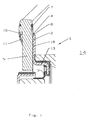
- Figure 1 shows a seal 1 with a support ring 2, on the inner peripheral side a dynamically stressed sealing lip 3 is fixed.
- the sealing lip 3 is formed of PTFE and pre-stretched with its free end against the direction of the space to be sealed.
- the support ring 2 has a first axial leg 13 at its free end side, a radially outwardly extending radial projection 16 is arranged.
- a second axial leg 15 is arranged on the first axial leg 13 axially facing away from the radial projection 16, a second axial leg 15 is arranged.
- the sensor holder 4 is arranged at the second axial leg 15, the sensor holder 4 is arranged.
- the sensor holder 4 is formed of the same material and integrally on the support ring 2 and has for receiving a sensor 5, an opening 8.
- the sensor 5 in turn has for releasable attachment in the opening 8 of the sensor holder 4, a spring element 7.
- the spring element 7 is designed as a spring clip 11 and made of spring steel. To fix the sensor 5, the spring element 7 audibly engages in the opening.
- the support ring 2 is made of a metallic material and is produced by stamping.
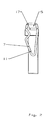
- Figure 2 shows a sensor 5 with a spring element 7.
- the spring element 7 is formed in this embodiment by a spring clip 11 and consists of Spring steel.
- the spring clip 11 is arranged in a groove 17 which extends at least partially annularly around the sensor 5.
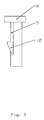
- Figure 3 shows another embodiment of a sensor 5 with a spring element 7.
- the spring element 7 is formed in this embodiment by a snap hook 12 and consists of a polymeric material.
- the snap hook is in this embodiment in one piece and formed of the same material with the sensor 5.
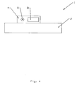
- FIG. 4 shows a carrier ring 2 with the sensor holder 4 according to the invention.
- the sensor holder 4 has two apertures 8, 9.
- the first opening 8 forms the receptacle for the sensor 5
- the second opening 9 forms the receptacle for the spring element 7 of the sensor fifth
- FIG. 5 shows another embodiment of a carrier ring 2 with the sensor holder 4 according to the invention.
- the sensor holder 4 has three apertures 8, 9, 10 arranged next to one another.
- the first opening 8 forms the receptacle for the sensor 5 and the second and the third opening 9, 10 form the receptacle for the spring elements 7 of the sensor 5.
- the first opening 8 is arranged between the second and the third opening 9, 10.
- Figure 6 shows a further embodiment of a support ring 2 with the sensor holder 4 according to the invention.
- the support ring 2 and the sensor holder 4 are integrally molded or molded of a plastic material of a plastic.
- the support ring 2 has the shape of a housing closure cover and carries out of the sealing lip 3 a statically acting seal 18.
- the aperture 8 is for receiving a Sensor 5 and the opening 9 for receiving a spring clip 11 is provided.
- Figure 7 shows a further embodiment of a support ring 2 with the sensor holder according to the invention 4.
- the support ring 2 and the sensor holder 4 are designed in one piece and of the same material.
- the spring element is formed by a helical compression spring. This is on the one hand in a recess 21 on the sensor 5 and on the other hand in an opening 19 of an adjacent component 20 latched. As a result, the sensor 5 is pressed captive into the sensor holder.
- the helical compression spring simultaneously protects the electrical leads from mechanical injury.
Landscapes
- Engineering & Computer Science (AREA)
- General Engineering & Computer Science (AREA)
- Mechanical Engineering (AREA)
- Sealing With Elastic Sealing Lips (AREA)
- Snaps, Bayonet Connections, Set Pins, And Snap Rings (AREA)
- Investigating Or Analyzing Materials By The Use Of Fluid Adsorption Or Reactions (AREA)
- Clamps And Clips (AREA)
- Transmission And Conversion Of Sensor Element Output (AREA)
- Crystals, And After-Treatments Of Crystals (AREA)
- Piezo-Electric Or Mechanical Vibrators, Or Delay Or Filter Circuits (AREA)
Abstract
Description
- Die Erfindung betrifft eine Dichtung, umfassend einen Tragring mit zumindest einer innenumfangsseitig am Tragring festgelegten Dichtlippe, wobei an dem Tragring materialeinheitlich und einstückig eine Sensorhalterung zur Aufnahme eines Sensors angeordnet ist.
- Derartige Dichtungen sind aus der DE 200 00 694 U1 bekannt. Die vorbekannte Dichtung umfasst einen Dichtflansch mit dynamisch und statisch dichtenden Dichtungselementen. Der Dichtflansch weist zur Befestigung von Funktionselementen, beispielsweise Sensoren, Federelemente auf, die fest mit dem Dichtflansch verbunden sind. Die Federelemente greifen zur Festlegung der Funktionselemente in korrespondierende Ausnehmungen am Funktionselement ein.
- Der Erfindung liegt die Aufgabe zugrunde, eine Dichtung bereitzustellen, die einfach und kostengünstig herstellbar ist und an der mit einfachen Mitteln ein Sensor befestigt werden kann.
- Die Aufgabe wird mit den Merkmalen von Anspruch 1 gelöst. Auf vorteilhafte Ausgestaltungen nehmen die Unteransprüche Bezug.
- Zur Lösung der Aufgabe weist die Sensorhalterung zumindest eine Durchbrechung zur Aufnahme des Sensors auf und der Sensor weist zur lösbaren Befestigung in der Sensorhalterung zumindest ein Federelement auf, das in der Durchbrechung der Sensorhalterung einrastbar ist.
- Eine Durchbrechung kann einfach und kostengünstig in dem Tragring vorgesehen werden, wodurch die Herstellung der Dichtung einfach und kostengünstig ist. Die Montage des Sensors ist besonders einfach, da der Sensor lediglich in die Durchbrechung eingesteckt wird und durch die Federelemente, die in ebenfalls in der Durchbrechung einrasten, eine verliersichere Befestigung erreicht wird. Durch die Federelemente ergibt sich zudem eine spielfreie Verbindung zwischen Sensor und Tragring, wodurch sich die Messgenauigkeit des System bestehend aus einem Encoder, der abzudichtenden Welle, der Dichtung und dem an der Dichtung befestigten Sensor erhöht. Durch die lösbare Befestigung des Sensors ist ein nachträgliches Austauschen des Sensors möglich, beispielsweise wenn der Sensor vorzeitig verschleißt. Die Montage erfolgt sehr einfach und die Verwendung von Spezialwerkzeug wird vermieden, da der Sensor lediglich in die Durchbrechung eingesteckt wird. Dadurch ist der Sensor auch in schwierig zu erreichende Dichtungen einfach montierbar. Die Verbindung ist besonders sicher, da der Sensor hörbar einrastet wenn das Federelement hinter der Hinterschneidung der Durchbrechung einrastet.
- Der Tragring kann aus einem metallischen Werkstoff gebildet sein. Metallische Werkstoffe weisen eine hohe Festigkeit auf und sind kostengünstig. Sie lassen sich leicht umformen.
- Der Tragring kann ein Stanzteil sein. Gestanzte Tragringe sind mit wenigen Herstellungsschritten und in großen Stückzahlen kostengünstig und einfach herstellbar. Zum Stanzen sind Halbzeuge aus metallischen Werkstoffen besonders geeignet.
- Die Sensorhalterung kann zumindest zwei Durchbrechungen aufweisen, wobei die erste Durchbrechung die Aufnahme für den Sensor bildet und die zweite Durchbrechung die Aufnahme für das Federelement des Sensors bildet. Durch die getrennten Aufnahmen für den Sensor und das Federelement ergibt sich eine besonders spielfreie Verbindung von Tragring und Sensor.
- Die Sensorhalterung kann drei nebeneinander angeordnete Durchbrechungen aufweisen, wobei die erste Durchbrechung die Aufnahme für den Sensor bildet und die zweite und die dritte Durchbrechung die Aufnahmen für die Federelemente des Sensors bilden, wobei die erste Durchbrechung zwischen der zweiten und der dritten Durchbrechung angeordnet ist. Durch die zusätzliche Durchbrechung für ein weiteres Federelement wird die Befestigung des Sensors, insbesondere die Kippstabilität, nochmals verbessert.
- Das Federelement kann durch eine Federklammer gebildet sein. Federklammern sind einfach und kostengünstig herstellbar. Mit Federklammern können sichere und einfach montierbare Verbindungen hergestellt werden. Federklammern können mit einfachen Mitteln am Sensor befestigt werden.
- Die Federklammer kann aus einem metallischen Werkstoff gebildet sein. Die Federklammer kann beispielsweise aus Federstahl gefertigt sein. Mittels einer Federklammer aus Federstahl kann eine hohe Federkraft erreicht werden, aus der dann entsprechend hohe Haltekräfte resultieren. Aus der hohen Haltekraft ergibt sich dann ein besonders spielfreie Verbindung von Tragring und Sensor.
- Das Federelement kann durch einen Schnapphaken aus polymerem Werkstoff gebildet sein. Schnapphaken sind kostengünstig und einfach herstellbar.
- Der Schnapphaken kann materialeinheitlich und einstückig mit dem Sensor ausgebildet sein. Dadurch kann die Herstellung von Sensor und Schnapphaken kostengünstig in einem Herstellungsschritt erfolgen.
- Der Tragring kann einen ersten Axialschenkel und einen sich von der freien Stirnseite des ersten Axialschenkels radial nach außen erstreckenden Radialvorsprung aufweisen, der auf der dem ersten Axialschenkel axial abgewandten Seite einen zweiten Axialschenkel aufweisen kann, wobei an dem zweiten Axialschenkel die Sensorhalterung angeordnet ist. Der Radialvorsprung vereinfacht die Montage der Dichtung, da der Radialvorsprung als Anschlag dient. Die Aufnahme von Sensoren mit einer großen radialen Erstreckung wird ebenfalls ermöglicht.
- Einige Ausführungsbeispiele der erfindungsgemäßen Dichtung werden nachfolgend anhand der Figuren näher erläutert. Es zeigen, jeweils in schematischer Darstellung:
- Fig. 1
- eine erfindungsgemäße Dichtung;
- Fig. 2
- einen Sensor mit einer Federklammer;
- Fig. 3
- einen Sensor mit einem Schnapphaken;
- Fig. 4
- eine Sensorhalterung mit zwei Durchbrechungen in der Draufsicht;
- Fig. 5
- eine Sensorhalterung mit drei Durchbrechungen in der Draufsicht;
- Fig. 6
- eine erfindungsgemäße Dichtungsanordnung aus einem Kunststoff;
- Fig. 7
- eine erfindungsgemäße Dichtungsanordnung, wobei das Federelement durch eine Schraubendruckfeder gebildet ist.
- Figur 1 zeigt eine Dichtung 1 mit einem Tragring 2, an dem innenumfangsseitig eine dynamisch beanspruchte Dichtlippe 3 festgelegt ist. In dieser Ausführung ist die Dichtlippe 3 aus PTFE gebildet und mit ihren freien Ende entgegen der Richtung des abzudichtenden Raums 14 vorgestreckt. Der Tragring 2 weist einen ersten Axialschenkel 13 auf an dessen freier Stirnseite ein sich radial nach außen erstreckender Radialvorsprung 16 angeordnet ist. Auf der dem ersten Axialschenkel 13 axial abgewandten Seite des Radialvorsprungs 16 ist ein zweiter Axialschenkel 15 angeordnet. An dem zweiten Axialschenkel 15 ist die Sensorhalterung 4 angeordnet. Die Sensorhalterung 4 ist materialeinheitlich und einstückig am Tragring 2 ausgebildet und weist zur Aufnahme eines Sensors 5 eine Durchbrechung 8 auf. Der Sensor 5 wiederum weist zur lösbaren Befestigung in der Durchbrechung 8 der Sensorhalterung 4 ein Federelement 7 auf. Das Federelement 7 ist als Federklammer 11 ausgebildet und aus Federstahl gefertigt. Zur Befestigung des Sensors 5 rastet das Federelement 7 hörbar in der Durchbrechung ein. Der Tragring 2 besteht aus einem metallischen Werkstoff und ist im Stanzverfahren hergestellt.
- Figur 2 zeigt einen Sensor 5 mit einem Federelement 7. Das Federelement 7 ist in dieser Ausführung durch eine Federklammer 11 gebildet und besteht aus Federstahl. Die Federklammer 11 ist in einer Nut 17 angeordnet die sich zumindest teilweise ringförmig um den Sensor 5 erstreckt.
- Figur 3 zeigt eine andere Ausführung eines Sensors 5 mit einem Federelement 7. Das Federelement 7 ist in dieser Ausführung durch einen Schnapphaken 12 gebildet und besteht aus einem polymerem Werkstoff. Der Schnapphaken ist in dieser Ausführung einstückig und materialeinheitlich mit dem Sensor 5 ausgebildet.
- Figur 4 zeigt einen Tragring 2 mit der erfindungsgemäßen Sensorhalterung 4. In dieser Ausführung weist die Sensorhalterung 4 zwei Durchbrechungen 8, 9 auf. Dabei bildet die erste Durchbrechung 8 die Aufnahme für den Sensor 5 und die zweite Durchbrechung 9 bildet die Aufnahme für das Federelement 7 des Sensors 5.
- Figur 5 zeigt eine andere Ausgestaltung eines Tragrings 2 mit der erfindungsgemäßen Sensorhalterung 4. In dieser Ausführung weist die Sensorhalterung 4 drei nebeneinander angeordnete Durchbrechungen 8, 9, 10 auf. Dabei bildet die erste Durchbrechung 8 die Aufnahme für den Sensor 5 und die zweite und die dritte Durchbrechung 9 ,10 bilden die Aufnahme für die Federelemente 7 des Sensors 5. Die erste Durchbrechung 8 ist zwischen der zweiten und der dritten Durchbrechung 9, 10 angeordnet.
- Figur 6 zeigt eine weitere Ausgestaltung eines Tragrings 2 mit der erfindungsgemäßen Sensorhalterung 4. In dieser Ausführung sind der Tragring 2 und die Sensorhalterung 4 einstückig und materialeinheitlich aus einem Kunststoff gegossen oder gespritzt. Der Tragring 2 hat die Gestalt eines Gehäuseverschlussdeckels und trägt außer der Dichtlippe 3 eine statisch wirkende Dichtung 18. Die Durchbrechung 8 ist für die Aufnahme eines Sensors 5 und die Durchbrechung 9 für die Aufnahme einer Federklammer 11 vorgesehen.
- Figur 7 zeigt eine weitere Ausgestaltung eines Tragrings 2 mit der erfindungsgemäßen Sensorhalterung 4. in dieser Ausführung sind der Tragring 2 und die Sensorhalterung 4einstückig und materialeinheitlich gestaltet. Das Federelement ist durch eine Schraubendruckfeder gebildet. Diese ist einerseits in einer Ausnehmung 21 am Sensor 5 und andererseits in einer Durchbrechung 19 eines benachbarten Bauteils 20 einrastbar. Dadurch ist der Sensor 5 verliersicher in die Sensorhalterung gedrückt. Die Schraubendruckfeder schützt gleichzeitig die elektrischen Leitungen vor mechanischen Verletzungen.
Claims (11)
- Dichtung (1), umfassend einen Tragring (2) mit zumindest einer innenumfangsseitig am Tragring (2) festgelegten Dichtlippe (3), wobei an dem Tragring (2) materialeinheitlich und einstückig eine Sensorhalterung (4) zur Aufnahme eines Sensors (5) angeordnet ist, dadurch gekennzeichnet, dass die Sensorhalterung (4) zumindest eine Durchbrechung (8) zur Aufnahme des Sensors (5) aufweist und dass der Sensor (5) zur lösbaren Befestigung in der Sensorhalterung (4) zumindest ein Federelement (7) aufweist, welches den Sensor verliersicher in der Sensorhalterung (4) fixiert.
- Dichtung nach Anspruch 1, dadurch gekennzeichnet, dass das Federelement in der Durchbrechung (8) der Sensorhalterung (4) einrastbar ist.
- Dichtung nach Anspruch 1 oder 2, dadurch gekennzeichnet, dass der Tragring (2) aus einem metallischen Werkstoff gebildet ist.
- Dichtung nach einem der Ansprüche 1 bis 3, dadurch gekennzeichnet, dass der Tragring (2) ein Stanzteil ist.
- Dichtung nach einem der Ansprüche 1 bis 4, dadurch gekennzeichnet, dass die Sensorhalterung (4) zumindest zwei Durchbrechungen (8, 9) aufweist, wobei die erste Durchbrechung (8) die Aufnahme für den Sensor (5) bildet und die zweite Durchbrechung (9) die Aufnahme für das Federelement (7) des Sensors (5) bildet.
- Dichtung nach einem der Ansprüche 1 bis 5, dadurch gekennzeichnet, dass die Sensorhalterung (4) drei nebeneinander angeordnete Durchbrechungen (8, 9, 10) aufweist, wobei die erste Durchbrechung (8) die Aufnahme für den Sensor (5) bildet und die zweite und die dritte Durchbrechung (9 ,10) die Aufnahme für die Federelemente (7) des Sensors (5) bildet, wobei die erste Durchbrechung (8) zwischen der zweiten und der dritten Durchbrechung (9, 10) angeordnet ist.
- Dichtung nach einem der Ansprüche 1 bis 6, dadurch gekennzeichnet, dass das Federelement (7) durch eine Federklammer (11) gebildet ist.
- Dichtung nach Anspruch 7, dadurch gekennzeichnet, dass die Federklammer (11) aus einem metallischen Werkstoff gebildet ist.
- Dichtung nach einem der Ansprüche 1 bis 6, dadurch gekennzeichnet, dass das Federelement (7) durch einen Schnapphaken (12) aus polymerem Werkstoff gebildet ist.
- Dichtung nach Anspruch 9, dadurch gekennzeichnet, dass der Schnapphaken (12) materialeinheitlich und einstückig mit dem Sensor (5) ausgebildet ist.
- Dichtung nach einem der Ansprüche 1 bis 10, dadurch gekennzeichnet, dass der Tragring (2) einen ersten Axialschenkel (13) und einen sich von der freien Stirnseite des ersten Axialschenkels (13) radial nach außen erstreckenden Radialvorsprung (16) aufweist, der auf der dem ersten Axialschenkel (13) axial abgewandten Seite einen zweiten Axialschenkel (15) aufweist, wobei an dem zweiten Axialschenkel (15) die Sensorhalterung (4) angeordnet ist.
Priority Applications (4)
| Application Number | Priority Date | Filing Date | Title |
|---|---|---|---|
| DE502004005913T DE502004005913D1 (de) | 2004-11-05 | 2004-11-05 | Dichtung |
| EP04026239A EP1655524B1 (de) | 2004-11-05 | 2004-11-05 | Dichtung |
| AT04026239T ATE383534T1 (de) | 2004-11-05 | 2004-11-05 | Dichtung |
| JP2005322001A JP4474566B2 (ja) | 2004-11-05 | 2005-11-07 | シール装置 |
Applications Claiming Priority (1)
| Application Number | Priority Date | Filing Date | Title |
|---|---|---|---|
| EP04026239A EP1655524B1 (de) | 2004-11-05 | 2004-11-05 | Dichtung |
Publications (2)
| Publication Number | Publication Date |
|---|---|
| EP1655524A1 true EP1655524A1 (de) | 2006-05-10 |
| EP1655524B1 EP1655524B1 (de) | 2008-01-09 |
Family
ID=34927243
Family Applications (1)
| Application Number | Title | Priority Date | Filing Date |
|---|---|---|---|
| EP04026239A Expired - Lifetime EP1655524B1 (de) | 2004-11-05 | 2004-11-05 | Dichtung |
Country Status (4)
| Country | Link |
|---|---|
| EP (1) | EP1655524B1 (de) |
| JP (1) | JP4474566B2 (de) |
| AT (1) | ATE383534T1 (de) |
| DE (1) | DE502004005913D1 (de) |
Cited By (1)
| Publication number | Priority date | Publication date | Assignee | Title |
|---|---|---|---|---|
| DE102006033931A1 (de) * | 2006-07-21 | 2008-01-24 | Robert Bosch Gmbh | Vorrichtung zur Messung von Drehbewegungen eines Radlagers |
Families Citing this family (1)
| Publication number | Priority date | Publication date | Assignee | Title |
|---|---|---|---|---|
| CN101490452B (zh) * | 2006-07-20 | 2012-02-29 | 卡尔弗罗伊登柏格两合公司 | 密封结构 |
Citations (4)
| Publication number | Priority date | Publication date | Assignee | Title |
|---|---|---|---|---|
| EP0743526A1 (de) * | 1995-05-19 | 1996-11-20 | SKF INDUSTRIE S.p.A. | Drehgeschwindigkeitsmesseinrichtung mit abnehmbarem Messaufnehmer |
| DE20000694U1 (de) | 2000-01-17 | 2000-03-16 | CR Elastomere GmbH, 51379 Leverkusen | Dichtflansch |
| EP1304575A2 (de) * | 2001-10-10 | 2003-04-23 | Carl Freudenberg KG | Kreisringförmiges Sensorgehäuse |
| US6561518B1 (en) * | 1999-10-25 | 2003-05-13 | Firma Carl Freudenberg | Seal arrangement with a sealing flange and a carrier flange |
-
2004
- 2004-11-05 AT AT04026239T patent/ATE383534T1/de not_active IP Right Cessation
- 2004-11-05 DE DE502004005913T patent/DE502004005913D1/de not_active Expired - Lifetime
- 2004-11-05 EP EP04026239A patent/EP1655524B1/de not_active Expired - Lifetime
-
2005
- 2005-11-07 JP JP2005322001A patent/JP4474566B2/ja not_active Expired - Fee Related
Patent Citations (4)
| Publication number | Priority date | Publication date | Assignee | Title |
|---|---|---|---|---|
| EP0743526A1 (de) * | 1995-05-19 | 1996-11-20 | SKF INDUSTRIE S.p.A. | Drehgeschwindigkeitsmesseinrichtung mit abnehmbarem Messaufnehmer |
| US6561518B1 (en) * | 1999-10-25 | 2003-05-13 | Firma Carl Freudenberg | Seal arrangement with a sealing flange and a carrier flange |
| DE20000694U1 (de) | 2000-01-17 | 2000-03-16 | CR Elastomere GmbH, 51379 Leverkusen | Dichtflansch |
| EP1304575A2 (de) * | 2001-10-10 | 2003-04-23 | Carl Freudenberg KG | Kreisringförmiges Sensorgehäuse |
Cited By (1)
| Publication number | Priority date | Publication date | Assignee | Title |
|---|---|---|---|---|
| DE102006033931A1 (de) * | 2006-07-21 | 2008-01-24 | Robert Bosch Gmbh | Vorrichtung zur Messung von Drehbewegungen eines Radlagers |
Also Published As
| Publication number | Publication date |
|---|---|
| EP1655524B1 (de) | 2008-01-09 |
| JP2006132777A (ja) | 2006-05-25 |
| DE502004005913D1 (de) | 2008-02-21 |
| ATE383534T1 (de) | 2008-01-15 |
| JP4474566B2 (ja) | 2010-06-09 |
Similar Documents
| Publication | Publication Date | Title |
|---|---|---|
| EP2092216B1 (de) | Getriebegehäuse | |
| DE10246527B4 (de) | Klemmvorrichtung für ein Radnabenlager | |
| DE102011079446A1 (de) | Sensoreinrichtung, insbesondere für die Verwendung in einem Kraftfahrzeug | |
| DE202007012689U1 (de) | Bauteil zum Einbau unter der Motorhaube eines Kraftfahrzeugs | |
| DE202007018562U1 (de) | Dichtung | |
| EP1850051A2 (de) | Festlegeteil, insbesonder Distanzteil | |
| DE102014215047A1 (de) | Gehäuse mit einer Öffnung und einer Abdeckeinrichtung | |
| DE102009013988A1 (de) | Spritzwand mit Kupplungsgeberzylinder | |
| DE102013218733A1 (de) | Kabeldurchführungseinrichtung | |
| DE102007025200A1 (de) | Hülse zur Befestigung auf einer Welle | |
| EP1655524B1 (de) | Dichtung | |
| EP2431627B1 (de) | Scheibenbremse mit einer Dichtungseinrichtung | |
| DE10306602B4 (de) | Dichtsystem für eine Welle | |
| EP2487395B1 (de) | Rücklaufventil | |
| DE3437778C2 (de) | ||
| DE102008004324A1 (de) | Scheibenwischeranlage an einem Fahrzeug | |
| DE102017223636A1 (de) | Montageeinheit sowie Fixierhülse für eine solche Montageeinheit | |
| DE4216568C2 (de) | Kurbelwellendichtung für eine Verbrennungskraftmaschine | |
| EP2750269A1 (de) | Pumpenaggregat | |
| EP2251572B1 (de) | Dichtungsanordnung | |
| DE102017122529B4 (de) | Nehmerzylinder für ein hydraulisches Ausrücksystem und Dichtringträger für Ringkolben | |
| WO2021204871A1 (de) | Dichtungsanordnung mit dichtungseinheit | |
| DE29504402U1 (de) | Dichtungsanordnung für eine flache Flanschverbindung | |
| DE20000694U1 (de) | Dichtflansch | |
| DE3639141A1 (de) | Einrichtung fuer die radiale zuordnung von antriebsorgangen und wellen fuer einspritzpumpen von dieselmotoren |
Legal Events
| Date | Code | Title | Description |
|---|---|---|---|
| PUAI | Public reference made under article 153(3) epc to a published international application that has entered the european phase |
Free format text: ORIGINAL CODE: 0009012 |
|
| 17P | Request for examination filed |
Effective date: 20050502 |
|
| AK | Designated contracting states |
Kind code of ref document: A1 Designated state(s): AT BE BG CH CY CZ DE DK EE ES FI FR GB GR HU IE IS IT LI LU MC NL PL PT RO SE SI SK TR |
|
| AX | Request for extension of the european patent |
Extension state: AL HR LT LV MK YU |
|
| AKX | Designation fees paid |
Designated state(s): AT BE BG CH CY CZ DE DK EE ES FI FR GB GR HU IE IS IT LI LU MC NL PL PT RO SE SI SK TR |
|
| GRAP | Despatch of communication of intention to grant a patent |
Free format text: ORIGINAL CODE: EPIDOSNIGR1 |
|
| GRAS | Grant fee paid |
Free format text: ORIGINAL CODE: EPIDOSNIGR3 |
|
| GRAA | (expected) grant |
Free format text: ORIGINAL CODE: 0009210 |
|
| AK | Designated contracting states |
Kind code of ref document: B1 Designated state(s): AT BE BG CH CY CZ DE DK EE ES FI FR GB GR HU IE IS IT LI LU MC NL PL PT RO SE SI SK TR |
|
| REG | Reference to a national code |
Ref country code: GB Ref legal event code: FG4D Free format text: NOT ENGLISH |
|
| REG | Reference to a national code |
Ref country code: CH Ref legal event code: EP |
|
| REG | Reference to a national code |
Ref country code: IE Ref legal event code: FG4D Free format text: LANGUAGE OF EP DOCUMENT: GERMAN |
|
| REF | Corresponds to: |
Ref document number: 502004005913 Country of ref document: DE Date of ref document: 20080221 Kind code of ref document: P |
|
| PG25 | Lapsed in a contracting state [announced via postgrant information from national office to epo] |
Ref country code: NL Free format text: LAPSE BECAUSE OF FAILURE TO SUBMIT A TRANSLATION OF THE DESCRIPTION OR TO PAY THE FEE WITHIN THE PRESCRIBED TIME-LIMIT Effective date: 20080109 Ref country code: SI Free format text: LAPSE BECAUSE OF FAILURE TO SUBMIT A TRANSLATION OF THE DESCRIPTION OR TO PAY THE FEE WITHIN THE PRESCRIBED TIME-LIMIT Effective date: 20080109 |
|
| NLV1 | Nl: lapsed or annulled due to failure to fulfill the requirements of art. 29p and 29m of the patents act | ||
| PG25 | Lapsed in a contracting state [announced via postgrant information from national office to epo] |
Ref country code: FI Free format text: LAPSE BECAUSE OF FAILURE TO SUBMIT A TRANSLATION OF THE DESCRIPTION OR TO PAY THE FEE WITHIN THE PRESCRIBED TIME-LIMIT Effective date: 20080109 Ref country code: ES Free format text: LAPSE BECAUSE OF FAILURE TO SUBMIT A TRANSLATION OF THE DESCRIPTION OR TO PAY THE FEE WITHIN THE PRESCRIBED TIME-LIMIT Effective date: 20080420 Ref country code: IS Free format text: LAPSE BECAUSE OF FAILURE TO SUBMIT A TRANSLATION OF THE DESCRIPTION OR TO PAY THE FEE WITHIN THE PRESCRIBED TIME-LIMIT Effective date: 20080509 |
|
| GBV | Gb: ep patent (uk) treated as always having been void in accordance with gb section 77(7)/1977 [no translation filed] | ||
| ET | Fr: translation filed | ||
| PG25 | Lapsed in a contracting state [announced via postgrant information from national office to epo] |
Ref country code: BG Free format text: LAPSE BECAUSE OF FAILURE TO SUBMIT A TRANSLATION OF THE DESCRIPTION OR TO PAY THE FEE WITHIN THE PRESCRIBED TIME-LIMIT Effective date: 20080409 |
|
| PG25 | Lapsed in a contracting state [announced via postgrant information from national office to epo] |
Ref country code: PL Free format text: LAPSE BECAUSE OF FAILURE TO SUBMIT A TRANSLATION OF THE DESCRIPTION OR TO PAY THE FEE WITHIN THE PRESCRIBED TIME-LIMIT Effective date: 20080109 Ref country code: PT Free format text: LAPSE BECAUSE OF FAILURE TO SUBMIT A TRANSLATION OF THE DESCRIPTION OR TO PAY THE FEE WITHIN THE PRESCRIBED TIME-LIMIT Effective date: 20080609 |
|
| REG | Reference to a national code |
Ref country code: IE Ref legal event code: FD4D |
|
| PG25 | Lapsed in a contracting state [announced via postgrant information from national office to epo] |
Ref country code: SK Free format text: LAPSE BECAUSE OF FAILURE TO SUBMIT A TRANSLATION OF THE DESCRIPTION OR TO PAY THE FEE WITHIN THE PRESCRIBED TIME-LIMIT Effective date: 20080109 Ref country code: CZ Free format text: LAPSE BECAUSE OF FAILURE TO SUBMIT A TRANSLATION OF THE DESCRIPTION OR TO PAY THE FEE WITHIN THE PRESCRIBED TIME-LIMIT Effective date: 20080109 Ref country code: IE Free format text: LAPSE BECAUSE OF FAILURE TO SUBMIT A TRANSLATION OF THE DESCRIPTION OR TO PAY THE FEE WITHIN THE PRESCRIBED TIME-LIMIT Effective date: 20080109 Ref country code: SE Free format text: LAPSE BECAUSE OF FAILURE TO SUBMIT A TRANSLATION OF THE DESCRIPTION OR TO PAY THE FEE WITHIN THE PRESCRIBED TIME-LIMIT Effective date: 20080409 Ref country code: DK Free format text: LAPSE BECAUSE OF FAILURE TO SUBMIT A TRANSLATION OF THE DESCRIPTION OR TO PAY THE FEE WITHIN THE PRESCRIBED TIME-LIMIT Effective date: 20080109 |
|
| PLBE | No opposition filed within time limit |
Free format text: ORIGINAL CODE: 0009261 |
|
| STAA | Information on the status of an ep patent application or granted ep patent |
Free format text: STATUS: NO OPPOSITION FILED WITHIN TIME LIMIT |
|
| PG25 | Lapsed in a contracting state [announced via postgrant information from national office to epo] |
Ref country code: RO Free format text: LAPSE BECAUSE OF FAILURE TO SUBMIT A TRANSLATION OF THE DESCRIPTION OR TO PAY THE FEE WITHIN THE PRESCRIBED TIME-LIMIT Effective date: 20080109 |
|
| 26N | No opposition filed |
Effective date: 20081010 |
|
| PG25 | Lapsed in a contracting state [announced via postgrant information from national office to epo] |
Ref country code: GB Free format text: LAPSE BECAUSE OF FAILURE TO SUBMIT A TRANSLATION OF THE DESCRIPTION OR TO PAY THE FEE WITHIN THE PRESCRIBED TIME-LIMIT Effective date: 20080109 |
|
| PG25 | Lapsed in a contracting state [announced via postgrant information from national office to epo] |
Ref country code: EE Free format text: LAPSE BECAUSE OF FAILURE TO SUBMIT A TRANSLATION OF THE DESCRIPTION OR TO PAY THE FEE WITHIN THE PRESCRIBED TIME-LIMIT Effective date: 20080109 |
|
| BERE | Be: lapsed |
Owner name: CARL FREUDENBERG K.G. Effective date: 20081130 |
|
| PG25 | Lapsed in a contracting state [announced via postgrant information from national office to epo] |
Ref country code: MC Free format text: LAPSE BECAUSE OF NON-PAYMENT OF DUE FEES Effective date: 20081130 |
|
| REG | Reference to a national code |
Ref country code: CH Ref legal event code: PL |
|
| PG25 | Lapsed in a contracting state [announced via postgrant information from national office to epo] |
Ref country code: CY Free format text: LAPSE BECAUSE OF FAILURE TO SUBMIT A TRANSLATION OF THE DESCRIPTION OR TO PAY THE FEE WITHIN THE PRESCRIBED TIME-LIMIT Effective date: 20080109 |
|
| PG25 | Lapsed in a contracting state [announced via postgrant information from national office to epo] |
Ref country code: IT Free format text: LAPSE BECAUSE OF FAILURE TO SUBMIT A TRANSLATION OF THE DESCRIPTION OR TO PAY THE FEE WITHIN THE PRESCRIBED TIME-LIMIT Effective date: 20080109 |
|
| PG25 | Lapsed in a contracting state [announced via postgrant information from national office to epo] |
Ref country code: BE Free format text: LAPSE BECAUSE OF NON-PAYMENT OF DUE FEES Effective date: 20081130 |
|
| PG25 | Lapsed in a contracting state [announced via postgrant information from national office to epo] |
Ref country code: CH Free format text: LAPSE BECAUSE OF NON-PAYMENT OF DUE FEES Effective date: 20081130 Ref country code: LI Free format text: LAPSE BECAUSE OF NON-PAYMENT OF DUE FEES Effective date: 20081130 |
|
| PG25 | Lapsed in a contracting state [announced via postgrant information from national office to epo] |
Ref country code: AT Free format text: LAPSE BECAUSE OF NON-PAYMENT OF DUE FEES Effective date: 20081105 |
|
| PG25 | Lapsed in a contracting state [announced via postgrant information from national office to epo] |
Ref country code: LU Free format text: LAPSE BECAUSE OF NON-PAYMENT OF DUE FEES Effective date: 20081105 Ref country code: HU Free format text: LAPSE BECAUSE OF FAILURE TO SUBMIT A TRANSLATION OF THE DESCRIPTION OR TO PAY THE FEE WITHIN THE PRESCRIBED TIME-LIMIT Effective date: 20080710 |
|
| PG25 | Lapsed in a contracting state [announced via postgrant information from national office to epo] |
Ref country code: TR Free format text: LAPSE BECAUSE OF FAILURE TO SUBMIT A TRANSLATION OF THE DESCRIPTION OR TO PAY THE FEE WITHIN THE PRESCRIBED TIME-LIMIT Effective date: 20080109 |
|
| PG25 | Lapsed in a contracting state [announced via postgrant information from national office to epo] |
Ref country code: GR Free format text: LAPSE BECAUSE OF FAILURE TO SUBMIT A TRANSLATION OF THE DESCRIPTION OR TO PAY THE FEE WITHIN THE PRESCRIBED TIME-LIMIT Effective date: 20080410 |
|
| REG | Reference to a national code |
Ref country code: FR Ref legal event code: PLFP Year of fee payment: 12 |
|
| REG | Reference to a national code |
Ref country code: FR Ref legal event code: PLFP Year of fee payment: 13 |
|
| PGFP | Annual fee paid to national office [announced via postgrant information from national office to epo] |
Ref country code: DE Payment date: 20161205 Year of fee payment: 13 Ref country code: FR Payment date: 20161127 Year of fee payment: 13 |
|
| REG | Reference to a national code |
Ref country code: DE Ref legal event code: R119 Ref document number: 502004005913 Country of ref document: DE |
|
| REG | Reference to a national code |
Ref country code: FR Ref legal event code: ST Effective date: 20180731 |
|
| PG25 | Lapsed in a contracting state [announced via postgrant information from national office to epo] |
Ref country code: DE Free format text: LAPSE BECAUSE OF NON-PAYMENT OF DUE FEES Effective date: 20180602 Ref country code: FR Free format text: LAPSE BECAUSE OF NON-PAYMENT OF DUE FEES Effective date: 20171130 |