EP1655215A1 - Fuel tank of motorcycle and motorcycle - Google Patents
Fuel tank of motorcycle and motorcycle Download PDFInfo
- Publication number
- EP1655215A1 EP1655215A1 EP04771218A EP04771218A EP1655215A1 EP 1655215 A1 EP1655215 A1 EP 1655215A1 EP 04771218 A EP04771218 A EP 04771218A EP 04771218 A EP04771218 A EP 04771218A EP 1655215 A1 EP1655215 A1 EP 1655215A1
- Authority
- EP
- European Patent Office
- Prior art keywords
- fuel tank
- fuel
- tank
- face
- horizontal face
- Prior art date
- Legal status (The legal status is an assumption and is not a legal conclusion. Google has not performed a legal analysis and makes no representation as to the accuracy of the status listed.)
- Granted
Links
- 239000002828 fuel tank Substances 0.000 title claims abstract description 174
- 239000000446 fuel Substances 0.000 claims abstract description 141
- 238000002347 injection Methods 0.000 description 5
- 239000007924 injection Substances 0.000 description 5
- 239000003921 oil Substances 0.000 description 5
- 238000002485 combustion reaction Methods 0.000 description 2
- 230000001133 acceleration Effects 0.000 description 1
- 238000013016 damping Methods 0.000 description 1
- 238000001914 filtration Methods 0.000 description 1
- 239000010687 lubricating oil Substances 0.000 description 1
- 238000004519 manufacturing process Methods 0.000 description 1
- 230000002787 reinforcement Effects 0.000 description 1
- 238000009751 slip forming Methods 0.000 description 1
Images




Classifications
-
- B—PERFORMING OPERATIONS; TRANSPORTING
- B62—LAND VEHICLES FOR TRAVELLING OTHERWISE THAN ON RAILS
- B62J—CYCLE SADDLES OR SEATS; AUXILIARY DEVICES OR ACCESSORIES SPECIALLY ADAPTED TO CYCLES AND NOT OTHERWISE PROVIDED FOR, e.g. ARTICLE CARRIERS OR CYCLE PROTECTORS
- B62J35/00—Fuel tanks specially adapted for motorcycles or engine-assisted cycles; Arrangements thereof
Definitions
- the present invention relates to a fuel tank of a motor cycle in which a fuel pump is installed at inside of the fuel tank, particularly relates to a fuel tank of a motor cycle for supplying a fuel remaining at inside of a fuel tank efficiently to a side of an engine.
- a fuel tank of a motor cycle is installed on a main frame (tank rail) connected to a head pipe, and an engine supported by the main frame is mounted on a lower side thereof.
- An exposing area of the fuel tank is large, and design performance thereof is emphasized while taking air resistance in running and a riding position of a rider into account.
- the engine is mounted on the lower side of the main frame supporting the fuel tank and the fuel tank is variously restricted in view of layout thereof such that a seat of the rider is arranged on a rear side of the fuel tank.
- the fuel pump at the lowest portion of the fuel tank to supply the remaining fuel efficiently to the side of the engine even when the remaining amount of the fuel at inside of the fuel tank becomes small, since the fuel tank is restricted in view of the above-described layout, design of the fuel tank for satisfying both of design feature and function feature thereof becomes difficult.
- Patent Reference 1 describes a constitution of a fuel tank for efficiently supplying a remaining fuel to a side of an engine while ensuring design performance under such a restriction in view of layout.
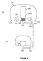
- Fig.8 and Fig.9 are a side view and a sectional view of a fuel tank 100 disclosed in Patent Reference 1.
- the fuel tank 100 is arranged on a pair of left and right tank rails (upper pipes) 101 and an inner bottom face 102 of the fuel tank disposed on inner sides of the pair of left and right tank rails constitutes an inclined face inclined to a rear lower side along an inclination of the tank rail 101.
- an outer side of the tank rail 101 of the fuel tank 101 is formed with an overhang portion 103
- a rearmost portion of the fuel tank 100 is formed with a horizontal face 104 disposed on an upper side of the tank rail 101 and the horizontal face constitutes the lowest portion of the fuel tank 100.
- a fuel pump 105 is arranged at an inner bottom face 102a constituting the inclined face of the fuel tank 100, and a lower side of the fuel pump 105 is formed with a projected portion 106 projected from the inner bottom face 102a of the fuel tank 100 to expose to outside.
- the proj ectedportion 106 is separated from the fuel tank 100 and a bottom portion of the projected portion 106 is provided with a suck in portion 107 of the fuel pump.
- the horizontal face 104 constituting the rearmost portion of the fuel tank 100 is provided with a suck out portion 108 of fuel and the suck out portion is connected to the suck in portion 107 of the fuel pump by a tube 109.
- Patent Reference 1 JP-A-2002-293281
- the projected portion 106 exposed to outside of the fuel tank needs to form separately from the fuel tank. Further, the suck out portion 108 of fuel needs to provide at the lowest portion of the fuel tank, further, the suck out portion 108 and the suck in portion 107 of the fuel pump provided to the projected portion 106 need to be connect by the tube 109.
- Such a constitution poses a new problem that not only a number of parts of the fuel tank is increased but also the number of operating steps is increased, as a result, the productivity is lowered and therefore, the cost is increased.
- the invention has been carried out in view of such a point, and it is an object thereof to provide a fuel tank capable of efficiently supplying a remaining fuel to a side of an engine by a simple constitution without increasing a number of parts.
- a fuel tank of a motor cycle of the invention is arranged on a pair of left and right tank rails constituting a vehicle body frame of the motor cycle, wherein the pair of left and right tank rails are inclined to rear lower sides; a bottom portion of the fuel tank includes an inner bottom portion disposed at a region between the pair of left and right tank rails, and outer bottom portions disposed at regions on outer sides of the pair of left and right tank rails; the inner bottom portion includes a first inclined face formed along an inclination of the tank rail at a front portion of the fuel tank and includes a first horizontal face at a rear portion of the fuel tank; the first inclined face and the first horizontal face are formed continuously in a front and rear direction while interposing a second inclined face therebetween, an inclination angle of the second inclined face being larger than that of the first inclined face; a pair of left and right projected streak portions straddling the tank rails are formed at regions between the first horizontal face of the inner bottom portion and the outer bottom portions; and a fuel pump is arranged at the first horizontal face
- the bottom portion of the fuel tank is integrally formed.
- the pair of left and right tank rails are connected by a cross member at middle portions thereof and the second inclined face is formed at a vicinity of a rear side of the cross member.
- the outer bottom portion includes a second horizontal face disposed at a height substantially the same as a height of the first horizontal face of the inner bottom portion.
- a third horizontal face formed by connecting the first horizontal face of the inner bottom portion and the second horizontal face of the outer bottom portion to each other at a rearmost portion of the fuel tank, wherein the third horizontal face is disposed on an upper side of a rear portion of the tank rail.
- the first horizontal face constitutes a lowest portion of the fuel tank.
- the second inclined face is provided with a function of preventing a fuel in the fuel tank from flowing to a front side of the fuel tank when the motor cycle is decelerated.
- a motor cycle of the invention is a motor cycle mounted with the above-described fuel tank.
- a fuel tank of an embodiment of the invention in a straddle-riding type vehicle including a pair of left and right tank rails constituting a vehicle body frame and extended in a front and rear direction, an engine supported by the vehicle body frame, a fuel tank arranged on upper sides of the left and right tank rails to be able to store a fuel to be supplied to a side of the engine and supported by the tank rails, and a fuel pump which is installed in the fuel tank and in which while the fuel in the fuel tank is sucked, the fuel is made to be able to be supplied to the side of the engine, a pair of left and right projected streak portions bulged to upper sides, extended in a front and rear direction and respectively externally fitted to the respective tank rails from upper sides thereof at a bottom plate of the fuel tank, and a sucking portion of the fuel in the fuel pump is arranged between the left and right projected streak portions and at a vicinity of substantially a lowest portion of an upper face of the bottom plate.
- the fuel pump is supported by a portion of the bottom plate at the vicinity of substantially the lowest portion of the upper face of the bottom plate.
- a front portion of a middle portion of the bottom plate disposed between the left and right projected streak portions it is preferable to incline a front portion of a middle portion of the bottom plate disposed between the left and right projected streak portions to extend to a front upper side.
- the fuel tank of the motor cycle of the invention by arranging the fuel pump at the first horizontal face disposed on the rear lower side of the first inclined face provided at the front portion of the fuel tank, fuel is easy to store to a portion arranged with the fuel pump. Further, the front side of the first horizontal face is formed with the second inclined face having the inclination angle larger than that of the first inclined face and therefore, when the motor cycle is decelerated, fuel can be prevented from flowing to the front side of the fuel tank.
- the pair of left and right projected streak portions straddling the tank rails are formed between the outer bottom portions disposed on the outer sides of the pair of left and right tank rails and the first horizontal face and therefore, when the motor cycle is banked in a left and right direction in running, fuel stored on the first horizontal face can be prevented from flowing in a lateral direction.
- first inclined face, the second inclined face, the first horizontal face, and the outer bottom portions constituting the bottom portion of the fuel tank can be formed by integrally forming the bottom portion of the fuel tank and therefore, the fuel tank can be fabricated by a simple constitution without needing extra parts and without increasing a number of operating steps.
- the second horizontal faces having the height substantially the same as that of the first horizontal face are provided at the outer bottom portions disposed on the outer sides of the tank rails, and the third horizontal face connected with the first horizontal face and the second horizontal face is formed at the rearmost portion of the fuel tank and therefore, when the motor cycle is accelerated, the fuel flowing from the outer bottom portions to rear sides are merged at the third horizontal face disposed at the rearmost portion of the fuel tank and can be collected to the vicinity of the first horizontal face arranged with the fuel pump. Thereby, even when the remaining amount of the fuel in the fuel tank is reduced, the remaining fuel can efficiently be supplied to the side of the engine.
- the bottom portion of the fuel tank disposed between the pair of left and right projected streak portions forms a recess portion by utilizing a space between the pair of left and right tank rails and therefore, a volume of the fuel tank can be enlarged without increasing a total height or a total width of the fuel tank.
- the inventors have investigated on how a fuel can efficiently be supplied to a side of an engine by a simple constitution without increasing cost under a restriction in view of layout, and as a result, the inventors are provided with the following knowledge.
- the fuel tank of a motor cycle is mounted on a tank rail inclined to a rear lower side and therefore, also abottomportion of the fuel tank is inclined along an inclination of the tank rail, and a fuel at inside of the fuel tank necessarily gathers to a rear portion of the fuel tank.
- a rear portion of the fuel tank is provided with a seat of a rider and therefore, a height of the fuel tank is restrained to be low and therefore, it is difficult to install a fuel pump at the rear portion of the fuel tank at which a fuel gathers.
- the fuel at inside of the fuel tank can be prevented from flowing in the front and rear direction and in the left and right direction in running and the fuel can be made to stay as near to the fuel pump as possible, in the actual running, the fuel can efficiently be supplied to the side of the engine.
- means effective for preventing the fuel at inside of the fuel tank from flowing in the front and rear direction and in the left and right direction can be constituted by providing a change in a shape at a bottom portion of the fuel tank.
- Such a change in the shape of the bottom portion of the fuel tank may be carried out at a portion at which the portion is not restricted in view of layout, further, the bottom portion of the fuel tank can be worked by integrally forming the bottom portion and therefore, design and fabrication thereof can easily be carried out and the bottom portion can be realized without increasing cost.
- Fig.1 is a view schematically showing a constitution of a fuel tank 1 according to an embodiment.
- the fuel tank 1 is arranged on a pair of left and right tank rails 2 constituting a vehicle body frame of a motor cycle, and the pair of left and right tank rails 2 are inclined to a rear lower side.
- a bottom portion of the fuel tank 1 includes an inner bottom portion 3 disposed between the pair of left and right tank rails 2 and outer bottom portions 4 disposed on outer sides of the pair of left and right tank rails 2.
- the inner bottom portion 3 includes a first inclined face 5 at a front portion of the fuel tank 1 and includes a first horizontal face 6 at a rear portion of the fuel tank 1.
- the first inclined face 5 and the first horizontal face 6 are continuously formed in a front and rear direction by interposing a second inclined face 7 having an inclination angle larger than that of the first inclined face 5. Further, a pair of left and right projected streak portions 9 straddling the tank rails 2 are formed at regions between the first horizontal face 6 of the inner bottom portion and the outer bottom portions 4. Further, a fuel pump 8 is arranged at the first horizontal face 6 of the inner bottom portion.
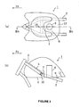
- Figs.2(a), (b) are a sectional view taken along a line IIa-IIa at the front portion of the fuel tank 1 shown in Fig.1 and a sectional view taken along a line IIb-IIb at the rear portion of the fuel tank 1.
- the inner bottom portion 3 disposed on inner sides of the pair of left and right tank rails 2 constitutes the first inclined face 5 and the outer bottom portions 4 disposed on outer sides of the tank rail 2 constitute overhangs disposed on a lower side of the first inclined face 5.
- the inner bottom portion 3 disposed on inner sides of the tank rail 2 constitutes the first horizontal face 6, and the first horizontal face 6 is connected to the outer bottom portions 4 disposed on outer sides of the tank rails 2 by the pair of projected streak portions 9 formed to straddle the tank rails 2. Further, the fuel pump 8 is arranged at the first horizontal face 6.
- first inclined face 5, the second inclined face 7, the first horizontal face 6, the outer bottom portions 4 and the pair of projected streak portion 9 respectively constitute a continuous face and therefore, can be formed by integrally forming by the same member.
- the pair of left and right tank rails 2 are connected by a cross member 10 at middle portions of the tank rails in order to reinforce a strength thereof, inthatcase, itisdifficultto form the second inclined face 7 on a front side of the cross member 10.
- the fuel tank 1 is installed from above the tank rails 2, when the second inclined face 7 is formed on the front side of the cross member 10, the bottom portion of the fuel tank 1 is brought into contact with the cross member 10 and the fuel tank 1 cannot be arranged at a predetermined position. Therefore, in order to widely ensure a region of the first horizontal face 6, it is preferable to form the second inclined face 7 as near to the rear side of the cross member 10 as possible.
- the outer bottom portions 4 disposed on the outer sides of the tank rails 2 may include second horizontal faces 11 disposed at a height substantially the same as that of the first horizontal face 6, further, the second horizontal faces 11 may be extended to the outer bottom portions 4 at the front portion of the fuel tank 1.
- Figs.3(a), (b) are a plane view of the fuel tank 1 and a sectional view of the fuel tank taken along a line IIIb-IIIb.
- the first horizontal face 6 of the inner bottom portion 3 and the second horizontal faces 11 of the outer bottom portion 4 are connected to each other to constitute a third horizontal face 12 at the connecting portion.
- the third horizontal face 12 can be formed by forming integrally with other faces constituting the bottom portion of the fuel tank 1.
- the third horizontal face 12 may be formed to be positioned slightly upward from the first horizontal face 6.
- the first horizontal face 6 constitutes the lowest portion of the fuel tank 1. That is, the fuel pump 8 is arranged at the lowest portion of the fuel tank 1.
- the fuel pump 8 by arranging the fuel pump 8 at the first horizontal face 6 disposed at a position lower than the first inclined face 5 provided at the front portion of the fuel tank 1 and provided at the rear portion of the fuel tank 1, fuel tends to be easily stored in the portion arranged with the fuel pump 8.
- the second inclined face 7 having the inclination angle larger than that of the first inclined face 5 is formed on the front side of the first horizontal face 6 and therefore, when the motor cycle is decelerated, fuel can be prevented from flowing to the front side of the fuel tank 1.
- the pair of left and right projected streak portions 9 straddling the tank rails 2 are formed between the outer bottom portions 4 disposed on the outer sides of the pair of left and right tank rails 2 and the first horizontal face 6 and therefore, fuel stored on the first horizontal face 6 can be prevented from flowing in a lateral direction.
- the first inclined face 5, the second inclined face 7, the first horizontal face 6 and the outer bottom portions 4 constituting the bottom portion of the fuel tank 1 according to the embodiment are integrally formed and therefore, the fuel tank can be fabricated by a simple constitution without needing extra parts and without increasing a number of operating steps.
- the bottom portion of the fuel tank 1 disposed between the pair of left and right projected streak portions 9 forms a recess portion utilizing a space between the pair of left and right tank rails and therefore, a volume thereof can be enlarged without increasing a total height or a total width of the fuel tank 1.
- the secondhorizontal faces 11 having the height substantially the same as that of the first horizontal face 6 are provided at the outer bottom portions 4 disposed on the outer sides of the tank rails 2, at the rearmost portion of the fuel tank 1, the third horizontal face 12 connected with the first horizontal face 6 and the second horizontal faces 11 is formed and therefore, when the motor cycle is accelerated, fuel flowing rearward from the outer bottom portions 4 can be collected to the vicinityof the first horizontal face 6 arranged with the fuel pump 8 by flowing to the third horizontal face 12 disposed at the rearmost portion of the fuel tank 1. Thereby, even when the remaining amount of fuel at inside of the fuel tank 1 is reduced, the remaining fuel can efficiently be supplied to the side of the engine.
- first horizontal face 6, the second horizontal face 11 and the third horizontal face 12 are not necessarily needed to be horizontal relative to the ground face but may be a plane disposed in the same face capable of being discriminated from the first inclined face 5 and the second inclined face 7.
- the projected streak portion 9 may be formed, for example, on upper sides of the tank rails 2 in order to ensure clearances between the projected streak portions 9 and the tank rails 2. Also in this case, the bottom portion of the fuel tank disposed between the pair of left and right projected streak portions 9 constitutes the recess portion.
- the arrow mark Fr designates the front side in a direction of advancing a vehicle 61.
- a vehicle body 62 of the vehicle 61 is provided with a vehicle body frame 63, a front fork 65 supported by a front portion of the vehicle body frame 63 for supporting a front wheel 64, a rear arm 66 pivotally supported by a rear portion of the vehicle body frame 63 for supporting a rear wheel, and a seat 67 which is supported by a rear portion of the vehicle body frame 63 and on which a rider can be seated in a straddle-riding style.
- the vehicle 61 is provided with a driving apparatus 70 for enabling to drive to run the rear wheel.
- the driving apparatus 70 is provided with an engine 71 constituting an internal combustion engine, and a power transmitting apparatus 72 cooperatively provided to the engine 71, and the engine 71 and the power transmitting apparatus 72 are supported by the vehicle body frame 63 integrally by a support piece 13.
- the vehicle 61 is provided with a throttle valve 14 cooperatively provided to a suction side of the engine 71, a fuel injection valve 16 for injecting a fuel 15 to an inner portion of the engine 71 to be able to supply thereto, and a chain wrapping type cooperatively moving means (not illustrated) for connecting the rear wheel to the power transmitting apparatus 72 to move cooperatively.
- the vehicle 61 is supported on the vehicle body frame 63 by a support piece 19 having a damping function.
- the fuel tank 1 stores the fuel 15 to be supplied to the engine 71 via the fuel injection valve 16.
- the fuel pump 8 of an electric type is contained in the fuel tank 1, supported by the fuel tank 1 by a fastening piece 23 and while the fuel pump 8 sucks the fuel 15 in the fuel tank 1, the fuel pump 8 pressurizes the fuel 15 to be able to be supplied to the fuel injection valve 16 via a fuel tube 21.
- An oil tank 26 stores a lubricating oil 25 to be supplied to the engine 71 as a dry sump system.
- the fuel 15 in the fuel tank 1 is supplied to an inner portion of the engine 71 via the fuel injection valve 16 by the fuel pump 8 to subject combustion. Further, by the oil pump cooperatively moved with the engine 71, the oil 25 in the oil tank 26 is supplied to respective lubricated portions of the driving apparatus 70 to lubricate to continue to drive the engine 71. Further, the vehicle 61 is made to be able to run by moving the rear wheel cooperatively with driving the engine 71 via the power transmitting apparatus 72.
- a head pipe 33 supports the front fork 65 at a front end portion of the vehicle body frame 63.
- a pair of left and right tank rails 2 are extended from an upper portion of the head pipe 33 to a rear lower side to support a rear portion of the driving apparatus 70 and support the fuel tank 1. Further, the cross member 10 couples middle portions of the tank rails 2.
- a down tube 36 is arranged on lower sides of the left and right tank rails 2 and extended from a lower portion of the head pipe 33 to a rear lower side to support a front portion of the driving apparatus 70.
- the head pipe 33 and a front end portion of the down tube 36 are solidly coupled to each other by a gusset 37 for reinforcement.
- a pair of left and right rear arm brackets 38 are integrally extended from front end portions of extending the respective tank rails 2 to lower sides to axially support the rear arm 66.
- Seat rails 39 are extended from end portions of extending the respective tank rails 2 to rear upper sides to support the seat 67.
- the fuel tank 1 is provided with a bottom plate 42 constituting a lower end portion thereof, and a tank main body 43 constituting a shape of an upside down bowl for covering the bottomplate 42 from an upper side thereof, and a closed space capable of storing the fuel 15 is formed by the bottom plate 42 and the tank main body 43.
- the bottom plate 42 of the fuel tank 1 is formed with the pair of left and right projected streak portions 9 bulged to upper sides, extended in a front and rear direction and externally fitted to the respective tank rails 2 from upper sides thereof.
- a front end portion of the middle portion 7 of the bottom plate 42 disposed between the left and right projected streak portions 9 is inclined to extend to a front upper side. Further, at least front portions of the respective projected streak portions 9 are inclined to extend to front upper sides along the respective tank rails 2.
- Rear ends of the respective projected streak portions 9 are separated from a rear end of an upper face of the bottom plate 42 to a front side, and a rear end portion of the upper face of the bottom plate 42 is made to constitute substantially a lowest portion 47 at the upper face of the bottom plate 42. Further, the respective outer portions 4 of the upper face of the bottom plate 42 respectively disposed on outer sides of the respective projected streak portions 9 and substantially the lowest portion 47 of the bottom plate 42 are disposed substantially on horizontal faces continuous to each other.
- the fuel pump 8 is arranged between the left and right projected streak portions 9, and a lower end portion of the fuel pump 8 is supported by a fastening piece 23 at a portion of the bottom plate 42 at a vicinity of substantially the lowest portion 47 of the upper face of the bottom plate 42. Further, the fuel pump 8 is provided with a sucking portion 51 formed at a lower end portion for sucking the fuel 15 and a filter 52 for filtering the fuel sucked to the sucking portion 51.
- the sucking portion 51 of the fuel pump 8 is arranged between the left and right projected streak portions 9, at a vicinity of substantially the lowest portion 47 in a horizontal direction, and at a vicinity of an upper side of an imaginary extended face of substantially the lowest portion 47 in an up an down direction.
- the sucking portion 51 is arranged substantially at a center portion 54 in a width direction of the vehicle 61.
- a delivery portion of the fuel pump 8 is communicated with a fuel injection valve 16 via the fuel tube 21.
- the bottom plate 42 of the fuel tank 1 is formed with the pair of left and right projected streak portions 9 bulged to upper sides, extended in the front and rear direction and respectively externally fitted to the respective tank rails 2 from the upper sides, and the sucking portion 51 of the fuel 15 of the fuel pump 8 is arranged between the left and right projected streak portions 9 and at a vicinity of substantially the lowest portion 47 of the upper face of the bottom plate 42.
- an interval of the left and right projected streak portions 9 constitutes a recess portion and therefore, constitutes a portion at which the fuel 15 is easily stored.
- the sucking portion 51 of the fuel pump 8 is arranged at a vicinity of substantially the lowest portion 47 of the upper face of the bottom plate 42 and therefore, even when a remaining amount of the fuel 15 in the fuel tank 1 is reduced, the fuel 15 is sufficiently supplied to the side of the engine 71 by the fuel pump 8.
- an interval between the left and right projected streak portions 9 is made to constitute the recess portion by utilizing a space between the left and right tank rails 2 and therefore, a volume of the fuel tank 1 is more increased than that of the background art.
- the sucking portion 51 of the fuel pump 8 is arranged between the left and right projected streak portions 9 formed in correspondence with the left and right tank rails 2 and is disposed substantially at the center portion 54 in the width direction of the vehicle 61 and therefore, even when the vehicle 61 is banked in a left and right direction in running, the fuel 15 is liable to remain at a surrounding of the sucking portion 51 of the fuel pump 8. Therefore, in such a running state of the vehicle 61, an amount of the fuel 15 supplied to the side of the engine 71 by the fuel pump 8 is restrained from being reduced.
- the fuel pump 8 is supported by a portion of the bottom plate 42 at a vicinity of substantially the lowest portion 47 of the upper face of the bottom plate 42. Therefore, in the fuel tank 1, the height of an upper end of the fuel pump 8 can be restrained to be low and therefore, even when the height of the fuel tank 1 is low, the fuel pump 8 is easily installed in the fuel tank 1.
- a front portion of the middle portion (inclined face) 7 of the bottom plate 42 disposed between the left and right projected streak portions 9 is inclined to extend to the front upper side and therefore, although when the vehicle 61 is decelerated in running, the fuel 15 in the fuel tank 1 is going to flow to the front side in the fuel tank 1 by an inertia force thereof, the flow is prevented by the middle portion 7 inclined to extend to the front upper side, and the fuel 15 is liable to remain at the surrounding of the sucking portion 51 of the fuel pump 8. Therefore, in such a running state of the vehicle 61, an amount of the fuel 15 supplied to the side of the engine 71 by the fuel pump 8 is restrained from being reduced.
- At least front portions of the respective projected streak portions 9 are inclined to extend respectively to front upper sides and therefore, although when the vehicle 61 is decelerated in running, the fuel 15 in the fuel tank 1 is going to flow to the front side in the fuel tank 1 by the inertia force, the flow is prevented by the respective projected streak portions 9 inclined to extend to the front upper sides, and the fuel 15 is liable to remain at the surrounding of the sucking portion 51 of the fuel pump 8. Therefore, even in such a state of running the vehicle 61, the amount of the fuel 15 supplied to the side of the engine 71 by the fuel pump 8 is restrained from being reduced.
- the rear ends of the respective projected members 9 are separated to the front sides from the rear end of the upper face of the bottom plate 42. Therefore, although when the vehicle 61 is accelerated in running, the fuel 15 in the fuel tank 1 is going to flow to the rear side in the fuel tank 1 by the inertia force, the fuel 15 flowing to the rear side in the outer side regions of the respective projected streak portions 9 smoothly and the fuel 15 flowing to the rear side between the left and right projected streak portions 9 are merged and the fuel 15 is liable to gather to the surrounding of the sucking portion 51 of the fuel pump 8. Therefore, even in such a state of running the vehicle 61, the amount of the fuel 15 supplied to the side of the engine 71 by the fuel pump 8 is restrained from being reduced.
- the outer side portions 4 of the upper face of the bottomplate 42 disposed on the outer sides of the respective projected members 9 and substantially the lowest portion 47 of the upper face of the bottom plate 42 are disposed substantially on the horizontal faces continuous to each other and therefore, even in the case of any of the states of running the vehicle 61, the fuel 15 in the fuel tank 1 totally flows to side of substantially the lowest portion 47 on the bottom plate 42 and is liable to gather to the surrounding of the sucking portion 51 of the fuel pump 8. Therefore, evenwhen the remaining amount of the fuel 15 in the fuel tank 1 is reduced, the fuel 15 can sufficiently be supplied to the side of the engine 71 by the fuel pump 8.
- the vehicle 61 may be an automatic three wheel vehicle or an automatic four wheel vehicle, the embodiment is more preferable to be applied to the motor cycle having a severe restriction in view of layout of the fuel tank.
- the fuel tank capable of supplying the remaining fuel efficiently to the side of the engine can be provided by a simple constitution.
Landscapes
- Engineering & Computer Science (AREA)
- Mechanical Engineering (AREA)
- Cooling, Air Intake And Gas Exhaust, And Fuel Tank Arrangements In Propulsion Units (AREA)
- Automatic Cycles, And Cycles In General (AREA)
Abstract
Description
- The present invention relates to a fuel tank of a motor cycle in which a fuel pump is installed at inside of the fuel tank, particularly relates to a fuel tank of a motor cycle for supplying a fuel remaining at inside of a fuel tank efficiently to a side of an engine.
- Generally, a fuel tank of a motor cycle is installed on a main frame (tank rail) connected to a head pipe, and an engine supported by the main frame is mounted on a lower side thereof. An exposing area of the fuel tank is large, and design performance thereof is emphasized while taking air resistance in running and a riding position of a rider into account. The engine is mounted on the lower side of the main frame supporting the fuel tank and the fuel tank is variously restricted in view of layout thereof such that a seat of the rider is arranged on a rear side of the fuel tank. Particularly, when there is adopted a pair of left and right frame structures for the main frame in order to promoted a rigidity of a vehicle body frame of the motor cycle, it is difficult to ensure a volume of the fuel pump by being hampered by the pair of left and right frames disposed on the lower side of the fuel tank.
- Meanwhile, although it is preferable to arrange the fuel pump at the lowest portion of the fuel tank to supply the remaining fuel efficiently to the side of the engine even when the remaining amount of the fuel at inside of the fuel tank becomes small, since the fuel tank is restricted in view of the above-described layout, design of the fuel tank for satisfying both of design feature and function feature thereof becomes difficult.
-
Patent Reference 1 describes a constitution of a fuel tank for efficiently supplying a remaining fuel to a side of an engine while ensuring design performance under such a restriction in view of layout. - Fig.8 and Fig.9 are a side view and a sectional view of a
fuel tank 100 disclosed inPatent Reference 1. As shown by Fig.8 and Fig.9, thefuel tank 100 is arranged on a pair of left and right tank rails (upper pipes) 101 and aninner bottom face 102 of the fuel tank disposed on inner sides of the pair of left and right tank rails constitutes an inclined face inclined to a rear lower side along an inclination of thetank rail 101. Further, an outer side of thetank rail 101 of thefuel tank 101 is formed with anoverhang portion 103, further, a rearmost portion of thefuel tank 100 is formed with ahorizontal face 104 disposed on an upper side of thetank rail 101 and the horizontal face constitutes the lowest portion of thefuel tank 100. - A
fuel pump 105 is arranged at aninner bottom face 102a constituting the inclined face of thefuel tank 100, and a lower side of thefuel pump 105 is formed with a projectedportion 106 projected from theinner bottom face 102a of thefuel tank 100 to expose to outside. Theproj ectedportion 106 is separated from thefuel tank 100 and a bottom portion of the projectedportion 106 is provided with a suck inportion 107 of the fuel pump. Further, thehorizontal face 104 constituting the rearmost portion of thefuel tank 100 is provided with a suck outportion 108 of fuel and the suck out portion is connected to the suck inportion 107 of the fuel pump by atube 109. - According to the above-described constitution, even when the
fuel pump 105 is not arranged at the lowest portion of thefuel tank 100, fuel can be sucked out always from the lowest portion of the fuel tank and the remaining fuel can efficiently be supplied to the side of the engine. Further, a degree of freedom for arranging the fuel tank is increased and therefore, the design performance of the fuel tank is not deteriorated. Further, the outer side of thetank rail 101 of thefuel tank 100 is formed with theoverhang portion 103 and therefore, the volume of thefuel tank 100 can be enlarged. - However, according to the
fuel tank 100 described inPatent Reference 1, the projectedportion 106 exposed to outside of the fuel tank needs to form separately from the fuel tank. Further, the suck outportion 108 of fuel needs to provide at the lowest portion of the fuel tank, further, the suck outportion 108 and the suck inportion 107 of the fuel pump provided to the projectedportion 106 need to be connect by thetube 109. Such a constitution poses a new problem that not only a number of parts of the fuel tank is increased but also the number of operating steps is increased, as a result, the productivity is lowered and therefore, the cost is increased. - The invention has been carried out in view of such a point, and it is an object thereof to provide a fuel tank capable of efficiently supplying a remaining fuel to a side of an engine by a simple constitution without increasing a number of parts. Means for Solving the Problems
- A fuel tank of a motor cycle of the invention is arranged on a pair of left and right tank rails constituting a vehicle body frame of the motor cycle, wherein the pair of left and right tank rails are inclined to rear lower sides; a bottom portion of the fuel tank includes an inner bottom portion disposed at a region between the pair of left and right tank rails, and outer bottom portions disposed at regions on outer sides of the pair of left and right tank rails; the inner bottom portion includes a first inclined face formed along an inclination of the tank rail at a front portion of the fuel tank and includes a first horizontal face at a rear portion of the fuel tank; the first inclined face and the first horizontal face are formed continuously in a front and rear direction while interposing a second inclined face therebetween, an inclination angle of the second inclined face being larger than that of the first inclined face; a pair of left and right projected streak portions straddling the tank rails are formed at regions between the first horizontal face of the inner bottom portion and the outer bottom portions; and a fuel pump is arranged at the first horizontal face of the inner bottom portion.
- In a preferable embodiment, the bottom portion of the fuel tank is integrally formed.
- In a preferable embodiment, the pair of left and right tank rails are connected by a cross member at middle portions thereof and the second inclined face is formed at a vicinity of a rear side of the cross member.
- In a preferable embodiment, the outer bottom portion includes a second horizontal face disposed at a height substantially the same as a height of the first horizontal face of the inner bottom portion.
- Also, it is preferable to further include a third horizontal face formed by connecting the first horizontal face of the inner bottom portion and the second horizontal face of the outer bottom portion to each other at a rearmost portion of the fuel tank, wherein the third horizontal face is disposed on an upper side of a rear portion of the tank rail.
- In a preferable embodiment, the first horizontal face constitutes a lowest portion of the fuel tank.
- Further, the second inclined face is provided with a function of preventing a fuel in the fuel tank from flowing to a front side of the fuel tank when the motor cycle is decelerated.
- A motor cycle of the invention is a motor cycle mounted with the above-described fuel tank.
- According to a fuel tank of an embodiment of the invention, in a straddle-riding type vehicle including a pair of left and right tank rails constituting a vehicle body frame and extended in a front and rear direction, an engine supported by the vehicle body frame, a fuel tank arranged on upper sides of the left and right tank rails to be able to store a fuel to be supplied to a side of the engine and supported by the tank rails, and a fuel pump which is installed in the fuel tank and in which while the fuel in the fuel tank is sucked, the fuel is made to be able to be supplied to the side of the engine, a pair of left and right projected streak portions bulged to upper sides, extended in a front and rear direction and respectively externally fitted to the respective tank rails from upper sides thereof at a bottom plate of the fuel tank, and a sucking portion of the fuel in the fuel pump is arranged between the left and right projected streak portions and at a vicinity of substantially a lowest portion of an upper face of the bottom plate.
- In an embodiment, it is preferable that the fuel pump is supported by a portion of the bottom plate at the vicinity of substantially the lowest portion of the upper face of the bottom plate.
- In an embodiment, it is preferable to incline a front portion of a middle portion of the bottom plate disposed between the left and right projected streak portions to extend to a front upper side.
- In an embodiment, it is preferable to incline at least front portions of the respective projected streak portions to incline respectively to front upper sides thereof.
- In an embodiment, it is preferable to separate rear ends of the respective projected streak portions to front sides from a rear end of the upper face of the bottom plate.
- In an embodiment, it is preferable to dispose outer portions of the upper face of the bottom plate disposed on outer sides of the respective projected streak portions and substantially a lowest portion of the upper face of the bottom plate substantially on horizontal faces continuous to each other.
- According to the fuel tank of the motor cycle of the invention, by arranging the fuel pump at the first horizontal face disposed on the rear lower side of the first inclined face provided at the front portion of the fuel tank, fuel is easy to store to a portion arranged with the fuel pump. Further, the front side of the first horizontal face is formed with the second inclined face having the inclination angle larger than that of the first inclined face and therefore, when the motor cycle is decelerated, fuel can be prevented from flowing to the front side of the fuel tank. Further, the pair of left and right projected streak portions straddling the tank rails are formed between the outer bottom portions disposed on the outer sides of the pair of left and right tank rails and the first horizontal face and therefore, when the motor cycle is banked in a left and right direction in running, fuel stored on the first horizontal face can be prevented from flowing in a lateral direction.
- By such an operation, even when a remaining amount of fuel in the fuel tank is reduced, the remaining fuel can be made to stay at a vicinity where the fuel tank is arranged and therefore, the remaining fuel can efficiently be supplied to the side of the engine.
- Further, the first inclined face, the second inclined face, the first horizontal face, and the outer bottom portions constituting the bottom portion of the fuel tank can be formed by integrally forming the bottom portion of the fuel tank and therefore, the fuel tank can be fabricated by a simple constitution without needing extra parts and without increasing a number of operating steps.
- Further, the second horizontal faces having the height substantially the same as that of the first horizontal face are provided at the outer bottom portions disposed on the outer sides of the tank rails, and the third horizontal face connected with the first horizontal face and the second horizontal face is formed at the rearmost portion of the fuel tank and therefore, when the motor cycle is accelerated, the fuel flowing from the outer bottom portions to rear sides are merged at the third horizontal face disposed at the rearmost portion of the fuel tank and can be collected to the vicinity of the first horizontal face arranged with the fuel pump. Thereby, even when the remaining amount of the fuel in the fuel tank is reduced, the remaining fuel can efficiently be supplied to the side of the engine.
- In addition thereto, the bottom portion of the fuel tank disposed between the pair of left and right projected streak portions forms a recess portion by utilizing a space between the pair of left and right tank rails and therefore, a volume of the fuel tank can be enlarged without increasing a total height or a total width of the fuel tank.
- Further, by constituting a lowest portion of the fuel tank by the first horizontal face, fuel is easily collected to the vicinity of the fuel pump and the remaining fuel can further efficiently be supplied to the side of the engine.
-
- Fig.1 is a view showing a constitution of a
fuel tank 1 according to the invention; - Fig.2 (a) is a sectional view taken along a line IIa-IIa of the
fuel tank 1 of Fig. 1, and Fig.2(b) is a sectional view tank along a line IIb-IIb thereof; - Fig.3 (a) is a plane view of the
fuel tank 1, and Fig.3 (b) is a sectional view taken along a line IIIb-IIIb of thefuel tank 1; - Fig.4 is a partial side view of a
vehicle 61 according to an embodiment of the invention; - Fig.5 is a side view of the
fuel tank 1 according to an embodiment of the invention; - Fig.6 is a plane view of the
fuel tank 1 according to the embodiment of the invention; - Fig.7 is a sectional view taken along a line VII-VII of the
fuel tank 1 of Fig.5; - Fig.8 is a view showing a constitution of a
fuel tank 100 of a background art; and - Fig. 9 (a) is a sectional view taken along a line IXa-IXa of the
fuel tank 100 of Fig. 8, and Fig. 9 (b) is a sectional view taken along a line IXb-IXb thereof. -
- 1
- fuel tank
- 2
- tank rail
- 3
- inner bottom portion
- 4
- outer bottom portion
- 5
- first inclined face
- 6
- first horizontal face
- 7
- second inclined face
- 8
- fuel pump
- 9
- projected streak portion
- 10
- cross member
- 11
- second horizontal face
- 12
- third horizontal face
- 15
- fuel
- 26
- oil tank
- 33
- head pipe
- 36
- down tube
- 37
- gusset
- 38
- rear arm bracket
- 51
- sucking portion
- 52
- filter
- 61
- vehicle
- 62
- vehicle body
- 63
- vehicle body frame
- 67
- seat
- 70
- driving apparatus
- 71
- engine
- 100
- fuel tank
- 101
- tank rail
- 102
- inner bottom face
- 103
- overhang portion
- 104
- horizontal face
- 105
- fuel pump
- 106
- projected portion
- 107
- suck in portion
- 108
- suck out portion
- 109
- tube
- The inventors have investigated on how a fuel can efficiently be supplied to a side of an engine by a simple constitution without increasing cost under a restriction in view of layout, and as a result, the inventors are provided with the following knowledge.
- Generally, the fuel tank of a motor cycle is mounted on a tank rail inclined to a rear lower side and therefore, also abottomportion of the fuel tank is inclined along an inclination of the tank rail, and a fuel at inside of the fuel tank necessarily gathers to a rear portion of the fuel tank. However, a rear portion of the fuel tank is provided with a seat of a rider and therefore, a height of the fuel tank is restrained to be low and therefore, it is difficult to install a fuel pump at the rear portion of the fuel tank at which a fuel gathers.
- However, actually, when a motor cycle is running, acceleration and deceleration are repeatedly carried out, further, the motor cycle moves up and down a hill and turns at a corner and therefore, at each occasion, the fuel at inside of the fuel tank always flows in a front and rear direction and in a left and right direction. That is, the fuel at inside of the fuel tank does not always stay at the rear portion of the fuel tank.
- Therefore, when the fuel at inside of the fuel tank can be prevented from flowing in the front and rear direction and in the left and right direction in running and the fuel can be made to stay as near to the fuel pump as possible, in the actual running, the fuel can efficiently be supplied to the side of the engine.
- Hence, the inventors have conceived that means effective for preventing the fuel at inside of the fuel tank from flowing in the front and rear direction and in the left and right direction can be constituted by providing a change in a shape at a bottom portion of the fuel tank. Such a change in the shape of the bottom portion of the fuel tank may be carried out at a portion at which the portion is not restricted in view of layout, further, the bottom portion of the fuel tank can be worked by integrally forming the bottom portion and therefore, design and fabrication thereof can easily be carried out and the bottom portion can be realized without increasing cost.
- An explanation will be given of a fuel tank according to an embodiment of the invention in reference to Fig.1 through Fig. 3 as follows. Incidentally, in the drawings, an arrow mark Fr designates a front side of a motor cycle.
- Fig.1 is a view schematically showing a constitution of a
fuel tank 1 according to an embodiment. Thefuel tank 1 is arranged on a pair of left andright tank rails 2 constituting a vehicle body frame of a motor cycle, and the pair of left andright tank rails 2 are inclined to a rear lower side. Further, a bottom portion of thefuel tank 1 includes aninner bottom portion 3 disposed between the pair of left andright tank rails 2 andouter bottom portions 4 disposed on outer sides of the pair of left and right tank rails 2. Further, theinner bottom portion 3 includes a firstinclined face 5 at a front portion of thefuel tank 1 and includes a firsthorizontal face 6 at a rear portion of thefuel tank 1. - The first
inclined face 5 and the firsthorizontal face 6 are continuously formed in a front and rear direction by interposing a secondinclined face 7 having an inclination angle larger than that of the firstinclined face 5. Further, a pair of left and right projectedstreak portions 9 straddling thetank rails 2 are formed at regions between the firsthorizontal face 6 of the inner bottom portion and theouter bottom portions 4. Further, afuel pump 8 is arranged at the firsthorizontal face 6 of the inner bottom portion. - Figs.2(a), (b) are a sectional view taken along a line IIa-IIa at the front portion of the
fuel tank 1 shown in Fig.1 and a sectional view taken along a line IIb-IIb at the rear portion of thefuel tank 1. - As shown by Fig.2(a), at the front portion of the
fuel tank 1, theinner bottom portion 3 disposed on inner sides of the pair of left and right tank rails 2 constitutes the firstinclined face 5 and theouter bottom portions 4 disposed on outer sides of thetank rail 2 constitute overhangs disposed on a lower side of the firstinclined face 5. - Further, as shown by Fig.2(b), at the rear portion of the
fuel tank 1, theinner bottom portion 3 disposed on inner sides of thetank rail 2 constitutes the firsthorizontal face 6, and the firsthorizontal face 6 is connected to theouter bottom portions 4 disposed on outer sides of thetank rails 2 by the pair of projectedstreak portions 9 formed to straddle the tank rails 2. Further, thefuel pump 8 is arranged at the firsthorizontal face 6. - Here, the first
inclined face 5, the secondinclined face 7, the firsthorizontal face 6, theouter bottom portions 4 and the pair of projectedstreak portion 9 respectively constitute a continuous face and therefore, can be formed by integrally forming by the same member. - Incidentally, there is a case in which the pair of left and
right tank rails 2 are connected by across member 10 at middle portions of the tank rails in order to reinforce a strength thereof, inthatcase, itisdifficultto form the secondinclined face 7 on a front side of thecross member 10. Because in the case in which thefuel tank 1 is installed from above thetank rails 2, when the secondinclined face 7 is formed on the front side of thecross member 10, the bottom portion of thefuel tank 1 is brought into contact with thecross member 10 and thefuel tank 1 cannot be arranged at a predetermined position. Therefore, in order to widely ensure a region of the firsthorizontal face 6, it is preferable to form the secondinclined face 7 as near to the rear side of thecross member 10 as possible. - Further, as shown by Fig.2(b), in the rear portion of the
fuel tank 1, theouter bottom portions 4 disposed on the outer sides of thetank rails 2 may include second horizontal faces 11 disposed at a height substantially the same as that of the firsthorizontal face 6, further, the second horizontal faces 11 may be extended to theouter bottom portions 4 at the front portion of thefuel tank 1. - Figs.3(a), (b) are a plane view of the
fuel tank 1 and a sectional view of the fuel tank taken along a line IIIb-IIIb. - As shown by Fig. 3 (a), at the rearmost portion of the bottom portion of the
fuel tank 1, the firsthorizontal face 6 of theinner bottom portion 3 and the second horizontal faces 11 of theouter bottom portion 4 are connected to each other to constitute a thirdhorizontal face 12 at the connecting portion. Naturally, the thirdhorizontal face 12 can be formed by forming integrally with other faces constituting the bottom portion of thefuel tank 1. - Further, as shown by Fig. 3 (b), the third
horizontal face 12 may be formed to be positioned slightly upward from the firsthorizontal face 6. In this case, the firsthorizontal face 6 constitutes the lowest portion of thefuel tank 1. That is, thefuel pump 8 is arranged at the lowest portion of thefuel tank 1. - According to the
fuel tank 1 of the embodiment, by arranging thefuel pump 8 at the firsthorizontal face 6 disposed at a position lower than the firstinclined face 5 provided at the front portion of thefuel tank 1 and provided at the rear portion of thefuel tank 1, fuel tends to be easily stored in the portion arranged with thefuel pump 8. - Further, the second
inclined face 7 having the inclination angle larger than that of the firstinclined face 5 is formed on the front side of the firsthorizontal face 6 and therefore, when the motor cycle is decelerated, fuel can be prevented from flowing to the front side of thefuel tank 1. - Further, the pair of left and right projected
streak portions 9 straddling thetank rails 2 are formed between theouter bottom portions 4 disposed on the outer sides of the pair of left andright tank rails 2 and the firsthorizontal face 6 and therefore, fuel stored on the firsthorizontal face 6 can be prevented from flowing in a lateral direction. - By such operation, even when a remaining amount of fuel at inside of the
fuel tank 1 is reduced, remaining fuel can be made to stay at a vicinity where thefuel pump 8 is arranged and therefore, the remaining fuel can efficiently be supplied to the side of the engine. - Incidentally, the first
inclined face 5, the secondinclined face 7, the firsthorizontal face 6 and theouter bottom portions 4 constituting the bottom portion of thefuel tank 1 according to the embodiment are integrally formed and therefore, the fuel tank can be fabricated by a simple constitution without needing extra parts and without increasing a number of operating steps. - Further, the bottom portion of the
fuel tank 1 disposed between the pair of left and right projectedstreak portions 9 forms a recess portion utilizing a space between the pair of left and right tank rails and therefore, a volume thereof can be enlarged without increasing a total height or a total width of thefuel tank 1. - In addition thereto, the secondhorizontal faces 11 having the height substantially the same as that of the first
horizontal face 6 are provided at theouter bottom portions 4 disposed on the outer sides of thetank rails 2, at the rearmost portion of thefuel tank 1, the thirdhorizontal face 12 connected with the firsthorizontal face 6 and the second horizontal faces 11 is formed and therefore, when the motor cycle is accelerated, fuel flowing rearward from theouter bottom portions 4 can be collected to the vicinityof the firsthorizontal face 6 arranged with thefuel pump 8 by flowing to the thirdhorizontal face 12 disposed at the rearmost portion of thefuel tank 1. Thereby, even when the remaining amount of fuel at inside of thefuel tank 1 is reduced, the remaining fuel can efficiently be supplied to the side of the engine. - Further, by placing the first
horizontal face 6 at the lowest portion of thefuel tank 1, fuel is easily collected to the vicinity of thefuel pump 8 and the remaining fuel can further efficiently be supplied to the side of the engine. - Further, in the embodiment, the first
horizontal face 6, the secondhorizontal face 11 and the thirdhorizontal face 12 are not necessarily needed to be horizontal relative to the ground face but may be a plane disposed in the same face capable of being discriminated from the firstinclined face 5 and the secondinclined face 7. - Further, although the pair of left and right projected
streak portions 9 are formed to straddle over thetank rail 2, the projectedstreak portion 9 may be formed, for example, on upper sides of thetank rails 2 in order to ensure clearances between the projectedstreak portions 9 and the tank rails 2. Also in this case, the bottom portion of the fuel tank disposed between the pair of left and right projectedstreak portions 9 constitutes the recess portion. - A detailed description will be given of the constitution of the fuel tank according to the embodiment in reference to Fig. 4 through Fig. 7 as follows. Insidentally, in the drawings, the arrow mark Fr designates the front side in a direction of advancing a
vehicle 61. - As shown by Fig.4, a
vehicle body 62 of thevehicle 61 is provided with avehicle body frame 63, afront fork 65 supported by a front portion of thevehicle body frame 63 for supporting afront wheel 64, arear arm 66 pivotally supported by a rear portion of thevehicle body frame 63 for supporting a rear wheel, and aseat 67 which is supported by a rear portion of thevehicle body frame 63 and on which a rider can be seated in a straddle-riding style. - Further, the
vehicle 61 is provided with a drivingapparatus 70 for enabling to drive to run the rear wheel. The drivingapparatus 70 is provided with anengine 71 constituting an internal combustion engine, and apower transmitting apparatus 72 cooperatively provided to theengine 71, and theengine 71 and thepower transmitting apparatus 72 are supported by thevehicle body frame 63 integrally by asupport piece 13. Further, thevehicle 61 is provided with athrottle valve 14 cooperatively provided to a suction side of theengine 71, afuel injection valve 16 for injecting afuel 15 to an inner portion of theengine 71 to be able to supply thereto, and a chain wrapping type cooperatively moving means (not illustrated) for connecting the rear wheel to thepower transmitting apparatus 72 to move cooperatively. - The
vehicle 61 is supported on thevehicle body frame 63 by asupport piece 19 having a damping function. Thefuel tank 1 stores thefuel 15 to be supplied to theengine 71 via thefuel injection valve 16. Further, thefuel pump 8 of an electric type is contained in thefuel tank 1, supported by thefuel tank 1 by afastening piece 23 and while thefuel pump 8 sucks thefuel 15 in thefuel tank 1, thefuel pump 8 pressurizes thefuel 15 to be able to be supplied to thefuel injection valve 16 via afuel tube 21. Anoil tank 26 stores a lubricatingoil 25 to be supplied to theengine 71 as a dry sump system. - When the
engine 71 of the drivingapparatus 70 is driven, thefuel 15 in thefuel tank 1 is supplied to an inner portion of theengine 71 via thefuel injection valve 16 by thefuel pump 8 to subject combustion. Further, by the oil pump cooperatively moved with theengine 71, theoil 25 in theoil tank 26 is supplied to respective lubricated portions of the drivingapparatus 70 to lubricate to continue to drive theengine 71. Further, thevehicle 61 is made to be able to run by moving the rear wheel cooperatively with driving theengine 71 via thepower transmitting apparatus 72. - A further detailed explanation will be given of the
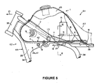
vehicle body frame 63 in reference to Fig.5. Ahead pipe 33 supports thefront fork 65 at a front end portion of thevehicle body frame 63. A pair of left andright tank rails 2 are extended from an upper portion of thehead pipe 33 to a rear lower side to support a rear portion of the drivingapparatus 70 and support thefuel tank 1. Further, thecross member 10 couples middle portions of the tank rails 2. - Further, a
down tube 36 is arranged on lower sides of the left andright tank rails 2 and extended from a lower portion of thehead pipe 33 to a rear lower side to support a front portion of the drivingapparatus 70. Thehead pipe 33 and a front end portion of thedown tube 36 are solidly coupled to each other by agusset 37 for reinforcement. Further, a pair of left and rightrear arm brackets 38 are integrally extended from front end portions of extending therespective tank rails 2 to lower sides to axially support therear arm 66. Seat rails 39 are extended from end portions of extending therespective tank rails 2 to rear upper sides to support theseat 67. - As shown by Fig. 6 and Fig. 7, the
fuel tank 1 is provided with abottom plate 42 constituting a lower end portion thereof, and a tankmain body 43 constituting a shape of an upside down bowl for covering the bottomplate 42 from an upper side thereof, and a closed space capable of storing thefuel 15 is formed by thebottom plate 42 and the tankmain body 43. - The
bottom plate 42 of thefuel tank 1 is formed with the pair of left and right projectedstreak portions 9 bulged to upper sides, extended in a front and rear direction and externally fitted to therespective tank rails 2 from upper sides thereof. A front end portion of themiddle portion 7 of thebottom plate 42 disposed between the left and right projectedstreak portions 9 is inclined to extend to a front upper side. Further, at least front portions of the respective projectedstreak portions 9 are inclined to extend to front upper sides along the respective tank rails 2. - Rear ends of the respective projected
streak portions 9 are separated from a rear end of an upper face of thebottom plate 42 to a front side, and a rear end portion of the upper face of thebottom plate 42 is made to constitute substantially a lowest portion 47 at the upper face of thebottom plate 42. Further, the respectiveouter portions 4 of the upper face of thebottom plate 42 respectively disposed on outer sides of the respective projectedstreak portions 9 and substantially the lowest portion 47 of thebottom plate 42 are disposed substantially on horizontal faces continuous to each other. - The
fuel pump 8 is arranged between the left and right projectedstreak portions 9, and a lower end portion of thefuel pump 8 is supported by afastening piece 23 at a portion of thebottom plate 42 at a vicinity of substantially the lowest portion 47 of the upper face of thebottom plate 42. Further, thefuel pump 8 is provided with a suckingportion 51 formed at a lower end portion for sucking thefuel 15 and afilter 52 for filtering the fuel sucked to the suckingportion 51. - Further, the sucking
portion 51 of thefuel pump 8 is arranged between the left and right projectedstreak portions 9, at a vicinity of substantially the lowest portion 47 in a horizontal direction, and at a vicinity of an upper side of an imaginary extended face of substantially the lowest portion 47 in an up an down direction. The suckingportion 51 is arranged substantially at acenter portion 54 in a width direction of thevehicle 61. Further, a delivery portion of thefuel pump 8 is communicated with afuel injection valve 16 via thefuel tube 21. - According to the above-described constitution, the
bottom plate 42 of thefuel tank 1 is formed with the pair of left and right projectedstreak portions 9 bulged to upper sides, extended in the front and rear direction and respectively externally fitted to therespective tank rails 2 from the upper sides, and the suckingportion 51 of thefuel 15 of thefuel pump 8 is arranged between the left and right projectedstreak portions 9 and at a vicinity of substantially the lowest portion 47 of the upper face of thebottom plate 42. - Here, an interval of the left and right projected
streak portions 9 constitutes a recess portion and therefore, constitutes a portion at which thefuel 15 is easily stored. Further, the suckingportion 51 of thefuel pump 8 is arranged at a vicinity of substantially the lowest portion 47 of the upper face of thebottom plate 42 and therefore, even when a remaining amount of thefuel 15 in thefuel tank 1 is reduced, thefuel 15 is sufficiently supplied to the side of theengine 71 by thefuel pump 8. - Further, an interval between the left and right projected
streak portions 9 is made to constitute the recess portion by utilizing a space between the left andright tank rails 2 and therefore, a volume of thefuel tank 1 is more increased than that of the background art. - Further, the sucking
portion 51 of thefuel pump 8 is arranged between the left and right projectedstreak portions 9 formed in correspondence with the left andright tank rails 2 and is disposed substantially at thecenter portion 54 in the width direction of thevehicle 61 and therefore, even when thevehicle 61 is banked in a left and right direction in running, thefuel 15 is liable to remain at a surrounding of the suckingportion 51 of thefuel pump 8. Therefore, in such a running state of thevehicle 61, an amount of thefuel 15 supplied to the side of theengine 71 by thefuel pump 8 is restrained from being reduced. - The
fuel pump 8 is supported by a portion of thebottom plate 42 at a vicinity of substantially the lowest portion 47 of the upper face of thebottom plate 42. Therefore, in thefuel tank 1, the height of an upper end of thefuel pump 8 can be restrained to be low and therefore, even when the height of thefuel tank 1 is low, thefuel pump 8 is easily installed in thefuel tank 1. - Further, a front portion of the middle portion (inclined face) 7 of the
bottom plate 42 disposed between the left and right projectedstreak portions 9 is inclined to extend to the front upper side and therefore, although when thevehicle 61 is decelerated in running, thefuel 15 in thefuel tank 1 is going to flow to the front side in thefuel tank 1 by an inertia force thereof, the flow is prevented by themiddle portion 7 inclined to extend to the front upper side, and thefuel 15 is liable to remain at the surrounding of the suckingportion 51 of thefuel pump 8. Therefore, in such a running state of thevehicle 61, an amount of thefuel 15 supplied to the side of theengine 71 by thefuel pump 8 is restrained from being reduced. - Further, at least front portions of the respective projected
streak portions 9 are inclined to extend respectively to front upper sides and therefore, although when thevehicle 61 is decelerated in running, thefuel 15 in thefuel tank 1 is going to flow to the front side in thefuel tank 1 by the inertia force, the flow is prevented by the respective projectedstreak portions 9 inclined to extend to the front upper sides, and thefuel 15 is liable to remain at the surrounding of the suckingportion 51 of thefuel pump 8. Therefore, even in such a state of running thevehicle 61, the amount of thefuel 15 supplied to the side of theengine 71 by thefuel pump 8 is restrained from being reduced. - The rear ends of the respective projected
members 9 are separated to the front sides from the rear end of the upper face of thebottom plate 42. Therefore, although when thevehicle 61 is accelerated in running, thefuel 15 in thefuel tank 1 is going to flow to the rear side in thefuel tank 1 by the inertia force, thefuel 15 flowing to the rear side in the outer side regions of the respective projectedstreak portions 9 smoothly and thefuel 15 flowing to the rear side between the left and right projectedstreak portions 9 are merged and thefuel 15 is liable to gather to the surrounding of the suckingportion 51 of thefuel pump 8. Therefore, even in such a state of running thevehicle 61, the amount of thefuel 15 supplied to the side of theengine 71 by thefuel pump 8 is restrained from being reduced. - Further, the
outer side portions 4 of the upper face of thebottomplate 42 disposed on the outer sides of the respective projectedmembers 9 and substantially the lowest portion 47 of the upper face of thebottom plate 42 are disposed substantially on the horizontal faces continuous to each other and therefore, even in the case of any of the states of running thevehicle 61, thefuel 15 in thefuel tank 1 totally flows to side of substantially the lowest portion 47 on thebottom plate 42 and is liable to gather to the surrounding of the suckingportion 51 of thefuel pump 8. Therefore, evenwhen the remaining amount of thefuel 15 in thefuel tank 1 is reduced, thefuel 15 can sufficiently be supplied to the side of theengine 71 by thefuel pump 8. - Although an explanation has been given of the invention by the preferable embodiment as described above, such a description is not an item of limitation but naturally can be modified variously. Further, in the above-described embodiment, although the
vehicle 61 may be an automatic three wheel vehicle or an automatic four wheel vehicle, the embodiment is more preferable to be applied to the motor cycle having a severe restriction in view of layout of the fuel tank. - According to the invention, the fuel tank capable of supplying the remaining fuel efficiently to the side of the engine can be provided by a simple constitution.
Claims (8)
- A fuel tank of a motor cycle which is arranged on a pair of left and right tank rails constituting a vehicle body frame of the motor cycle, characterized in that
the pair of left and right tank rails are inclined to rear lower sides;
a bottom portion of the fuel tank includes an inner bottom portion disposed at a region between the pair of left and right tank rails, and outer bottom portions disposed at regions on outer sides of the pair of left and right tank rails;
the inner bottom portion includes a first inclined face formed along an inclination of the tank rail at a front portion of the fuel tank and includes a first horizontal face at a rear portion of the fuel tank;
the first inclined face and the first horizontal face are formed continuously in a front and rear direction while interposing a second inclined face therebetween, aninclination angle of the second inclined face being larger than that of the first inclined face;
a pair of left and right projected streak portions straddling the tank rails are formed at regions between the first horizontal face of the inner bottom portion and the outer bottom portions; and
a fuel pump is arranged at the first horizontal face of the inner bottom portion. - The fuel tank of a motor cycle according to Claim 1,
characterized in that the bottom portion of the fuel tank is integrally formed. - The fuel tank of a motor cycle characterized in that the pair of left and right tank rails are connected by a cross member at middle portions thereof and the second inclined face is formed at a vicinity of a rear side of the cross member.
- The fuel tank of a motor cycle according to Claim 1,
characterized in that the outer bottom portion includes a second horizontal face disposed at a height substantially the same as a height of the first horizontal face of the inner bottom portion. - The fuel tank of a motor cycle according to Claim 4,
characterized by further comprising:a third horizontal face formed by connecting the first horizontal face of the inner bottom portion and the second horizontal face of the outer bottom portion to each other at a rearmost portion of the fuel tank;wherein the third horizontal face is disposed on an upper side of a rear portion of the tank rail. - The fuel tank of a motor cycle according to Claim 1,
characterized in that the first horizontal face constitutes a lowest portion of the fuel tank. - The fuel tank of a motor cycle according to Claim 1,
characterized in that the second inclined face is provided with a function of preventing a fuel in the fuel tank from flowing to a front side of the fuel tank when the motor cycle is decelerated. - A motor cycle mounted with the fuel tank according to any one of Claim 1 to 7.
Applications Claiming Priority (2)
| Application Number | Priority Date | Filing Date | Title |
|---|---|---|---|
| JP2003288279 | 2003-08-06 | ||
| PCT/JP2004/011183 WO2005014382A1 (en) | 2003-08-06 | 2004-08-04 | Fuel tank of motorcycle and motorcycle |
Publications (2)
| Publication Number | Publication Date |
|---|---|
| EP1655215A1 true EP1655215A1 (en) | 2006-05-10 |
| EP1655215B1 EP1655215B1 (en) | 2012-01-11 |
Family
ID=34131507
Family Applications (1)
| Application Number | Title | Priority Date | Filing Date |
|---|---|---|---|
| EP04771218A Expired - Lifetime EP1655215B1 (en) | 2003-08-06 | 2004-08-04 | Motorcycle |
Country Status (7)
| Country | Link |
|---|---|
| EP (1) | EP1655215B1 (en) |
| JP (1) | JP4031501B2 (en) |
| CN (1) | CN100427352C (en) |
| AT (1) | ATE540861T1 (en) |
| BR (1) | BRPI0406524B1 (en) |
| ES (1) | ES2378313T3 (en) |
| WO (1) | WO2005014382A1 (en) |
Cited By (1)
| Publication number | Priority date | Publication date | Assignee | Title |
|---|---|---|---|---|
| US11084548B2 (en) | 2017-09-29 | 2021-08-10 | Honda Motor Co., Ltd. | Fuel tank, method of manufacturing fuel tank, and saddle riding vehicle |
Families Citing this family (3)
| Publication number | Priority date | Publication date | Assignee | Title |
|---|---|---|---|---|
| JP5030485B2 (en) * | 2006-06-26 | 2012-09-19 | ヤマハ発動機株式会社 | Saddle riding vehicle |
| JP5620662B2 (en) * | 2009-09-15 | 2014-11-05 | 本田技研工業株式会社 | Motorcycle |
| JP6159604B2 (en) * | 2013-07-10 | 2017-07-05 | 本田技研工業株式会社 | Motorcycle body frame |
Family Cites Families (9)
| Publication number | Priority date | Publication date | Assignee | Title |
|---|---|---|---|---|
| JPS5625072A (en) * | 1979-08-04 | 1981-03-10 | Yamaha Motor Co Ltd | Fuel tank for autobicycle |
| JPS5940947A (en) | 1982-09-01 | 1984-03-06 | Honda Motor Co Ltd | Air cleaner case for motorcycles |
| JP2819290B2 (en) | 1988-07-15 | 1998-10-30 | ヤマハ発動機株式会社 | Motorcycle fuel tank device |
| JP3397973B2 (en) | 1996-05-31 | 2003-04-21 | ヤマハ発動機株式会社 | Motorcycle fuel tank structure |
| JP4108192B2 (en) | 1998-08-26 | 2008-06-25 | 本田技研工業株式会社 | Motorcycle fuel tank |
| JP2002254870A (en) * | 2001-03-02 | 2002-09-11 | Maruwa Kk | Bag-shaped sheet for filing |
| JP4518688B2 (en) * | 2001-03-09 | 2010-08-04 | ヤマハ発動機株式会社 | Saddle-type vehicle fuel tank system |
| JP3873646B2 (en) * | 2001-03-30 | 2007-01-24 | スズキ株式会社 | Motorcycle fuel supply system |
| CN1230343C (en) * | 2001-12-13 | 2005-12-07 | 雅马哈发动机株式会社 | Light motorcycle type fuel system structure for vehicle |
-
2004
- 2004-08-04 BR BRPI0406524-7A patent/BRPI0406524B1/en not_active IP Right Cessation
- 2004-08-04 JP JP2005512943A patent/JP4031501B2/en not_active Expired - Lifetime
- 2004-08-04 AT AT04771218T patent/ATE540861T1/en active
- 2004-08-04 CN CNB2004800115847A patent/CN100427352C/en not_active Expired - Lifetime
- 2004-08-04 WO PCT/JP2004/011183 patent/WO2005014382A1/en not_active Ceased
- 2004-08-04 EP EP04771218A patent/EP1655215B1/en not_active Expired - Lifetime
- 2004-08-04 ES ES04771218T patent/ES2378313T3/en not_active Expired - Lifetime
Non-Patent Citations (1)
| Title |
|---|
| See references of WO2005014382A1 * |
Cited By (1)
| Publication number | Priority date | Publication date | Assignee | Title |
|---|---|---|---|---|
| US11084548B2 (en) | 2017-09-29 | 2021-08-10 | Honda Motor Co., Ltd. | Fuel tank, method of manufacturing fuel tank, and saddle riding vehicle |
Also Published As
| Publication number | Publication date |
|---|---|
| ATE540861T1 (en) | 2012-01-15 |
| EP1655215B1 (en) | 2012-01-11 |
| JPWO2005014382A1 (en) | 2006-09-28 |
| BRPI0406524A (en) | 2005-12-13 |
| WO2005014382A1 (en) | 2005-02-17 |
| BRPI0406524B1 (en) | 2015-07-07 |
| ES2378313T3 (en) | 2012-04-11 |
| CN100427352C (en) | 2008-10-22 |
| JP4031501B2 (en) | 2008-01-09 |
| CN1780755A (en) | 2006-05-31 |
Similar Documents
| Publication | Publication Date | Title |
|---|---|---|
| EP1561941B1 (en) | A fuel injection system for a saddle ride type four-wheel vehicle | |
| EP2517953A1 (en) | Two-wheeled motor vehicle with supercharger | |
| BR102012031833A2 (en) | saddle mount type vehicle | |
| JP4354662B2 (en) | Fuel device | |
| CN101172503A (en) | motorcycle | |
| EP1655215B1 (en) | Motorcycle | |
| JP2013136342A (en) | Straddle-type vehicle | |
| JP3677005B2 (en) | Fuel tank for vehicles | |
| JP3873646B2 (en) | Motorcycle fuel supply system | |
| EP1783040A1 (en) | Straddle-type vehicle | |
| CN101468697B (en) | Straddle type vehicle | |
| JP4211778B2 (en) | Motorcycle fuel supply system | |
| JP5620662B2 (en) | Motorcycle | |
| EP1584548B1 (en) | Method of manufacturing motorcycle and tank-in frame of motorcycle | |
| JP5572050B2 (en) | Fuel tank for motorcycle | |
| JP2016049967A (en) | Intake device of internal combustion engine for small-sized vehicle | |
| EP4080020B1 (en) | Internal combustion engine and straddled vehicle | |
| JP7478904B2 (en) | Saddle type vehicle | |
| US20260062088A1 (en) | Frame structure | |
| US20030116115A1 (en) | Lubrication unit for internal combustion engine | |
| KR20200001963A (en) | Combine | |
| JP3823975B2 (en) | Motorcycle fuel supply system | |
| JP2018178743A (en) | Internal combustion engine | |
| JP3168136U (en) | Scooter-type vehicle intake system | |
| WO2023053415A1 (en) | Power unit |
Legal Events
| Date | Code | Title | Description |
|---|---|---|---|
| PUAI | Public reference made under article 153(3) epc to a published international application that has entered the european phase |
Free format text: ORIGINAL CODE: 0009012 |
|
| 17P | Request for examination filed |
Effective date: 20060223 |
|
| AK | Designated contracting states |
Kind code of ref document: A1 Designated state(s): AT BE BG CH CY CZ DE DK EE ES FI FR GB GR HU IE IT LI LU MC NL PL PT RO SE SI SK TR |
|
| DAX | Request for extension of the european patent (deleted) | ||
| R17P | Request for examination filed (corrected) |
Effective date: 20060223 |
|
| 17Q | First examination report despatched |
Effective date: 20091120 |
|
| GRAP | Despatch of communication of intention to grant a patent |
Free format text: ORIGINAL CODE: EPIDOSNIGR1 |
|
| RTI1 | Title (correction) |
Free format text: MOTORCYCLE |
|
| GRAS | Grant fee paid |
Free format text: ORIGINAL CODE: EPIDOSNIGR3 |
|
| GRAA | (expected) grant |
Free format text: ORIGINAL CODE: 0009210 |
|
| AK | Designated contracting states |
Kind code of ref document: B1 Designated state(s): AT BE BG CH CY CZ DE DK EE ES FI FR GB GR HU IE IT LI LU MC NL PL PT RO SE SI SK TR |
|
| REG | Reference to a national code |
Ref country code: GB Ref legal event code: FG4D |
|
| REG | Reference to a national code |
Ref country code: CH Ref legal event code: EP |
|
| REG | Reference to a national code |
Ref country code: AT Ref legal event code: REF Ref document number: 540861 Country of ref document: AT Kind code of ref document: T Effective date: 20120115 |
|
| REG | Reference to a national code |
Ref country code: IE Ref legal event code: FG4D |
|
| REG | Reference to a national code |
Ref country code: DE Ref legal event code: R096 Ref document number: 602004036108 Country of ref document: DE Effective date: 20120308 |
|
| REG | Reference to a national code |
Ref country code: ES Ref legal event code: FG2A Ref document number: 2378313 Country of ref document: ES Kind code of ref document: T3 Effective date: 20120411 |
|
| RAP2 | Party data changed (patent owner data changed or rights of a patent transferred) |
Owner name: YAMAHA HATSUDOKI KABUSHIKI KAISHA |
|
| REG | Reference to a national code |
Ref country code: NL Ref legal event code: VDEP Effective date: 20120111 |
|
| PG25 | Lapsed in a contracting state [announced via postgrant information from national office to epo] |
Ref country code: SI Free format text: LAPSE BECAUSE OF FAILURE TO SUBMIT A TRANSLATION OF THE DESCRIPTION OR TO PAY THE FEE WITHIN THE PRESCRIBED TIME-LIMIT Effective date: 20120111 |
|
| REG | Reference to a national code |
Ref country code: DE Ref legal event code: R082 Ref document number: 602004036108 Country of ref document: DE Representative=s name: GRUENECKER, KINKELDEY, STOCKMAIR & SCHWANHAEUS, DE |
|
| PG25 | Lapsed in a contracting state [announced via postgrant information from national office to epo] |
Ref country code: NL Free format text: LAPSE BECAUSE OF FAILURE TO SUBMIT A TRANSLATION OF THE DESCRIPTION OR TO PAY THE FEE WITHIN THE PRESCRIBED TIME-LIMIT Effective date: 20120111 Ref country code: BE Free format text: LAPSE BECAUSE OF FAILURE TO SUBMIT A TRANSLATION OF THE DESCRIPTION OR TO PAY THE FEE WITHIN THE PRESCRIBED TIME-LIMIT Effective date: 20120111 Ref country code: BG Free format text: LAPSE BECAUSE OF FAILURE TO SUBMIT A TRANSLATION OF THE DESCRIPTION OR TO PAY THE FEE WITHIN THE PRESCRIBED TIME-LIMIT Effective date: 20120411 |
|
| PG25 | Lapsed in a contracting state [announced via postgrant information from national office to epo] |
Ref country code: GR Free format text: LAPSE BECAUSE OF FAILURE TO SUBMIT A TRANSLATION OF THE DESCRIPTION OR TO PAY THE FEE WITHIN THE PRESCRIBED TIME-LIMIT Effective date: 20120412 Ref country code: FI Free format text: LAPSE BECAUSE OF FAILURE TO SUBMIT A TRANSLATION OF THE DESCRIPTION OR TO PAY THE FEE WITHIN THE PRESCRIBED TIME-LIMIT Effective date: 20120111 Ref country code: PL Free format text: LAPSE BECAUSE OF FAILURE TO SUBMIT A TRANSLATION OF THE DESCRIPTION OR TO PAY THE FEE WITHIN THE PRESCRIBED TIME-LIMIT Effective date: 20120111 Ref country code: PT Free format text: LAPSE BECAUSE OF FAILURE TO SUBMIT A TRANSLATION OF THE DESCRIPTION OR TO PAY THE FEE WITHIN THE PRESCRIBED TIME-LIMIT Effective date: 20120511 |
|
| REG | Reference to a national code |
Ref country code: DE Ref legal event code: R081 Ref document number: 602004036108 Country of ref document: DE Owner name: YAMAHA HATSUDOKI KABUSHIKI KAISHA, JP Free format text: FORMER OWNER: YAMAHA MOTOR CO., LTD., IWATA, JP Effective date: 20120118 Ref country code: DE Ref legal event code: R082 Ref document number: 602004036108 Country of ref document: DE Representative=s name: GRUENECKER, KINKELDEY, STOCKMAIR & SCHWANHAEUS, DE Effective date: 20120723 Ref country code: DE Ref legal event code: R081 Ref document number: 602004036108 Country of ref document: DE Owner name: YAMAHA HATSUDOKI KABUSHIKI KAISHA, JP Free format text: FORMER OWNER: YAMAHA MOTOR CO., LTD., IWATA, JP Effective date: 20120723 Ref country code: DE Ref legal event code: R081 Ref document number: 602004036108 Country of ref document: DE Owner name: YAMAHA HATSUDOKI KABUSHIKI KAISHA, IWATA, JP Free format text: FORMER OWNER: YAMAHA MOTOR CO., LTD., IWATA, SHIZUOKA, JP Effective date: 20120723 Ref country code: DE Ref legal event code: R081 Ref document number: 602004036108 Country of ref document: DE Owner name: YAMAHA HATSUDOKI KABUSHIKI KAISHA, IWATA, JP Free format text: FORMER OWNER: YAMAHA MOTOR CO., LTD., IWATA, SHIZUOKA, JP Effective date: 20120118 Ref country code: DE Ref legal event code: R082 Ref document number: 602004036108 Country of ref document: DE Representative=s name: GRUENECKER PATENT- UND RECHTSANWAELTE PARTG MB, DE Effective date: 20120723 |
|
| REG | Reference to a national code |
Ref country code: AT Ref legal event code: MK05 Ref document number: 540861 Country of ref document: AT Kind code of ref document: T Effective date: 20120111 |
|
| PG25 | Lapsed in a contracting state [announced via postgrant information from national office to epo] |
Ref country code: CY Free format text: LAPSE BECAUSE OF FAILURE TO SUBMIT A TRANSLATION OF THE DESCRIPTION OR TO PAY THE FEE WITHIN THE PRESCRIBED TIME-LIMIT Effective date: 20120111 |
|
| PG25 | Lapsed in a contracting state [announced via postgrant information from national office to epo] |
Ref country code: CZ Free format text: LAPSE BECAUSE OF FAILURE TO SUBMIT A TRANSLATION OF THE DESCRIPTION OR TO PAY THE FEE WITHIN THE PRESCRIBED TIME-LIMIT Effective date: 20120111 Ref country code: RO Free format text: LAPSE BECAUSE OF FAILURE TO SUBMIT A TRANSLATION OF THE DESCRIPTION OR TO PAY THE FEE WITHIN THE PRESCRIBED TIME-LIMIT Effective date: 20120111 Ref country code: SE Free format text: LAPSE BECAUSE OF FAILURE TO SUBMIT A TRANSLATION OF THE DESCRIPTION OR TO PAY THE FEE WITHIN THE PRESCRIBED TIME-LIMIT Effective date: 20120111 Ref country code: EE Free format text: LAPSE BECAUSE OF FAILURE TO SUBMIT A TRANSLATION OF THE DESCRIPTION OR TO PAY THE FEE WITHIN THE PRESCRIBED TIME-LIMIT Effective date: 20120111 Ref country code: DK Free format text: LAPSE BECAUSE OF FAILURE TO SUBMIT A TRANSLATION OF THE DESCRIPTION OR TO PAY THE FEE WITHIN THE PRESCRIBED TIME-LIMIT Effective date: 20120111 |
|
| PLBE | No opposition filed within time limit |
Free format text: ORIGINAL CODE: 0009261 |
|
| STAA | Information on the status of an ep patent application or granted ep patent |
Free format text: STATUS: NO OPPOSITION FILED WITHIN TIME LIMIT |
|
| PG25 | Lapsed in a contracting state [announced via postgrant information from national office to epo] |
Ref country code: SK Free format text: LAPSE BECAUSE OF FAILURE TO SUBMIT A TRANSLATION OF THE DESCRIPTION OR TO PAY THE FEE WITHIN THE PRESCRIBED TIME-LIMIT Effective date: 20120111 |
|
| 26N | No opposition filed |
Effective date: 20121012 |
|
| PG25 | Lapsed in a contracting state [announced via postgrant information from national office to epo] |
Ref country code: AT Free format text: LAPSE BECAUSE OF FAILURE TO SUBMIT A TRANSLATION OF THE DESCRIPTION OR TO PAY THE FEE WITHIN THE PRESCRIBED TIME-LIMIT Effective date: 20120111 |
|
| REG | Reference to a national code |
Ref country code: DE Ref legal event code: R097 Ref document number: 602004036108 Country of ref document: DE Effective date: 20121012 |
|
| REG | Reference to a national code |
Ref country code: CH Ref legal event code: PL |
|
| PG25 | Lapsed in a contracting state [announced via postgrant information from national office to epo] |
Ref country code: MC Free format text: LAPSE BECAUSE OF NON-PAYMENT OF DUE FEES Effective date: 20120831 |
|
| PG25 | Lapsed in a contracting state [announced via postgrant information from national office to epo] |
Ref country code: LI Free format text: LAPSE BECAUSE OF NON-PAYMENT OF DUE FEES Effective date: 20120831 Ref country code: CH Free format text: LAPSE BECAUSE OF NON-PAYMENT OF DUE FEES Effective date: 20120831 |
|
| REG | Reference to a national code |
Ref country code: IE Ref legal event code: MM4A |
|
| PG25 | Lapsed in a contracting state [announced via postgrant information from national office to epo] |
Ref country code: IE Free format text: LAPSE BECAUSE OF NON-PAYMENT OF DUE FEES Effective date: 20120804 |
|
| PG25 | Lapsed in a contracting state [announced via postgrant information from national office to epo] |
Ref country code: TR Free format text: LAPSE BECAUSE OF FAILURE TO SUBMIT A TRANSLATION OF THE DESCRIPTION OR TO PAY THE FEE WITHIN THE PRESCRIBED TIME-LIMIT Effective date: 20120111 |
|
| PG25 | Lapsed in a contracting state [announced via postgrant information from national office to epo] |
Ref country code: LU Free format text: LAPSE BECAUSE OF NON-PAYMENT OF DUE FEES Effective date: 20120804 |
|
| PG25 | Lapsed in a contracting state [announced via postgrant information from national office to epo] |
Ref country code: HU Free format text: LAPSE BECAUSE OF FAILURE TO SUBMIT A TRANSLATION OF THE DESCRIPTION OR TO PAY THE FEE WITHIN THE PRESCRIBED TIME-LIMIT Effective date: 20040804 |
|
| REG | Reference to a national code |
Ref country code: FR Ref legal event code: PLFP Year of fee payment: 13 |
|
| REG | Reference to a national code |
Ref country code: FR Ref legal event code: PLFP Year of fee payment: 14 |
|
| REG | Reference to a national code |
Ref country code: FR Ref legal event code: PLFP Year of fee payment: 15 |
|
| P01 | Opt-out of the competence of the unified patent court (upc) registered |
Effective date: 20230527 |
|
| PGFP | Annual fee paid to national office [announced via postgrant information from national office to epo] |
Ref country code: IT Payment date: 20230825 Year of fee payment: 20 Ref country code: GB Payment date: 20230824 Year of fee payment: 20 |
|
| PGFP | Annual fee paid to national office [announced via postgrant information from national office to epo] |
Ref country code: FR Payment date: 20230822 Year of fee payment: 20 Ref country code: DE Payment date: 20230821 Year of fee payment: 20 |
|
| PGFP | Annual fee paid to national office [announced via postgrant information from national office to epo] |
Ref country code: ES Payment date: 20231027 Year of fee payment: 20 |
|
| REG | Reference to a national code |
Ref country code: DE Ref legal event code: R071 Ref document number: 602004036108 Country of ref document: DE |
|
| REG | Reference to a national code |
Ref country code: ES Ref legal event code: FD2A Effective date: 20240826 |
|
| REG | Reference to a national code |
Ref country code: GB Ref legal event code: PE20 Expiry date: 20240803 |
|
| PG25 | Lapsed in a contracting state [announced via postgrant information from national office to epo] |
Ref country code: GB Free format text: LAPSE BECAUSE OF EXPIRATION OF PROTECTION Effective date: 20240803 |
|
| PG25 | Lapsed in a contracting state [announced via postgrant information from national office to epo] |
Ref country code: ES Free format text: LAPSE BECAUSE OF EXPIRATION OF PROTECTION Effective date: 20240805 |
|
| PG25 | Lapsed in a contracting state [announced via postgrant information from national office to epo] |
Ref country code: GB Free format text: LAPSE BECAUSE OF EXPIRATION OF PROTECTION Effective date: 20240803 Ref country code: ES Free format text: LAPSE BECAUSE OF EXPIRATION OF PROTECTION Effective date: 20240805 |