EP1654989A2 - Ovaler Stift zum Fixieren eines unter Zuglast beanspruchten Implantates - Google Patents
Ovaler Stift zum Fixieren eines unter Zuglast beanspruchten Implantates Download PDFInfo
- Publication number
- EP1654989A2 EP1654989A2 EP05023522A EP05023522A EP1654989A2 EP 1654989 A2 EP1654989 A2 EP 1654989A2 EP 05023522 A EP05023522 A EP 05023522A EP 05023522 A EP05023522 A EP 05023522A EP 1654989 A2 EP1654989 A2 EP 1654989A2
- Authority
- EP
- European Patent Office
- Prior art keywords
- cross
- pin
- implant
- section
- tendon
- Prior art date
- Legal status (The legal status is an assumption and is not a legal conclusion. Google has not performed a legal analysis and makes no representation as to the accuracy of the status listed.)
- Granted
Links
Images
Classifications
-
- A—HUMAN NECESSITIES
- A61—MEDICAL OR VETERINARY SCIENCE; HYGIENE
- A61F—FILTERS IMPLANTABLE INTO BLOOD VESSELS; PROSTHESES; DEVICES PROVIDING PATENCY TO, OR PREVENTING COLLAPSING OF, TUBULAR STRUCTURES OF THE BODY, e.g. STENTS; ORTHOPAEDIC, NURSING OR CONTRACEPTIVE DEVICES; FOMENTATION; TREATMENT OR PROTECTION OF EYES OR EARS; BANDAGES, DRESSINGS OR ABSORBENT PADS; FIRST-AID KITS
- A61F2/00—Filters implantable into blood vessels; Prostheses, i.e. artificial substitutes or replacements for parts of the body; Appliances for connecting them with the body; Devices providing patency to, or preventing collapsing of, tubular structures of the body, e.g. stents
- A61F2/02—Prostheses implantable into the body
- A61F2/08—Muscles; Tendons; Ligaments
- A61F2/0811—Fixation devices for tendons or ligaments
-
- A—HUMAN NECESSITIES
- A61—MEDICAL OR VETERINARY SCIENCE; HYGIENE
- A61B—DIAGNOSIS; SURGERY; IDENTIFICATION
- A61B17/00—Surgical instruments, devices or methods
- A61B17/04—Surgical instruments, devices or methods for suturing wounds; Holders or packages for needles or suture materials
- A61B17/0401—Suture anchors, buttons or pledgets, i.e. means for attaching sutures to bone, cartilage or soft tissue; Instruments for applying or removing suture anchors
-
- A—HUMAN NECESSITIES
- A61—MEDICAL OR VETERINARY SCIENCE; HYGIENE
- A61B—DIAGNOSIS; SURGERY; IDENTIFICATION
- A61B17/00—Surgical instruments, devices or methods
- A61B17/064—Surgical staples, i.e. penetrating the tissue
- A61B17/0642—Surgical staples, i.e. penetrating the tissue for bones, e.g. for osteosynthesis or connecting tendon to bone
-
- A—HUMAN NECESSITIES
- A61—MEDICAL OR VETERINARY SCIENCE; HYGIENE
- A61B—DIAGNOSIS; SURGERY; IDENTIFICATION
- A61B17/00—Surgical instruments, devices or methods
- A61B2017/00004—(bio)absorbable, (bio)resorbable or resorptive
-
- A—HUMAN NECESSITIES
- A61—MEDICAL OR VETERINARY SCIENCE; HYGIENE
- A61B—DIAGNOSIS; SURGERY; IDENTIFICATION
- A61B17/00—Surgical instruments, devices or methods
- A61B17/04—Surgical instruments, devices or methods for suturing wounds; Holders or packages for needles or suture materials
- A61B17/0401—Suture anchors, buttons or pledgets, i.e. means for attaching sutures to bone, cartilage or soft tissue; Instruments for applying or removing suture anchors
- A61B2017/0403—Dowels
-
- A—HUMAN NECESSITIES
- A61—MEDICAL OR VETERINARY SCIENCE; HYGIENE
- A61B—DIAGNOSIS; SURGERY; IDENTIFICATION
- A61B17/00—Surgical instruments, devices or methods
- A61B17/064—Surgical staples, i.e. penetrating the tissue
- A61B2017/0647—Surgical staples, i.e. penetrating the tissue having one single leg, e.g. tacks
-
- A—HUMAN NECESSITIES
- A61—MEDICAL OR VETERINARY SCIENCE; HYGIENE
- A61F—FILTERS IMPLANTABLE INTO BLOOD VESSELS; PROSTHESES; DEVICES PROVIDING PATENCY TO, OR PREVENTING COLLAPSING OF, TUBULAR STRUCTURES OF THE BODY, e.g. STENTS; ORTHOPAEDIC, NURSING OR CONTRACEPTIVE DEVICES; FOMENTATION; TREATMENT OR PROTECTION OF EYES OR EARS; BANDAGES, DRESSINGS OR ABSORBENT PADS; FIRST-AID KITS
- A61F2/00—Filters implantable into blood vessels; Prostheses, i.e. artificial substitutes or replacements for parts of the body; Appliances for connecting them with the body; Devices providing patency to, or preventing collapsing of, tubular structures of the body, e.g. stents
- A61F2/02—Prostheses implantable into the body
- A61F2/08—Muscles; Tendons; Ligaments
- A61F2/0811—Fixation devices for tendons or ligaments
- A61F2002/0817—Structure of the anchor
- A61F2002/0823—Modular anchors comprising a plurality of separate parts
- A61F2002/0829—Modular anchors comprising a plurality of separate parts without deformation of anchor parts, e.g. fixation screws on bone surface, extending barbs, cams, butterflies, spring-loaded pins
-
- A—HUMAN NECESSITIES
- A61—MEDICAL OR VETERINARY SCIENCE; HYGIENE
- A61F—FILTERS IMPLANTABLE INTO BLOOD VESSELS; PROSTHESES; DEVICES PROVIDING PATENCY TO, OR PREVENTING COLLAPSING OF, TUBULAR STRUCTURES OF THE BODY, e.g. STENTS; ORTHOPAEDIC, NURSING OR CONTRACEPTIVE DEVICES; FOMENTATION; TREATMENT OR PROTECTION OF EYES OR EARS; BANDAGES, DRESSINGS OR ABSORBENT PADS; FIRST-AID KITS
- A61F2/00—Filters implantable into blood vessels; Prostheses, i.e. artificial substitutes or replacements for parts of the body; Appliances for connecting them with the body; Devices providing patency to, or preventing collapsing of, tubular structures of the body, e.g. stents
- A61F2/02—Prostheses implantable into the body
- A61F2/08—Muscles; Tendons; Ligaments
- A61F2/0811—Fixation devices for tendons or ligaments
- A61F2002/0847—Mode of fixation of anchor to tendon or ligament
- A61F2002/0852—Fixation of a loop or U-turn, e.g. eyelets, anchor having multiple holes
-
- A—HUMAN NECESSITIES
- A61—MEDICAL OR VETERINARY SCIENCE; HYGIENE
- A61F—FILTERS IMPLANTABLE INTO BLOOD VESSELS; PROSTHESES; DEVICES PROVIDING PATENCY TO, OR PREVENTING COLLAPSING OF, TUBULAR STRUCTURES OF THE BODY, e.g. STENTS; ORTHOPAEDIC, NURSING OR CONTRACEPTIVE DEVICES; FOMENTATION; TREATMENT OR PROTECTION OF EYES OR EARS; BANDAGES, DRESSINGS OR ABSORBENT PADS; FIRST-AID KITS
- A61F2/00—Filters implantable into blood vessels; Prostheses, i.e. artificial substitutes or replacements for parts of the body; Appliances for connecting them with the body; Devices providing patency to, or preventing collapsing of, tubular structures of the body, e.g. stents
- A61F2/02—Prostheses implantable into the body
- A61F2/08—Muscles; Tendons; Ligaments
- A61F2/0811—Fixation devices for tendons or ligaments
- A61F2002/0876—Position of anchor in respect to the bone
- A61F2002/0882—Anchor in or on top of a bone tunnel, i.e. a hole running through the entire bone
Definitions
- the invention relates to a pin for fixing a stressed under tensile load implant, in particular a tendon implant, with a rod-shaped body on the cross section on one side of the force exerted by the implant force is introduced and derivable on the opposite side in an anchoring point.
- Such pins serve to fix an implant inserted in an opening in a bone. This will be First, the implant in the opening, usually one accomplished from the outside bore inserted. Subsequently, the pin is driven transversely thereto, thereby traversing the bore and the inserted therein implant, whereby this is fixed in position.
- a widely used application is the fixation of an implant that serves as a replacement for the cruciate ligaments in the knee.
- the tendon thus wraps around the rod-shaped body in a cross-sectional plane.
- the tensile load exerted by the tendon on a cross-sectional side is introduced into the rod-shaped body and can be derived on the opposite side in an anchoring point.
- This anchoring point represents the inner wall, geometrically a generatrix of this wall, a bore in which the cross pin is received.
- such pins have a circular cross-section, so that the force-transmitting point along a surface line of the rod-shaped body, which is opposite to the loop or the cross-sectional side, around which the loop is guided.
- the object is achieved in that the cross-section in the direction of the force introduced by the tendon implant has a greater extent than transversely to the longitudinal direction.
- the tendon engages around the implant over a relatively large wrap angle and over a large wrap area, which results in a surface-area contact pressure of the tendon implant in the bore, which promotes ingrowth of the tendon.
- the tendon is also compressed more than by a round pin, resulting in a better fixation results.
- the cross section of the pin is oval.
- the cross section is formed as a flat oval.
- pin or cross pin 10 has a rod-shaped body 12, which opens on one side in a tapered tip 14.
- a pin 20 is shown, which also has a rod-shaped body not shown here with a tip, and which has a cross-section which is formed as a flat oval 22.
- the flat oval 22 is bounded opposite by two half rounds 24 and 25, which are connected via two mutually parallel side edges 26 and 28.
- a tendon implant 30 is placed around the cross pin 20 in the form of a loop 31.
- the cross pin 20 is aligned so that its long axis 32 is upstanding, ie in the direction of the force transmission through the tendon implant.
- the short axis 34 extends transversely thereto and also transversely to the longitudinal axis of the cross pin 20.
- the pins have, for example, a length of about 40 mm and a diameter of about 4.5 mm.
- They can be made from resorbable materials, from plastic material or also from metallic material, in particular titanium or a titanium alloy.
- FIG. 4 shows a situation in which the pin 20 or cross pin is used to fix a tendon implant 30, which serves as a replacement for a cruciate ligament in the knee of a human being.
- a continuous bore 38 was introduced into the tibia 36, which continues in the femur 40 as a blind hole 42.
- a transverse bore 44 is inserted in the femur 40 to drive the pin or cross pin 10, in such a way that it passes through the loop 32 of the tendon implant 30 therethrough.
- the transverse bore 44 with a round cross section is first accomplished with a drill, and then a dilator with the approximately same contour of the cross pin 20 is driven.
- the dilator is slightly smaller than the cross pin 20, so that when inserting the cross pin 20 creates a press fit.
- the oval cross pin is in each case introduced, as can be seen in FIG. 3, that is to say that its longer cross-sectional axis 32 extends in the direction of the force or pulling direction of the tendon implant 30.
Landscapes
- Health & Medical Sciences (AREA)
- Life Sciences & Earth Sciences (AREA)
- Animal Behavior & Ethology (AREA)
- General Health & Medical Sciences (AREA)
- Veterinary Medicine (AREA)
- Engineering & Computer Science (AREA)
- Biomedical Technology (AREA)
- Heart & Thoracic Surgery (AREA)
- Surgery (AREA)
- Public Health (AREA)
- Rheumatology (AREA)
- Medical Informatics (AREA)
- Molecular Biology (AREA)
- Nuclear Medicine, Radiotherapy & Molecular Imaging (AREA)
- Orthopedic Medicine & Surgery (AREA)
- Rehabilitation Therapy (AREA)
- Cardiology (AREA)
- Oral & Maxillofacial Surgery (AREA)
- Transplantation (AREA)
- Vascular Medicine (AREA)
- Prostheses (AREA)
- Surgical Instruments (AREA)
- Ropes Or Cables (AREA)
Abstract
Description
- Die Erfindung betrifft einen Stift zum Fixieren eines unter Zuglast beanspruchten Implantates, insbesondere eines Sehnenimplantates, mit einem stabförmigen Körper, auf dessen Querschnitt auf einer Seite die durch das Implantat ausgeübte Kraft einleitbar und auf der gegenüberliegenden Seite in eine Verankerungsstelle ableitbar ist.
- Derartige Stifte dienen dazu, ein Implantat, das in einer Öffnung in einen Knochen eingesetzt ist, zu fixieren. Dazu wird zunächst das Implantat in die Öffnung, meist eine von der Außenseite her bewerkstelligte Bohrung, eingeschoben. Anschließend wird der Stift quer dazu eingetrieben, dabei die Bohrung und das darin eingeschobene Implantat durchquerend, wodurch dieses in der Lage fixiert ist.
- Da der Stift quer zur Längserstreckung des Implantates verläuft, hat sich der Ausdruck "Cross Pin" etabliert.
- Eine weitverbreitete Anwendung ist die Fixierung eines Implantates, das als Ersatz der Kreuzbänder im Knie dient.
- Beim Ersatz des Kreuzbandes hat sich eine Operationstechnik entwickelt, bei der das Implantat, meist eine Sehne des Patienten, zu einer Schleife gelegt wird und der Cross Pin im Bereich der Schleife quer durchgetrieben wird.
- Die Sehne umschlingt also den stabförmigen Körper in einer Querschnittsebene. Daraus resultiert, dass die von der Sehne ausgeübte Zuglast auf einer Querschnittsseite in den stabförmigen Körper eingeleitet wird und auf der gegenüberliegenden Seite in eine Verankerungsstelle ableitbar ist. Diese Verankerungsstelle stellt die Innenwand, geometrisch gesehen eine Mantellinie dieser Wand, einer Bohrung dar, in der der Cross Pin aufgenommen ist.
- Üblicherweise haben solche Stifte einen kreisförmigen Querschnitt, so dass die kraftableitende Stelle längs einer Mantellinie des stabförmigen Körpers liegt, die der Schleife bzw. der Querschnittseite gegenüberliegt, um die die Schleife geführt ist.
- Dies führt im Belastungsfall dazu, dass die durch das Sehnenimplantat eingeleitete Kraft gegenüberliegend an einer mehr oder weniger begrenzten Stelle in die Verankerungsstelle abgeleitet wird.
- Es sind auch Operationstechniken bekannt, bei denen der Cross Pin direkt durch die Sehne bzw. zusammengenähten Sehnenabschnitte getrieben wird.
- Es wurde durch eine Studie festgestellt, dass es bei dieser Geometrie zu einem Bruch des Cross Pins kommen kann.
- Um dem abzuhelfen, wurde versucht, in Richtung der Krafteinwirkung unter dem Cross Pin unmittelbar benachbart noch einen zweiten gleichen Cross Pin mit ebenfalls kreisförmigem Querschnitt einzubringen.
- Eine weitere Studie hat nun gezeigt, dass auch das Setzen eines zweiten benachbarten Cross Pins einen Bruch nicht ausschließen kann, ganz im Gegenteil, wenn der erste Cross Pin bei einer starken Zugbelastung bricht, so bricht im Anschluss daran auch gleich der zweite Cross Pin; es ist quasi eine Art Dominoeffekt vorhanden.
- Es ist daher Aufgabe der vorliegenden Erfindung, hier Abhilfe zu schaffen und einen Stift bzw. Cross Pin der eingangs genannten Art zum Fixieren eines unter Zuglast beanspruchten Implantates zu schaffen, der hohen Zugbelastungen ohne Bruch widerstehen kann.
- Erfindungsgemäß wird die Aufgabe dadurch gelöst, dass der Querschnitt in Richtung der vom Sehnenimplantat eingeleiteten Kraft ein längeres Ausmaß als quer zur Längsrichtung aufweist.
- Es wurde festgestellt, dass durch ein Abweichen von einer runden Geometrie und eine Anordnung des Cross Pins derart, dass das längere Querschnittsmaß sich in Richtung der vom Sehnenimplantat eingeleiteten Kraft erstreckt, eine höhere Bruchsicherheit erzielt werden kann.
- Ferner wurde als weiterer Vorteil festgestellt, dass die Sehne über einen relativ großen Umschlingungswinkel und über eine große Umschlingungsfläche das Implantat umgreift, wodurch eine flächenförmige Anpressung des Sehnenimplantates in der Bohrung resultiert, was das Einwachsen der Sehne begünstigt. Die Sehne wird außerdem stärker komprimiert als durch einen runden Pin, woraus eine bessere Fixierung resultiert.
- In einer weiteren Ausgestaltung der Erfindung ist der Querschnitt des Pins ovalär.
- Es wurde festgestellt, dass mit dieser Geometrie eine besonders günstige Bruchfestigkeit erzielt werden kann, und dass sich das Sehnenimplantat in einem großen Bereich an den Cross Pin anschmiegen kann, was das Einwachsen fördert, was letztendlich auch zur Bruchfestigkeit deswegen beiträgt, da eine mit der Knochenumgebung fest verwachsene Sehne Teile der Belastung über diese Anwachsstellen ableiten kann.
- In einer weiteren Ausgestaltung ist der Querschnitt als Flachoval ausgebildet.
- Dies ist nicht nur fertigungstechnisch einfach zu bewerkstelligen, sondern diese Geometrie entspricht etwa der Umhüllungskurve zweier nebeneinanderliegender Pins mit kreisförmigem Querschnitt. Das bedeutet, dass hier auch nicht mehr Raum zur Verfügung stehen muss als bei den eingangs erwähnten Operationstechniken mit zwei nebeneinanderliegenden Pins. Man erzielt aber eine wesentlich höhere Bruchfestigkeit.
- Das bedeutet aber nicht, dass ein Pin mit einem ovalären Querschnitt nun zwingend die Größe einer Umschlingungsbahn zweier herkömmlicher Pins mit kreisförmigem Querschnitt aufweisen muss, es kann durchaus sein, dass die längere stehende Hochachse des Querschnittprofils dem Durchmesser eines herkömmlichen Pins entspricht.
- Wesentlich ist, dass in Richtung der Krafteinwirkung ein längeres Ausmaß gegeben ist, wobei nicht nur konkav nach außen gebogene ovaläre Formen sondern durchaus auch Knochenformen oder andere Geometrien einsetzbar sind.
- Es versteht sich, dass die vorstehend genannten und die nachstehend noch zu erläuternden Merkmale nicht nur in der jeweils angegebenen Kombination, sondern auch in anderen Kombinationen oder in Alleinstellung verwendbar sind, ohne den Rahmen der vorliegenden Erfindung zu verlassen.
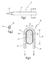
- Die Erfindung wird nachfolgend anhand einiger Ausführungsbeispiele im Zusammenhang mit den beiliegenden Zeichnungen näher beschrieben und erläutert. Es zeigen:
- Fig. 1
- einen Stift bzw. Cross Pin in Seitenansicht;
- Fig. 2
- einen Schnitt längs der Linie II-II in Fig. 1;
- Fig. 3
- in einem etwas vergrößerten Maßstab einen der Fig. 2 entsprechenden Schnitt eines weiteren Ausführungsbeispiels mit ovalärer Form, wobei ein Sehnenimplantat, das durch den Stift fixiert werden soll, angedeutet ist, und
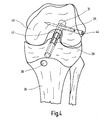
- Fig. 4
- stark schematisiert einen in einen Oberschenkelknochen eingesetzten Stift von Fig. 1 zur Transfixation eines unter Zuglast beanspruchten Implantates.
- Ein in den Fig. 1 und 2 dargestellter Stift bzw. Cross Pin 10 weist einen stabförmigen Körper 12 auf, der an einer Seite in einer konisch zulaufenden Spitze 14 mündet.
- Aus der Darstellung von Fig. 2 ist zu erkennen, dass der Querschnitt eine ovale Form aufweist.
- In Fig. 3 ist ein Stift 20 dargestellt, der ebenfalls einen hier nicht näher dargestellten stabförmigen Körper mit einer Spitze aufweist, und der einen Querschnitt aufweist, der als Flachoval 22 ausgebildet ist.
- Das Flachoval 22 wird gegenüberliegend durch zwei Halbrunde 24 und 25 begrenzt, die über zwei parallel zueinander verlaufenden Seitenflanken 26 und 28 verbunden sind.
- Es ist ferner dargestellt, wie ein Sehnenimplantat 30 um den Cross Pin 20 gelegt ist, und zwar in Form einer Schleife 31.
- Der Cross Pin 20 ist dabei so ausgerichtet, dass dessen lange Achse 32 hochstehend ist, also in Richtung der Krafteinleitung durch das Sehnenimplantat. Die kurze Achse 34 verläuft quer dazu und auch quer zur Längsachse des Cross Pins 20.
- Die Pins weisen beispielsweise eine Länge von ca. 40 mm und einen Durchmesser von etwa 4,5 mm auf.
- Sie können aus resorbierbaren Materialien, aus Kunststoffmaterial oder auch aus metallischem Material, insbesondere Titan oder einer Titanlegierung, hergestellt werden.
- In Fig. 4 ist eine Situation dargestellt, bei der der Stift 20 bzw. Cross Pin zur Fixation eines Sehnenimplantates 30 dient, das als Ersatz eines Kreuzbandes im Knie eines Menschen dient.
- Dazu wurde in der Tibia 36 eine durchgehende Bohrung 38 eingebracht, die sich im Femur 40 als Sacklochbohrung 42 fortsetzt.
- Ferner ist im Femur 40 eine Querbohrung 44 eingebracht, um den Stift bzw. Cross Pin 10 eintreiben zu können, und zwar so, dass er durch die Schleife 32 des Sehnenimplantates 30 hindurch reicht.
- Die Operationstechnik bzw. die notwendigen Hilfsgeräte zum Einbringen der Bohrungen 38, 42 sowie zum zielgerechten Einbringen der Querbohrung 44 bzw. zum Setzen und Befestigen des Implantates und des Cross Pins sind insbesondere in der US 2003/0065391 A1 und in der US 5,601,562 beschrieben, auf deren Inhalt ausdrücklich diesbezüglich Bezug genommen wird.
- Soll ein Cross Pin mit ovalärem Querschnitt eingesetzt werden, wird zunächst mit einem Bohrer die Querbohrung 44 mit rundem Querschnitt bewerkstelligt, und anschließend wird ein Dilatator mit der etwa gleichen Kontur des Cross Pins 20 eingetrieben. Der Dilatator ist dabei etwas kleiner als der Cross Pin 20, so dass beim Einbringen des Cross Pins 20 ein Presssitz entsteht. Der ovaläre Cross Pin wird jeweils so eingebracht, wie dies in Fig. 3 ersichtlich ist, also dass dessen längere Querschnittsachse 32 sich in Richtung der Krafteinwirkung oder Zugrichtung des Sehnenimplantates 30 erstreckt.
Claims (3)
- Stift zum Fixieren eines unter Zuglast beanspruchten Implantates, insbesondere eines Sehnenimplantates (30), mit einem stabförmigen Körper (12), auf dessen Querschnitt (16) auf einer Seite die durch das Implantat ausgeübte Kraft einleitbar ist, und auf der gegenüberliegenden Seite in eine Verankerungsstelle ableitbar ist, dadurch gekennzeichnet, dass der Querschnitt (16) in Richtung der vom Sehnenimplantat (30) eingeleiteten Kraft ein längeres Ausmaß (32) als quer (34) zur Längsachse aufweist.
- Stift nach Anspruch 1, dadurch gekennzeichnet, dass der Querschnitt (16) ovalär ist.
- Stift nach Anspruch 2, dadurch gekennzeichnet, dass der Querschnitt als Flachoval (22) ausgebildet ist.
Applications Claiming Priority (1)
| Application Number | Priority Date | Filing Date | Title |
|---|---|---|---|
| DE102004053464A DE102004053464A1 (de) | 2004-11-03 | 2004-11-03 | Ovalärer Stift zum Fixieren eines unter Zuglast beanspruchten Implantates |
Publications (3)
| Publication Number | Publication Date |
|---|---|
| EP1654989A2 true EP1654989A2 (de) | 2006-05-10 |
| EP1654989A3 EP1654989A3 (de) | 2006-05-24 |
| EP1654989B1 EP1654989B1 (de) | 2008-12-17 |
Family
ID=35677451
Family Applications (1)
| Application Number | Title | Priority Date | Filing Date |
|---|---|---|---|
| EP05023522A Expired - Lifetime EP1654989B1 (de) | 2004-11-03 | 2005-10-27 | Ovaler Stift zum Fixieren eines unter Zuglast beanspruchten Implantates |
Country Status (3)
| Country | Link |
|---|---|
| US (1) | US20060111719A1 (de) |
| EP (1) | EP1654989B1 (de) |
| DE (2) | DE102004053464A1 (de) |
Families Citing this family (1)
| Publication number | Priority date | Publication date | Assignee | Title |
|---|---|---|---|---|
| US8671841B2 (en) | 2008-05-07 | 2014-03-18 | Securinov Sa | Kinetic munition or projectile with controlled, non-lethal effects |
Family Cites Families (35)
| Publication number | Priority date | Publication date | Assignee | Title |
|---|---|---|---|---|
| US490439A (en) * | 1893-01-24 | Railway-spike | ||
| US1591404A (en) * | 1925-05-19 | 1926-07-06 | Sakowski Hugo Karl | Pin |
| CH683963A5 (de) * | 1988-06-10 | 1994-06-30 | Synthes Ag | Fixateur intern. |
| US5085660A (en) * | 1990-11-19 | 1992-02-04 | Lin Kwan C | Innovative locking plate system |
| US5330474A (en) * | 1991-09-23 | 1994-07-19 | Lin Chih I | Vertebral locking and retrieving system |
| US5342384A (en) * | 1992-08-13 | 1994-08-30 | Brigham & Women's Hospital | Surgical dilator |
| US5382248A (en) * | 1992-09-10 | 1995-01-17 | H. D. Medical, Inc. | System and method for stabilizing bone segments |
| US5632748A (en) * | 1993-06-14 | 1997-05-27 | Linvatec Corporation | Endosteal anchoring device for urging a ligament against a bone surface |
| US5486178A (en) * | 1994-02-16 | 1996-01-23 | Hodge; W. Andrew | Femoral preparation instrumentation system and method |
| US5601562A (en) * | 1995-02-14 | 1997-02-11 | Arthrex, Inc. | Forked insertion tool and metnod of arthroscopic surgery using the same |
| US6632224B2 (en) * | 1996-11-12 | 2003-10-14 | Triage Medical, Inc. | Bone fixation system |
| US6554862B2 (en) * | 1996-11-27 | 2003-04-29 | Ethicon, Inc. | Graft ligament anchor and method for attaching a graft ligament to a bone |
| US6533816B2 (en) * | 1999-02-09 | 2003-03-18 | Joseph H. Sklar | Graft ligament anchor and method for attaching a graft ligament to a bone |
| JPH10201783A (ja) * | 1997-01-20 | 1998-08-04 | Masanori Kobayashi | 手指腱保護具 |
| US6001100A (en) * | 1997-08-19 | 1999-12-14 | Bionx Implants Oy | Bone block fixation implant |
| US6306138B1 (en) * | 1997-09-24 | 2001-10-23 | Ethicon, Inc. | ACL fixation pin and method |
| GB9825681D0 (en) * | 1998-11-25 | 1999-01-20 | Biocomposites Ltd | Surgical device |
| DE19900133A1 (de) * | 1999-01-05 | 2000-07-06 | Intraplant Ag Cham | System zur Positionierung und Verriegelung eines intramedulären Kraftträgers, insbesondere Marknagels |
| US6086591A (en) * | 1999-01-29 | 2000-07-11 | Smith & Nephew, Inc. | Soft tissue anchor |
| US6520991B2 (en) * | 1999-05-11 | 2003-02-18 | Donald R. Huene | Expandable implant for inter-vertebral stabilization, and a method of stabilizing vertebrae |
| DE29910202U1 (de) * | 1999-06-11 | 1999-08-05 | Aesculap AG & Co. KG, 78532 Tuttlingen | Füllkörper zum Verengen des Querschnitts eines Knochenkanals |
| WO2001008717A1 (en) * | 1999-08-03 | 2001-02-08 | Smith & Nephew, Inc. | Controlled release implantable devices |
| AU2001231272A1 (en) * | 2000-02-02 | 2001-08-14 | Owen A. Nelson | An orthopedic implant used to repair intertrochanteric fractures and a method for inserting the same |
| US6623524B2 (en) * | 2000-06-09 | 2003-09-23 | Arthrex, Inc. | Method for anterior cruciate ligament reconstruction using cross-pin implant with eyelet |
| CA2353206C (en) * | 2000-07-19 | 2009-07-14 | Ethicon, Inc. | Apparatus and method for reconstructing a ligament |
| US6878166B2 (en) * | 2000-08-28 | 2005-04-12 | Ron Clark | Method and implant for securing ligament replacement into the knee |
| US6641596B1 (en) * | 2000-10-18 | 2003-11-04 | Ethicon, Inc. | Knotless bioabsorbable suture anchor system and method |
| DE20101791U1 (de) * | 2001-02-02 | 2001-05-03 | Aesculap AG & Co. KG, 78532 Tuttlingen | Implantat |
| DE10109804C2 (de) * | 2001-03-01 | 2003-04-03 | Mathys Medizinaltechnik Ag Bet | Gelenkprothese |
| US7678138B2 (en) * | 2002-05-15 | 2010-03-16 | Linvatec Corporation | Two piece cross-pin graft fixation |
| ATE462383T1 (de) * | 2002-09-24 | 2010-04-15 | Bogomir Gorensek | Stabilisierungsvorrichtung für bandscheiben und verfahren dafür |
| US20040138683A1 (en) * | 2003-01-09 | 2004-07-15 | Walter Shelton | Suture arrow device and method of using |
| WO2004098453A2 (en) * | 2003-05-06 | 2004-11-18 | Triage Medical, Inc. | Proximal anchors for bone fixation system |
| US7632277B2 (en) * | 2004-03-29 | 2009-12-15 | Woll Bioorthopedics Llc | Orthopedic intramedullary fixation system |
| DE102004053471A1 (de) * | 2004-11-03 | 2006-05-04 | Karl Storz Gmbh & Co. Kg | Stift zum Fixieren eines unter Zuglast beanspruchten Implantates |
-
2004
- 2004-11-03 DE DE102004053464A patent/DE102004053464A1/de not_active Withdrawn
-
2005
- 2005-10-27 EP EP05023522A patent/EP1654989B1/de not_active Expired - Lifetime
- 2005-10-27 DE DE502005006263T patent/DE502005006263D1/de not_active Expired - Lifetime
- 2005-11-03 US US11/266,722 patent/US20060111719A1/en not_active Abandoned
Also Published As
| Publication number | Publication date |
|---|---|
| US20060111719A1 (en) | 2006-05-25 |
| EP1654989B1 (de) | 2008-12-17 |
| DE502005006263D1 (de) | 2009-01-29 |
| DE102004053464A1 (de) | 2006-05-04 |
| EP1654989A3 (de) | 2006-05-24 |
Similar Documents
| Publication | Publication Date | Title |
|---|---|---|
| EP1082063B1 (de) | Chirurgische blindniete mit schliesselement | |
| DE19603285B4 (de) | Intramedullärer Nagel | |
| EP1024762B1 (de) | Knochenfixationsvorrichtung | |
| EP1658013B1 (de) | Marknagel | |
| DE60129998T2 (de) | Gerät zur implantation in knochen | |
| DE69115302T2 (de) | Intramedulläre Hüftschraube | |
| DE60213800T2 (de) | Nagel und Schraube für chirurgisches Fixationssystem | |
| EP1631206B1 (de) | Chirurgischer nagel | |
| DE20022673U1 (de) | Schraubverbindung für die Osteosynthese | |
| EP1315462B1 (de) | Vorrichtung zur fixierung von chirurgischen implantaten | |
| DE19831336A1 (de) | Knochenschraube, insbesondere für den Einsatz bei translaminärer Wirbelverschraubung | |
| EP1334702A1 (de) | Ankerelement zum Verankern eines Ligamenttransplantates | |
| EP0745356A2 (de) | Osteosynthese-Hilfsmittel zur Versorgung subtrochanterer, pertrochanterer und Schenkelhalsfrakturen | |
| DE2454181B2 (de) | Keramisches Implantat | |
| EP1287787A1 (de) | Implantat zur gegenseitigen Fixierung zweier Knochenfragmente | |
| DE10161970A1 (de) | Knochenanker | |
| AT520250B1 (de) | Knochenschraube | |
| DE102014113556A1 (de) | Osteosynthese-Hilfsmittel zur Versorgung subtrochantärer Frakturen und/oder pertrochantärer Frakturen und/oder Oberschenkelhalsfrakturen | |
| EP1732466B1 (de) | Instrumentarium zum fixieren eines implantates in einem knochen | |
| DE69405263T2 (de) | Femurales Schaftteil einer Hüftgelenkprothese | |
| EP3600161B1 (de) | Verbindungshülse für verankerungsschäfte zweier gegenüberliegend angeordneter prothesen | |
| EP1790315B1 (de) | Vorrichtung zum Verblocken eines Sehnentransplantates | |
| EP1654989B1 (de) | Ovaler Stift zum Fixieren eines unter Zuglast beanspruchten Implantates | |
| DE10035610B4 (de) | Knochendübel für die Verankerung von Sehnen | |
| DE102008017014B4 (de) | Oberflächenersatzprothese |
Legal Events
| Date | Code | Title | Description |
|---|---|---|---|
| PUAI | Public reference made under article 153(3) epc to a published international application that has entered the european phase |
Free format text: ORIGINAL CODE: 0009012 |
|
| PUAL | Search report despatched |
Free format text: ORIGINAL CODE: 0009013 |
|
| AK | Designated contracting states |
Kind code of ref document: A2 Designated state(s): AT BE BG CH CY CZ DE DK EE ES FI FR GB GR HU IE IS IT LI LT LU LV MC NL PL PT RO SE SI SK TR |
|
| AX | Request for extension of the european patent |
Extension state: AL BA HR MK YU |
|
| AK | Designated contracting states |
Kind code of ref document: A3 Designated state(s): AT BE BG CH CY CZ DE DK EE ES FI FR GB GR HU IE IS IT LI LT LU LV MC NL PL PT RO SE SI SK TR |
|
| AX | Request for extension of the european patent |
Extension state: AL BA HR MK YU |
|
| RIC1 | Information provided on ipc code assigned before grant |
Ipc: A61F 2/08 20060101ALI20060401BHEP Ipc: A61B 17/04 20060101AFI20060206BHEP |
|
| 17P | Request for examination filed |
Effective date: 20061121 |
|
| AKX | Designation fees paid |
Designated state(s): DE FR GB IT |
|
| 17Q | First examination report despatched |
Effective date: 20070118 |
|
| GRAP | Despatch of communication of intention to grant a patent |
Free format text: ORIGINAL CODE: EPIDOSNIGR1 |
|
| RTI1 | Title (correction) |
Free format text: OVAL PIN FOR THE FIXATION OF AN IMPLANT UNDER LOAD |
|
| GRAS | Grant fee paid |
Free format text: ORIGINAL CODE: EPIDOSNIGR3 |
|
| GRAS | Grant fee paid |
Free format text: ORIGINAL CODE: EPIDOSNIGR3 |
|
| GRAA | (expected) grant |
Free format text: ORIGINAL CODE: 0009210 |
|
| AK | Designated contracting states |
Kind code of ref document: B1 Designated state(s): DE FR GB IT |
|
| REG | Reference to a national code |
Ref country code: GB Ref legal event code: FG4D Free format text: NOT ENGLISH |
|
| REF | Corresponds to: |
Ref document number: 502005006263 Country of ref document: DE Date of ref document: 20090129 Kind code of ref document: P |
|
| PLBE | No opposition filed within time limit |
Free format text: ORIGINAL CODE: 0009261 |
|
| STAA | Information on the status of an ep patent application or granted ep patent |
Free format text: STATUS: NO OPPOSITION FILED WITHIN TIME LIMIT |
|
| 26N | No opposition filed |
Effective date: 20090918 |
|
| REG | Reference to a national code |
Ref country code: FR Ref legal event code: PLFP Year of fee payment: 12 |
|
| PGFP | Annual fee paid to national office [announced via postgrant information from national office to epo] |
Ref country code: GB Payment date: 20160928 Year of fee payment: 12 |
|
| PGFP | Annual fee paid to national office [announced via postgrant information from national office to epo] |
Ref country code: FR Payment date: 20160921 Year of fee payment: 12 |
|
| PGFP | Annual fee paid to national office [announced via postgrant information from national office to epo] |
Ref country code: IT Payment date: 20160923 Year of fee payment: 12 |
|
| REG | Reference to a national code |
Ref country code: DE Ref legal event code: R082 Ref document number: 502005006263 Country of ref document: DE Representative=s name: WITTE, WELLER & PARTNER PATENTANWAELTE MBB, DE Ref country code: DE Ref legal event code: R081 Ref document number: 502005006263 Country of ref document: DE Owner name: KARL STORZ SE & CO. KG, DE Free format text: FORMER OWNER: KARL STORZ GMBH & CO. KG, 78532 TUTTLINGEN, DE |
|
| GBPC | Gb: european patent ceased through non-payment of renewal fee |
Effective date: 20171027 |
|
| REG | Reference to a national code |
Ref country code: FR Ref legal event code: ST Effective date: 20180629 |
|
| PG25 | Lapsed in a contracting state [announced via postgrant information from national office to epo] |
Ref country code: GB Free format text: LAPSE BECAUSE OF NON-PAYMENT OF DUE FEES Effective date: 20171027 |
|
| PG25 | Lapsed in a contracting state [announced via postgrant information from national office to epo] |
Ref country code: FR Free format text: LAPSE BECAUSE OF NON-PAYMENT OF DUE FEES Effective date: 20171031 |
|
| PG25 | Lapsed in a contracting state [announced via postgrant information from national office to epo] |
Ref country code: IT Free format text: LAPSE BECAUSE OF NON-PAYMENT OF DUE FEES Effective date: 20171027 |
|
| PGFP | Annual fee paid to national office [announced via postgrant information from national office to epo] |
Ref country code: DE Payment date: 20190918 Year of fee payment: 15 |
|
| REG | Reference to a national code |
Ref country code: DE Ref legal event code: R119 Ref document number: 502005006263 Country of ref document: DE |
|
| PG25 | Lapsed in a contracting state [announced via postgrant information from national office to epo] |
Ref country code: DE Free format text: LAPSE BECAUSE OF NON-PAYMENT OF DUE FEES Effective date: 20210501 |