EP1654976B1 - Endoscope with alternating driving - Google Patents
Endoscope with alternating driving Download PDFInfo
- Publication number
- EP1654976B1 EP1654976B1 EP05022928.5A EP05022928A EP1654976B1 EP 1654976 B1 EP1654976 B1 EP 1654976B1 EP 05022928 A EP05022928 A EP 05022928A EP 1654976 B1 EP1654976 B1 EP 1654976B1
- Authority
- EP
- European Patent Office
- Prior art keywords
- endoscope
- tube
- endoscope shaft
- fluid
- hose
- Prior art date
- Legal status (The legal status is an assumption and is not a legal conclusion. Google has not performed a legal analysis and makes no representation as to the accuracy of the status listed.)
- Not-in-force
Links
Images


Classifications
-
- A—HUMAN NECESSITIES
- A61—MEDICAL OR VETERINARY SCIENCE; HYGIENE
- A61B—DIAGNOSIS; SURGERY; IDENTIFICATION
- A61B1/00—Instruments for performing medical examinations of the interior of cavities or tubes of the body by visual or photographical inspection, e.g. endoscopes; Illuminating arrangements therefor
- A61B1/005—Flexible endoscopes
- A61B1/01—Guiding arrangements therefore
-
- A—HUMAN NECESSITIES
- A61—MEDICAL OR VETERINARY SCIENCE; HYGIENE
- A61B—DIAGNOSIS; SURGERY; IDENTIFICATION
- A61B1/00—Instruments for performing medical examinations of the interior of cavities or tubes of the body by visual or photographical inspection, e.g. endoscopes; Illuminating arrangements therefor
- A61B1/00064—Constructional details of the endoscope body
- A61B1/00071—Insertion part of the endoscope body
- A61B1/0008—Insertion part of the endoscope body characterised by distal tip features
- A61B1/00082—Balloons
-
- A—HUMAN NECESSITIES
- A61—MEDICAL OR VETERINARY SCIENCE; HYGIENE
- A61B—DIAGNOSIS; SURGERY; IDENTIFICATION
- A61B1/00—Instruments for performing medical examinations of the interior of cavities or tubes of the body by visual or photographical inspection, e.g. endoscopes; Illuminating arrangements therefor
- A61B1/00064—Constructional details of the endoscope body
- A61B1/00071—Insertion part of the endoscope body
- A61B1/0008—Insertion part of the endoscope body characterised by distal tip features
- A61B1/00085—Baskets
-
- A—HUMAN NECESSITIES
- A61—MEDICAL OR VETERINARY SCIENCE; HYGIENE
- A61B—DIAGNOSIS; SURGERY; IDENTIFICATION
- A61B1/00—Instruments for performing medical examinations of the interior of cavities or tubes of the body by visual or photographical inspection, e.g. endoscopes; Illuminating arrangements therefor
- A61B1/00147—Holding or positioning arrangements
- A61B1/00154—Holding or positioning arrangements using guiding arrangements for insertion
-
- A—HUMAN NECESSITIES
- A61—MEDICAL OR VETERINARY SCIENCE; HYGIENE
- A61B—DIAGNOSIS; SURGERY; IDENTIFICATION
- A61B1/00—Instruments for performing medical examinations of the interior of cavities or tubes of the body by visual or photographical inspection, e.g. endoscopes; Illuminating arrangements therefor
- A61B1/00147—Holding or positioning arrangements
- A61B1/0016—Holding or positioning arrangements using motor drive units
Description
Die Erfindung bezieht sich auf ein Endoskop mit alternierendem Vortrieb zum Bewegen eines Endoskopschafts längs eines kanalartigen Hohlraums gemäß dem Oberbegriff des Patentanspruchs 1.The invention relates to an endoscope with alternating propulsion for moving an endoscope shaft along a channel-like cavity according to the preamble of
Endoskope sind zu einem wichtigen Hilfsmittel in der Technik und vor allem in der Medizin geworden, um kanalartige Hohlräume zu inspizieren, die ansonsten nur mit erheblichen Eingriffen zugänglich sind. Bevorzugt werden Endoskope zur Untersuchung der Speiseröhre, des Magens, des Zwölffingerdarms vom Magen aus, des Darms vom Anus aus, der Harnröhre, der Blase und des Harnleiters verwendet.Endoscopes have become an important tool in the art and especially in medicine to inspect channel-like cavities that are otherwise accessible only with considerable intervention. Preferably, endoscopes are used to examine the esophagus, stomach, duodenum from the stomach, intestine, anus, urethra, bladder and urethra.
Derartige Endoskope sind an ihrem Vorderende mit einer Beleuchtungseinrichtung und mit einer Optik zur visuellen Erfassung des davorliegenden Bereichs des Hohlraums ausgerüstet. Die am Vorderende des Endoskops erfasste, optische Information wird normalerweise entweder mittels einer Faseroptik durch das Endoskop nach hinten zu seinem Bedienungsende übertragen oder wird mittels eines optischen Sensorchips am Vorderende erfasst, durch eine elektrische Leitung durch das Endoskop nach hinten geleitet und auf einem Bildschirm sichtbar gemacht. Darüber hinaus ist auch eine Informationsübertragung per Funk vom Vorderende zum Bedienungsende denkbar.Such endoscopes are equipped at their front end with a lighting device and with an optical system for the visual detection of the area in front of the cavity. The optical information acquired at the front end of the endoscope is normally either transmitted back to its operating end by means of a fiber optic through the endoscope or is detected by means of an optical sensor chip at the front end, guided backwards through the endoscope by an electrical line and made visible on a screen , In addition, an information transmission by radio from the front end to the operator end is conceivable.
Ferner weisen Endoskope in der Regel einen sogenannten Arbeitskanal auf, durch den diverse Arbeitsinstrumente eingeführt und bedient werden können. Beispielsweise werden kleine Zangen zur Entnahmen von Gewebeproben, Biopsienadeln, beheizbare Schneiddrähte, kleine Scheren, Koagulationselektroden oder dergleichen eingeführt, um ggf. operative Maßnahmen an beschädigtem Gewebe durchzuführen. Schließlich sind in der Regel ein Fluidkanal für Spülflüssigkeit und Bedienungsdrähte oder Fluidleitungen zum Abwinkeln des Endoskopvorderendes in mehrere Richtungen vorhanden. Diese Bedienungsdrähte oder Fluidleitungen werden wiederum innerhalb des Endoskopschafts zu dessen vorderem bzw. distalem Ende geführt.Furthermore, endoscopes usually have a so-called working channel through which diverse Working instruments can be introduced and operated. For example, small forceps for taking tissue samples, biopsy needles, heatable cutting wires, small scissors, coagulation electrodes or the like are introduced to perform possibly surgical measures on damaged tissue. Finally, a fluid conduit for irrigation fluid and operating wires or fluid conduits for angling the endoscope tip in several directions are typically present. These operating wires or fluid conduits are in turn guided within the endoscope shaft to its front and / or distal end.
Zum Einführen und Vorwärtsbewegen des Endoskopschafts im zu inspizierenden kanalartigen Hohlraum offenbart die
Neuere Untersuchungen zeigten jedoch, dass nicht die Relativbewegung zwischen dem eingeführten Endoskopschaft und der Darmwand die Hauptursache für die Schmerzen bei einer Darmspiegelung darstellen, sondern dass die Schmerzen vor allem durch Drücken des Distalendes des Endoskopschafts gegen die Krümmungsaußenwand von Darmbiegungen entstehen. (Die Begriffe Krümmungsaußenwand und -innenwand bezeichnen in diesem Zusammenhang jeweils die bezüglich eines fiktiven Mittelpunktes einer Hohlraumbiegung jeweils weiter außen- bzw. innenliegende Hohlraumwandung.)However, recent studies have shown that it is not the relative movement between the inserted endoscope shaft and the intestinal wall that is the main cause of the pain in a colonoscopy, but that the pain is mainly due to the distal end of the abdomen Endoscope shaft against the curvature outer wall of intestinal bends arise. (The terms outer wall curvature and inner wall in this context each denote in relation to a fictitious center of a cavity bend each further outward or inward cavity wall.)
Als weiteren relevanten Stand der Technik seien noch die folgenden Druckschriften genannt:
- Die
US 4,815,450
- The
US 4,815,450
Die
Die
Daher ist es eine Aufgabe der Erfindung, ein Endoskop mit einem Vortriebsystem einfachen Aufbaus zu realisieren, mit dem weniger Druck gegen die Krümmungsaußenwand ausgeübt wird.Therefore, it is an object of the invention to realize an endoscope with a propulsion system of simple construction, with which less pressure is exerted against the curvature outer wall.
Diese Aufgabe wird durch ein Endoskop mit alternierendem Vortriebsystem mit den Merkmalen des Anspruchs 1 gelöst. Die Erfindung beruht dabei auf folgender Grundüberlegung.This object is achieved by an endoscope with alternating propulsion system with the features of
Endoskopschäfte müssen prinzipiell zwei zueinander gegensätzliche Bedingungen erfüllen. Zum Einen müssen sie in einen zu untersuchenden Hohlraum geschoben werden, was eine bestimmte Steifigkeit des Schafts voraussetzt, um nicht auszuknicken. Zum Anderen müssen sie flexibel genug sein, Krümmungen folgen zu können. Letztere Bedingung ist insbesondere bei Untersuchungen von Darmwandungen wichtig, da eine zu geringe Flexibilität dazu führt, dass ein Endoskopschaft an einer zu passierenden Darmkrümmung die Darmwand ausbeult, was, wie vorstehend ausgeführt wurde, zu erheblichen Schmerzen führt.Endoscope shanks must meet in principle two mutually opposite conditions. First, they must be pushed into a cavity to be examined, which requires a certain stiffness of the shaft so as not to buckle. On the other hand, they must be flexible enough to be able to follow bends. The latter condition is particularly important in examinations of intestinal walls, since too low a flexibility results in an endoscope shaft bulging out of the bowel wall at a bowel obstruction to be passed, which, as stated above, leads to considerable pain.
Gemäß einem Aspekt der Erfindung wird ein Endoskopschaft mit Hilfe einer Hilfseinrichtung vorzugsweise in Form eines Schlauchs oder Schlaucheinrichtung in einem kanalartigen Hohlraum vorangetrieben wird, welcher den Schaft außenwandig umgibt. Entscheidend dabei ist, dass dieser Schlauch/Schlaucheinrichtung zumindest temporär steifer ist oder gemacht werden kann, wie der vorzugsweise hochflexible Endoskopschaft. Durch diese Ausgestaltung wird ein Ausknicken des Endoskopschafts durch den diesen umgebenden und stützenden Schlauchs/Schlaucheinrichtung verhindert, gleichzeitig kann eine immer noch ausreichend hohe Flexibilität beibehalten werden.According to one aspect of the invention, an endoscope shaft is driven by means of an auxiliary device preferably in the form of a hose or hose device in a channel-like cavity, which the Sheath surrounding the outside wall. It is crucial that this hose / hose device is at least temporarily stiffer or can be made, as the preferably highly flexible endoscope shaft. As a result of this configuration, buckling of the endoscope shaft is prevented by the tube / hose device surrounding it and supporting it; at the same time, a sufficiently high degree of flexibility can still be maintained.
Der Kern der Erfindung zur Umsetzung des vorstehenden prinzipiellen Erfindungsgedankens besteht demzufolge darin, den außenseitigen Schlauch/Schlauchhilfseinrichtung relativ bewegbar zum darin liegenden Endoskopschaft zu gestalten, wobei der Endoskopschaft als das erste Element und die Hilfseinrichtung als das zweite Element abwechselnd bezüglich eines zu inspizierenden Hohlraums ruhend sind, d.h. sich nicht nach vorn bewegt, und gleichzeitig das gerade nicht ruhende Element unter Führung entlang des gerade ruhenden Elements in den Hohlraum vorantreibbar ist.The core of the invention for implementing the above basic concept of the invention is therefore to make the outside hose / tube auxiliary relatively movable to the endoscope shaft lying therein, wherein the endoscope shaft as the first element and the auxiliary device as the second element are alternately with respect to a cavity to be inspected ie does not move forward, and at the same time the just non-resting element is vorreibreibbar under guidance along the straight resting element into the cavity.
Erfindungsgemäß ist es vorgesehen, dass eines der beiden Elemente, nämlich der den Endoskopschaft umgebende Schlauch/Schlaucheinrichtung, nur temporär eine größere Steifigkeit erhält als jene des Endoskopschafts. Konkreter ausgedrückt ist die Grundsteifigkeit des Schlauchs geringer als die des Endoskopschafts. In dieser Situation dient der Endoskopschaft als Führungselement, d.h. ist der Endoskopschaft in der Lage den relativ zu diesem sich bewegenden Schlauch auch durch Krümmungen zu führen. Darüber hinaus weist der Schlauch eine Vorrichtung auf, mittels der der flexible Schlauch ausgesteift werden kann, insbesondere auf eine solche Steifigkeit, die größer ist als die des Endoskopschafts.According to the invention, it is provided that one of the two elements, namely the hose / hose device surrounding the endoscope shaft, only temporarily receives a greater rigidity than that of the endoscope shaft. More concretely, the basic stiffness of the tube is less than that of the endoscope shaft. In this situation, the endoscope shaft serves as a guide element, ie, the endoscope shaft is able to guide the relative to this moving tube by curvatures. In addition, the hose has a device by means of which the flexible hose can be stiffened, in particular to a stiffness which is greater than that of the endoscope shaft.
In dieser Situation dient der Schlauch als Führungselement, d.h. ist der Schlauch in der Lage, den relativ zu diesem sich bewegenden Schaft durch Krümmungen zu führen. Dabei stehen dem Fachmann eine Vielzahl von derartigen Vorrichtungen zur wahlweisen (temporären) (alternierenden) Aussteifung des Schlauchs und/oder des Schafts zur Verfügung. Erfindungsgemäß, ist der Schlauch mit Fluidkissen ausgekleidet oder bedeckt, deren Inhalt (Volumen) wahlweise eingespannt und wieder freigegeben werden kann.In this situation, the hose serves as a guide element, ie, the hose is able to guide the relative to this moving shaft by curvatures. A variety of such devices for selectively (temporarily) (alternately) stiffening the hose and / or the shaft are available to the person skilled in the art. According to the invention, the tube is lined or covered with fluid cushions whose contents (volume) can optionally be clamped and released again.
Weitere vorteilhafte Ausgestaltungen der Erfindung sind Gegenstand der übrigen Patentansprüche.Further advantageous embodiments of the invention are the subject of the other claims.
Die Erfindung wird nachstehend anhand eines bevorzugten Ausführungsbeispiels bezugnehmend auf die beigefügten Zeichnungen genauer beschrieben, dabei ist in den Zeichnungen folgendes schematisch dargestellt:
-
Fig. 1 ist eine räumliche Darstellung eines bevorzugten Ausführungsbeispiels des Endoskops der vorliegenden Erfindung; -
Fig. 2 stellt Antriebseinrichtungen zum Vorwärtsbewegen des Endoskops gemäß des bevorzugten Ausführungsbeispiels dar; - Die
Fig. 3A bis 3C sind Vorderansichten des Endoskops, welche die Vorwärtsbewegung des Endoskops gemäß des bevorzugten Ausführungsbeispiels veranschaulichen; - Die
Fig. 4A bis 4C sind Vorderansichten des Endoskops, welche die Vorwärtsbewegung des Endoskops gemäß einer Modifikation des bevorzugten Ausführungsbeispiels veranschaulichen und
-
Fig. 1 Figure 3 is a perspective view of a preferred embodiment of the endoscope of the present invention; -
Fig. 2 illustrates drive means for advancing the endoscope according to the preferred embodiment; - The
Figs. 3A to 3C Figure 11 are front views of the endoscope illustrating the forward movement of the endoscope according to the preferred embodiment; - The
FIGS. 4A to 4C FIG. 16 are front views of the endoscope illustrating the forward movement of the endoscope according to a modification of the preferred embodiment; and FIG
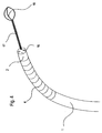
Anhand der
Der Endoskopkopf 2 ist vorzugsweise über einen beweglichen distalen Endabschnitt 4 (nachfolgend als "Deflecting" bezeichnet) mit dem flexiblen Endoskopschaft 1 verbunden. Das Deflecting 4 kann ansprechend auf Anweisungen vom Bedienungsende (nicht dargestellt) des Endoskops in verschiedenen Krümmungsradien vorzugsweise in mehrere Richtungen gekrümmt werden. Verwendung findet hierbei ein herkömmliches Deflecting, wie beispielsweise in den Anmeldungen
Die Leitungen (nicht dargestellt) zum Ansteuern des Deflectings 4 und der Einrichtungen 3 sowie eventuell vorhandene Arbeitskanäle zum Bedienen und Einführen von am Endoskopkopf 2 verwendeten Werkzeugen verlaufen innerhalb des Deflectings 4 und des Endoskopschafts 1 zum Bedienungsende nach hinten.The lines (not shown) for driving the
Der Endoskopschaft 1 wird bevorzugterweise bis zu der Stelle, an der der Endoskopschaft 1 mit dem Deflecting 4 verbunden ist von einem vorzugsweise einwandigen Schlauch 5 umgeben, so dass am Vorderende (distales Ende) des Schlauchs 5 das Deflecting 4 mit dem damit verbundenen Endoskopkopf 2 herausragen. Der Schlauch besteht in diesem Ausführungsbeispiel aus EPTFE-Material, dessen Wandstärke 2 - 3mm beträgt. Zur Verstärkung kann eine Spiralfeder in das schlauchförmige EPTFE-Material derart eingebracht sein, dass das EPTFE-Schlauchmaterial konisch zur Spiralfeder verläuft und der Federdraht (nicht notwendiger Weise aus Federstahl gefertigt) zwischen Schlauchinnenwand und Schlauchaußenwand komplett im EPTFE-Material eingebettet wird. Außerdem ist es auch denkbar, die Spiralfeder konisch zum EPTFE-Schlauchmaterial anzuordnen, wobei die Spiralfeder vom EPTFE-Schlauchmaterial eingehüllt und mit diesem verbunden ist, so dass die Spiralfeder nach Innen freigelegt ist. Darüber hinaus ist die Spiralfeder nicht unbedingt erforderlich und es ist auch eine Ausführung des Schlauchs 5 ohne Spiralfeder denkbar. Das Schlauchmaterial ist ebenfalls nicht auf das genannte EPTFE-Material begrenzt und kann aus anderen Materialien wie beispielsweise Silikon ausgebildet sein.The
Der Schlauch 5 ist in diesem Ausführungsbeispiel am Außenumfang mit Fluidkissen 6 versehen. Diese Fluidkissen 6 sind vorzugsweise in einer länglichen Gestalt ausgebildet und an deren Mittelabschnitten 7 verbreitert. Somit weisen die Fluidkissen 6 an ihrem Vorder- und Hinterende einen schmalen zungenförmigen Endabschnitt 8 auf.The
Im vorliegenden Ausführungsbeispiel sind die Fluidkissen 6 jeweils in Gruppen, bestehend aus drei Fluidkissen 6 angeordnet. Die Fluidkissen 6 dieser Dreier-Gruppe werden in der Längsrichtung parallel zueinander um den Außenumfang des Schlauchs 5 ausgerichtet, so dass sich die Seitenflächen der Fluidkissen 6 an ihrem Mittelabschnitt 7 berühren oder einen kleinen Zwischenraum ausbilden. Das heißt, diese Dreier-Gruppe an Fluidkissen ist derart um den Außenumfang des Schlauchs verteilt, dass die Mittelsenkrechten der Fluidkissen 6 sich mit der Mittelachse des Endoskopschafts 1 schneiden und zur Mittelsenkrechten des jeweils benachbarten Fluidkissens 6 einen Winkel von 120° bilden. Bei dieser Gruppe ragen somit die zungenförmigen Endabschnitte 8 im Abstand von 120° (in einer Ebene senkrecht zur Schlauch-Mittelachse) um den Außenumfang des Schlauchs 5 verteilt nach vorn und hinten. Da die Endabschnitte 8 schmäler als die Mittelabschnitte 7 sind, ist ein Endabschnitt zum jeweils benachbarten Endabschnitt weiter beabstandet als die jeweiligen Mittelabschnitte 7. Dadurch werden jeweils zwischen zwei benachbarten Endabschnitten 8 Ausbuchtungen 9 ausgebildet.In the present exemplary embodiment, the
Benachbart zur obigen Dreier-Gruppe an Fluidkissen 6 ist vor und hinter dieser eine weitere Dreier-Gruppe an Fluidkissen 6 derart angeordnet, dass die Endabschnitte 8 der letzteren Dreier-Gruppe an Fluidkissen 6 in die Ausbuchtungen der ersteren Dreier-Gruppe an Fluidkissen 6 eingefügt sind. Das heißt in Längsrichtung benachbarte Fluidkissen-Gruppen sind in Umfangsrichtung in einer Ebene senkrecht zur Schlauch-Mittelachse um 60° versetzt.Adjacent to the above triple group of
Die Fluidkissen 6 sind entsprechend der soeben beschriebenen Art und Weise etwa über einen 50cm langen Endabschnitt des Schlauchs 5 ausgehend von dessen Vorderende angeordnet.The
Die Fluidkissen 6 sind über Zuleitungen (nicht dargestellt), welche in der Wandung oder am Innen- oder Außenumfang des Schlauchs 5 nach hinten zum Bedienungsende verlaufen, mit Druck zu beaufschlagen.The fluid cushions 6 are pressurized via supply lines (not shown), which run in the wall or on the inner or outer circumference of the
Je nach Druckbeaufschlagung der Fluidkissen 6 kann die Flexibilität des Schlauchs 5 verändert werden. Außerdem legen sich die Luftkissen 6 an die Hohlraumwand an, so dass der Schlauch 5 gegenüber der Hohlraumwand feststehend ist. Eine Druckbeaufschlagung der Fluidkissen 6 bzw. ein Entspannen von inkompressiblem Fluid in den Fluidkissen 6 ermöglicht somit, den Schlauch 5 wahlweise mit einer Flexibilität auszustatten, die kleiner oder größer als die Flexibilität des Endoskopschafts 1 ist sowie gleichzeitig den Schlauch 5 gegenüber der Hohlraumwand in einen feststehenden oder bewegbaren Zustand zu versetzen.Depending on the pressurization of the
Dadurch dass sich die Luftkissen an den zungenförmigen Endabschnitten 8 überlappen kann sich der Schlauch 5 auf dem ganzen Umfang der Hohlraumwand abstützen, ohne seine Biegsamkeit zu verlieren.The fact that the air cushion overlap at the tongue-shaped
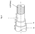
Auf der dem Schlauch 5 abgewandten Seite der Platte 12 ist vorzugsweise ein Paar Antriebsräder 13 vorgesehen, die mit ihrem rinnenförmigen Außenumfang von zwei Seiten her mit dem Endoskopschaft 1 in reibschlüssigem Eingriff sind. Diese Antriebsräder 13 bilden zusammen mit einem nicht eingezeichneten Elektromotor und der mit den Antriebsrädern 13 verbundenen Platte 12 eine zweite Antriebseinrichtung 14.On the side facing away from the
Die erste Antriebseinrichtung 10 ist mit der zweiten Antriebseinrichtung 14 fest verbunden, so dass sich diese Antriebseinrichtungen nicht relativ zueinander bewegen können. Außerdem sind diese Antriebseinrichtungen 10, 14 möglichst so bezüglich des zu untersuchenden Hohlraums anzubringen, dass sie sich nicht relativ zum Hohlraum bewegen.The
Die Oberfläche der Antriebsräder 11 an ihrem rinnenförmigen Außenumfang ist derart gestaltet, dass eine große Reibung zwischen den Antriebsrädern 11 und dem Schlauch 5 besteht. Zwischen dem Schlauch 5 und dem Endoskopschaft 1 ist entweder Schmiermittel eingebracht und/oder der Endoskopschaft 1 ist derart beschichtet (z.B. Teflon), dass zwischen Schlauch 5 und Endoskopschaft 1 eine sehr gering Reibung auftritt. Somit ist es möglich, dass der Schlauch 5 reibschlüssig mittels der Antriebsräder 11 angetrieben wird, während der Endoskopschaft 1 mittels der Antriebsräder 13 in die entgegengesetzte Richtung bewegt wird oder stillsteht.The surface of the
Die Funktionsweise des bevorzugten Ausführungsbeispiels wird unter Bezugnahme auf
In
Von diesem Zustand ausgehend wird der Endoskopschaft 1 mittels der zweiten Antriebseinheit 14 vorwärtsbewegt. Die erste Antriebseinheit 10 steht dabei still. Dieser Vorgang ist in
Sollte es während dieser Vorwärtsbewegung des Endoskopschafts 1 erforderlich sein, den vorderen Teil des Endoskopschafts 1 entlang einer Hohlraumbiegung zu führen wird folgendermaßen verfahren. Zunächst kann die Hohlraumbiegung am Endoskopkopf 2 durch Sensoren oder durch die im Endoskopkopf installierte Optik erkannt werden. Wenn der Endoskopkopf 2 entlang der Hohlraumbiegung vorwärts bewegt wird, kann die Krümmung des Deflectings 4 eingestellt und dem Krümmungsradius der Hohlraumbiegung angepasst werden. Somit wird kein oder nur wenig Druck auf die Krümmungsaußenwand des Hohlraums ausgeübt. Wenn der Endoskopkopf 2 ein Ende der Hohlraumbiegung erreicht hat, wird beim weiteren Vorwärtsbewegen des Endoskopkopfs 2 das Deflecting 4 wieder gerade ausgerichtet.Should it be necessary during this forward movement of the
Wenn der Endoskopschaft 1 mittels der zweiten Antriebseinheit 14 eine bestimmte vorgegebene Strecke aus dem Schlauch 5 herausbewegt wurde (vorgeeilt ist), wird die zweite Antriebseinheit gestoppt, wodurch der Schaft 1 festgehalten wird.When the
Die weitere Vorwärtsbewegung ist in
Bei dieser Vorwärtsbewegung des Schlauchs 5 wirkt der bezüglich des Hohlraums ruhende Endoskopschaft 1 mit seiner geringeren Flexibilität (höhere Grundsteifigkeit verglichen mit der des Schlauchs 5) als Schiene für den Schlauch 5. Da sich der Endoskopschaft 1 weiter im Hohlraum befindet als der Schlauch 5, hat der Endoskopschaft 1 zum Zeitpunkt, bei dem der Schlauch 5 in Bewegung gesetzt wird, bereits die Form des Hohlraums, den der Schlauch 5 in einem Zyklus durchfährt, mit allen eventuellen Biegungen angenommen. Wenn somit der Schlauch 5 der Form des Endoskopschafts 1 folgt, kann somit die Kraft, mit der der Schlauch 5 gegen die Krümmungsaußenwand drückt, verringert werden. Die ansonsten gegen die Krümmungsaußenwand drückende Kraft wird in der vorliegenden Erfindung vom in diesem Zustand steiferen Endoskopschaft 1 abgeleitet. Für die medizinische Anwendung bedeutet dies gleichzeitig, dass die vom Patienten wahrgenommenen Schmerzen nicht entstehen oder vermindert werden.During this forward movement of the
Der Schlauch 5 wird, wie in
Dieser alternierende Vortrieb von Endoskopschaft 1 und Schlauch 5 wird solange wiederholt, bis die gewünschte zu untersuchende Stelle im Hohlraum erreicht ist.This alternating propulsion of
Das Rückwärtsbewegen des Endoskops kann durch Umkehrung des Ablaufs für die Vorwärtsbewegung erfolgen. Eine andere Möglichkeit wäre, die Fluidkissen zu entspannen und das Deflecting 4 so zu lösen, dass es frei beweglich ist. Anschließend könnte der Endoskopschaft zusammen mit dem Schlauch 5 aus dem Hohlraum herausgezogen werden.The backward movement of the endoscope can be accomplished by reversing the forward movement procedure. Another possibility would be to relax the fluid pads and release the deflecting 4 so that it is free to move. Subsequently, the endoscope shaft could be pulled out together with the
Schließlich sei darf hingewiesen, dass die hier vorliegende Beschreibung und die beigefügten Figuren nur beispielhafter Natur sind und keinesfalls dazu dienen sollen, die Erfindung auf die hier vorgestellten Ausführungen zu begrenzen. Die Erfindung lässt eine Vielzahl von Anwendungsmöglichkeiten und Modifikationen zu ohne den Kern der Erfindung zu verlassen.Finally, it should be noted that the present description and the accompanying figures are only exemplary in nature and are in no way intended to limit the invention to the embodiments presented here. The invention allows a variety of applications and modifications without departing from the gist of the invention.
Grundsätzlich kann das vorangehend beschriebene Prinzip des alternierenden Vortriebs des Endoskops in jedem beliebigen Stadium des Vorwärtsbewegens des Endoskops einsetzen bzw. wieder aussetzen. Das heißt, der Endoskopschaft und die Hilfseinrichtung können zuerst in den kanalartigen Hohlraum hineinbewegt werden und der alternierende Vortrieb wird erst an einer bestimmten, schwierig zu passierenden Stelle des Hohlraums eingesetzt. Nach dem Passieren dieser Stelle (z.B. starke Hohlraumbiegungen) ist auch ein Abschalten sowie ein erneutes Anschalten des alternierenden Vortriebs beim weiteren Vorwärtsbewegen möglich.In principle, the previously described principle of alternating propulsion of the endoscope can be used or discontinued at any stage in the forward movement of the endoscope. That is, the The endoscope shaft and the auxiliary device can first be moved into the channel-like cavity and the alternating propulsion is only used at a certain location of the hollow space that is difficult to pass through. After passing this point (eg strong cavity bends) is also a shutdown and a renewed activation of the alternating propulsion during further forward movement possible.
Im bevorzugten Ausführungsbeispiel wurde die Form der Fluidkissen spezifiziert. Jedoch ist jede beliebige andere Formgebung der Fluidkissen denkbar. Beispielsweise könnten die Fluidkissen durch einen Ring ausgebildet werden, der den Schlauch 5 in einer Ebene senkrecht zur Längsachse des Schlauchs umgibt. Dabei müsste der Ring innen hohl und in mehrere Kammern unterteilt sein. Die einzelnen somit entstandenen Kammern würden dann der Funktion jeweils eines Fluidkissens 6 entsprechen und wären ähnlich der Fluidkissen über Zuleitungen mit Druck zu beaufschlagen und zu entspannen.In the preferred embodiment, the shape of the fluid pads has been specified. However, any other shape of the fluid pad is conceivable. For example, the fluid pads could be formed by a ring surrounding the
Darüber hinaus kann auch ganz auf Fluidkissen 6 verzichtet werden und die Flexibilitätsveränderung findet über kanalartige Hohlräume statt, die in Längsrichtung am Außenumfang, am Innenumfang oder in der Wandung des Schlauchs bzw. der Hilfseinrichtung verlaufen. Außerdem könnten diese kanalartigen Hohlräume spiralförmig am Außenumfang, am Innenumfang oder in der Wandung des Schlauchs bzw. der Hilfseinrichtung ausgebildet sein. Ebenso kann eine Flexibilitätsveränderung des Endoskopschafts 1 vorzugsweise mittels dieser kanalartigen Hohlräume, die in Längsrichtung oder spiralförmig entlang des Endoskopschafts 1 verlaufen, realisiert werden, indem die kanalartigen Hohlräume am Außenumfang, im radial äußeren Bereich oder in einem Arbeitskanal angeordnet werden. Zur Flexibilitätsveränderung der Hilfseinrichtung und/oder des Endoskopschafts wird dann das sich in den Hohlräumen befindliche Fluid bzw. Medium druckbeaufschlagt bzw. entspannt.In addition, it is also possible to completely dispense with
Die Länge des vorderen Endabschnittes des Schlauchs 5, über die Fluidkissen 6 angebracht werden, beträgt im bevorzugten Ausführungsbeispiel etwa 50cm. Jedoch ist offensichtlich, dass die Länge dieses vorderen Endabschnittes entsprechend verändert werden kann.The length of the front end portion of the
Desweiteren sind die Fluidkissen 6 im bevorzugten Ausführungsbeispiel am Außenumfang des Schlauchs 5 angebracht. Eine Einbettung der Fluidkissen in der Schlauchwandung ist jedoch ebenfalls möglich.Furthermore, the
Alternativ zum Schlauch 5 könnte im bevorzugten Ausführungsbeispiel eine Spiralfeder verwendet werden. Diese Spiralfeder könnte mit am Außenumfang angeordneten Fluidkissen als Hilfseinrichtung verwendet werden.As an alternative to the
Die Anordnung der Fluidkissen erfolgte im bevorzugten Ausführungsbeispiel in Gruppen zu jeweils drei Fluidkissen. Die Anzahl der Fluidkissen pro Gruppe kann jedoch auch erhöht werden.The arrangement of the fluid pads was carried out in the preferred embodiment in groups of three fluid pads. However, the number of fluid pads per group can also be increased.
Die im bevorzugten Ausführungsbeispiel beschriebene Flexibilitätsveränderung des Schlauchs 5 mittels der Druckbeaufschlagung bzw. Entspannung der Fluidkissen 6 kann auch in mehreren Stufen oder gar kontinuierlich ausgeführt werden. Das heißt die Druckbeaufschlagung der Fluidkissen 6 könnte so gesteuert werden, dass sie umso höher druckbeaufschlagt werden, je weiter der Endoskopkopf 2 bei ruhendem Schlauch 5 in einer Hohlraumbiegung vorwärtsbewegt wird, das heißt je mehr das Deflecting 4 während der Vorwärtsbewegung abgekrümmt wird.The described in the preferred embodiment, flexibility change of the
Im bevorzugten Ausführungsbeispiel schließt das Vorderende (distales Ende) des Schlauchs 5 im eingefahrenen Zustand des Endoskopschafts 1 (Zustand aus
Da der Schlauch 5 bevorzugter Weise aus hoch dehnbarem (hoch flexiblem) EPTFE-Material hergestellt ist, kann der Schlauch stark ausgedehnt werden, ohne seinen Durchmesser bzw. seine Wandstärke zu verändern. Daher kann beispielsweise der Schlauch 5 im bevorzugten Ausführungsbeispiel bis zum Endoskopkopf 2 reichen und dort an diesem fluiddicht befestigt (z.B. durch Ankleben) sein. Dieser Zustand ist in
Wenn nun der Endoskopschaft 1 wie in
Wenn der Schlauch 5 mit entspannten Fluidkissen 6 nach vorne bewegt wird, wie in
Diese Modifikation ist als Zusatz zum ersten Aüsführungsbeispiel zu verstehen und hat den Vorteil, dass der Zwischenraum zwischen Endoskopschaft 1 und Schlauch 5 verschlossen ist, so dass weder Schmiermittel aus dem Zwischenraum austreten kann, noch Verunreinigungen in den Zwischenraum eintreten können.This modification is to be understood as an addition to the first embodiment and has the advantage that the gap between
Beim bevorzugten Ausführungsbeispiel wurde während des Vortriebs des Schlauchs 5 durch die erste Antriebseinheit 10 der Endoskopschaft 1 durch die zweite Antriebseinheit 14 mit gleicher Geschwindigkeit in die entgegengesetzte Richtung angetrieben.In the preferred embodiment, during the advancement of the
Alternativ zum entgegengesetzten Antrieb des Endoskopschafts 1 durch die erste Antriebseinheit 14 könnte auch der Endoskopschaft 1 an dessen Vorderende mit Hilfe des Deflectings 4 bezüglich der Hohlraumwand fixiert werden und die erste Antriebseinheit 14 in Leerlauf geschaltet werden, so dass sich die Antriebsräder 13 frei drehen können. Somit würde der Endoskopschaft 1 ebenfalls gegenüber der Hohlraumwand ruhen während der Schlauch 5 nach vorn bewegt wird.As an alternative to the opposite drive of the
Eine weitere Alternative wäre, den Schlauch 5 nicht mit der Platte 12 zu verbinden. Dabei muss das Hinterende des Schlauchs 5 von der Platte 12 in dem Zustand, bei dem sich der Schlauch 5 bezüglich des Endoskopkopfs 2 in seiner vorderen Stellung befindet, um eine Strecke beabstandet sein, um die sich während eines Bewegungszyklus der Endoskopschaft 1 nach vorn bewegt. Beim Vortrieb des Endoskopschafts 1 wäre bei dieser Alternative das Hinterende des Schlauchs 5 nahe zur Platte 12 angeordnet und die Antriebsräder 11 der ersten Antriebseinheit 10 in Stillstand, so dass der Schlauch 5 bezüglich der Hohlraumwand ruht. Beim Vortrieb des Schlauchs 5 wäre allerdings die zweite Antriebseinheit 14 im Stillstand, so dass sich die Antriebsräder 13 nicht drehen. Die ausgebuchtete Form 15 würde bei dieser Vorwärtsbewegung des Schlauchs 5 nicht in ihrer Größe verändert werden und das Hinterende des Schlauchs 5 würde sich gleichzeitig mit dem Vortrieb in den Hohlraum auch weg von der Platte 12 bewegen.Another alternative would be to not connect the
Im bevorzugten Ausführungsbeispiel wurde die Flexibilitätsveränderung des Schlauchs 5 mittels der Fluidkissen 6 beschrieben. Zusätzlich dazu kann auch die Flexibilität des Endoskopschafts durch am Außenumfang des Endoskopschaft angeordnete oder im Außenumfang integrierte Fluidkissen variiert werden. Die Zuleitungen für diese Fluidkissen des Endoskopschafts müssten im Inneren des Endoskopschafts zum Bedienungsende nach hinten verlaufen. Der alternierende Vortrieb gemäß dieser Modifikation verläuft nach der gleichen Funktionsweise wie das erste Ausführungsbeispiel, wobei das temporär steifere Element aus Endoskopschaft und Schlauch das gleichzeitig flexiblere Element bei der Vorwärtsbewegung unterstützt.In the preferred embodiment, the change in flexibility of the
Claims (5)
- Endoscope having an alternating propulsion comprising an endoscope shaft (1) and an auxiliary means (5), wherein the endoscope is adapted to be propelled into a cavity by alternately retaining the endoscope shaft (1) and the auxiliary means (5) with respect to a canal-shaped cavity to be inspected and simultaneously propelling the element which is currently not being retained by guiding it along the element which is currently being retained, wherein the auxiliary means (5) is a hose which surrounds the endoscope shaft (1) and the basis flexibility of which is higher than the basis flexibility of the endoscope shaft (1), and characterized in that the hose (5) is provided with cavities at its inner or outer circumference or within its wall having the form a plurality of fluid pads (6) which can be filled with a medium for temporarily stiffening the hose (5), such that the flexibility of the hose (5) can be made smaller than the basis flexibility of the endoscope shaft (1) by increasing the pressure of the medium within the respective fluid pads (6), and wherein the fluid pads (6) are adapted to be additionally pressed against a wall of the canal-shaped cavity to be inspected by the pressure built-up within the fluid pads (6).
- An endoscope according to claim 1, characterized in that the fluid pads (6) are distributed in the circumferential direction and are spaced apart in the axial direction in an overlapping manner.
- An endoscope according to claim 1 or 2, characterized in that the fluid pads (6) are arranged at least at a leading end portion of the hose (5).
- An endoscope according to claim 3, characterized in that the leading end portion, in which the fluid pads (6) are arranged, has an axial length of about 50cm starting from the distal end of the hose.
- An endoscope according to one of the preceding claims, characterized in that the fluid pads (6) are arranged such that they form a number of groups, wherein each group consists of three fluid pads (6) spaced apart in the circumferential direction and the groups are spaced apart in the axial direction of the hose (5), wherein the fluid pads (6) of two directly neighboring groups are phase-shifted in the circumferential direction such that they lie partially between each other and thereby overlap in the axial direction.
Applications Claiming Priority (1)
| Application Number | Priority Date | Filing Date | Title |
|---|---|---|---|
| DE102004052036A DE102004052036A1 (en) | 2004-10-26 | 2004-10-26 | Endoscope for examining channel-like cavity e.g. duodenum, has alternating propulsion system to propel endoscope shaft into cavity using auxiliary unit e.g. flexible tube with fluid pad, or guided wire |
Publications (3)
| Publication Number | Publication Date |
|---|---|
| EP1654976A2 EP1654976A2 (en) | 2006-05-10 |
| EP1654976A3 EP1654976A3 (en) | 2006-07-12 |
| EP1654976B1 true EP1654976B1 (en) | 2016-06-08 |
Family
ID=35629090
Family Applications (1)
| Application Number | Title | Priority Date | Filing Date |
|---|---|---|---|
| EP05022928.5A Not-in-force EP1654976B1 (en) | 2004-10-26 | 2005-10-20 | Endoscope with alternating driving |
Country Status (4)
| Country | Link |
|---|---|
| US (1) | US7798956B2 (en) |
| EP (1) | EP1654976B1 (en) |
| JP (1) | JP5361112B2 (en) |
| DE (1) | DE102004052036A1 (en) |
Families Citing this family (12)
| Publication number | Priority date | Publication date | Assignee | Title |
|---|---|---|---|---|
| EP1943938B9 (en) | 2005-11-04 | 2016-09-21 | Olympus Corporation | Endoscope system |
| DE102005057479A1 (en) * | 2005-11-30 | 2007-05-31 | Philipps-Universität Marburg | Arrangement for guidance of instrument within hollow chamber, has fixing means, at distance from each other, which can be activated in form that each fixing means is implemented independent from other |
| EP1795115B1 (en) * | 2005-12-12 | 2016-04-13 | Invendo Medical GmbH | Endoscope having guiding means with variable stiffness |
| US9962066B2 (en) * | 2005-12-30 | 2018-05-08 | Intuitive Surgical Operations, Inc. | Methods and apparatus to shape flexible entry guides for minimally invasive surgery |
| US8287446B2 (en) * | 2006-04-18 | 2012-10-16 | Avantis Medical Systems, Inc. | Vibratory device, endoscope having such a device, method for configuring an endoscope, and method of reducing looping of an endoscope |
| KR101477121B1 (en) | 2006-06-13 | 2014-12-29 | 인튜어티브 서지컬 인코포레이티드 | Minimally invasive surgical system |
| DE102007000214A1 (en) * | 2007-04-10 | 2008-10-16 | Invendo Medical Gmbh | Method for reducing the friction of a medical rubber tube |
| US20090043160A1 (en) * | 2007-08-10 | 2009-02-12 | Masazumi Takada | Self-propelled colonoscope |
| JP5932172B2 (en) | 2014-06-11 | 2016-06-08 | オリンパス株式会社 | Endoscope system |
| EP3245648B1 (en) | 2015-01-14 | 2019-05-22 | Taction Enterprises Inc. | Arrangement for producing musical data |
| US10765304B2 (en) * | 2015-09-28 | 2020-09-08 | Bio-Medical Engineering (HK) Limited | Endoscopic systems, devices, and methods for performing in vivo procedures |
| EP3243424A4 (en) * | 2015-10-27 | 2018-10-03 | Olympus Corporation | Insertion device |
Family Cites Families (34)
| Publication number | Priority date | Publication date | Assignee | Title |
|---|---|---|---|---|
| US4040413A (en) * | 1974-07-18 | 1977-08-09 | Fuji Photo Optical Co. Ltd. | Endoscope |
| JPS5431825Y2 (en) * | 1975-06-30 | 1979-10-04 | ||
| JPS569466Y2 (en) * | 1975-12-26 | 1981-03-03 | ||
| US4176662A (en) * | 1977-06-17 | 1979-12-04 | The United States Of America As Represented By The Administrator Of The National Aeronautics And Space Administration | Apparatus for endoscopic examination |
| US4693243A (en) * | 1983-01-14 | 1987-09-15 | Buras Sharon Y | Conduit system for directly administering topical anaesthesia to blocked laryngeal-tracheal areas |
| AU562845B2 (en) | 1983-12-01 | 1987-06-18 | Mullenberg, R. | Clamping device |
| US4577621A (en) * | 1984-12-03 | 1986-03-25 | Patel Jayendrakumar I | Endoscope having novel proximate and distal portions |
| JPS61276531A (en) * | 1985-05-31 | 1986-12-06 | オリンパス光学工業株式会社 | Insert aid jig of endoscope for colon |
| JPS6241635A (en) * | 1985-08-16 | 1987-02-23 | オリンパス光学工業株式会社 | Endoscope |
| DE3630660A1 (en) * | 1986-09-09 | 1988-03-17 | Lutz Reinhardt | Coloscope with mechanical pneumatic advance |
| US4815450A (en) * | 1988-02-01 | 1989-03-28 | Patel Jayendra I | Endoscope having variable flexibility |
| DE3935256C1 (en) * | 1989-10-23 | 1991-01-03 | Bauerfeind, Peter, Dr., 8264 Waldkraiburg, De | |
| US5112310A (en) * | 1991-02-06 | 1992-05-12 | Grobe James L | Apparatus and methods for percutaneous endoscopic gastrostomy |
| JPH05211992A (en) * | 1992-02-10 | 1993-08-24 | Olympus Optical Co Ltd | Curving mechanism using laser beam |
| DE4244990C2 (en) | 1992-12-15 | 2002-03-14 | Stm Medtech Starnberg | Device for moving an endoscope shaft along a channel-like cavity |
| US5315992A (en) * | 1993-03-10 | 1994-05-31 | Dalton William J | Triple cuff endobronchial tube with selective multiple outlets served by a single airflow passage |
| JPH07113755A (en) * | 1993-10-19 | 1995-05-02 | Olympus Optical Co Ltd | Pipe inside self-traveling device |
| JPH0889476A (en) * | 1994-09-21 | 1996-04-09 | Olympus Optical Co Ltd | Self-advancing endoscope device |
| US5658296A (en) * | 1994-11-21 | 1997-08-19 | Boston Scientific Corporation | Method for making surgical retrieval baskets |
| US6007428A (en) * | 1995-10-09 | 1999-12-28 | Nintendo Co., Ltd. | Operation controlling device and video processing system used therewith |
| US5842971A (en) * | 1996-05-22 | 1998-12-01 | Yoon; Inbae | Optical endoscopic portals and methods of using the same to establish passages through cavity walls |
| US5972019A (en) * | 1996-07-25 | 1999-10-26 | Target Therapeutics, Inc. | Mechanical clot treatment device |
| US6007482A (en) * | 1996-12-20 | 1999-12-28 | Madni; Asad M. | Endoscope with stretchable flexible sheath covering |
| DE19717108A1 (en) * | 1997-04-23 | 1998-11-05 | Stm Medtech Starnberg | Inverted hose system |
| CN1268032A (en) * | 1997-07-03 | 2000-09-27 | 柔性内窥镜仪器有限公司 | Flexible sheath for introducing a medical device into a duct |
| JP3748994B2 (en) * | 1997-08-22 | 2006-02-22 | オリンパス株式会社 | Endoscope fitting |
| DE10010932A1 (en) | 2000-03-06 | 2001-09-13 | Stm Medtech Starnberg | Endoscope probe shaft for intestinal examination has orthogonal bellows stack is easy to move to accurate position |
| US6464665B1 (en) * | 2000-07-05 | 2002-10-15 | Richard R. Heuser | Catheter apparatus and method for arterializing a vein |
| US6702735B2 (en) * | 2000-10-17 | 2004-03-09 | Charlotte Margaret Kelly | Device for movement along a passage |
| US6461294B1 (en) * | 2000-10-30 | 2002-10-08 | Vision Sciences, Inc. | Inflatable member for an endoscope sheath |
| US20020143237A1 (en) * | 2000-10-30 | 2002-10-03 | Katsumi Oneda | Inflatable member for an endoscope sheath |
| JP2003010105A (en) * | 2001-06-29 | 2003-01-14 | Olympus Optical Co Ltd | Endoscope system |
| DE10209986B4 (en) | 2002-03-07 | 2004-07-29 | Stm Medizintechnik Starnberg Gmbh | Endoscope shaft with a movable end section |
| JP3922284B2 (en) * | 2004-03-31 | 2007-05-30 | 有限会社エスアールジェイ | Holding device |
-
2004
- 2004-10-26 DE DE102004052036A patent/DE102004052036A1/en not_active Withdrawn
-
2005
- 2005-10-20 EP EP05022928.5A patent/EP1654976B1/en not_active Not-in-force
- 2005-10-25 JP JP2005310393A patent/JP5361112B2/en not_active Expired - Fee Related
- 2005-10-25 US US11/257,708 patent/US7798956B2/en not_active Expired - Fee Related
Also Published As
| Publication number | Publication date |
|---|---|
| EP1654976A2 (en) | 2006-05-10 |
| JP5361112B2 (en) | 2013-12-04 |
| DE102004052036A1 (en) | 2006-04-27 |
| JP2006122680A (en) | 2006-05-18 |
| US7798956B2 (en) | 2010-09-21 |
| EP1654976A3 (en) | 2006-07-12 |
| US20060149130A1 (en) | 2006-07-06 |
Similar Documents
| Publication | Publication Date | Title |
|---|---|---|
| EP1654976B1 (en) | Endoscope with alternating driving | |
| DE4244990C2 (en) | Device for moving an endoscope shaft along a channel-like cavity | |
| EP1342446B1 (en) | Endoscope with a flexible distal tip | |
| DE19748500B4 (en) | Feed device for a flexible endoscope shaft | |
| EP0993277B1 (en) | Flexible trocar with an upturning tube system | |
| DE10012560A1 (en) | Self-propelled robotic endoscope for performing endoscopic procedures in a tubular organ, constructed using a number of segments with linear actuators attached, joined by flexible articulated joints | |
| EP0873761B1 (en) | Verting sleeve system | |
| EP0497781B1 (en) | Device for inserting tubular optical fibre instruments, especially colonoscopes | |
| EP1685789B1 (en) | Endoscope with axially guided everted tube | |
| WO1994013188A9 (en) | Process and device for moving an endoscope through a channel-like cavity | |
| DE102004003166B4 (en) | catheter | |
| EP1132041B1 (en) | Endoscope shaft | |
| DE3925484A1 (en) | DEVICE FOR INSERTING A MEDICAL ENDOSCOPE INTO A BODY CHANNEL | |
| EP1475031B1 (en) | Endoscope shaft | |
| EP2702926B1 (en) | Shaft for a flexible endoscope or a flexible endoscopic instrument | |
| EP3790443B1 (en) | Endoscope with extensible work channel | |
| DE4242291C2 (en) | Device for moving an endoscope along a channel-like cavity | |
| EP3917373A1 (en) | Endoscope having distal pivot mechanism and fine adjustment | |
| DE102004003082B4 (en) | catheter device | |
| EP1132040B1 (en) | Endoscope shaft with mobile distal end | |
| DE102022117389A1 (en) | Microrobotic unit for locomotion and positioning in organic cavities | |
| DE102010055081A1 (en) | Endoscopic device |
Legal Events
| Date | Code | Title | Description |
|---|---|---|---|
| PUAI | Public reference made under article 153(3) epc to a published international application that has entered the european phase |
Free format text: ORIGINAL CODE: 0009012 |
|
| AK | Designated contracting states |
Kind code of ref document: A2 Designated state(s): AT BE BG CH CY CZ DE DK EE ES FI FR GB GR HU IE IS IT LI LT LU LV MC NL PL PT RO SE SI SK TR |
|
| AX | Request for extension of the european patent |
Extension state: AL BA HR MK YU |
|
| PUAL | Search report despatched |
Free format text: ORIGINAL CODE: 0009013 |
|
| AK | Designated contracting states |
Kind code of ref document: A3 Designated state(s): AT BE BG CH CY CZ DE DK EE ES FI FR GB GR HU IE IS IT LI LT LU LV MC NL PL PT RO SE SI SK TR |
|
| AX | Request for extension of the european patent |
Extension state: AL BA HR MK YU |
|
| RAP1 | Party data changed (applicant data changed or rights of an application transferred) |
Owner name: INVENDO MEDICAL GMBH |
|
| 17P | Request for examination filed |
Effective date: 20070111 |
|
| AKX | Designation fees paid |
Designated state(s): AT BE BG CH CY CZ DE DK EE ES FI FR GB GR HU IE IS IT LI LT LU LV MC NL PL PT RO SE SI SK TR |
|
| 17Q | First examination report despatched |
Effective date: 20090722 |
|
| GRAP | Despatch of communication of intention to grant a patent |
Free format text: ORIGINAL CODE: EPIDOSNIGR1 |
|
| INTG | Intention to grant announced |
Effective date: 20151124 |
|
| GRAS | Grant fee paid |
Free format text: ORIGINAL CODE: EPIDOSNIGR3 |
|
| GRAA | (expected) grant |
Free format text: ORIGINAL CODE: 0009210 |
|
| RIN1 | Information on inventor provided before grant (corrected) |
Inventor name: VIEBACH, THOMAS Inventor name: PAUKER, FRITZ Inventor name: BOB, KONSTANTIN, DR. |
|
| AK | Designated contracting states |
Kind code of ref document: B1 Designated state(s): AT BE BG CH CY CZ DE DK EE ES FI FR GB GR HU IE IS IT LI LT LU LV MC NL PL PT RO SE SI SK TR |
|
| REG | Reference to a national code |
Ref country code: GB Ref legal event code: FG4D Free format text: NOT ENGLISH |
|
| REG | Reference to a national code |
Ref country code: CH Ref legal event code: EP |
|
| REG | Reference to a national code |
Ref country code: IE Ref legal event code: FG4D Free format text: LANGUAGE OF EP DOCUMENT: GERMAN |
|
| REG | Reference to a national code |
Ref country code: AT Ref legal event code: REF Ref document number: 804621 Country of ref document: AT Kind code of ref document: T Effective date: 20160715 |
|
| REG | Reference to a national code |
Ref country code: DE Ref legal event code: R096 Ref document number: 502005015247 Country of ref document: DE |
|
| REG | Reference to a national code |
Ref country code: LT Ref legal event code: MG4D |
|
| REG | Reference to a national code |
Ref country code: NL Ref legal event code: MP Effective date: 20160608 |
|
| REG | Reference to a national code |
Ref country code: FR Ref legal event code: PLFP Year of fee payment: 12 |
|
| PG25 | Lapsed in a contracting state [announced via postgrant information from national office to epo] |
Ref country code: FI Free format text: LAPSE BECAUSE OF FAILURE TO SUBMIT A TRANSLATION OF THE DESCRIPTION OR TO PAY THE FEE WITHIN THE PRESCRIBED TIME-LIMIT Effective date: 20160608 Ref country code: LT Free format text: LAPSE BECAUSE OF FAILURE TO SUBMIT A TRANSLATION OF THE DESCRIPTION OR TO PAY THE FEE WITHIN THE PRESCRIBED TIME-LIMIT Effective date: 20160608 |
|
| PG25 | Lapsed in a contracting state [announced via postgrant information from national office to epo] |
Ref country code: ES Free format text: LAPSE BECAUSE OF FAILURE TO SUBMIT A TRANSLATION OF THE DESCRIPTION OR TO PAY THE FEE WITHIN THE PRESCRIBED TIME-LIMIT Effective date: 20160608 Ref country code: SE Free format text: LAPSE BECAUSE OF FAILURE TO SUBMIT A TRANSLATION OF THE DESCRIPTION OR TO PAY THE FEE WITHIN THE PRESCRIBED TIME-LIMIT Effective date: 20160608 Ref country code: NL Free format text: LAPSE BECAUSE OF FAILURE TO SUBMIT A TRANSLATION OF THE DESCRIPTION OR TO PAY THE FEE WITHIN THE PRESCRIBED TIME-LIMIT Effective date: 20160608 Ref country code: GR Free format text: LAPSE BECAUSE OF FAILURE TO SUBMIT A TRANSLATION OF THE DESCRIPTION OR TO PAY THE FEE WITHIN THE PRESCRIBED TIME-LIMIT Effective date: 20160909 Ref country code: LV Free format text: LAPSE BECAUSE OF FAILURE TO SUBMIT A TRANSLATION OF THE DESCRIPTION OR TO PAY THE FEE WITHIN THE PRESCRIBED TIME-LIMIT Effective date: 20160608 |
|
| PG25 | Lapsed in a contracting state [announced via postgrant information from national office to epo] |
Ref country code: RO Free format text: LAPSE BECAUSE OF FAILURE TO SUBMIT A TRANSLATION OF THE DESCRIPTION OR TO PAY THE FEE WITHIN THE PRESCRIBED TIME-LIMIT Effective date: 20160608 Ref country code: CZ Free format text: LAPSE BECAUSE OF FAILURE TO SUBMIT A TRANSLATION OF THE DESCRIPTION OR TO PAY THE FEE WITHIN THE PRESCRIBED TIME-LIMIT Effective date: 20160608 Ref country code: IT Free format text: LAPSE BECAUSE OF FAILURE TO SUBMIT A TRANSLATION OF THE DESCRIPTION OR TO PAY THE FEE WITHIN THE PRESCRIBED TIME-LIMIT Effective date: 20160608 Ref country code: SK Free format text: LAPSE BECAUSE OF FAILURE TO SUBMIT A TRANSLATION OF THE DESCRIPTION OR TO PAY THE FEE WITHIN THE PRESCRIBED TIME-LIMIT Effective date: 20160608 Ref country code: IS Free format text: LAPSE BECAUSE OF FAILURE TO SUBMIT A TRANSLATION OF THE DESCRIPTION OR TO PAY THE FEE WITHIN THE PRESCRIBED TIME-LIMIT Effective date: 20161008 Ref country code: EE Free format text: LAPSE BECAUSE OF FAILURE TO SUBMIT A TRANSLATION OF THE DESCRIPTION OR TO PAY THE FEE WITHIN THE PRESCRIBED TIME-LIMIT Effective date: 20160608 |
|
| PG25 | Lapsed in a contracting state [announced via postgrant information from national office to epo] |
Ref country code: PT Free format text: LAPSE BECAUSE OF FAILURE TO SUBMIT A TRANSLATION OF THE DESCRIPTION OR TO PAY THE FEE WITHIN THE PRESCRIBED TIME-LIMIT Effective date: 20161010 Ref country code: BE Free format text: LAPSE BECAUSE OF NON-PAYMENT OF DUE FEES Effective date: 20161031 Ref country code: PL Free format text: LAPSE BECAUSE OF FAILURE TO SUBMIT A TRANSLATION OF THE DESCRIPTION OR TO PAY THE FEE WITHIN THE PRESCRIBED TIME-LIMIT Effective date: 20160608 |
|
| REG | Reference to a national code |
Ref country code: DE Ref legal event code: R097 Ref document number: 502005015247 Country of ref document: DE |
|
| PLBE | No opposition filed within time limit |
Free format text: ORIGINAL CODE: 0009261 |
|
| STAA | Information on the status of an ep patent application or granted ep patent |
Free format text: STATUS: NO OPPOSITION FILED WITHIN TIME LIMIT |
|
| 26N | No opposition filed |
Effective date: 20170309 |
|
| PG25 | Lapsed in a contracting state [announced via postgrant information from national office to epo] |
Ref country code: DK Free format text: LAPSE BECAUSE OF FAILURE TO SUBMIT A TRANSLATION OF THE DESCRIPTION OR TO PAY THE FEE WITHIN THE PRESCRIBED TIME-LIMIT Effective date: 20160608 Ref country code: SI Free format text: LAPSE BECAUSE OF FAILURE TO SUBMIT A TRANSLATION OF THE DESCRIPTION OR TO PAY THE FEE WITHIN THE PRESCRIBED TIME-LIMIT Effective date: 20160608 |
|
| REG | Reference to a national code |
Ref country code: CH Ref legal event code: PL |
|
| REG | Reference to a national code |
Ref country code: IE Ref legal event code: MM4A |
|
| PG25 | Lapsed in a contracting state [announced via postgrant information from national office to epo] |
Ref country code: LI Free format text: LAPSE BECAUSE OF NON-PAYMENT OF DUE FEES Effective date: 20161031 Ref country code: CH Free format text: LAPSE BECAUSE OF NON-PAYMENT OF DUE FEES Effective date: 20161031 |
|
| PG25 | Lapsed in a contracting state [announced via postgrant information from national office to epo] |
Ref country code: LU Free format text: LAPSE BECAUSE OF NON-PAYMENT OF DUE FEES Effective date: 20161020 |
|
| REG | Reference to a national code |
Ref country code: FR Ref legal event code: PLFP Year of fee payment: 13 |
|
| PG25 | Lapsed in a contracting state [announced via postgrant information from national office to epo] |
Ref country code: IE Free format text: LAPSE BECAUSE OF NON-PAYMENT OF DUE FEES Effective date: 20161020 |
|
| REG | Reference to a national code |
Ref country code: BE Ref legal event code: MM Effective date: 20161031 |
|
| REG | Reference to a national code |
Ref country code: AT Ref legal event code: MM01 Ref document number: 804621 Country of ref document: AT Kind code of ref document: T Effective date: 20161020 |
|
| PG25 | Lapsed in a contracting state [announced via postgrant information from national office to epo] |
Ref country code: AT Free format text: LAPSE BECAUSE OF NON-PAYMENT OF DUE FEES Effective date: 20161020 |
|
| PG25 | Lapsed in a contracting state [announced via postgrant information from national office to epo] |
Ref country code: CY Free format text: LAPSE BECAUSE OF FAILURE TO SUBMIT A TRANSLATION OF THE DESCRIPTION OR TO PAY THE FEE WITHIN THE PRESCRIBED TIME-LIMIT Effective date: 20160608 Ref country code: HU Free format text: LAPSE BECAUSE OF FAILURE TO SUBMIT A TRANSLATION OF THE DESCRIPTION OR TO PAY THE FEE WITHIN THE PRESCRIBED TIME-LIMIT; INVALID AB INITIO Effective date: 20051020 |
|
| PG25 | Lapsed in a contracting state [announced via postgrant information from national office to epo] |
Ref country code: TR Free format text: LAPSE BECAUSE OF FAILURE TO SUBMIT A TRANSLATION OF THE DESCRIPTION OR TO PAY THE FEE WITHIN THE PRESCRIBED TIME-LIMIT Effective date: 20160608 Ref country code: MC Free format text: LAPSE BECAUSE OF FAILURE TO SUBMIT A TRANSLATION OF THE DESCRIPTION OR TO PAY THE FEE WITHIN THE PRESCRIBED TIME-LIMIT Effective date: 20160608 |
|
| PG25 | Lapsed in a contracting state [announced via postgrant information from national office to epo] |
Ref country code: BG Free format text: LAPSE BECAUSE OF FAILURE TO SUBMIT A TRANSLATION OF THE DESCRIPTION OR TO PAY THE FEE WITHIN THE PRESCRIBED TIME-LIMIT Effective date: 20160608 |
|
| REG | Reference to a national code |
Ref country code: FR Ref legal event code: PLFP Year of fee payment: 14 |
|
| PGFP | Annual fee paid to national office [announced via postgrant information from national office to epo] |
Ref country code: GB Payment date: 20211022 Year of fee payment: 17 Ref country code: DE Payment date: 20210923 Year of fee payment: 17 |
|
| PGFP | Annual fee paid to national office [announced via postgrant information from national office to epo] |
Ref country code: FR Payment date: 20211021 Year of fee payment: 17 |
|
| REG | Reference to a national code |
Ref country code: DE Ref legal event code: R119 Ref document number: 502005015247 Country of ref document: DE |
|
| GBPC | Gb: european patent ceased through non-payment of renewal fee |
Effective date: 20221020 |
|
| PG25 | Lapsed in a contracting state [announced via postgrant information from national office to epo] |
Ref country code: FR Free format text: LAPSE BECAUSE OF NON-PAYMENT OF DUE FEES Effective date: 20221031 Ref country code: DE Free format text: LAPSE BECAUSE OF NON-PAYMENT OF DUE FEES Effective date: 20230503 |
|
| PG25 | Lapsed in a contracting state [announced via postgrant information from national office to epo] |
Ref country code: GB Free format text: LAPSE BECAUSE OF NON-PAYMENT OF DUE FEES Effective date: 20221020 |