EP1653883B1 - Stent zur implantation in ein blutgefäss, insbesondere im bereich des aortenbogens - Google Patents
Stent zur implantation in ein blutgefäss, insbesondere im bereich des aortenbogens Download PDFInfo
- Publication number
- EP1653883B1 EP1653883B1 EP04763937.2A EP04763937A EP1653883B1 EP 1653883 B1 EP1653883 B1 EP 1653883B1 EP 04763937 A EP04763937 A EP 04763937A EP 1653883 B1 EP1653883 B1 EP 1653883B1
- Authority
- EP
- European Patent Office
- Prior art keywords
- stent
- ring
- penultimate
- proximal
- pointed
- Prior art date
- Legal status (The legal status is an assumption and is not a legal conclusion. Google has not performed a legal analysis and makes no representation as to the accuracy of the status listed.)
- Expired - Lifetime
Links
- 210000002376 aorta thoracic Anatomy 0.000 title claims description 35
- 238000002513 implantation Methods 0.000 title claims description 13
- 210000004204 blood vessel Anatomy 0.000 title claims description 5
- 239000000463 material Substances 0.000 claims description 45
- 210000003270 subclavian artery Anatomy 0.000 claims description 13
- 210000001168 carotid artery common Anatomy 0.000 claims description 12
- 239000003550 marker Substances 0.000 claims description 11
- 238000004026 adhesive bonding Methods 0.000 claims description 3
- 239000013013 elastic material Substances 0.000 claims description 3
- 238000002844 melting Methods 0.000 claims description 3
- 230000008018 melting Effects 0.000 claims description 3
- 238000009958 sewing Methods 0.000 claims description 3
- 239000004753 textile Substances 0.000 claims description 3
- 206010002329 Aneurysm Diseases 0.000 description 15
- 210000000709 aorta Anatomy 0.000 description 15
- 210000001367 artery Anatomy 0.000 description 13
- 238000007789 sealing Methods 0.000 description 8
- 230000001174 ascending effect Effects 0.000 description 7
- 239000008280 blood Substances 0.000 description 7
- 210000004369 blood Anatomy 0.000 description 7
- 230000002792 vascular Effects 0.000 description 7
- 238000004873 anchoring Methods 0.000 description 5
- 210000003109 clavicle Anatomy 0.000 description 3
- 238000004519 manufacturing process Methods 0.000 description 3
- 238000003825 pressing Methods 0.000 description 3
- 201000008982 Thoracic Aortic Aneurysm Diseases 0.000 description 2
- 230000003187 abdominal effect Effects 0.000 description 2
- 238000005452 bending Methods 0.000 description 2
- 230000006835 compression Effects 0.000 description 2
- 238000007906 compression Methods 0.000 description 2
- 230000006378 damage Effects 0.000 description 2
- 230000000694 effects Effects 0.000 description 2
- 238000000034 method Methods 0.000 description 2
- 210000000115 thoracic cavity Anatomy 0.000 description 2
- 206010010356 Congenital anomaly Diseases 0.000 description 1
- 210000000702 aorta abdominal Anatomy 0.000 description 1
- 208000007474 aortic aneurysm Diseases 0.000 description 1
- 230000036760 body temperature Effects 0.000 description 1
- 210000001715 carotid artery Anatomy 0.000 description 1
- 238000005253 cladding Methods 0.000 description 1
- 238000010276 construction Methods 0.000 description 1
- 230000007423 decrease Effects 0.000 description 1
- 238000009826 distribution Methods 0.000 description 1
- 208000003457 familial thoracic 1 aortic aneurysm Diseases 0.000 description 1
- 239000011888 foil Substances 0.000 description 1
- 238000002955 isolation Methods 0.000 description 1
- 210000005240 left ventricle Anatomy 0.000 description 1
- 230000002093 peripheral effect Effects 0.000 description 1
- 230000002787 reinforcement Effects 0.000 description 1
- 238000003892 spreading Methods 0.000 description 1
- 238000011477 surgical intervention Methods 0.000 description 1
- 238000007631 vascular surgery Methods 0.000 description 1
Images



Classifications
-
- A—HUMAN NECESSITIES
- A61—MEDICAL OR VETERINARY SCIENCE; HYGIENE
- A61F—FILTERS IMPLANTABLE INTO BLOOD VESSELS; PROSTHESES; DEVICES PROVIDING PATENCY TO, OR PREVENTING COLLAPSING OF, TUBULAR STRUCTURES OF THE BODY, e.g. STENTS; ORTHOPAEDIC, NURSING OR CONTRACEPTIVE DEVICES; FOMENTATION; TREATMENT OR PROTECTION OF EYES OR EARS; BANDAGES, DRESSINGS OR ABSORBENT PADS; FIRST-AID KITS
- A61F2/00—Filters implantable into blood vessels; Prostheses, i.e. artificial substitutes or replacements for parts of the body; Appliances for connecting them with the body; Devices providing patency to, or preventing collapsing of, tubular structures of the body, e.g. stents
- A61F2/02—Prostheses implantable into the body
- A61F2/04—Hollow or tubular parts of organs, e.g. bladders, tracheae, bronchi or bile ducts
- A61F2/06—Blood vessels
- A61F2/07—Stent-grafts
-
- A—HUMAN NECESSITIES
- A61—MEDICAL OR VETERINARY SCIENCE; HYGIENE
- A61F—FILTERS IMPLANTABLE INTO BLOOD VESSELS; PROSTHESES; DEVICES PROVIDING PATENCY TO, OR PREVENTING COLLAPSING OF, TUBULAR STRUCTURES OF THE BODY, e.g. STENTS; ORTHOPAEDIC, NURSING OR CONTRACEPTIVE DEVICES; FOMENTATION; TREATMENT OR PROTECTION OF EYES OR EARS; BANDAGES, DRESSINGS OR ABSORBENT PADS; FIRST-AID KITS
- A61F2/00—Filters implantable into blood vessels; Prostheses, i.e. artificial substitutes or replacements for parts of the body; Appliances for connecting them with the body; Devices providing patency to, or preventing collapsing of, tubular structures of the body, e.g. stents
- A61F2/82—Devices providing patency to, or preventing collapsing of, tubular structures of the body, e.g. stents
- A61F2/856—Single tubular stent with a side portal passage
-
- A—HUMAN NECESSITIES
- A61—MEDICAL OR VETERINARY SCIENCE; HYGIENE
- A61F—FILTERS IMPLANTABLE INTO BLOOD VESSELS; PROSTHESES; DEVICES PROVIDING PATENCY TO, OR PREVENTING COLLAPSING OF, TUBULAR STRUCTURES OF THE BODY, e.g. STENTS; ORTHOPAEDIC, NURSING OR CONTRACEPTIVE DEVICES; FOMENTATION; TREATMENT OR PROTECTION OF EYES OR EARS; BANDAGES, DRESSINGS OR ABSORBENT PADS; FIRST-AID KITS
- A61F2/00—Filters implantable into blood vessels; Prostheses, i.e. artificial substitutes or replacements for parts of the body; Appliances for connecting them with the body; Devices providing patency to, or preventing collapsing of, tubular structures of the body, e.g. stents
- A61F2/82—Devices providing patency to, or preventing collapsing of, tubular structures of the body, e.g. stents
- A61F2/86—Stents in a form characterised by the wire-like elements; Stents in the form characterised by a net-like or mesh-like structure
-
- A—HUMAN NECESSITIES
- A61—MEDICAL OR VETERINARY SCIENCE; HYGIENE
- A61F—FILTERS IMPLANTABLE INTO BLOOD VESSELS; PROSTHESES; DEVICES PROVIDING PATENCY TO, OR PREVENTING COLLAPSING OF, TUBULAR STRUCTURES OF THE BODY, e.g. STENTS; ORTHOPAEDIC, NURSING OR CONTRACEPTIVE DEVICES; FOMENTATION; TREATMENT OR PROTECTION OF EYES OR EARS; BANDAGES, DRESSINGS OR ABSORBENT PADS; FIRST-AID KITS
- A61F2/00—Filters implantable into blood vessels; Prostheses, i.e. artificial substitutes or replacements for parts of the body; Appliances for connecting them with the body; Devices providing patency to, or preventing collapsing of, tubular structures of the body, e.g. stents
- A61F2/82—Devices providing patency to, or preventing collapsing of, tubular structures of the body, e.g. stents
- A61F2/86—Stents in a form characterised by the wire-like elements; Stents in the form characterised by a net-like or mesh-like structure
- A61F2/88—Stents in a form characterised by the wire-like elements; Stents in the form characterised by a net-like or mesh-like structure the wire-like elements formed as helical or spiral coils
-
- A—HUMAN NECESSITIES
- A61—MEDICAL OR VETERINARY SCIENCE; HYGIENE
- A61F—FILTERS IMPLANTABLE INTO BLOOD VESSELS; PROSTHESES; DEVICES PROVIDING PATENCY TO, OR PREVENTING COLLAPSING OF, TUBULAR STRUCTURES OF THE BODY, e.g. STENTS; ORTHOPAEDIC, NURSING OR CONTRACEPTIVE DEVICES; FOMENTATION; TREATMENT OR PROTECTION OF EYES OR EARS; BANDAGES, DRESSINGS OR ABSORBENT PADS; FIRST-AID KITS
- A61F2/00—Filters implantable into blood vessels; Prostheses, i.e. artificial substitutes or replacements for parts of the body; Appliances for connecting them with the body; Devices providing patency to, or preventing collapsing of, tubular structures of the body, e.g. stents
- A61F2/82—Devices providing patency to, or preventing collapsing of, tubular structures of the body, e.g. stents
- A61F2/86—Stents in a form characterised by the wire-like elements; Stents in the form characterised by a net-like or mesh-like structure
- A61F2/89—Stents in a form characterised by the wire-like elements; Stents in the form characterised by a net-like or mesh-like structure the wire-like elements comprising two or more adjacent rings flexibly connected by separate members
-
- A—HUMAN NECESSITIES
- A61—MEDICAL OR VETERINARY SCIENCE; HYGIENE
- A61F—FILTERS IMPLANTABLE INTO BLOOD VESSELS; PROSTHESES; DEVICES PROVIDING PATENCY TO, OR PREVENTING COLLAPSING OF, TUBULAR STRUCTURES OF THE BODY, e.g. STENTS; ORTHOPAEDIC, NURSING OR CONTRACEPTIVE DEVICES; FOMENTATION; TREATMENT OR PROTECTION OF EYES OR EARS; BANDAGES, DRESSINGS OR ABSORBENT PADS; FIRST-AID KITS
- A61F2/00—Filters implantable into blood vessels; Prostheses, i.e. artificial substitutes or replacements for parts of the body; Appliances for connecting them with the body; Devices providing patency to, or preventing collapsing of, tubular structures of the body, e.g. stents
- A61F2/02—Prostheses implantable into the body
- A61F2/04—Hollow or tubular parts of organs, e.g. bladders, tracheae, bronchi or bile ducts
- A61F2/06—Blood vessels
- A61F2002/061—Blood vessels provided with means for allowing access to secondary lumens
-
- A—HUMAN NECESSITIES
- A61—MEDICAL OR VETERINARY SCIENCE; HYGIENE
- A61F—FILTERS IMPLANTABLE INTO BLOOD VESSELS; PROSTHESES; DEVICES PROVIDING PATENCY TO, OR PREVENTING COLLAPSING OF, TUBULAR STRUCTURES OF THE BODY, e.g. STENTS; ORTHOPAEDIC, NURSING OR CONTRACEPTIVE DEVICES; FOMENTATION; TREATMENT OR PROTECTION OF EYES OR EARS; BANDAGES, DRESSINGS OR ABSORBENT PADS; FIRST-AID KITS
- A61F2/00—Filters implantable into blood vessels; Prostheses, i.e. artificial substitutes or replacements for parts of the body; Appliances for connecting them with the body; Devices providing patency to, or preventing collapsing of, tubular structures of the body, e.g. stents
- A61F2/02—Prostheses implantable into the body
- A61F2/04—Hollow or tubular parts of organs, e.g. bladders, tracheae, bronchi or bile ducts
- A61F2/06—Blood vessels
- A61F2/07—Stent-grafts
- A61F2002/075—Stent-grafts the stent being loosely attached to the graft material, e.g. by stitching
-
- A—HUMAN NECESSITIES
- A61—MEDICAL OR VETERINARY SCIENCE; HYGIENE
- A61F—FILTERS IMPLANTABLE INTO BLOOD VESSELS; PROSTHESES; DEVICES PROVIDING PATENCY TO, OR PREVENTING COLLAPSING OF, TUBULAR STRUCTURES OF THE BODY, e.g. STENTS; ORTHOPAEDIC, NURSING OR CONTRACEPTIVE DEVICES; FOMENTATION; TREATMENT OR PROTECTION OF EYES OR EARS; BANDAGES, DRESSINGS OR ABSORBENT PADS; FIRST-AID KITS
- A61F2/00—Filters implantable into blood vessels; Prostheses, i.e. artificial substitutes or replacements for parts of the body; Appliances for connecting them with the body; Devices providing patency to, or preventing collapsing of, tubular structures of the body, e.g. stents
- A61F2/82—Devices providing patency to, or preventing collapsing of, tubular structures of the body, e.g. stents
- A61F2002/828—Means for connecting a plurality of stents allowing flexibility of the whole structure
Definitions
- the present invention relates to a stent for implantation in a blood vessel, in particular in the region of the aortic arch, with successively arranged in its longitudinal direction rings of meandering circumferential supports and attached to the rings and this connecting prosthesis material, a hollow cylindrical body with circumferentially substantially closed shell forms.
- vascular stents also known as endovascular stents
- endovascular stents are implanted in arteries for the treatment of aneurysms.
- An aneurysm is an enlargement or outgrowth of an arterial blood vessel due to congenital or acquired wall changes.
- the Aussackung can capture the vessel wall as a whole or it can occur in a so-called. Wrong aneurysm blood from the lumen of the vessel between the vessel wall layers and shear them apart. Failure to treat an aneurysm at an advanced stage can result in rupture of the artery, causing the patient to bleed internally.
- aneurysms are common in the abdominal (aortic abdominal) or thoracic (aortic thoracic) artery, aneurysm may also occur in the ascending or descending branch of the aorta (ascending aorta and descending aorta).
- the ascending branch of the aorta is directly connected to the heart. Starting from the aortic root (sinus aortae), the ascending branch runs in a slightly curved form away from the heart and enters the aortic arch (arcus aortae). In the area of the aortic arch, the head vessels branch off, i.a. the left and right carotid artery.
- the aortic arch has a curve of about 180 ° with a very narrow radius and connects the ascending branch of the aorta with the descending branch.
- the WO 99/43378 A discloses an introducer system for delivering a stent assembly and an endovascular assembly of a multi-part stent graft, this stent graft having an anchoring stent and a support stent surrounded by a prosthetic material, ie, a sheath.
- the support stent whose rings are interconnected, is thereby inserted between the two rings of the anchoring stent so that the rings of the anchoring stent form the outer rings at the respective ends of the stent.
- the anchoring stent and the supporting stent are held together by the prosthesis material.
- the EP-A-1 075 825 discloses a branched intra-aortic prosthesis implanted in the abdominal aorta of a human body to treat aneurysm at the aortic crotch.
- the prosthesis has a structure with a main trunk that divides into two legs of equal length, as well as a sheath that completely surrounds the legs and partially surrounds the main trunk.
- the prosthesis may further include radiopaque markers mounted in a V-shaped pattern in the reticular structure of the stent.
- the WO 97/09945 discloses an expandable endovascular stent having a flexible tubular body with an elongated axis whose wall is formed by interconnected closed frame cells, at least two of which are connected to each other in the circumferential direction.
- the cells form a heart or arrow shape, wherein the stent can be surrounded by a prosthesis material as a whole.
- a stent for implantation in the ascending branch of the aorta is known.
- the known stent has a hollow, longitudinally open for the passage of blood, hollow cylindrical body with a wall which is formed by a mesh structure.
- the body of the known Stents are adapted to the anatomical shape of the aortic root and formed concave widening.
- narrow fixing elements are arranged distributed on the stent in the circumferential direction.
- the body of the known stent is cut off obliquely, as it were, so that the stent has a greater length extension on its peripheral region, which is situated away from the head vessels in the implanted state, than on the opposite circumferential region. In this way it is avoided that the head vessels branching off from the aortic arch are covered by the stent.
- the well-known stent has proved to be well applicable in the region of the ascending aorta, but due to the completely different anatomical conditions in the region of the descending aorta, such a stent can not be used to treat aneurysms in the region of the descending aorta.
- a vascular endoprosthesis ie a corresponding stent.
- a vascular surgical connection between the proximal of the left subclavian artery of the aortic arch outgoing common carotid artery and the left subclavian artery, so that the clavicle artery is, so to speak, supplied via the common carotid artery.
- the departure of the clavicle artery from the aortic arch can then be easily covered by a vascular endoprosthesis and closed by this, to provide a sufficient fixation and sealing surface on the aortic inner wall.
- Another disadvantage is the fact that an emergency care of a patient with thoracic aortic aneurysm by introducing a stent on a minimally invasive way so far quasi not possible because a sufficiently secure fixation of the proximal end of the stent causes problems.
- the present invention has the object to provide a stent of the type mentioned, which can be placed with its proximal end in the region of the aortic arch.
- this object is achieved according to the invention in that at least one V-shaped connecting support with two limbs widening in a V-shaped manner to the distal end of the stent is provided only between the last and penultimate rings at the proximal end of the stent , wherein the V-shaped connecting support connects the two rings, and that the rings are connected to each other in the proximal region only by prosthesis material.
- stents with a sheath of prosthesis material are also suitable for implantation in the A. descencens when a connecting support is provided only between the last and penultimate rings, connecting these two rings together.
- the aortic arch distal end of the stent is beveled and possibly open meshed to ensure supply to the head arteries.
- Such a mesh stent is not suitable for the treatment of aneurysms in the region of the descending aorta, although a mere bevel on the proximal end of the stent lying in the aortic arch allows the outgoing arteries to be supplied, but not a sufficient fixation.
- the connecting support now makes it possible, for example, to leave out part of the lateral surface between the last and penultimate ring or to provide the jacket with holes, so that the supply of the outgoing head arteries is ensured.
- both the last ring and the connecting posts ensure that the proximal end of the new stent is securely fixed in the aortic arch.
- a substantially free of prosthesis material cladding region is clamped, and preferably wherein the substantially from Denture material free sheath area widens wedge-shaped to the proximal end of the stent.
- the advantage here is that on the one hand, not the entire jacket area between the last and the penultimate ring is formed without prosthesis material.
- This makes it possible to provide at the remote from the outlets of the head arteries inner wall of the aortic arch prosthesis material and thus a jacket portion which is not only used for support, but also as a sealing surface.
- the jacket region which widens wedge-shaped to the proximal end of the stent and is free of prosthesis material can be realized in a particularly simple manner.
- the jacket is removed in the region of the wedge-shaped jacket region, the resulting edges of the prosthesis material being fastened to the V-shaped struts of the connection support.
- the individual rings While in the distal region of the new stent, the individual rings are connected to each other only over the jacket, so the prosthesis material, the connection between the last and penultimate ring on the one hand also on the jacket, on the other hand, but also on the connection support.
- the connecting support ensures that, despite the partially removed jacket, the last ring at the proximal end is securely connected to the remaining hollow cylindrical body of the stent.
- the supports have a Z-shaped course with pointing to the proximal and the distal end of the stent pointed arches, which obliquely to Longitudinally extending support sections are interconnected.
- a stent structure is created which exerts sufficient radial pressure to anchor itself in the vascular regions located proximally and distally of the aneurysm, on the other hand the stent can withstand the pressure of the blood flowing therethrough.
- the proximal pointed arches of the last ring have a distance to the proximal pointed arches of the penultimate ring that is greater than the distance between the proximal arcs of the penultimate ring and the proximal arcs of the pre-penultimate ring.
- the last ring has a greater distance to the penultimate ring than the other rings in the stent with each other.
- the stent can more easily adapt to the curvature in the aortic arch at its proximal end.
- the jacket region which is essentially free of prosthesis material, due to the greater distance between the rings at the proximal end, the stiffness is more strongly determined by the remaining prosthesis material than in the other region of the stent, which allows better flexibility.
- proximal pointed arcs of the last ring have a distance to the distal pointed arches of the penultimate ring, which distance is greater than the distance between the departure of the subclavian artery and the exit of the common carotid artery from the aortic arch.
- the proximal pointed arches of the last ring can attach to the inner wall of the aortic arch proximally of the common carotid artery, while the distal arches of the penultimate ring abut the aortic wall distally from the left subclavian artery ,
- this construction makes it possible to select the substantially prosthetic material-free coat area such that the outlets of the common carotid artery and the subclavian sinus artery are not covered by prosthesis material.
- an ostentar of the penultimate ring pointing towards the distal end of the stent to engage with a pointed arch of a connecting support, wherein preferably the pointed arch of the penultimate ring facing the distal end of the stent is at least partially formed by the pointed arch of the connecting support.
- connection support fits rather into the usual structure of the ring.
- distal ogive of the penultimate ring can be partially omitted, with the resulting Gap is filled by the pointed arch of the connecting support.
- the connecting support has two legs, which are at its proximal end in each case with a support portion of the last ring in abutment.
- the connecting support has two legs which are at its distal end in each case with a support portion of the penultimate ring in abutment.
- this structure causes a pressure on the last ring causes the V-shaped connection support spreads outwards, so that the prosthesis material attached there is pressed outwards against the aortic inner wall and thus sealing the blood stream against the aneurysm volume forms.
- the region of the support of the proximally last ring, which is not covered by prosthesis material, thus ensures bending of the proximal prosthesis end covered by prosthesis material along the toroidal aortic inner wall and at the same time spreading of the wedge-shaped uncovered area in relation to the supra-aortic vessel exits and for pressing on the legs of the connection support for sealing the bloodstream against the aneurysm volume.
- the number of pointed arches of the last ring may be equal to that of the penultimate ring.
- the number of pointed arcs of the last ring is less than the number of pointed arcs of the penultimate ring.
- the stent, or the distribution of the pointed arches in the last ring of the stent may be designed, for example, such that there is no free distal ogive in the jacket region which is essentially free of prosthesis material and is spanned in the region of the connection support. As a result, the stent in this embodiment can not get caught in the vessel walls when retracted in the distal direction.
- This embodiment can also be designed, for example, such that no distal pointed arch is formed in the last ring at that point which corresponds to the distal end of the stent pointing ogive of the penultimate ring, which is at least partially formed by the pointed arc of the connection support, or opposite.
- At least two further connecting posts are provided, each with its proximal end with a support portion of the last ring and each with its distal end with a support portion of the penultimate ring in abutment.
- connection supports of these embodiments can advantageously increase the edge stability and the edge density.
- the last ring and the connecting support are integrally formed with each other.
- This measure is on the one hand a constructive advantage, because the adjoining wire areas are crimped together in this way.
- This measure is also under safety aspects advantageous, because in this way the free ends of both the penultimate and the last ring are covered by the Crimpers, so that injuries to the inner wall of the aorta can be avoided.
- the pointed arches of the last ring facing the proximal end of the stent are bent outward in relation to their pointed arches facing the distal end of the stent.
- proximal pointed arches adapt to the inner wall of the aortic arch, which can be considered in good approximation as the inner surface of a torus segment.
- the bent outward pointed arches by the elasticity of the wire material pressure on the aortic wall, which ensures the fixation and positioning and the sealing effect of the vascular endoprosthesis, so the stent -.
- the supports and the connection support consist of a wire-shaped, elastic material.
- the connecting support on the sheath is distally distal to a distal ogive Marker is mounted, further preferably distal to a support portion of the last ring on the mantle a proximal marker is arranged, the markers are preferably X-ray marker.
- a positioning aid is provided, by means of which the current position of the stent can be traced during implantation and for checking the position of the substantially prosthetic material-free sheath area in relation to the supra-aortic outlets after the implantation.
- the prosthesis material is made of textile material or of foil, more preferably the prosthesis material is attached to the supports and the connecting support by sewing, gluing or melting.
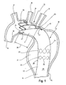
- Fig. 1 10 shows a stent which is anchored with its proximal end 11 in the aortic arch 12 and with its distal end 14 in the descending aorta 15.
- Fig. 1 Before the stent 10 is described in more detail, the first in Fig. 1 also schematically illustrated Aortensystem be explained.
- the ascending branch 16 (ascending aorta) of the aorta is above the in Fig. 1 not shown aortic root (sinus aortae) connected to the left ventricle of the heart, also not shown.
- the aorta ascendens 16 is connected via the aortic arch 12 with the descending aorta 15.
- arterial head vessels exit namely the arterial trunk truncus brachiocephalicus 17, the common carotid artery 18 and the subclavian artery 19.
- the stent 10 has a hollow cylindrical body 22 which extends through in Fig. 1 schematically indicated rings 23 of meandering supports 24 is formed, which are connected by prosthesis material 25 with each other.
- the prosthesis material 25 in a known manner a textile material or a film and is attached to the supports 24 by sewing, gluing or melting.
- the stent 10 has a wedge-shaped, to the proximal end 11 expanding, free jacket portion 27 which is spanned between a proximally last ring 28, a proximally penultimate ring 29 and a connecting support 31, which the last ring 28 with the penultimate ring 29 connects.
- This jacket region 27, which is essentially free of prosthesis material 25, makes it possible for blood brought in from the aorta ascendens 16 to reach the common carotid artery 18 and the subclavian artery 19. Outside the free jacket region 27, however, prosthesis material 25 is located between the last ring 28 and the penultimate ring 29, so that the stent 10 with its proximal end snugly fits against the aortic inner wall indicated at 30. In this way, blood is prevented from passing between the stent 10 and the aortic inner wall 30 into the area of the aneurysm 21 succeeded, possibly expanding it further and finally leading to a rupture.
- the structural design of the stent 10 from Fig. 1 is in the schematic side view of Fig. 2 shown in more detail, wherein for reasons of clarity, the prosthesis material 25 in Fig. 2 was omitted.
- the last ring 28, the penultimate ring 29 and further rings 23 are arranged in the longitudinal direction 32 one behind the other, of which only one is shown.
- Each of these rings 23, 28, 29 has a plurality of proximal pointed arches 33 and distal pointed arches 34, which are connected to one another by means of support sections 35 running obliquely to the longitudinal direction 32.
- the rings 23, 28 and 29 consisting of meandering circumferential supports 24 are formed.
- both the supports 24 and the connecting support 31 consist of a wire-shaped, elastic material.
- the proximal pointed arcs 33 of the last ring 28 have to the proximal pointed arcs 33 of the penultimate ring 29 a distance indicated at 36, which is greater than the distance 37 between the proximal arcs 33 of the penultimate ring 29 and the proximal arcs 33 of the pre-penultimate ring 23rd In this way, the stent 10 is more flexible and movable at its proximal end 11 than in the direction of its distal end 14.
- proximal pointed arcs 33 of the last ring 28 to the distal pointed arches 34 of the penultimate ring 29 a Distance 38 on, which is greater than in Fig. 1 indicated distance 39 between the exit of the subclavian artery 19 and the exit of the common carotid artery 18 from the aortic arch 12.
- the proximally last ring 28 can brace proximal of the common carotid artery at the aortic inner wall 30, while the penultimate ring 29 distally to the artery subclavian sinistra and there can push the prosthesis material 25 on the entire circumference against the aortic inner wall 30.
- the V-shaped connecting post 31, which connects the last ring 28 and the penultimate ring 29, has a distal ogive 41 and two legs 42 adjoining the ogive 41 which widen in a V-shape to the distal end 11 of the stent 10 ,
- the legs 42 are with their proximal ends 43 in abutment with support portions 35 of the last ring 28. With their distal ends 44, the legs 42 in abutment with corresponding support portions 35 of the penultimate ring 29.
- the connection between the support portions 35 and the respective ends 43rd , 44 of the legs 42 via pressing sleeves 45 which close the meandering supports 24, for example.
- the ring 23 to its Z-shaped course.
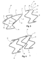
- Fig. 3 are the last ring 28 and the penultimate ring 29 shown immediately after production, so even before the connection with each other.
- the last ring 28 is formed beginning at its free end 49 by multiple Z-shaped bending of the corresponding wire material, so that the proximal and distal pointed arches 33 and 34 form.
- the wire material is continued distally and bent over the distal ogive 41 and returned to the support portion 35 where the wire is cut to give the second free end 50 of the one-piece structure containing both the last ring 28 and also represents the connection support 31.
- the penultimate ring 29 has correspondingly two free ends 51 and 52, which lie on both sides of the gap 48.
- the last ring 28 and the penultimate ring 29 forms, together with the connecting support 31, a fixing structure which is provided at the proximal end 11 of the stent 10.
- a fixation structure With this fixation structure, the aortic inner wall opposite to and proximal to the exit of the subclavian artery can now also be used as a fixation and sealing surface, without closing this outlet. If the new stent in the for implanted area, it is now no longer necessary to carry out a stressful service intervention.
- proximal pointed arcs 33 of the last ring 28 are widened outwards or bent outwards relative to the distal pointed arches 34, which is shown in FIG Fig. 2 can be seen above.
- the pointed arches 33 of the aortic inner wall 30 adapt and at the same time create a pressure on the aortic inner wall 30 by the elasticity of the wire material, which ensures the fixation and positioning as well as the sealing effect of the vascular endoprosthesis.
- Fig. 1 It can also be seen that the last ring 28 can be bent forward, as a result of which the legs 42 of the connecting support 31 spread outward and bear tightly against the aortic inner wall 30. This is still aided by the pressure exerted by the aortic inner wall on the last ring 28, which also spreads the legs 42 of the connecting support 31 under pressure to the outside. In this way, the prosthesis material fastened there is pressed outwards against the aortic inner wall 30 and thus forms a seal of the blood stream against the volume of the aneurysm 21.
- the wedge-shaped area 27, which remains free of the prosthesis material 25, provides the corresponding supply of the subclavian artery 19 and the common carotid artery 18.
- the marker 46 is a distal marker disposed distally to the distal ogive 41 of the connection support 31.
- the marker 47 is a proximal marker which is fastened to the jacket 26 distally to a support section of the last ring 28.
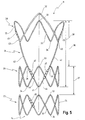
- FIG. 5 A further embodiment of the stent according to the invention is shown in a schematic side view in FIG Fig. 5 shown here, with here - as in Fig. 2 -
- the prosthesis material 25 has been omitted.
- Fig. 5 to 9a have been given the same reference numerals as used to designate the same elements of the stents Fig. 2 used.
- Fig. 5 It can be seen that also in this embodiment in the longitudinal direction 32 of the last ring 28, the penultimate ring 29 and other rings 23 are arranged one behind the other, of which only one is shown. It can further be seen that the last ring 28 has a proximal ogive 33 - and thereby also a distal ogive 34 - less than the penultimate ring 29 and as the ring 23. In this embodiment, there is therefore no need for this embodiment Fig. 2 the distal pointed arch 39 (see Fig. 2 ).
- FIG. 6 a further embodiment of the stent according to the invention is shown, this embodiment compared to the embodiment of Fig. 2 additional connecting posts 61 and 62 has.
- the connecting supports 61 and 62 are each provided with a proximal end 63 with a support portion 35 of the last ring 28 and with its distal end 64 each having a support portion 35 of the penultimate ring 29 in FIG Plant brought.
- a kind of flank reinforcement for the stent is represented by the additional connection supports 61 and 62.
- Fig. 7a are the last ring 28 and the penultimate ring 29 immediately after production, so even before the connection with each other, shown.
- Fig. 7a is - as in Fig. 3 -
- the additional connecting posts 61 and 62 are brought with its proximal end 63 with a support portion 35 of the last ring 28 in abutment, which is indicated by the arrows 65, and the distal ends 64 each with a support portion 35 of the penultimate ring 29, which by the Arrows 66 is indicated.
- FIG. 8 Yet another embodiment of the stent according to the invention is shown, wherein here as in Fig. 6 also two additional connecting posts 71 and 72 are provided, but which intersect at a point 77.
- Fig. 9b It is shown that the two rings 28 and 29 are brought together, the ends of the connecting posts 71 and 72 being connected to the respective supporting sections 35 of the last ring 28 and the penultimate ring 29, respectively, by attaching press sleeves 68.
Landscapes
- Health & Medical Sciences (AREA)
- Heart & Thoracic Surgery (AREA)
- Life Sciences & Earth Sciences (AREA)
- Cardiology (AREA)
- Oral & Maxillofacial Surgery (AREA)
- Transplantation (AREA)
- Engineering & Computer Science (AREA)
- Pulmonology (AREA)
- Biomedical Technology (AREA)
- Vascular Medicine (AREA)
- Gastroenterology & Hepatology (AREA)
- Animal Behavior & Ethology (AREA)
- General Health & Medical Sciences (AREA)
- Public Health (AREA)
- Veterinary Medicine (AREA)
- Prostheses (AREA)
- Media Introduction/Drainage Providing Device (AREA)
Description
- Die vorliegende Erfindung betrifft einen Stent zur Implantation in ein Blutgefäß, insbesondere im Bereich des Aortenbogens, mit in seiner Längsrichtung hintereinander angeordneten Ringen aus mäanderförmig umlaufenden Stützen und einem an den Ringen befestigten und diese verbindenden Prothesenmaterial, das einen hohlzylindrischen Körper mit umfänglich im Wesentlichen geschlossenen Mantel bildet.
- Ein derartiger Stent, allerdings nicht zur Implantation in den Aortenbogen, ist aus dem Stand der Technik bekannt.
- Diese auch als endovaskuläre Stents bezeichneten Gefäßstents werden zur Behandlung von Aneurysmen in Arterien implantiert. Unter einem Aneurysma versteht man eine Ausweitung oder Aussackung eines arteriellen Blutgefäßes infolge angeborener oder erworbener Wandveränderungen. Die Aussackung kann dabei die Gefäßwand als Ganzes erfassen oder es kann bei einem sog. falschen Aneurysma Blut aus dem Lumen des Gefäßes zwischen die Gefäßwandschichten treten und diese auseinander scheren. Die Nichtbehandlung eines Aneurysma kann im fortgeschrittenen Stadium zu einer Ruptur der Arterie führen, woraufhin der Patient innerlich verbluten kann.
- Aneurysmen treten zwar häufig im Bereich der Baucharterie (Aorta abdominalis) oder Brustarterie (Aorta thoracica) auf, ein Aneurysma kann aber auch im Bereich des aufsteigenden oder absteigenden Astes der Aorta (Aorta ascendens und Aorta descendens) auftreten. Der aufsteigende Ast der Aorta ist unmittelbar mit dem Herzen verbunden. Ausgehend von der Aortenwurzel (Sinus aortae) verläuft der aufsteigende Ast in leicht gekrümmter Form vom Herzen weg nach oben und geht dort in den Aortenbogen (Arcus aortae) über. Im Bereich des Aortenbogens zweigen die Kopfgefäße ab, u.a. die linke und die rechte Halsschlagader. Der Aortenbogen weist einen Kurvenverlauf von etwa 180° mit einem sehr engen Radius auf und verbindet den aufsteigenden Ast der Aorta mit dem absteigenden Ast.
- Die
WO 99/43378 A - Die
EP-A-1 075 825 offenbart eine verzweigte intraaortale Prothese, die in die Bauchaorta eines menschlichen Körpers implantiert wird, um ein Aneurysma an der Aortengabelung zu behandeln. Die Prothese weist eine Struktur mit einem Hauptstamm auf, der sich in zwei Schenkel von gleicher Länge teilt, sowie eine Umhüllung, die die Schenkel vollständig und den Hauptstamm teilweise umgibt. Die Prothese kann ferner röntgendichte Marker aufweisen, die in einem V-förmigen Muster in der netzförmigen Struktur des Stents angebracht sind. - Die
WO 97/09945 - Aus der
DE 100 65 824 A1 , die den nächstliegende Stand der Technik gegenüber dem Gegenstand des Anspruchs 1 bildet, ist ein Stent zur Implantation in den aufsteigenden Ast der Aorta bekannt. Der bekannte Stent weist einen hohlen, in Längsrichtung für den Durchgang von Blut offenen, hohlzylindrischen Körper mit einer Wand auf, die durch eine Maschenstruktur gebildet ist. Der Körper des bekannten Stents ist der anatomischen Form der Aortenwurzel angepasst und sich konkav erweiternd ausgebildet. An seinem dem Herzen zugewandten proximalen Ende sind an dem Stent in Umfangsrichtung verteilt schmale Fixierelemente angeordnet. An seinem in den Aortenbogen hineinreichenden distalen Ende ist der Körper des bekannten Stents sozusagen schräg abgeschnitten, so dass der Stent auf seinem Umfangsbereich, der im implantierten Zustand von den Kopfgefäßen weggelegen ist, eine größere Längenausdehnung aufweist als an dem gegenüberliegenden Umfangbereich. Auf diese Weise wird vermieden, dass die vom Aortenbogen abzweigenden Kopfgefäße durch den Stent abgedeckt werden. - Der bekannte Stent hat sich als im Bereich der Aorta ascendens gut einsetzbar erwiesen, auf Grund der völlig anders gelagerten anatomischen Verhältnisse im Bereich der Aorta descendens kann jedoch ein derart ausgebildeter Stent nicht verwendet werden, um Aneurysmen im Bereich der Aorta descendens zu behandeln.
- Bei derartigen thorakalen Aortenaneurysmen, die sich ggf. bis in den Aortenbogen, also bis zur linken Schlüsselbeinarterie (A. subclavia sinistra) ausdehnen, besteht nämlich das Problem, dass für die Stents nicht genügend proximale Fixierungs- und Dichtungsfläche vorhanden ist. Mit anderen Worten, der bekannte Stent kann im Aortenbogen gegenüber und proximal des Abganges der A. subclavia sinistra nicht hinreichend fixiert werden.
- In einem solchen Fall sind deshalb vor der endoluminalen Implantation einer Gefäßendoprothese, also eines entsprechenden Stents, chirurgische Eingriffe erforderlich. Dabei wird vor der Implantation des Stents eine gefäßchirurgische Verbindung zwischen der proximal von der A. subclavia sinistra vom Aortenbogen abgehenden A. carotis communis und der A. subclavia sinistra geschaffen, so dass die Schlüsselbeinarterie sozusagen über die A. carotis communis versorgt wird. Der Abgang der Schlüsselbeinarterie vom Aortenbogen kann dann problemlos von einer Gefäßendoprothese überdeckt und durch diese verschlossen werden, um für eine ausreichende Fixierungs- und Dichtungsfläche an der Aorteninnenwand zu sorgen.
- Derartige gefäßchirurgische Eingriffe sind sehr zeitaufwendig, zudem muss der Patient an eine Herz-Lungen-Maschine angeschlossen und die Körpertemperatur des Patienten stark heruntergekühlt werden. Aus diesem Grund liegt die Mortalitätsrate bei derartigen Eingriffen sehr hoch.
- Ein weiterer Nachteil ist darin zu sehen, dass eine Notversorgung eines Patienten mit thorakalem Aortenaneurysma durch Einführen eines Stents auf minimal-invasivem Wege bisher quasi nicht möglich ist, da eine hinreichend sichere Fixierung des proximalen Endes des Stents Probleme bereitet.
- Vor diesem Hintergrund liegt der vorliegenden Erfindung die Aufgabe zugrunde, einen Stent der eingangs genannten Art zu schaffen, der mit seinem proximalen Ende im Bereich des Aortenbogens platziert werden kann.
- Bei dem eingangs genannten Stent wird diese Aufgabe erfindungsgemäß dadurch gelöst, dass nur zwischen dem letzten und dem vorletzten Ring am proximalen Ende des Stents zumindest eine V-förmige Verbindungsstütze mit zwei Schenkeln, die sich V-förmig zum distalen Ende des Stents erweitern, vorgesehen ist, wobei die V-förmige Verbindungsstütze die beiden Ringe miteinander verbindet, und dass die Ringe im proximalen Bereich lediglich über Prothesenmaterial miteinander verbunden sind.
- Die der Erfindung zugrundeliegende Aufgabe wird auf diese Weise vollkommen gelöst.
- Die Erfinder der vorliegenden Anmeldung haben nämlich erkannt, dass auch Stents mit einem Mantel aus Prothesenmaterial zur Implantation in die A. descencens geeignet sind, wenn nur zwischen dem letzten und dem vorletzten Ring eine Verbindungsstütze vorgesehen, die diese beiden Ringe miteinander verbindet. Bei dem zur Implantation in die A. ascendens geeigneten Stent gemäß
DE 100 65 824 ist das im Aortenbogen liegende distale Ende des Stents abgeschrägt und ggf. offenmaschig, um eine Versorgung der Kopfarterien zu gewährleisten. Ein derartiger Maschenstent ist zur Behandlung von Aneurysmen im Bereich der Aorta descendens nicht geeignet, wobei auch eine reine Abschrägung am im Aortenbogen liegenden proximalen Ende des Stents zwar die Versorgung der abgehenden Arterien ermöglicht, nicht jedoch eine hinreichende Fixierung. Die Verbindungsstütze ermöglicht es jetzt dagegen, zwischen dem letzten und dem vorletzten Ring bspw. einen Teil der Mantelfläche auszusparen oder den Mantel mit Löchern zu versehen, so dass die Versorgung der abgehenden Kopfarterien gesichert ist. Andererseits sorgen sowohl der letzte Ring als auch die Verbindungsstützen dafür, dass das proximale Ende des neuen Stents sicher im Aortenbogen fixiert wird. - Dabei ist es bevorzugt, wenn zwischen dem letzten und dem vorletzten Ring im Bereich der Verbindungsstütze ein im Wesentlichen von Prothesenmaterial freier Mantelbereich aufgespannt ist, und wobei vorzugsweise der im Wesentlichen vom Prothesenmaterial freie Mantelbereich sich zum proximalen Ende des Stents keilförmig aufweitet.
- Hier ist von Vorteil, dass zum einen nicht der gesamte Mantelbereich zwischen dem letzten und dem vorletzten Ring ohne Prothesenmaterial ausgebildet ist. Dadurch ist es möglich, an der von den Abgängen der Kopfarterien abgelegenen Innenwand des Aortenbogens Prothesenmaterial und damit einen Mantelbereich vorzusehen, der nicht nur zur Abstützung, sondern auch als Dichtungsfläche verwendet wird. Durch die V-förmige Ausbildung der Verbindungsstütze lässt sich der sich zum proximalen Ende des Stents keilförmig aufweitende, von Prothesenmaterial freie Mantelbereich besonders einfach realisieren. Der Mantel ist im Bereich des keilförmigen Mantelbereiches entfernt, wobei die sich so ergebenden Kanten des Prothesenmaterials an den V-förmigen Streben der Verbindungsstütze befestigt werden.
- Während im distalen Bereich des neuen Stents die einzelnen Ringe miteinander lediglich über den Mantel, also das Prothesenmaterial, verbunden sind, erfolgt die Verbindung zwischen dem letzten und dem vorletzten Ring zum einen ebenfalls über den Mantel, andererseits aber auch über die Verbindungsstütze. Die Verbindungsstütze sorgt dafür, dass trotz des teilweise entfernten Mantels der letzte Ring am proximalen Ende sicher mit dem restlichen hohlzylindrischen Körper des Stents verbunden ist.
- Allgemein ist es bevorzugt, wenn die Stützen einen Z-förmigen Verlauf mit abwechselnd zum proximalen und zum distalen Ende des Stents weisenden Spitzbögen aufweisen, die durch schräg zur Längsrichtung verlaufende Stützabschnitte miteinander verbunden sind.
- Auf diese Weise wird eine Stentstruktur geschaffen, die einen hinreichenden radialen Druck ausübt, um sich in den proximal und distal vom Aneurysma liegenden Gefäßbereichen zu verankern, wobei andererseits der Stent dem Druck durch das durch ihn hindurchfließende Blut standhalten kann.
- Dabei ist es bevorzugt, wenn die proximalen Spitzbögen des letzten Ringes zu den proximalen Spitzbögen des vorletzten Ringes einen Abstand aufweisen, der größer ist als der Abstand zwischen den proximalen Spitzbögen des vorletzten Ringes und den proximalen Spitzbögen des vorvorletzten Ringes.
- Mit anderen Worten, der letzte Ring weist einen größeren Abstand zum vorletzten Ring auf als die anderen Ringe im Stent untereinander.
- Dies hat den Vorteil, dass sich der Stent an seinem proximalen Ende leichter der Krümmung im Aortenbogen anpassen kann. Dies wird zwar zum einen bereits durch den im Wesentlichen von Prothesenmaterial freien Mantelbereich ermöglicht, durch den größeren Abstand zwischen den Ringen am proximalen Ende wird hier die Steifigkeit jedoch stärker durch das verbleibende Prothesenmaterial bestimmt als im sonstigen Bereich des Stents, was eine bessere Biegsamkeit ermöglicht.
- Weiter ist es bevorzugt, wenn die proximalen Spitzbögen des letzten Ringes zu den distalen Spitzbögen des vorletzten Ringes einen Abstand aufweisen, der größer ist als der Abstand zwischen dem Abgang der A. subclavia sinistra und dem Abgang der A. carotis communis vom Aortenbogen.
- Bei dieser Maßnahme ist von Vorteil, dass die proximalen Spitzbögen des letzten Ringes sich proximal von der A. carotis communis an die Innenwand des Aortenbogens anlegen können, während die distalen Spitzbögen des vorletzten Ringes sich distal von der A. subclavia sinistra innen an die Aortenwand anlegen. Damit wird zum einen für eine sichere Verankerung des proximalen Endes des neuen Stents im Aortenbogen gesorgt, wobei gleichzeitig verhindert wird, dass im Bereich der Abgänge von A. carotis communis und A. subclavia sinistra ein zu starker Druck auf die Aorteninnenwand ausgeübt wird. Ferner ermöglicht es diese Konstruktion, den im Wesentlichen von Prothesenmaterial freien Mantelbereich so zu wählen, dass die Abgänge von A. carotis communis und A. subclavia sinistra nicht von Prothesenmaterial bedeckt werden.
- Allgemein ist es bevorzugt, wenn ein zum distalen Ende des Stents weisender Spitzbogen des vorletzten Ringes mit einem Spitzbogen einer Verbindungsstütze in Anlage ist, wobei vorzugsweise der zum distalen Ende des Stents weisende Spitzbogen des vorletzten Ringes zumindest teilweise durch den Spitzbogen der Verbindungsstütze gebildet ist.
- Hier ist von Vorteil, dass der Z-förmige Verlauf des vorletzten Ringes durch die Verbindungsstütze nicht verändert wird, die Verbindungsstütze passt sich vielmehr in die übliche Struktur des Ringes ein. Dabei kann der distale Spitzbogen des vorletzten Ringes teilweise weggelassen werden, wobei die so entstehende Lücke durch den Spitzbogen der Verbindungsstütze ausgefüllt ist.
- Weiter ist es bevorzugt, wenn die Verbindungsstütze zwei Schenkel aufweist, die an ihrem proximalen Ende jeweils mit einem Stützabschnitt des letzten Ringes in Anlage sind.
- Hier ist von Vorteil, dass auch der Z-förmige Verlauf des letzten Ringes durch die Verbindung mit der Verbindungsstütze nicht verändert werden muss.
- Dabei ist es weiter bevorzugt, wenn die Verbindungsstütze zwei Schenkel aufweist, die an ihrem distalen Ende jeweils mit einem Stützabschnitt des vorletzten Ringes in Anlage sind.
- Wie bereits erwähnt, hat diese Maßnahme konstruktive Vorteile, der Z-förmige Verlauf des letzten und vorletzten Ringes wird nicht gestört.
- Ein weiterer Vorteil liegt darin, dass durch diese Struktur ein Druck auf den letzten Ring dazu führt, dass sich die V-förmige Verbindungsstütze nach außen aufspreizt, so dass das dort befestigte Prothesenmaterial nach außen an die Aorteninnenwand gedrückt wird und so eine Abdichtung des Blutstromes gegen das Aneurysmavolumen bildet. Der nicht von Prothesenmaterial bedeckte Bereich der Stütze des proximal letzten Ringes sorgt dabei also für eine Verbiegung des von Prothesenmaterial bedeckten proximalen Prothesenendes entlang der torusförmigen Aorteninnenwand und gleichzeitig für ein Aufspreizen des keilförmigen ungedeckten Bereiches gegenüber den supraaortalen Gefäßabgängen sowie für das Aufdrücken der Schenkel der Verbindungsstütze zur Abdichtung des Blutstromes gegen das Aneurysmavolumen.
- Bei den oben stehenden Ausführungsformen des erfindungsgemäßen Stents kann dabei die Anzahl der Spitzbögen des letzten Rings gleich derjenigen des vorletzten Rings sein.
- In einer anderen Ausführungsform ist es bevorzugt, wenn die Anzahl der Spitzbögen des letzten Ringes geringer ist als die Anzahl der Spitzbögen des vorletzten Ringes.
- Der Stent, bzw. die Verteilung der Spitzbögen im letzten Ring des Stents, kann dabei bspw. derart ausgebildet sein, dass in dem im Wesentlichen von Prothesenmaterial freien Mantelbereich, der im Bereich der Verbindungsstütze aufgespannt ist, kein freier distaler Spitzbogen vorliegt. Dadurch kann sich der Stent bei dieser Ausführungsform beim Zurückziehen in die distale Richtung nicht in den Gefäßwänden verhaken.
- Diese Ausführungsform kann ferner bspw. derart ausgebildet sein, dass im letzten Ring an derjenigen Stelle kein distaler Spitzbogen ausgebildet ist, die dem zum distalen Ende des Stents weisenden Spitzbogen des vorletzten Rings, der zumindest teilweise durch den Spitzbogen der Verbindungsstütze gebildet ist, entspricht bzw. gegenüberliegt.
- In wiederum einer anderen Ausführungsform ist bevorzugt, wenn zumindest zwei weitere Verbindungsstützen vorgesehen sind, die jeweils mit ihrem proximalen Ende mit einem Stützabschnitt des letzten Ringes und jeweils mit ihrem distalen Ende mit einem Stützabschnitt des vorletzten Ringes in Anlage sind.
- Dabei ist in einer weiteren Ausführungsform ferner bevorzugt, wenn sich die zwei weiteren Verbindungsstützen in einem Punkt kreuzen.
- Durch die weiteren Verbindungsstützen dieser Ausführungsformen kann die Flankenstabilität und die Flankendichtigkeit vorteilhaft erhöht werden.
- Diese Ausführungsformen haben ferner zum Vorteil, dass die Stabilität des Stents insbesondere im distalen Bereich unterstützt wird, wodurch ebenfalls Verhakungsproblematiken der Spitzbögen beim Zurückziehen des Stents in distale Richtung vermieden werden können.
- Weiter ist es bevorzugt, wenn der letzte Ring und die Verbindungsstütze einstückig miteinander ausgebildet sind.
- Diese Maßnahme ist konstruktiv von Vorteil, es ist lediglich erforderlich, einen üblichen Z-förmigen Ring zu biegen und dann eines der freien Enden in Richtung des distalen Bereiches zu verlängern, dort umzulenken und zu dem letzten Ring zurückzuführen.
- Allgemein ist es bevorzugt, wenn der jeweilige Stützabschnitt des letzten oder vorletzten Ringes und ein mit diesem in Anlage befindlicher Abschnitt der Verbindungsstütze durch eine Presshülse miteinander verbunden sind.
- Diese Maßnahme ist zum einen konstruktiv von Vorteil, denn die aneinander anliegenden Drahtbereiche werden auf diese Weise miteinander verkrimpt. Diese Maßnahme ist aber auch unter Sicherheitsaspekten von Vorteil, denn auf diese Weise werden die freien Enden sowohl des vorletzten als auch des letzten Ringes durch die Krimphülsen abgedeckt, so dass Verletzungen der Aorteninnenwand vermieden werden.
- Weiter ist es bevorzugt, wenn die zum proximalen Ende des Stents weisenden Spitzbögen des letzten Ringes gegenüber dessen zum distalen Ende des Stents weisenden Spitzbögen nach außen gebogen sind.
- Bei dieser Maßnahme ist von Vorteil, dass sich die proximalen Spitzbögen der Innenwand des Aortenbogens anpassen, die in guter Näherung als Innenfläche eines Torus-Segmentes angesehen werden kann. Gleichzeitig erzeugen die nach außen gebogenen Spitzbögen durch die Elastizität des Drahtmaterials einen Druck auf die Aortenwand, der die Fixierung und Positionierung sowie die Dichtwirkung der Gefäßendoprothese, also des Stents, - sicherstellt.
- Allgemein ist es bevorzugt, wenn die Stützen und die Verbindungsstütze aus einem drahtförmigen, elastischen Material bestehen.
- Diese Maßnahme ist an sich bekannt, sie sorgt dafür, dass der Stent zur Einführung in das Lumen der Aorta zunächst zusammengedrückt werden kann, so dass sich sein Außendurchmesser verringert. Nach dem Freisetzen des Stents expandiert sich dieser und verankert sich so in dem entsprechenden Blutgefäß.
- Allgemein ist es bevorzugt, wenn distal zu einem distalen Spitzbogen der Verbindungsstütze an dem Mantel ein distaler Marker angebracht ist, wobei ferner vorzugsweise distal zu einem Stützabschnitt des letzen Ringes an dem Mantel ein proximaler Marker angeordnet ist, wobei die Marker vorzugsweise Röntgenmarker sind.
- Bei dieser Maßnahme ist von Vorteil, dass eine Positionierungshilfe geschaffen wird, durch die während der Implantation und zur Überprüfung der Lage des im Wesentlichen von Prothesenmaterial freien Mantelbereiches gegenüber den supraaortalen Abgängen nach der Implantation die aktuelle Lage des Stents verfolgt werden kann.
- Allgemein ist es bevorzugt, wenn das Prothesenmaterial aus textilem Material oder aus Folie besteht, wobei weiter vorzugsweise das Prothesenmaterial an den Stützen und der Verbindungsstütze durch Nähen, Kleben oder Einschmelzen befestigt ist.
- Diese Maßnahmen sind aus dem Stand der Technik bekannt, sie ermöglichen eine schnelle und preiswerte, aber dennoch sichere Fertigung des neuen Stents.
- Weitere Vorteile und Merkmale ergeben sich aus der nachfolgenden Beschreibung und der beigefügten Zeichnung.
- Es versteht sich, dass die vorstehend genannten und die nachstehend noch zu erläuternden Merkmale nicht nur in der jeweils angegebenen Kombination, sondern auch in anderen Kombinationen oder in Alleinstellung verwendbar sind, ohne den Rahmen der vorliegenden Erfindung zu verlassen.
- Ein Ausführungsbeispiel der Erfindung ist in der Zeichnung dargestellt und wird in Bezug auf diese nachstehend näher beschrieben. Es zeigen:
- Fig. 1
- eine schematische Darstellung einer Ausführungsform eines in den absteigenden Ast der Aorta implantierten endovaskulären Stents;
- Fig. 2
- die Stützstruktur für den Stent aus
Fig. 1 , jedoch ohne den umgebenden Mantel; - Fig. 3
- den proximal letzten und vorletzten Ring des Stents aus
Fig. 2 , noch ohne Verbindung untereinander; - Fig. 4
- die beiden Ringe aus
Fig. 3 , jetzt jedoch durch Presshülsen miteinander verbunden; - Fig. 5
- eine weitere Ausführungsform des erfindungsgemäßen Stents ohne umgebenden Mantel;
- Fig. 6
- noch eine weitere Ausführungsform des erfindungsgemäßen Stents mit zusätzlichen Verbindungsstützen, ebenfalls ohne umgebenden Mantel;
- Fig. 7a
- den proximal letzten und vorletzten Ring des Stents aus
Fig. 6 , mit den anzubringenden Verbindungsstützen, jedoch noch ohne die Verbindung untereinander; - Fig. 7b
- die beiden Ringe aus
Fig. 7a , jetzt durch Presshülsen untereinander verbunden; - Fig. 8
- wiederum eine weitere Ausführungsform des erfindungsgemäßen Stents mit sich kreuzenden zusätzlichen Verbindungsstützen, ohne umgebenden Mantel;
- Fig. 9a
- den proximal letzten und vorletzten Ring des Stents aus
Fig. 8 , mit den anzubringenden, sich kreuzenden Verbindungsstützen, noch ohne Verbindung untereinander; und - Fig. 9b
- die beiden Ringe aus
Fig. 9a , jetzt durch Presshülsen miteinander verbunden. - In
Fig. 1 ist mit 10 ein Stent gezeigt, der mit seinem proximalen Ende 11 in dem Aortenbogen 12 und mit seinem distalen Ende 14 in der Aorta descendens 15 verankert ist. - Bevor der Stent 10 näher beschrieben wird, soll zunächst das in
Fig. 1 ebenfalls schematisch dargestellte Aortensystem erläutert werden. - Der aufsteigende Ast 16 (A. ascendens) der Aorta ist über die in
Fig. 1 nicht gezeigte Aortenwurzel (Sinus aortae) mit der ebenfalls nicht dargestellten linken Kammer des Herzens verbunden. Die Aorta ascendens 16 ist über den Aortenbogen 12 mit der Aorta descendens 15 verbunden. Im Bereich des Aortenbogens 12 gehen arterielle Kopfgefäße ab, nämlich der Arterienstamm Truncus brachiocephalicus 17, die Arteria carotis communis 18 und die Arteria subclavia sinistra 19. - In der Aorta descendens 15 ist bei 21 ein Aneurysma dargestellt, das durch den Stent 10 sozusagen überbrückt ist. Der aus der Aorta ascendens 16 kommende Blutstrom gelangt über den Aortenbogen 12 in das proximale Ende 11 des Stents 10 und verlässt diesen am distalen Ende 14. Zu diesem Zweck weist der Stent 10 einen hohlzylindrischen Körper 22 auf, der durch in
Fig. 1 schematisch angedeutete Ringe 23 aus mäanderförmigen Stützen 24 gebildet ist, die durch Prothesenmaterial 25 miteinander verbunden sind. Das Prothesenmaterial 25 in bekannter Weise ein textiles Material oder eine Folie und ist durch Nähen, Kleben oder Einschmelzen an den Stützen 24 befestigt. - Auf diese Weise wird der Durchgang durch den Stent offen gehalten, so dass sich der hohlzylindrische Körper 22 bildet.
- An seinem proximalen Ende 11 weist der Stent 10 einen keilförmigen, sich zum proximalen Ende 11 aufweitenden, freien Mantelbereich 27 auf, der zwischen einem proximal letzten Ring 28, einem proximal vorletzten Ring 29 sowie einer Verbindungsstütze 31 aufgespannt ist, die den letzten Ring 28 mit dem vorletzten Ring 29 verbindet.
- Dieser im Wesentlichen von Prothesenmaterial 25 freie Mantelbereich 27 ermöglicht es, dass aus der Aorta ascendens 16 herangeführtes Blut in die Arteria carotis communis 18 sowie die Arteria subclavia sinistra 19 gelangen kann. Außerhalb des freien Mantelbereiches 27 befindet sich jedoch zwischen dem letzten Ring 28 und dem vorletzten Ring 29 Prothesenmaterial 25, so dass sich der Stent 10 mit seinem proximalen Ende hier dicht an die bei 30 angedeutete Aorteninnenwand anschmiegt. Auf diese Weise wird verhindert, dass Blut zwischen den Stent 10 und der Aorteninnenwand 30 hindurch in den Bereich des Aneurysmas 21 gelang, dieses ggf. weiter aufdehnt und schließlich zu einer Ruptur führt.
- Der konstruktive Aufbau des Stents 10 aus
Fig. 1 ist in der schematischen Seitenansicht derFig. 2 näher dargestellt, wobei aus Gründen der Übersichtlichkeit das Prothesenmaterial 25 inFig. 2 weggelassen wurde. - Zunächst ist zu erkennen, dass in Längsrichtung 32 hintereinander der letzte Ring 28, der vorletzte Ring 29 sowie weitere Ringe 23 angeordnet sind, von denen lediglich einer dargestellt ist. Jeder dieser Ringe 23, 28, 29 weist mehrere proximale Spitzbögen 33 sowie distale Spitzbögen 34 auf, die durch schräg zur Längsrichtung 32 verlaufende Stützabschnitte 35 miteinander verbunden sind. Auf diese Weise bilden sich die aus mäanderförmig umlaufenden Stützen 24 bestehenden Ringe 23, 28 und 29. Es sei noch erwähnt, dass sowohl die Stützen 24 als auch die Verbindungsstütze 31 aus einem drahtförmigen, elastischen Material bestehen.
- Die proximalen Spitzbögen 33 des letzten Ringes 28 weisen zu den proximalen Spitzbögen 33 des vorletzten Ringes 29 einen bei 36 angedeuteten Abstand auf, der größer ist als der Abstand 37 zwischen den proximalen Spitzbögen 33 des vorletzten Ringes 29 und den proximalen Spitzbögen 33 des vorvorletzten Ringes 23. Auf diese Weise ist der Stent 10 an seinem proximalen Ende 11 biegsamer und beweglicher als in Richtung seines distalen Endes 14.
- Ferner weisen die proximalen Spitzbögen 33 des letzten Ringes 28 zu den distalen Spitzbögen 34 des vorletzten Ringes 29 einen Abstand 38 auf, der größer ist als der in
Fig. 1 angedeutete Abstand 39 zwischen dem Abgang der Arteria subclavia sinistra 19 und dem Abgang der Arteria carotis communis 18 vom Aortenbogen 12. Auf diese Weise kann sich der proximal letzte Ring 28 proximal von der Arteria carotis communis an der Aorteninnenwand 30 verspannen, während sich der vorletzte Ring 29 distal zu der Arteria subclavia sinistra verspannen und dort das Prothesenmaterial 25 auf dem gesamten Umfang gegen die Aorteninnenwand 30 drücken kann. - Die V-förmige Verbindungsstütze 31, die den letzten Ring 28 und den vorletzten Ring 29 miteinander verbindet, weist einen distalen Spitzbogen 41 sowie zwei sich an den Spitzbogen 41 anschließende Schenkel 42 auf, die sich V-förmig zum distalen Ende 11 des Stents 10 erweitern. Die Schenkel 42 sind mit ihren proximalen Enden 43 in Anlage mit Stützabschnitten 35 des letzten Ringes 28. Mit ihren distalen Enden 44 sind die Schenkel 42 in Anlage mit entsprechenden Stützabschnitten 35 des vorletzten Ringes 29. Die Verbindung zwischen den Stützabschnitten 35 und den jeweiligen Enden 43, 44 der Schenkel 42 erfolgt über Presshülsen 45, die auch die mäanderförmigen Stützen 24 bspw. des Ringes 23 zu ihrem Z-förmigen Verlauf schließen.
- In
Fig. 3 sind der letzte Ring 28 sowie der vorletzte Ring 29 unmittelbar nach der Fertigung, also noch vor der Verbindung miteinander dargestellt. - Es ist in
Fig. 3 links zu erkennen, dass der letzte Ring 28 und die Verbindungsstütze 31 einstückig miteinander ausgebildet sind. Ferner ist inFig. 3 rechts zu erkennen, dass dem vorletzten Ring 29 sozusagen ein distaler Spitzbogen 34 fehlt, was durch eine bei 48 angedeutete Lücke dargestellt ist. Diese Lücke wird jetzt durch den distalen Spitzbogen 41 der Verbindungsstütze 31 gefüllt. - Der letzte Ring 28 wird beginnend bei seinem freien Ende 49 durch mehrfaches Z-förmiges Umbiegen des entsprechenden Drahtmaterials gebildet, so dass sich die proximalen und distalen Spitzbögen 33 und 34 bilden. Wenn der Ring 28 geschlossen ist, wird das Drahtmaterial distal weitergeführt und am distalen Spitzbogen 41 umgebogen und zurückgeführt zum Stützabschnitt 35, wo der Draht abgeschnitten wird, so dass sich das zweite freie Ende 50 des einstückigen Gebildes ergibt, das sowohl den letzten Ring 28 als auch die Verbindungsstütze 31 darstellt. Der vorletzte Ring 29 weist entsprechend zwei freie Enden 51 und 52 auf, die beiderseits der Lücke 48 liegen.
- Der letzte Ring 28 sowie der vorletzte Ring 29 werden jetzt so zusammengeführt, wie dies in
Fig. 4 dargestellt ist, wobei an den freien Enden 49 bis 52 jeweils eine Presshülse 45 aufgeschoben wird, die zum einen die Schenkel 42 mit den entsprechenden Stützabschnitten 35 verbindet und zum anderen die freien Enden 49 bis 52 verdeckt, so dass eine Verletzung der Aorteninnenwand vermieden wird. - Der letzte Ring 28 sowie der vorletzte Ring 29 bildet zusammen mit der Verbindungsstütze 31 eine Fixierungsstruktur, die am proximalen Ende 11 des Stents 10 vorgesehen ist. Mit dieser Fixierungsstruktur kann nun auch die Aorteninnenwand gegenüber und proximal des Abganges der Arteria subclavia sinistra als Fixierungs- und Dichtungsfläche genutzt werden, ohne dass dieser Abgang verschlossen wird. Wenn der neue Stent in dem dafür vorgesehenen Bereich implantiert wird, ist es jetzt nicht mehr erforderlich, vorher einen belastenden Serviceeingriff durchzuführen.
- Es sei noch erwähnt, dass die proximalen Spitzbögen 33 des letzten Ringes 28 gegenüber den distalen Spitzbögen 34 nach außen aufgeweitet bzw. nach außen gebogen sind, was in
Fig. 2 oben zu erkennen ist. Dadurch passen sich die Spitzbögen 33 der Aorteninnenwand 30 an und erzeugen gleichzeitig durch die Elastizität des Drahtmaterials einen Druck auf die Aorteninnenwand 30, der die Fixierung und Positionierung sowie die Dichtwirkung der Gefäßendoprothese sicherstellt. - In
Fig. 1 ist ferner zu erkennen, dass der letzte Ring 28 nach vorne gebogen werden kann, wodurch sich die Schenkel 42 der Verbindungsstütze 31 nach außen spreizen und eng an die Aorteninnenwand 30 anlegen. Dies wird noch unterstützt durch den Druck, den die Aorteninnenwand auf den letzten Ring 28 ausübt, der unter Druck ebenfalls die Schenkel 42 der Verbindungsstütze 31 nach außen spreizt. Auf diese Weise wird das dort befestigte Prothesenmaterial nach außen an die Aorteninnenwand 30 gedrückt und bildet so eine Abdichtung des Blutstromes gegen das Volumen des Aneurysma 21. - Der keilförmig vom Prothesenmaterial 25 frei bleibende Bereich 27 sorgt für die entsprechende Versorgung von Arteria subclavia sinistra 19 und Arteria carotis communis 18.
- Als Positionierungshilfe während der Implantation und zur Überprüfung der Lage des ungedeckten Prothesenbereiches, also des freien Mantelbereiches 27 gegenüber den supraaortalen Abgängen 19 und 18 nach der Implantation dienen zwei Röntgenmarker 46 und 47, die in
Fig. 1 zu sehen sind. Der Marker 46 ist ein distaler Marker, der distral zu dem distalen Spitzbogen 41 der Verbindungsstütze 31 angeordnet ist. Der Marker 47 ist dagegen ein proximaler Marker, der distal zu einem Stützabschnitt des letzten Ringes 28 an dem Mantel 26 befestigt ist. - Eine weitere Ausführungsform des erfindungsgemäßen Stents ist in einer schematischen Seitenansicht in
Fig. 5 dargestellt, wobei auch hier - wie inFig. 2 - aus Gründen der Übersichtlichkeit das Prothesenmaterial 25 weggelassen wurde. In denFig. 5 bis 9a wurden zur Bezeichnung der gleichen Elemente der Stents die gleichen Bezugszeichen wie inFig. 2 verwendet. - In
Fig. 5 ist zu erkennen, dass auch bei dieser Ausführungsform in Längsrichtung 32 hintereinander der letzte Ring 28, der vorletzte Ring 29 sowie weitere Ringe 23 angeordnet sind, von denen lediglich einer dargestellt ist. Es ist ferner zu erkennen, dass der letzte Ring 28 einen proximalen Spitzbogen 33 - und dadurch auch einen distalen Spitzbogen 34 - weniger aufweist als der vorletzte Ring 29 und als der Ring 23. Bei dieser Ausführungsform fehlt demnach im Vergleich zuFig. 2 der distale Spitzbogen 39 (sieheFig. 2 ). - In
Fig. 6 ist eine weitere Ausführungsform des erfindungsgemäßen Stents dargestellt, wobei diese Ausführungsform im Vergleich zur Ausführungsform ausFig. 2 zusätzliche Verbindungsstützen 61 und 62 aufweist. Die Verbindungsstützen 61 und 62 sind mit ihrem proximalen Ende 63 jeweils mit einem Stützabschnitt 35 des letzten Ringes 28 und mit ihrem distalen Ende 64 jeweils mit einem Stützabschnitt 35 des vorletzten Ringes 29 in Anlage gebracht. In derFig. 6 ist zu erkennen, dass dadurch die zusätzlichen Verbindungsstützen 61 und 62 eine Art Flankenverstärkung für den Stent darstellen. - In
Fig. 7a sind der letzte Ring 28 sowie der vorletzte Ring 29 unmittelbar nach der Fertigung, also noch vor der Verbindung miteinander, dargestellt. InFig. 7a ist - wie inFig. 3 - zu erkennen, dass der letzte Ring 28 und die Verbindungsstütze 31 einstückig miteinander ausgebildet sind. Die zusätzlichen Verbindungsstützen 61 und 62 werden mit ihrem proximalen Ende 63 mit einem Stützabschnitt 35 des letzten Ringes 28 in Anlage gebracht, was durch die Pfeile 65 angedeutet ist, sowie die distalen Enden 64 jeweils mit einem Stützabschnitt 35 des vorletzten Ringes 29, was durch die Pfeile 66 angedeutet ist. - In
Fig. 7b ist zu erkennen, dass die beiden Ringe 28 und 29 zusammengeführt sind, wobei die Enden jeweils über Presshülsen 68 mit den entsprechenden Stützabschnitten 35 verbunden sind, so dass Verletzungen der Aorteninnenwand vermieden werden. - In
Fig. 8 ist noch eine weitere Ausführungsform des erfindungsgemäßen Stents dargestellt, wobei hier wie inFig. 6 ebenfalls zwei zusätzliche Verbindungsstützen 71 und 72 vorgesehen sind, die sich aber in einem Punkt 77 kreuzen. - Ähnlich wie in
Fig. 7a ist inFig. 9a zu erkennen, dass die sich kreuzenden Verbindungsstützen 71 und 72 jeweils über ihr proximales Ende 73 mit einem Stützabschnitt 35 des letzten Ringes 28 in Anlage gebracht werden, was durch die Pfeile 75 angedeutet ist, und mit ihrem distalen Ende 74 mit einem Stützabschnitt 35 des vorletzten Ringes 29, was mit den Pfeilen 76 angedeutet ist. - In
Fig. 9b ist gezeigt, zu erkennen, dass die beiden Ringe 28 und 29 zusammengeführt sind, wobei die Enden der Verbindungsstützen 71 und 72 durch Anbringen von Presshülsen 68 mit den jeweiligen Stützabschnitten 35 des letzten Ringes 28 bzw. des vorletzten Ringes 29 verbunden werden.
Claims (22)
- Stent zur Implantation in ein Blutgefäß (15), insbesondere im Bereich des Aortenbogens (12), mit in seiner Längsrichtung (32) hintereinander angeordneten Ringen (23, 28, 29) aus mäanderförmig umlaufenden Stützen (24) und einem an den Ringen (23, 28, 29) befestigten und diese verbindenden Prothesenmaterial (25), das einen hohlzylindrischer Körper mit umfänglich im Wesentlichen geschlossenen Mantel (21) bildet,
dadurch gekennzeichnet, dass nur zwischen dem letzten (28) und dem vorletzten (29) Ring am proximalen Ende (14) des Stents (10) zumindest eine V-förmige Verbindungsstütze (31) mit zwei Schenkeln (42), die sich V-förmig zum distalen Ende (11) des Stents (10) erweitern, vorgesehen ist, wobei die V-förmige Verbindungsstütze (31) den letzten (28) und den vorletzten (29) Ring miteinander verbindet, und dass die Ringe im distalen Bereich lediglich über das Prothesenmaterial (25) miteinander verbunden sind. - Stent nach Anspruch 1, dadurch gekennzeichnet, dass zwischen dem letzten und dem vorletzten Ring (28, 29) im Bereich der Verbindungsstütze (31) ein im Wesentlichen von Prothesenmaterial (25) freier Mantelbereich (27) aufgespannt ist.
- Stent nach Anspruch 1 oder 2, dadurch gekennzeichnet, dass der im Wesentlichen von Prothesenmaterial (25) freie Mantelbereich (27) sich zum proximalen Ende (11) des Stents (10) keilförmig aufweitet.
- Stent nach einem der Ansprüche 1 bis 3, dadurch gekennzeichnet, dass die Stützen (24) einen Z-förmigen Verlauf mit abwechselnd zum proximalen (11) und zum distalen (14) Ende des Stents (10) weisenden Spitzbögen (33, 34) aufweisen, die durch schräg zur Längsrichtung (32) verlaufende Stützabschnitte (35) miteinander verbunden sind.
- Stent nach Anspruch 4, dadurch gekennzeichnet, dass die proximalen Spitzbögen (33) des letzten Ringes (28) zu den proximalen Spitzbögen (33) des vorletzten Ringes (29) einen Abstand (36) aufweisen, der größer ist als der Abstand (37) zwischen den proximalen Spitzbögen (33) des vorletzten Ringes (29) und den proximalen Spitzbögen (33) des vorvorletzten Ringes (23).
- Stent nach Anspruch 4 oder 5, dadurch gekennzeichnet, dass die proximalen Spitzbögen (33) des letzten Ringes (28) zu den distalen Spitzbögen (34) des vorletzten Ringes (29) eines Abstand (38) aufweisen, der größer ist als der Abstand (38) zwischen dem Abgang der A. subclavia sinister (19) und dem Abgang der A. carotis communis (18) vom Aortenbogen (12).
- Stent nach einem der Ansprüche 4 bis 6, dadurch gekennzeichnet, dass ein zum distalen Ende (14) des Stents (10) weisender Spitzbogen (41) des vorletzten Ringes (29) mit einem Spitzbogen der Verbindungsstütze (31) in Anlage ist.
- Stent nach Anspruch 7, dadurch gekennzeichnet, dass der zum distalen Ende (14) des Stents (10) weisende Spitzbogen (41) des vorletzten Ringes (29) zumindest teilweise durch den Spitzbogen der Verbindungsstütze (31) gebildet ist.
- Stent nach einem der Ansprüche 4 bis 8, dadurch gekennzeichnet, dass die zwei Schenkel (42) der Verbindungsstütze (31) an ihrem proximalen Ende (43) jeweils mit einem Stützabschnitt (35) des letzten Ringes (28) in Anlage sind.
- Stent nach einem der Ansprüche 4 bis 9, dadurch gekennzeichnet, dass die zwei Schenkel (42) der Verbindungsstütze (31) an ihrem distalen Ende (44) jeweils mit einem Stützabschnitt (35) des vorletzten Ringes (29) in Anlage sind.
- Stent nach einem der Ansprüche 1 bis 10, dadurch gekennzeichnet, dass die Anzahl der Spitzbögen (33; 34) des letzten Ringes (28) geringer ist als die Anzahl der Spitzbögen (33, 34) des vorletzten Ringes (29)
- Stent nach einem der Ansprüche 4 bis 10, dadurch gekennzeichnet, dass zumindest zwei weitere Verbindungsstützen (61, 62; 71, 72) vorgesehen sind, die mit ihrem proximalen Ende (63) jeweils mit einem Stützabschnitt (35) des letzten Ringes (28) und mit ihrem distalen Ende (64) jeweils mit einem Stützabschnitt (35) des vorletzten Ringes (29) in Anlage sind.
- Stent nach Anspruch 12, dadurch gekennzeichnet, dass die Verbindungsstützen (71, 72) über ihr jeweils proximales Ende (73) und jeweils distales Ende (74) mit den Stützabschnitten (35) des letzten (28) und vorletzten (29) Ringes derart in Anlage sind, dass sich die Verbindungsstützen (71, 72) in einem Punkt (77) kreuzen.
- Stent nach einem der Ansprüche 1 bis 13, dadurch gekennzeichnet, dass der letzte Ring (28) und die Verbindungsstütze (31) einstückig miteinander ausgebildet sind.
- Stent nach einem der Ansprüche 4 bis 14, dadurch gekennzeichnet, dass der jeweilige Stützabschnitt (35) des letzten (28) oder vorletzten (29) Ringes und ein mit diesem in Anlage befindlicher Abschnitt der zumindest einen Verbindungsstütze (31; 61; 62; 71, 72) durch eine Presshülse (45; 68) miteinander verbunden sind.
- Stent nach einem der Ansprüche 4 bis 15, dadurch gekennzeichnet, dass die zum proximalen Ende (11) des Stents (10) weisenden Spitzbögen (33) des letzten Ringes (28) gegenüber dessen zum distalen Ende (14) des Stents (10) weisenden Spitzbögen (34) nach außen gebogen sind.
- Stent nach einem der Ansprüche 1 bis 16, dadurch gekennzeichnet, dass die Stützen (24) und die zumindest eine Verbindungsstütze (31; 61, 62; 71; 72) aus einem drahtförmigen, elastischen Material bestehen.
- Stent nach einem der Ansprüche 1 bis 17, dadurch gekennzeichnet, dass distal zu einem distalen Spitzbogen (41) der Verbindungsstütze (31) an dem Mantel (26) ein distaler Marker (46) angeordnet ist.
- Stent nach einem der Ansprüche 4 bis 18, dadurch gekennzeichnet, dass distal zu einem Stützabschnitt (35) des letzten Ringes (28) an dem Mantel (26) ein proximaler Marker (47) angeordnet ist.
- Stent nach Anspruch 18 oder 19, dadurch gekennzeichnet, dass der Marker (46, 47) ein Röntgenmarker ist.
- Stent nach einem der Ansprüche 1 bis 20, dadurch gekennzeichnet, dass das Prothesenmaterial (25) aus textilem Material oder aus Folie besteht.
- Stent nach einem der Ansprüche 1 bis 21, dadurch gekennzeichnet, dass das Prothesenmaterial (25) an den Stützen (14) und der zumindest einen Verbindungsstütze (31; 61, 62; 71, 72) durch Nähen, Kleben oder Einschmelzen befestigt ist.
Applications Claiming Priority (2)
| Application Number | Priority Date | Filing Date | Title |
|---|---|---|---|
| DE10337739A DE10337739B4 (de) | 2003-08-12 | 2003-08-12 | Stent zur Implantation in ein Blutgefäß, insbesondere im Bereich des Aortenbogens |
| PCT/EP2004/008916 WO2005013854A1 (de) | 2003-08-12 | 2004-08-10 | Stent zur implantation in ein blutgefäss, insbesondere im bereich des aortenbogens |
Publications (2)
| Publication Number | Publication Date |
|---|---|
| EP1653883A1 EP1653883A1 (de) | 2006-05-10 |
| EP1653883B1 true EP1653883B1 (de) | 2015-01-21 |
Family
ID=34129588
Family Applications (1)
| Application Number | Title | Priority Date | Filing Date |
|---|---|---|---|
| EP04763937.2A Expired - Lifetime EP1653883B1 (de) | 2003-08-12 | 2004-08-10 | Stent zur implantation in ein blutgefäss, insbesondere im bereich des aortenbogens |
Country Status (5)
| Country | Link |
|---|---|
| US (1) | US8668729B2 (de) |
| EP (1) | EP1653883B1 (de) |
| DE (1) | DE10337739B4 (de) |
| ES (1) | ES2532371T3 (de) |
| WO (1) | WO2005013854A1 (de) |
Families Citing this family (34)
| Publication number | Priority date | Publication date | Assignee | Title |
|---|---|---|---|---|
| US20040267349A1 (en) | 2003-06-27 | 2004-12-30 | Kobi Richter | Amorphous metal alloy medical devices |
| US8382821B2 (en) | 1998-12-03 | 2013-02-26 | Medinol Ltd. | Helical hybrid stent |
| US9155639B2 (en) * | 2009-04-22 | 2015-10-13 | Medinol Ltd. | Helical hybrid stent |
| US20060161241A1 (en) * | 2005-01-14 | 2006-07-20 | Denise Barbut | Methods and devices for treating aortic atheroma |
| DE602006019753D1 (de) * | 2005-09-01 | 2011-03-03 | Medtronic Vascular Inc | Verfahren und gerät zur behandlung von aneurysmen der a. thoracica |
| US8070795B2 (en) * | 2006-08-02 | 2011-12-06 | Mani, Inc. | Stent with a joining portion and a non-joining portion for joining a stent main wire and a strut |
| US20080109055A1 (en) * | 2006-11-02 | 2008-05-08 | Sage Medical Technologies, Inc. | Implant for aortic dissection and methods of use |
| GB2470041B (en) * | 2009-05-06 | 2011-05-18 | Cook William Europ | Stent graft |
| DE102012100754A1 (de) | 2012-01-31 | 2013-08-01 | Jotec Gmbh | Modularer Stentgraft |
| GB2499377B (en) * | 2012-02-01 | 2014-04-30 | Cook Medical Technologies Llc | Implantable medical device |
| US8998975B2 (en) | 2012-11-12 | 2015-04-07 | Medtronic Vascular, Inc. | Helical stent with orthogonal end and method of forming stent |
| DE102012111223A1 (de) | 2012-11-21 | 2014-05-22 | Jotec Gmbh | Gefäßimplantat mit asymmetrischen Stentfedern |
| US10034784B2 (en) | 2013-04-17 | 2018-07-31 | Gilbert H. L. Tang | Heart valve and endovascular graft components and method for delivery |
| GB2516928A (en) * | 2013-08-07 | 2015-02-11 | Vascutek Ltd | Prosthesis Device |
| CN103598929B (zh) * | 2013-11-28 | 2016-04-20 | 先健科技(深圳)有限公司 | 胸主动脉覆膜支架 |
| DE102014114747A1 (de) | 2014-10-10 | 2016-04-14 | Jotec Gmbh | Gefäßprothesen-System |
| DE102014116012A1 (de) | 2014-11-04 | 2016-05-04 | Jotec Gmbh | Modulares Stentgraft-System |
| KR102501552B1 (ko) | 2015-01-11 | 2023-03-21 | 어씨러스 메디컬, 엘엘씨 | 외과적 대동맥 수복용 하이브리드 장치 |
| EP3632376B1 (de) * | 2015-01-12 | 2024-03-06 | Endospan Ltd. | Selbstkrümmendes stenttransplantat |
| US10004617B2 (en) | 2015-10-20 | 2018-06-26 | Cook Medical Technologies Llc | Woven stent device and manufacturing method |
| DE102015123000A1 (de) | 2015-12-30 | 2017-07-06 | Jotec Gmbh | Selbstexpandierende Gefäßprothese |
| DE102016102008A1 (de) | 2016-02-04 | 2017-08-10 | Jotec Gmbh | Gefäßprothese mit Seitenästen |
| CN108261253B (zh) * | 2016-12-31 | 2021-06-15 | 先健科技(深圳)有限公司 | 覆膜支架 |
| CN106726038B (zh) * | 2017-01-23 | 2018-05-25 | 中国人民解放军第二军医大学 | 一种升主动脉腔内隔绝移植装置 |
| CN109561961B (zh) | 2017-04-07 | 2021-02-23 | 上海甲悦医疗器械有限公司 | 一种人工瓣膜及人工瓣膜植入方法 |
| DE102017111964A1 (de) | 2017-05-31 | 2018-12-06 | Jotec Gmbh | Stentgraft mit Taschen |
| US9848906B1 (en) | 2017-06-20 | 2017-12-26 | Joe Michael Eskridge | Stent retriever having an expandable fragment guard |
| CN209107691U (zh) * | 2017-07-03 | 2019-07-16 | 深圳市科奕顿生物医疗科技有限公司 | 一种自膨式管腔支架 |
| DE102017120819A1 (de) | 2017-09-08 | 2019-03-14 | Jotec Gmbh | Intraluminales Gefäßprothesensystem |
| EP3510976B1 (de) | 2018-01-11 | 2020-09-09 | Cook Medical Technologies LLC | Drahtstent mit widerhaken |
| JP7609796B2 (ja) | 2019-03-20 | 2025-01-07 | インキュベート メディカル テクノロジーズ、 エルエルシー | 大動脈解離インプラント |
| US12478488B2 (en) | 2020-02-19 | 2025-11-25 | Medinol Ltd. | Helical stent with enhanced crimping |
| CN116919683B (zh) * | 2023-09-15 | 2023-12-08 | 北京华脉泰科医疗器械股份有限公司 | 分支血管内假体和血管内假体输送装置 |
| DE102024108793A1 (de) * | 2024-03-27 | 2025-10-02 | MEDIRA GmbH | Herzklappenprothese zur Behandlung von Trikuspidalklappeninsuffizienz |
Citations (1)
| Publication number | Priority date | Publication date | Assignee | Title |
|---|---|---|---|---|
| WO1997009945A1 (en) * | 1995-09-11 | 1997-03-20 | William Cook Europe A/S | An expandable endovascular stent |
Family Cites Families (20)
| Publication number | Priority date | Publication date | Assignee | Title |
|---|---|---|---|---|
| US5843167A (en) * | 1993-04-22 | 1998-12-01 | C. R. Bard, Inc. | Method and apparatus for recapture of hooked endoprosthesis |
| EP0657147B1 (de) * | 1993-11-04 | 1999-08-04 | C.R. Bard, Inc. | Ortsfeste Gefässprothese |
| US5800521A (en) * | 1994-11-09 | 1998-09-01 | Endotex Interventional Systems, Inc. | Prosthetic graft and method for aneurysm repair |
| US5683449A (en) * | 1995-02-24 | 1997-11-04 | Marcade; Jean Paul | Modular bifurcated intraluminal grafts and methods for delivering and assembling same |
| JP3390449B2 (ja) * | 1995-06-01 | 2003-03-24 | ミードックス メディカルズ インコーポレイテッド | 移植可能な管腔内補綴具 |
| FR2737404B1 (fr) * | 1995-08-03 | 1997-09-19 | Braun Celsa Sa | Prothese implantable dans un conduit humain ou animal, telle qu'un elargisseur de paroi, ou une prothese pour anevrisme |
| US5591195A (en) * | 1995-10-30 | 1997-01-07 | Taheri; Syde | Apparatus and method for engrafting a blood vessel |
| US6030414A (en) * | 1997-11-13 | 2000-02-29 | Taheri; Syde A. | Variable stent and method for treatment of arterial disease |
| AUPP083597A0 (en) * | 1997-12-10 | 1998-01-08 | William A Cook Australia Pty Ltd | Endoluminal aortic stents |
| US6395018B1 (en) * | 1998-02-09 | 2002-05-28 | Wilfrido R. Castaneda | Endovascular graft and process for bridging a defect in a main vessel near one of more branch vessels |
| US6280467B1 (en) * | 1998-02-26 | 2001-08-28 | World Medical Manufacturing Corporation | Delivery system for deployment and endovascular assembly of a multi-stage stented graft |
| WO1999062431A1 (en) * | 1998-06-02 | 1999-12-09 | Cook Incorporated | Multiple-sided intraluminal medical device |
| US6071307A (en) * | 1998-09-30 | 2000-06-06 | Baxter International Inc. | Endoluminal grafts having continuously curvilinear wireforms |
| FR2797389B1 (fr) * | 1999-08-09 | 2001-11-30 | Novatech Inc | Prothese aortique bifurquee |
| AU3803801A (en) * | 2000-02-03 | 2001-08-14 | Cook Inc | Implantable vascular device |
| US6319278B1 (en) * | 2000-03-03 | 2001-11-20 | Stephen F. Quinn | Low profile device for the treatment of vascular abnormalities |
| DE10065824B4 (de) | 2000-12-28 | 2018-10-31 | Jotec Gmbh | Endovaskulärer Stent zur Implantation in den aufsteigenden Ast der Aorta |
| DK1245202T3 (da) * | 2001-03-27 | 2004-08-30 | Cook William Europ | Aortagrafindretning |
| US7147661B2 (en) * | 2001-12-20 | 2006-12-12 | Boston Scientific Santa Rosa Corp. | Radially expandable stent |
| EP1336393A3 (de) * | 2002-02-14 | 2003-11-19 | John S. Geis | Stentprothese, Einführungsvorrichtung sowie Einführungsset für eine Stentprothese |
-
2003
- 2003-08-12 DE DE10337739A patent/DE10337739B4/de not_active Expired - Lifetime
-
2004
- 2004-08-10 WO PCT/EP2004/008916 patent/WO2005013854A1/de not_active Ceased
- 2004-08-10 ES ES04763937.2T patent/ES2532371T3/es not_active Expired - Lifetime
- 2004-08-10 EP EP04763937.2A patent/EP1653883B1/de not_active Expired - Lifetime
-
2006
- 2006-02-10 US US11/352,590 patent/US8668729B2/en active Active
Patent Citations (1)
| Publication number | Priority date | Publication date | Assignee | Title |
|---|---|---|---|---|
| WO1997009945A1 (en) * | 1995-09-11 | 1997-03-20 | William Cook Europe A/S | An expandable endovascular stent |
Also Published As
| Publication number | Publication date |
|---|---|
| US8668729B2 (en) | 2014-03-11 |
| DE10337739B4 (de) | 2009-11-26 |
| ES2532371T3 (es) | 2015-03-26 |
| WO2005013854A1 (de) | 2005-02-17 |
| EP1653883A1 (de) | 2006-05-10 |
| US20060195177A1 (en) | 2006-08-31 |
| DE10337739A1 (de) | 2005-03-10 |
Similar Documents
| Publication | Publication Date | Title |
|---|---|---|
| DE10337739B4 (de) | Stent zur Implantation in ein Blutgefäß, insbesondere im Bereich des Aortenbogens | |
| DE69518435T3 (de) | System zur Herstellung eines abzweigenden Transplantats | |
| DE60023769T2 (de) | Ballonkatheter | |
| DE69826444T2 (de) | Endovaskuläres implantat zum ausbessern eines aneurysmas der abdominalaorta | |
| DE10334868B4 (de) | Implantierbare Einrichtung als Organklappenersatz, dessen Herstellungsverfahren sowie Grundkörper und Membranelement dafür | |
| EP1648342B1 (de) | Geflochtener stent zur implantation in ein blutgefäss | |
| EP3897454B1 (de) | Vorrichtung zum zuführen und setzen eines implantats in ein blutgefäss | |
| DE102012101103B3 (de) | Stentgraft mit Fixierelementen und Einführsystem | |
| DE69729475T2 (de) | Vorrichtung zum einführen und freisetzen einer endoprothese | |
| EP3203931B1 (de) | Gefässprothesen-system | |
| EP3060177B1 (de) | Gefässimplantat mit bereichen unterschiedlicher radialkraft | |
| EP2809267B1 (de) | INTRALUMINALE GEFÄßPROTHESE | |
| EP3215055B1 (de) | Modulares stentgraft-system | |
| EP3678589B1 (de) | Intraluminales gefässprothesensystem | |
| DE10065824B4 (de) | Endovaskulärer Stent zur Implantation in den aufsteigenden Ast der Aorta | |
| WO2013113704A1 (de) | Modularer stentgraft | |
| DE102016102008A1 (de) | Gefäßprothese mit Seitenästen | |
| EP3630009B1 (de) | Stentgraft mit taschen | |
| EP2846731B1 (de) | Intraluminale gefässprothese mit in-situ-fenestrierung | |
| DE102007060497A1 (de) | Implantierbare Gefäßstütze | |
| EP4013349A1 (de) | Gefaessprothese | |
| EP1306063A1 (de) | Stent |
Legal Events
| Date | Code | Title | Description |
|---|---|---|---|
| PUAI | Public reference made under article 153(3) epc to a published international application that has entered the european phase |
Free format text: ORIGINAL CODE: 0009012 |
|
| 17P | Request for examination filed |
Effective date: 20051217 |
|
| AK | Designated contracting states |
Kind code of ref document: A1 Designated state(s): DE ES FR GB IT |
|
| RIN1 | Information on inventor provided before grant (corrected) |
Inventor name: BRAUN, MICHAEL Inventor name: MUELLER, HARDY Inventor name: LESMEISTER, RAINER Inventor name: GEIS, JOHN Inventor name: KAUFMANN, RALF |
|
| DAX | Request for extension of the european patent (deleted) | ||
| RBV | Designated contracting states (corrected) |
Designated state(s): DE ES FR GB IT |
|
| 17Q | First examination report despatched |
Effective date: 20080211 |
|
| REG | Reference to a national code |
Ref country code: DE Ref legal event code: R079 Ref document number: 502004014817 Country of ref document: DE Free format text: PREVIOUS MAIN CLASS: A61F0002060000 Ipc: A61F0002070000 |
|
| GRAP | Despatch of communication of intention to grant a patent |
Free format text: ORIGINAL CODE: EPIDOSNIGR1 |
|
| RIC1 | Information provided on ipc code assigned before grant |
Ipc: A61F 2/07 20130101AFI20140905BHEP |
|
| INTG | Intention to grant announced |
Effective date: 20140925 |
|
| GRAS | Grant fee paid |
Free format text: ORIGINAL CODE: EPIDOSNIGR3 |
|
| GRAA | (expected) grant |
Free format text: ORIGINAL CODE: 0009210 |
|
| AK | Designated contracting states |
Kind code of ref document: B1 Designated state(s): DE ES FR GB IT |
|
| REG | Reference to a national code |
Ref country code: GB Ref legal event code: FG4D Free format text: NOT ENGLISH |
|
| REG | Reference to a national code |
Ref country code: DE Ref legal event code: R096 Ref document number: 502004014817 Country of ref document: DE Effective date: 20150226 |
|
| REG | Reference to a national code |
Ref country code: ES Ref legal event code: FG2A Ref document number: 2532371 Country of ref document: ES Kind code of ref document: T3 Effective date: 20150326 |
|
| REG | Reference to a national code |
Ref country code: DE Ref legal event code: R097 Ref document number: 502004014817 Country of ref document: DE |
|
| PLBE | No opposition filed within time limit |
Free format text: ORIGINAL CODE: 0009261 |
|
| STAA | Information on the status of an ep patent application or granted ep patent |
Free format text: STATUS: NO OPPOSITION FILED WITHIN TIME LIMIT |
|
| 26N | No opposition filed |
Effective date: 20151022 |
|
| REG | Reference to a national code |
Ref country code: FR Ref legal event code: PLFP Year of fee payment: 13 |
|
| REG | Reference to a national code |
Ref country code: FR Ref legal event code: PLFP Year of fee payment: 14 |
|
| REG | Reference to a national code |
Ref country code: FR Ref legal event code: PLFP Year of fee payment: 15 |
|
| P01 | Opt-out of the competence of the unified patent court (upc) registered |
Effective date: 20230526 |
|
| PGFP | Annual fee paid to national office [announced via postgrant information from national office to epo] |
Ref country code: IT Payment date: 20230825 Year of fee payment: 20 Ref country code: GB Payment date: 20230824 Year of fee payment: 20 |
|
| PGFP | Annual fee paid to national office [announced via postgrant information from national office to epo] |
Ref country code: FR Payment date: 20230822 Year of fee payment: 20 Ref country code: DE Payment date: 20230926 Year of fee payment: 20 |
|
| PGFP | Annual fee paid to national office [announced via postgrant information from national office to epo] |
Ref country code: ES Payment date: 20231027 Year of fee payment: 20 |
|
| REG | Reference to a national code |
Ref country code: DE Ref legal event code: R071 Ref document number: 502004014817 Country of ref document: DE |
|
| REG | Reference to a national code |
Ref country code: ES Ref legal event code: FD2A Effective date: 20240829 |
|
| REG | Reference to a national code |
Ref country code: GB Ref legal event code: PE20 Expiry date: 20240809 |
|
| PG25 | Lapsed in a contracting state [announced via postgrant information from national office to epo] |
Ref country code: GB Free format text: LAPSE BECAUSE OF EXPIRATION OF PROTECTION Effective date: 20240809 |
|
| PG25 | Lapsed in a contracting state [announced via postgrant information from national office to epo] |
Ref country code: ES Free format text: LAPSE BECAUSE OF EXPIRATION OF PROTECTION Effective date: 20240811 |
|
| PG25 | Lapsed in a contracting state [announced via postgrant information from national office to epo] |
Ref country code: GB Free format text: LAPSE BECAUSE OF EXPIRATION OF PROTECTION Effective date: 20240809 Ref country code: ES Free format text: LAPSE BECAUSE OF EXPIRATION OF PROTECTION Effective date: 20240811 |