EP1653746A2 - Codage et décodage sans pertes de données entières - Google Patents
Codage et décodage sans pertes de données entières Download PDFInfo
- Publication number
- EP1653746A2 EP1653746A2 EP05109484A EP05109484A EP1653746A2 EP 1653746 A2 EP1653746 A2 EP 1653746A2 EP 05109484 A EP05109484 A EP 05109484A EP 05109484 A EP05109484 A EP 05109484A EP 1653746 A2 EP1653746 A2 EP 1653746A2
- Authority
- EP
- European Patent Office
- Prior art keywords
- parameter
- mode
- encoder
- adaptive
- run
- Prior art date
- Legal status (The legal status is an assumption and is not a legal conclusion. Google has not performed a legal analysis and makes no representation as to the accuracy of the status listed.)
- Withdrawn
Links
Images


Classifications
-
- H—ELECTRICITY
- H03—ELECTRONIC CIRCUITRY
- H03M—CODING; DECODING; CODE CONVERSION IN GENERAL
- H03M7/00—Conversion of a code where information is represented by a given sequence or number of digits to a code where the same, similar or subset of information is represented by a different sequence or number of digits
- H03M7/30—Compression; Expansion; Suppression of unnecessary data, e.g. redundancy reduction
-
- G—PHYSICS
- G06—COMPUTING; CALCULATING OR COUNTING
- G06F—ELECTRIC DIGITAL DATA PROCESSING
- G06F7/00—Methods or arrangements for processing data by operating upon the order or content of the data handled
-
- H—ELECTRICITY
- H04—ELECTRIC COMMUNICATION TECHNIQUE
- H04N—PICTORIAL COMMUNICATION, e.g. TELEVISION
- H04N19/00—Methods or arrangements for coding, decoding, compressing or decompressing digital video signals
- H04N19/10—Methods or arrangements for coding, decoding, compressing or decompressing digital video signals using adaptive coding
- H04N19/102—Methods or arrangements for coding, decoding, compressing or decompressing digital video signals using adaptive coding characterised by the element, parameter or selection affected or controlled by the adaptive coding
- H04N19/13—Adaptive entropy coding, e.g. adaptive variable length coding [AVLC] or context adaptive binary arithmetic coding [CABAC]
-
- H—ELECTRICITY
- H04—ELECTRIC COMMUNICATION TECHNIQUE
- H04N—PICTORIAL COMMUNICATION, e.g. TELEVISION
- H04N19/00—Methods or arrangements for coding, decoding, compressing or decompressing digital video signals
- H04N19/90—Methods or arrangements for coding, decoding, compressing or decompressing digital video signals using coding techniques not provided for in groups H04N19/10-H04N19/85, e.g. fractals
- H04N19/91—Entropy coding, e.g. variable length coding [VLC] or arithmetic coding
Definitions
- the present invention relates in general to the processing of digital data and more particularly to an improved method and system of lossless encoding and decoding of integer data using a novel backward-adaptive technique.
- Data compression is becoming increasingly important as the size of computer data (such as text, audio, video, image and program files) continues to grow.
- Data compression is a way of encoding digital data into an encoded representation that uses fewer bits than the original data. Representing the data in fewer bits means that the data occupies less storage space and requires less transmission bandwidth.
- data compression compresses a data by predicting the most frequently-occurring data and storing it in less space.
- data compression involves at least two different tasks: (1) defining a data model to predict the probabilities of the input data; and (2) using a coder to generate codes from those probabilities.
- some data compression techniques mathematically transform and quantize the data to achieve even greater compression.
- a compression technique may be lossless or lossy.
- a lossless compression technique is reversible such that the original data before encoding and the decompressed data after decoding are bit-for-bit identical.
- Lossy compression uses the fact there is much repetition in data that can be thrown away with much loss in quality. Lossy compression accepts the loss of some of the original data in order to achieve a higher compression.
- Lossless compression typically is used to compress text or binary data
- lossy compression typically is used for audio, image and video data.
- lossy compression techniques can sometimes use a lossless compression technique.
- two commonly-used kinds of compression (or coding) technique are transform coding and predictive coding.
- the original data is transformed and then quantized (rounded to nearest integers), or predicted based on (fixed or adaptive) signal models, and the prediction errors (differences between the original and predicted data) are then quantized.
- the data after quantization are in integer form. Once these integers are obtained, a lossless compression technique is used to encode the quantized values, in order to reduce the number of bits needed to represent the data.
- the set of these integer values usually has an associated probability distribution function (PDF).
- PDFs PDFs have a distribution such that if the data properties are well modeled by the predictor, in predictive coding, then the prediction error should be close to zero most of the time.
- FIG. 1 illustrates a typical probability distribution for these integer values; zero is the most likely value, and the probabilities of nonzero values decrease nearly exponentially fast as the magnitude increases.
- the data has a probability distribution shown in FIG. 1 because the data that is being encoded using the lossless compression technique is not the original data.
- FIG. 1 is the integer data resulting from quantizing transform coefficients or prediction errors.
- the problem is to find an efficient solution to encoding a vector x containing N integers.
- Each of the elements x ( n ), n 0, 1, ..., N -1, has a value according to a probability distribution similar to that in FIG. 1, so that the most probable value is zero, and values farther away from zero have fast decreasing probabilities.
- TSG two-sided geometric
- the parameter ⁇ controls the rate of decay in probability as
- ] 2 ⁇ 1 ⁇ ⁇ 2
- a good encoder should map a vector of N values of x into a bitstream containing not much more than N ⁇ H(x) bits, the theoretical minimum.
- the Laplacian distribution is a common model in media compression systems, for either prediction errors in predictive coders (like most lossless audio and image coders) or for quantized transform coefficients (like most lossy audio, image, and video coders).
- a simple but efficient encoder is the Golomb-Rice encoder.
- the new source u has a probability distribution that approximates that of a geometric source, for which Golomb codes are optimal, because they are Huffman codes for geometric sources, as long as the Golomb parameter is chosen appropriately.
- the main advantage of G/R codes over Huffman codes is that the binary codeword can be computed by a simple rule, for any input value. Thus, no tables need to be stored. This is particularly useful for modern processors, for which reading from a memory location that stores a table entry can take longer than executing several instructions. It is easy to see that the parameter m determines how many consecutive codeword have the same number of bits. That also indicates that computing the codeword involves computing u / m, where u is the input value.
- G/R codes are optimal for geometrically-distributed sources, they are not optimal for encoding symbols from a Laplacian/TSG source via the mapping in Equation 4. This is because for an input variable x with a TSG distribution, the variable u from Equation 4 has a probability distribution that is close to but not exactly geometric. In practice, the performance is close enough to optimal (e.g. with a rate that is typically less than 5% above the entropy), so G/R codes are quite popular.
- the optimal codes for TSG sources involve a set of four code variants, which are more complex to implement and improve compression by 5% or less in most cases. Therefore, in most cases G/R coders provide the best tradeoff between performance and simplicity.
- the probability distribution is represented by a single parameter, which is the rate of decay of the exponential. The faster the rate of decay, then the more likely is the value of zero. This means that in many cases zero is so likely that runs of zeros become very likely. In other words, if the probability distribution rate of decay is fast enough then encoding runs is a good idea. Encoding runs of zeros means that just a few bits are used to take care of many entries in the input data.
- Run length encoding is a simple form of data compression in which sequences of the same value repeated consecutively (or "runs") are stored as a single data value and the length of the run, rather than as the original run.
- Prediction errors are much more likely to be zero if the data matches the model used by the predictor in predictive coding, for example. It is possible, however, even with a good model, to every once in a while have a large value. This can occur when a boundary is reached, such as a pixel value goes from a background value to a foreground value. Every now and then big numbers can occur.
- RLGR Un-Length Golomb/Rice
- the first issue (estimation of the optimal Golomb/Rice parameter) is usually addressed by dividing the input vector into blocks of a predetermined length. For each block, the encoder makes two passes over the data. In the first pass, the average magnitude of input values is computed. For that, the parameter ⁇ can be estimated from Equation 2, and the corresponding optimal k can be determined. In a second pass, the encoder generates the bitstream for the block by first outputting the value of k in binary form, followed by the concatenated strings of Golomb/Rice codes for the data values within the block.
- This is the approach used in essentially all lossless compression systems that use Golomb/Rice codes, such as JPEG-LS for lossless image compression, SHORTEN for lossless audio compression, and others.
- the forward adaptation model is forward in the sense that the encoder looks at the data first before encoding, measures a statistical parameter (usually the average magnitude), and then encodes based on that parameter and puts the value of the parameter used to encode the data in a header, for use by the decoder. Instead of trying to code the data all at once, the data is broken up into small portions, or blocks. For each block, the statistics of that block are measured, a statistical parameter is measure for that portion of data that matches what is in the buffer, and the entropy coder is adjusted to that parameter. In the encoded file a header is inserted that indicates the value of the parameter being used to encode that block of data.
- the second issue in practice namely, encoding sources with very low entropy, is usually addressed using a blockwise adaptation or forward adaptation model, and if the average magnitude value of the input symbols in the block is small enough that the estimated entropy H(x) is less than 1, then the encoder uses Run-Length coding, instead of Golomb/Rice coding.
- One disadvantage is that the encoder needs to read each input block twice, such that two passes are performed on the data: a first time to compute the average magnitude to determine the Golomb/Rice parameter, and a second time to perform the actual encoding. This requires the encoder to perform additional work and adds complexity. In some applications encoding time is not an issue, but for digital cameras, for example, it can slow down the encoding process or increase the cost of random-access memory. In particular, the forward adaptation model must first look at the data and measure the statistics, find model parameters, and then encode. This is not an issue if the encoder runs on a personal computer having a great deal of processing power. However, if pictures taken with a cell phone, they are being encoded by the cell phone itself, where processing power is much more limited.
- the second and most important disadvantage involves the difficulty in choosing the block size. If the block size is too large, the statistics could change dramatically within the block. On the other hand, if the block size is too small, then the overhead of having to tell the decoder which parameter was used to encode that block of data becomes burdensome. For every block, the encoder must store what parameters values are being used to encode that block. At some point the overhead required to encode the small block is not worth the compression achieved. This is creates a trade-off. On the one hand, if a small block is used, the statistics of the block can be matched, however, measuring the statistics is difficult because there are few numbers, and the overhead of encoding is great.
- the block size is usually chosen to be between 128 and 2,048 samples, depending on the type of data to be encoded.
- One solution is to use a backward-adaptive technique in the encoder.
- backward adaptation encoding starts with the decoder and encoder agreeing on initial states is for each block.
- each parameter is initialized to a predetermined value, and then the encoding begins. Every time the encoder produces an output symbol, that symbol can be sent to the decoder immediately, because the decoder knows the parameter values used to encode it. After the encoder outputs a symbol, it then computes new values for the encoding parameters, depending on the symbol that was output, according to a predetermined adaptation rule. The decoder knows the parameter adaptation rule, and therefore it can also compute the new values for the encoding parameters.
- the encoding parameters are adjusted after every encoded symbol, and the encoder and decoder are always in sync, that is, the decoder tracks the changes in the encoding parameters. This means that the encoder does not need to send the decoder any overhead information in terms of what parameter values were used to encode the data.
- a lossless compression encoder and method provides efficient compression of integer data by switching between Run-Length encoding for encoding runs of zeros and Golomb/Rice encoding for encoding numbers after the run of zeros.
- an adaptive encoder and method that is capable of handling and encoding any input integer number that may appear after the run of zeros.
- an adaptive encoder and method that avoids the aforementioned problems with forward adaptation by using a backward-adaptive technique to provide fast tracking and efficient compression of the input data.
- the invention disclosed herein includes an adaptive Run-Length Golomb/Rice (RLGR) encoder and decoder (codec) and method for lossless encoding of integer data.
- the adaptive RLGR codec and method uses backward adaptation to provide fast tracking of changing statistics in the input data. Using backward adaptation, the adaptive RLGR codec and method quickly learns any changes in the statistics of the input data.
- the adaptive RLGR codec and method is capable of encoding any input integer value.
- the adaptive RLGR codec and method may be applied in a wide variety of compression applications, including multimedia compression systems such as audio, image and video encoders.
- the adaptive RLGR codec and method combines Run-Length encoding and Golomb/Rice (G/R) encoding in a novel way.
- the adaptive RLGR codec and method has a first mode, which is G/R encoding only (G/R only mode), and a second mode, which is G/R encoding plus Run-Length encoding (RLGR mode).
- the adaptive RLGR codec and method also uses a novel backward-adaptive technique that adjusts the encoding parameters after each encoded symbol.
- the encoding mode (G/R only mode or RLGR mode) is automatically determined from the parameter values. No probability tables or codeword tables are necessary, so the adaptive RLGR codec and method can fit within a small memory footprint.
- the adaptive RLGR codec and method thus is well-suited for modern processors, where memory access usually takes many more cycles than instruction fetching and execution. It is also well-suited for small devices with limited memory and limited processing power, because the adaptive RLGR codec and method does not need to buffer the input data in blocks, and does not need to process each data value twice.
- the adaptive RLGR codec and method uses simple but novel combination of coding rules, mapping strings of the input data to output codewords, depending on the encoding mode.
- the adaptive RLGR codec and method also uses a novel backward-adaptive technique having novel adaptation rules.
- Two parameters are used, namely, an encoder run parameter (s) and a Golomb/Rice (G/R) parameter (k).
- the encoding run parameter controls whether the adaptive RLGR codec and method uses Run-Length encoding (for s > 0) and, if so, then how Run-Length encoding is used.
- the adaptive RLGR codec and method is attractive for many practical applications.
- the adaptive RLGR method includes selecting between a first encoding mode that uses an entropy encoder other than a Run-Length encoder and a second encoding mode that uses the entropy encoder combined with the Run-Length encoder, and adapting the encoders of the first and second modes using a backward-adaptive technique.
- the entropy encoder is a Golomb/Rice encoder.
- the run r is define as an incomplete run and the codeword is 1 + bin( r,s ) + GR(u,k), where bin( r,s ) is the binary representation of the length of the incomplete run r in s bits, and GR(u,k) is the Golomb/Rice code for the value following the incomplete run r (using again the mapping from x to u).
- the adaptation rules of the backward-adaptive technique include rules for each of the parameters s and k.
- 0, then a scaled version of s, namely S, is increased by a first integer constant, A1. If
- > 0, then S is decreased by a second integer constant, B1. If s > 0 (RLGR mode), then if the run r is a complete run, then S is increased by a third integer constant, A 2. If the run r is an incomplete run, then s is decreased by a fourth integer constant, B2. The value of s to be used for generating the next codeword is then computed as s S / L, where L is a fixed parameter (the division by L is just a shift operator if L is chosen as a power of two.
- the adaptive RLGR method also includes a feature called "fractional adaptation". Fractional adaptation allows for a finer control of the rate of adaptation.
- a scaling parameter, L is defined, and the value of L is typically set to a power of two.
- the scaled parameter values S and K are incremented or decremented by integer constants, depending on the generated codeword.
- integer increments for S and K can be seen as fractional increments for s and k , which allow smoother control of the values of s and k , thus with better tracking of changes in the input statistics. If s and k were adjusted by integer increments after every encoded symbol, their values would fluctuate too much. Such noise in parameter values would lead to a decrease in the compression ratio (the ratio in the number of bits needed to store the input data in straight binary format to the number of bits needed to store the encoded bitstream).
- An adaptive RLGR codec includes modules for incorporating the adaptive RLGR method described above.
- An adaptive RLGR codec and method works by using decoding rules corresponding to the encoding rules above, and using the same parameter adaptation rules described above.
- the decoder After decoding a codeword from the input bitstream or file as described above, the decoder then computes the same adaptation rules as described for the encoder above. In this manner, the decoder will adjust the values of the parameters s and k in exactly the same way as the encoder does. Thus, the parameters will have the correct value for decoding the next bitstream (or file) codeword.
- the Run-Length Golomb/Rice (RLGR) encoder and method disclosed herein can be used in a wide variety of compression applications.
- Multimedia compression systems e.g. audio, image, and video codecs
- RLGR codec and method has been implemented in applications for compression of image, audio, terrain elevation, and geometric map data.
- the results of using the RLGR codec and method in these applications have been compression ratios that are comparable to the most sophisticated entropy coders, but in a simpler implementation.
- the RLGR codec and method disclosed herein is an improved technique for the lossless compression of integer data.
- Vectors containing integer values are mapped by the encoder into a bitstream, which later then can be reconstructed exactly by the decoder.
- the RLGR codec and method quickly learns and adapts to changes in the statistics of the input data.
- the RLGR codec and method may be applied in a wide variety of compression applications including multimedia compression systems such as audio, image, and video codecs,
- the RLGR codec and method combines Run-Length encoding and Golomb-Rice encoding in a novel way, and is characterized by a backward-adaptation strategy that adjusts the encoder parameters after each encoded symbol. Probability tables or codeword tables are unnecessary, which allows the RLGR codec and method to fit in a very small memory footprint.
- the RLGR codec and method thus is particularly well-suited for modern processors, where memory access takes usually many more cycles than instruction fetching and execution.
- One key advantage of the RLGR codec and method over previous kinds of entropy coders is that its backward-adaptation strategy quickly learns changes in the statistics of the data.
- the RLGR codec and method has exhibited better performance than other kinds of encoders, such as Huffman coders, block-adaptive Golomb/Rice encoders or context-adaptive arithmetic encoders.
- Another advantage of using a backward-adaptation strategy for the encoding parameters is that probability estimators are not needed.
- Still another advantage of the RLGR codec and method is that it performs adaptation after each encoded symbol, in a single pass over the data, thus producing better compression results and faster encoding than encoders that use blockwise or forward adaptation.
- FIGS. 2A & B are block diagrams illustrating an exemplary implementation of an adaptive Run-Length Golomb/Rice (RLGR) encoder and method disclosed herein.
- RLGR Run-Length Golomb/Rice
- FIG. 2A a block diagram for an encoder portion of the adaptive Run-Length RLGR codec and method is shown.
- FIG. 2B a block diagram for the decoder portion of the adaptive Run-Length RLGR codec and method is shown. It should be noted that FIGS. 2A & B are merely two of several ways in which the adaptive RLGR codec and method may implemented and used.
- the adaptive RLGR encoder 200 runs on a first computing device 210.
- the adaptive RLGR encoder 200 inputs and processes integer data 220.
- the adaptive RLGR encoder 200 encodes or maps the integer data 220 into an encoded bitstream 230.
- the integer data 220 typically contains vectors of integers such that the most probable value is zero and any nonzero values have probabilities that decrease as the values increase.
- This type of integer data typically has a probability distribution function (PDF) similar to that shown in FIG. 1.
- PDF probability distribution function
- a RLGR decoder 240 resides on a second computing device 250. It should be noted that although shown as separate computing devices, the first computing device 210 and the second computing device 250 may be the same computing device. In other words, the RLGR encoder 200 and decoder 240 may reside on the same computing device. In general, the RLGR decoder 240 processes the encoder bitstream 230 and outputs a reconstructed integer data 260. Because the adaptive RLGR encoder 200 performs lossless encoding of the integer data 220, the RLGR decoder 240 can read the encoded bitstream 230 and reconstruct exactly the original data vector contained in the integer data 220.
- a device or equipment may incorporate an RLGR encoder but not an RLGR decoder (for example, a digital camera).
- a device or equipment may incorporate an RLGR decoder but not an RLGR encoder (for example, a digital audio player or a digital picture viewer).
- the adaptive Run-Length Golomb/Rice (RLGR) codec and method are designed to operate in a computing environment and on a computing device, such as the first computing device 210 and the second computing device 250 shown in FIG. 2.
- the computing environment in which the adaptive RLGR codec and method operates will now be discussed. The following discussion is intended to provide a brief, general description of a suitable computing environment in which the adaptive Run-Length Golomb/Rice (RLGR) encoder and method may be implemented.
- FIG. 3 illustrates an example of a suitable computing system environment in which the RLGR codec and method shown in FIG. 2 may be implemented.
- the computing system environment 300 is only one example of a suitable computing environment and is not intended to suggest any limitation as to the scope of use or functionality of the invention. Neither should the computing environment 300 be interpreted as having any dependency or requirement relating to any one or combination of components illustrated in the exemplary operating environment 300.
- the adaptive RLGR codec and method is operational with numerous other general purpose or special purpose computing system environments or configurations.
- Examples of well known computing systems, environments, and/or configurations that may be suitable for use with the adaptive RLGR codec and method include, but are not limited to, personal computers, server computers, hand-held, laptop or mobile computer or communications devices such as cell phones and PDA's, multiprocessor systems, microprocessor-based systems, set top boxes, programmable consumer electronics, network PCs, minicomputers, mainframe computers, distributed computing environments that include any of the above systems or devices, and the like.
- the adaptive RLGR codec and method may be described in the general context of computer-executable instructions, such as program modules, being executed by a computer.
- program modules include routines, programs, objects, components, data structures, etc., that perform particular tasks or implement particular abstract data types.
- the adaptive RLGR codec and method may also be practiced in distributed computing environments where tasks are performed by remote processing devices that are linked through a communications network. In a distributed computing environment, program modules may be located in both local and remote computer storage media including memory storage devices.
- an exemplary system for implementing the adaptive RLGR codec and method includes a general-purpose computing device in the form of a computer 310.
- the computer 310 is an example of the first computing device 210 and the second computing device 250 shown in FIG. 2.
- Components of the computer 310 may include, but are not limited to, a processing unit 320, a system memory 330, and a system bus 321 that couples various system components including the system memory to the processing unit 320.
- the system bus 321 may be any of several types of bus structures including a memory bus or memory controller, a peripheral bus, and a local bus using any of a variety of bus architectures.
- bus architectures include Industry Standard Architecture (ISA) bus, Micro Channel Architecture (MCA) bus, Enhanced ISA (EISA) bus, Video Electronics Standards Association (VESA) local bus, and Peripheral Component Interconnect (PCI) bus also known as Mezzanine bus.
- the computer 310 typically includes a variety of computer readable media.
- Computer readable media can be any available media that can be accessed by the computer 310 and includes both volatile and nonvolatile media, removable and non-removable media.
- Computer readable media may comprise computer storage media and communication media.
- Computer storage media includes volatile and nonvolatile removable and non-removable media implemented in any method or technology for storage of information such as computer readable instructions, data structures, program modules or other data.
- Computer storage media includes, but is not limited to, RAM, ROM, EEPROM, flash memory or other memory technology, CD-ROM, digital versatile disks (DVD) or other optical disk storage, magnetic cassettes, magnetic tape, magnetic disk storage or other magnetic storage devices, or any other medium which can be used to store the desired information and which can be accessed by the computer 310.
- Communication media typically embodies computer readable instructions, data structures, program modules or other data in a modulated data signal such as a carrier wave or other transport mechanism and includes any information delivery media.
- modulated data signal means a signal that has one or more of its characteristics set or changed in such a manner as to encode information in the signal.
- communication media includes wired media such as a wired network or direct-wired connection, and wireless media such as acoustic, RF, infrared and other wireless media. Combinations of any of the above should also be included within the scope of computer readable media.
- the system memory 330 includes computer storage media in the form of volatile and/or nonvolatile memory such as read only memory (ROM) 331 and random access memory (RAM) 332.
- ROM read only memory
- RAM random access memory
- BIOS basic input/output system
- RAM 332 typically contains data and/or program modules that are immediately accessible to and/or presently being operated on by processing unit 320.
- FIG. 3 illustrates operating system 334, application programs 335, other program modules 336, and program data 337.
- the computer 310 may also include other removable/non-removable, volatile/nonvolatile computer storage media.
- FIG. 3 illustrates a hard disk drive 341 that reads from or writes to non-removable, nonvolatile magnetic media, a magnetic disk drive 351 that reads from or writes to a removable, nonvolatile magnetic disk 352, and an optical disk drive 355 that reads from or writes to a removable, nonvolatile optical disk 356 such as a CD ROM or other optical media.
- removable/non-removable, volatile/nonvolatile computer storage media that can be used in the exemplary operating environment include, but are not limited to, magnetic tape cassettes, flash memory cards, digital versatile disks, digital video tape, solid state RAM, solid state ROM, and the like.
- the hard disk drive 341 is typically connected to the system bus 321 through a non-removable memory interface such as interface 340, and magnetic disk drive 351 and optical disk drive 355 are typically connected to the system bus 321 by a removable memory interface, such as interface 350.
- the drives and their associated computer storage media discussed above and illustrated in FIG. 3, provide storage of computer readable instructions, data structures, program modules and other data for the computer 310.
- hard disk drive 341 is illustrated as storing operating system 344, application programs 345, other program modules 346, and program data 347. Note that these components can either be the same as or different from operating system 334, application programs 335, other program modules 336, and program data 337.
- Operating system 344, application programs 345, other program modules 346, and program data 347 are given different numbers here to illustrate that, at a minimum, they are different copies.
- a user may enter commands and information into the computer 310 through input devices such as a keyboard 362 and pointing device 361, commonly referred to as a mouse, trackball or touch pad.
- Other input devices may include a microphone, joystick, game pad, satellite dish, scanner, radio receiver, or a television or broadcast video receiver, or the like. These and other input devices are often connected to the processing unit 320 through a user input interface 360 that is coupled to the system bus 321, but may be connected by other interface and bus structures, such as, for example, a parallel port, game port or a universal serial bus (USB).
- a monitor 391 or other type of display device is also connected to the system bus 321 via an interface, such as a video interface 390.
- computers may also include other peripheral output devices such as speakers 397 and printer 396, which may be connected through an output peripheral interface 395.
- the computer 310 may operate in a networked environment using logical connections to one or more remote computers, such as a remote computer 380.
- the remote computer 380 may be a personal computer, a server, a router, a network PC, a peer device or other common network node, and typically includes many or all of the elements described above relative to the computer 310, although only a memory storage device 381 has been illustrated in FIG. 3.
- the logical connections depicted in FIG. 3 include a local area network (LAN) 371 and a wide area network (WAN) 373, but may also include other networks.
- LAN local area network
- WAN wide area network
- Such networking environments are commonplace in offices, enterprise-wide computer networks, intranets and the Internet.
- the computer 310 When used in a LAN networking environment, the computer 310 is connected to the LAN 371 through a network interface or adapter 370. When used in a WAN networking environment, the computer 310 typically includes a modem 372 or other means for establishing communications over the WAN 373, such as the Internet.
- the modem 372 which may be internal or external, may be connected to the system bus 321 via the user input interface 360, or other appropriate mechanism.
- program modules depicted relative to the computer 310, or portions thereof may be stored in the remote memory storage device.
- FIG. 3 illustrates remote application programs 385 as residing on memory device 381. It will be appreciated that the network connections shown are exemplary and other means of establishing a communications link between the computers may be used.
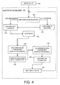
- FIG. 4 is a general block diagram illustrating components of the adaptive RLGR encoder 200 shown in FIG. 2.
- the adaptive RLGR encoder receives as input an input value (or string of values) 400.
- An encoder mode selector 405 then is used to select and switch between one of the two modes of the adaptive RLGR encoder 200.
- the encoder mode selector 405 can select either a Golomb/Rice only mode or a Run-Length and Golomb/Rice encoder mode.
- the Golomb/Rice only mode uses only a Golomb/Rice encoder 410 having adaptive parameters.
- the Run-Length and Golomb/Rice encoder mode uses both a Run-Length encoder 415 having adaptive parameters and the adaptive Golomb/Rice encoder 410.
- the adaptive RLGR encoder 200 uses at least two types of parameters. First, an encoding mode parameter is used to control whether the encoding mode uses the Run-Length encoder and, if so, how the Run-Length encoder is used. Second, a Golomb/Rice (G/R) parameter is used in both modes to: (a) encode every input value (if the encoder is in the G/R only mode; and (b) encode the number following an incomplete run of 0's (if the encoder is in the RLGR mode). These parameters and the adaptation of these parameters will be discussed in detail below.
- G/R Golomb/Rice
- An encoding mode parameter adaptation module 430 is used to update the encoding mode parameter using a backward-adaptive technique.
- the module 430 yields an update encoding mode parameter 435.
- a Golomb/Rice parameter adaptation module 440 is used to update the original G/R parameter using a backward-adaptive technique. This yields an updated G/R parameter 445.
- the adaptation of both the encoding mode parameter and the G/R parameter will be discussed in detail below.
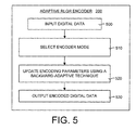
- FIG. 5 is a general flow diagram illustrating the general operation of the adaptive RLGR encoder 200 and method.
- the method begins by inputting digital data to be encoded (box 500).
- the input digital data is integer data in the form of a vector having elements that are integer values.
- the each input digital data value can be any integer value, not restricted to a particular range (e.g. binary or binary-plus-sign, as it is common in other entropy coders).
- the encoder mode of the adaptive RLGR encoder is selected (box 510). The mode can either be the G/R only mode or the RL+G/R mode, depending on the value of the encoding mode parameter.
- the selected encoder then encodes the input digital data.
- the digital data is encoded in the selected mode using encoding parameters that are initialized to certain values.
- the RLGR encoder 200 is adaptive. This adaptation allows the RLGR encoder 200 to track the statistics of the input digital data and adapt to those statistics quickly, to provide greater encoding efficiency.
- the RLGR encoder 200 and method update the encoding parameters using a backward-adaptive technique (box 520). This updating of the encoding parameters occurs after each value or string of values of the input digital data is encoded. Moreover, the backward-adaptive technique includes novel adaptation rules, which are discussed in detail below.
- the encoded digital data then is output (box 530). Next, the next value or string of the input digital data is processed using the method just described. The updated values of the encoding parameters are used in the encoding the next input value or string. This process is repeated until all the digital data has been encoded into an encoded bitstream.
- FIG. 6 is a flow diagram illustrating further details of the adaptive RLGR encoder and method shown in FIG. 5. Specifically, a value or string of the digital data is received as input (box 600). Next, an encoder mode is selected from one of the following modes: (a) a G/R only mode; and (b) a Run-Length and G/R mode (box 610). The input value or string then is encoded using the selected encoder mode (box 620).
- the encoding parameters are updated.
- This adaptation process begins by defining fractional adaptation parameters (box 630).
- the fractional adaptation parameters are used to slow down the adaptation of the encoding parameters such that the optimal parameter values can be more closely tracked.
- the fractional adaptation parameters are discussed in more detail below.
- the fractional adaptation version of the encoding mode parameter is updated using a backward-adaptive technique containing novel adaptation rules (box 640).
- the G/R parameter is updated using a backward-adaptive technique and novel adaptation rules (box 650).
- the encoded input value or string is appended to the encoded bitstream and the next value or string from the digital data to be encoded is input (box 660).
- the process begins again to encode the next value or string using the updated encoding mode parameter and G/R parameter.
- FIG. 7 is a detailed flow diagram of the operation of the encoder mode selector 405 of the adaptive RLGR encoder 200 and method shown in FIG. 4.
- the encoder mode selector 405 selects and switches between two encoder modes based on the value of an encoding mode parameter. The selection of an encoder mode occurs after a value or string of the digital data is encoded and the encoding parameters updated.
- the process begins by receiving as input an initial encoding mode parameter (box 705) and the input value (or string of zeros) to be encoded (box 710). A determination is made as to whether the value of the encoding mode parameter is equal to zero (box 715). If so, then the encoding mode is the G/R mode. Otherwise, the encoding mode is the RLGR mode.
- the input value is encoded using the adaptive G/R encoder (box 720).
- This is a G/R encoder that uses the backward-adaptive adaptation rules for the G/R parameter.
- the RLGR mode which means that the encoding mode parameter is greater than zero, it can be expected with a high probability that the input value contains a run of zeros.
- a determination is made as to whether the run of zeros is a complete or an incomplete run (box 725).
- a run is defined as a string of the same values adjacent each other.
- the input value string is encoded so as to tell the encoder that the run is incomplete, the number of zeros in the incomplete run, and the value immediately following the incomplete run.
- the length of the incomplete run is added to the encoded input value string (box 740).
- This encoded value represents the length of the incomplete run. For example, if the incomplete run is 4 zeros long, the value 4 (or "100" in binary notation) is added to the encoded bitstream to tell the decoder that the run length is equal to four.
- the only piece of information left to encode is that value immediately following the incomplete run.
- An adaptive G/R encoder is used to encode the value immediately following the incomplete run (box 745).
- the G/R parameter is used when using the adaptive G/R encoder.
- the encoded input value (if the encoding mode is the G/R mode) or the encoded input value string (if the encoding mode is the RLGR mode) is output (box 750).
- FIG. 8 is a detailed flow diagram of the operation of the encoding mode parameter adaptation module 430 of the adaptive RLGR encoder 200 and method shown in FIG. 4.
- the encoding mode parameter adaptation module 430 updates an initial encoding mode parameter using a backward-adaptive technique. The update is performed after each value or string of the digital data is encoded.
- the backward-adaptive technique uses novel adaptation rules to update the encoding mode parameter.
- the process begins by receiving as input the initial encoding mode parameter (box 805) and the input value to be encoded (box 810). A determination then is made as to whether the encoding mode parameter is equal to zero (box 815). If so, then the encoding mode is the G/R only mode, and otherwise the encoding mode is the RLGR mode.
- the current encoding mode parameter is replaced with the updated encoding mode parameter (box 850). This is obtained by dividing the scaled encoding mode parameter by a fixed scaling factor and keeping the integer part of the result. Since the adaptation adjusts the scaled encoding mode parameter by integer steps, the actual encoding parameter behaves as if it were adapted by fractional steps. This is called “fractional adaptation", which permits finer control of the speed of adaptation.
- the final updated encoding mode parameter then is output (box 855).
- the current scaled encoding mode parameter is updated after every input value or string is encoded. The updated encoding mode parameter then is used in the encoding of the next input value or string.
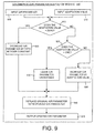
- FIG. 9 is a detailed flow diagram of the operation of the Golomb/Rice (G/R) parameter adaptation module 440 of the adaptive RLGR encoder 200 and method shown in FIG. 4.
- the G/R parameter adaptation module 440 updates an initial G/R parameter using a backward-adaptive technique having novel adaptation rules. The update is performed after each value or string of the digital data is encoded.
- the operation begins by receiving as input the initial G/R parameter (box 905) and an adaptation value (box 910), whose computation will be described later. A determination then is made as to whether the adaptation value equals zero (box 915). If so, then the adaptation rules are to decrease the scaled G/R parameter by a fifth integer constant (box 920).
- the current G/R parameter is replaced with the updated G/R parameter (box 940). This is obtained by dividing the scaled G/R mode parameter by a fixed scaling factor and keeping the integer part of the result. Since the adaptation adjusts the scaled G/R mode parameter by integer steps, the actual G/R parameter behaves as if it were adapted by fractional steps. Again, this is an example of "fractional adaptation", which permits finer control of the speed of adaptation. Of course, if the G/R parameter is left unchanged (box 930) then there is no updating to perform, and the current G/R parameter is the same. Finally, the updated G/R parameter is output (box 945).
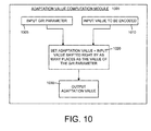
- FIG. 10 is a detailed flow diagram of the operation of an adaptation value computation module 1000.
- the adaptation value computation module 1000 produces the adaptation value (box 910) that is an input to the flow diagram in FIG. 9.
- the operation begins by receiving two inputs, the current G/R parameter value (box 1005) and the input value (box 1010) to the Golomb/Rice encoders (boxes 720 and 745) of FIG. 7. Next, the input value is shifted to the right by as many places as the value of the G/R parameter (box 1020). The resulting value is the adaptation value, which then is output (box 1030).
- the Run-Length Golomb/Rice (RLGR) encoder and method is an extension of the PTC entropy encoder disclosed in U.S. Patent No. 6,477,280 cited above.
- the PTC entropy encoder of U.S. Patent No. 6,477,280 is used for encoding binary data (typically bit-planes of integer data).
- the RLGR encoder and method disclosed herein can encode integer data having any input value.
- the adaptive RLGR encoder and method disclosed herein can encode data of any alphabet.
- the RLGR encoder and method disclosed herein can handle any size input value, no matter how large. This means that the RLGR encoder assumes that the input data has a Laplacian distribution as shown in FIG. 1, and suddenly a large number appears in the input data, the RLGR encoder and method is able to encode that large number. While more bits will be used to encode that large number than a smaller number, the large number will be encoded. However, the penalty using more bits will only be paid for that large number when it occurs, and not for every other value. This is due to the new mode selection and adaptation rules set forth below.
- the input data is received, broken into bit planes, and then each bit plane is encoded with a G/R encoder.
- the G/R encoder is extended to the handle Laplacian data directly. This has the advantage that the adaptive RLGR encoder and method uses single-pass encoding, which makes is significantly faster than the PTC entropy encoder.
- the input data of the PTC entropy encoder had a Laplacian distribution, where small numbers are more likely. Sometimes small numbers are so much more likely that encoding runs of zeros is more efficient for a particular part of the bitstream.
- the PTC entropy encoder would pick up the data, do one pass on the most significant bit plane, and go back and do one pass in the next bit plane. For example, if the data was 16 bits, a pass was first done on bit #16 and encoded. Of course, most of the data will be zero, because that bit only gets split for very large numbers, then keeps going down. As bits #5, 4, 3, 2, and 1 are reached these bits have lots of zeros and ones, which means that it gets to a point that encoding them does not help at all.
- the least significant bit is so random that a bit has to be used to encode the bit, that is, each input bit is directly copied to the output.
- the problem with the PTC entropy encoder is that encoding in bit planes requires several passes at the data. In particular, the PTC entropy encoder has to encode the most significant bit, the next bit, then the next bit, and so on. Clearly, this will take significantly more time, and in some cases the PTC entropy encoder is 1.5 to 3 times slower than the adaptive RLGR encoder and method disclosed herein.
- FIG. 11 is a working example illustrating the details of selecting an encoder mode for the adaptive RLGR encoder and method.
- the input vector has a probability distribution similar to the Laplacian distribution shown in FIG. 1.
- the probability distribution is represented by a single parameter, which is the rate of decay of the exponential.
- the Laplacian decay in shown in FIG. 1 goes down reasonably fast. In practice the decay typically can be either faster or slower. The faster the rate of decay, then the more likely are values equal to zero.
- the adaptive RLGR encoder and method is useful for the efficient encoding of integers. Specifically, this occurs when there is a vector (or buffer) full of integer numbers that need to be encoded efficiently. Typically, the integer data will be such that small numbers are much more likely than large numbers. And if the rate of decay of the probability distribution of the data is high enough (meaning the exponential decays fast), this means that zero becomes even more likely. In this case encoding runs of zeros is a good idea.
- the input data has a probability distribution similar to the ideal shown in FIG. 1 because the data being encoded (or the input data) is not the original multimedia data.
- the adaptive RLGR encoder and method is not applied directly to every audio sample.
- the adaptive RLGR encoder and method is not applied to every pixel value.
- prediction error can be the input data, and it is the prediction error that is encoded. Prediction error is the difference between the actual value and the predicted value.
- prediction errors are much more likely to be zero if the model for the data is reasonable. It is possible, however, even with a good model, to every once in a while have a large value. This can occur when a boundary is reached, such as when a pixel value goes from a background value to a foreground value. In other words, even with a probability distribution like that shown in FIG. 1, every now and then big numbers can appear.
- the original data values e.g. audio samples or pixels
- a transform operator whose goal is to concentrate the information in a small number of large-valued transform coefficients, and a large number of small-valued transform coefficients. These coefficients are then quantized (rounded to nearest integers).
- the elements of that vector are more likely to contain small values, and thus are quite amenable to compression via the adaptive RLGR encoder and method disclosed herein.
- the adaptive RLGR encoder and method is lossless.
- Lossless compression means that the input data is compressed in to a smaller size and then decoded to recover exactly the same values of the input data as the original. In contrast, lossy compression does not recover exactly the same value of original input data.
- Audio and video compression can use lossy compression.
- transforms or predictors are generated for the data. The transform or predictors then are quantized, meaning that they are rounded to the nearest integer. Once these integers are obtained, lossless compression frequently is used. This means that most lossy codecs for multimedia usually have a lossless encoder portion to encode the integer values of the quantized prediction or transform operators.
- the adaptive RLGR encoder and method can be used to encode these integer values. Usually, each of these integer values has an associated probability distribution function (PDF). These PDFs are similar to the probability distribution of FIG. 1, in the sense that if the model is good then the prediction error should be close to zero most of the time.
- PDF probability distribution function
- the encoding parameters ⁇ s, S ⁇ and ⁇ k, K ⁇ are initialized (box 1115).
- the counter n and run then are set to zero (box 1120).
- the s is the encoding mode parameter
- S is the scaled encoding mode parameter
- k is the G/R parameter
- K is the scaled G/R parameter.
- s controls the encoding mode and how the Run-Length encoder is used, and k controls the G/R encoder.
- the parameter s S/L, where L is a scaling parameter.
- L is equal to 16, which is a power of 2. This allows division to be performed by merely doing a shift.
- the adaptive RLGR encoder and method has two distinct encoding modes.
- a first encoding mode performs Golomb/Rice (G/R) encoding only, without any Run-Length encoding. This G/R only mode is applied when zero is not that much more likely in the data, such that there will not be runs of zeros that frequently.
- the second encoding mode performs Run-Length plus G/R encoding. This RLGR encoding mode is used when runs of zeros are so much more likely in the input data such that encoding the runs of zeros saves bits.
- G/R Golomb/Rice
- the adaptive RLGR encoder and method uses novel encoding rules that are based on the encoding mode parameter, s , and the G/R parameter, k .
- Table 2 sets forth the coding rules for the adaptive RLGR encoder and method for mapping integer values x to a binary bitstream.
- code is controlled by parameters ⁇ s, k ⁇ .
- Parameter s controls the main mode of operation (G/R only or Run-Length + GR), and parameter k controls the G/R coder.
- a mapping value, u is defined.
- the input values, x, of the adaptive RLGR encoder and method can be positive or negative.
- the input value x is mapped to a u value, where u is only positive.
- the signed input value, x is converted into an unsigned equivalent representation, u .
- Equation 4 sets forth the mapping from x to u .
- the mapping says that 0 maps to 0, 1 maps to 1, -1 maps to 2, 2 maps to 3, -2 maps to 4, and so forth, such that the u value is always positive. This is done so the G/R table (Table 1) can be used, because the G/R table is only for nonnegative values.
- This mapping allows the adaptive RLGR encoder and method to handle any input alphabet.
- the G/R table is used (which can handle any input number), the input alphabet can be infinite and the adaptive RLGR encoder and method can handle any size number input.
- the adaptive RLGR encoder and method is only limited by the size of the numbers that the operating system can handle. It should be noted that in practice the G/R encoding Table 1 does not need to be stored in memory. It is easy to see that the table entries have enough structure that the codewords can be easily computed for any value of u and the encoding parameter k.
- Table 2 states the code that goes in the channel as long as the parameters s and k are known.
- the rules in Table 2 precisely define how the encoder encodes, which means that the decoder can use the same rules in Table 2 to recover (or decode) the encoded data.
- Table 2 states that the mapping value u of the input value x is encoded using an adaptive G/R encoder and the G/R encoding rule exemplified by Table 1.
- the codeword used to encode x is based on the values of u and k .
- the G/R parameter k is updated using a backward-adaptive technique, as discussed in detail below.
- s 3.
- the entire run of 8 zeros is mapped to a single bit whose value is 0.
- the decoder knows that if it reads a 0 it has to decode that into a string of 2 s zeros. In this situation, maximum compression is achieved.
- the overall compression achieved by the invention is an average of this RLGR mode and the G/R mode.
- the codeword contains a binary representation of the length of the incomplete run. This binary representation uses s bits to specify the length of the incomplete run, r .
- the codeword next is appended to state what value comes immediately after the incomplete run.
- This value that comes after the incomplete run is represented by a codeword from the adaptive G/R encoder.
- Table 2 first the value after the incomplete run is mapped by using Equation 4. Then, the adaptive G/R encoder is used to obtain a G/R code that is a function of ⁇ u , k ⁇ .
- Fractional adaptation uses S and K instead of s and k . Fractional adaptation is a way to slow down adaptation. It is possible to use the adaptive RLGR encoder and method without fractional adaptation. However, without fractional adaptation the adaptation usually changes too quickly and typically fails to track the optimal parameters for the input data correctly.
- the adaptation of the s and k parameters is performed using the scaled S and K parameters.
- S and K are updated instead of s and k.
- L is a scaling parameter as explained above.
- the value of S is adapted and S is divided by L to obtain the value of s.
- Fractional adaptation is preferred because the adaptive RLGR encoder and method makes an adjustment of the parameters (s and k) for every code that is generated.
- the adaptation rules are run. If s and k are adapted directly via integer-valued changes, then because they are integer numbers, all that can be done is stay the same or increase or decrease by at least 1.
- the next string it would find s to be too big, and decrease s to 3. However, this may be too small, and s would be oscillating.
- fractional adaptation it is possible to define a flag such that if there is a decrease or increase in the data then a certain number of encoding cycles passes before increasing or decreasing the parameters.
- a new parameter could be defined that keeps track of the number of encoding cycles. In other words, the parameter would keep track of how many times that the condition (input data increasing or decreasing) should happen before the parameters are changed. It should be noted, however, that this technique was tried, and the fractional adaptation provided superior results.
- the encoding mode parameter s is adapted after each input value or string is encoded.
- the fractional encoding mode parameter S is actually adapted, instead of s directly.
- Table 3 s 0
- 0 : S ⁇ S + A1 "Golomb/Rice only" mode
- FIG. 12 is a working example illustrating the encoding details of the G/R only mode and the accompanying encoding mode parameter s adaptation.
- the process begins (box 1205) by reading the input vector x (n) (box 1210).
- the two main processes of the G/R only mode are Symbol Encoding (box 1215) and Encoding Mode Parameter Adaptation (box 1220).
- the Symbol Encoding process begins by defining the mapping value u (box 1225), as shown in Table 2 for the G/R only mode.
- the input value is encoded using the adaptive G/R encoder (box 1230).
- the adaptive G/R encoder uses G/R parameter k adaptation, as shown in FIG. 14.
- the Symbol Encoding process ends by appending the G/R code to the output encoding bitstream (box 1235).
- the Encoding Mode Parameter Adaptation process begins by determining whether the value of u equals zero (box 1240). If not, then S is updated and replaced by S increased by the first integer constant, A1 (box 1245). If u is not equal to zero, then S is updated and replaced by S decreased by the second integer constant, B1 (box 1250). Finally, s is set equal to S divided by L (box 1255), and the process is finished (box 1260).
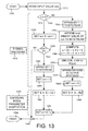
- FIG. 13 is a working example illustrating the encoding details of the RLGR mode and the accompanying encoding mode parameter s adaptation.
- the process begins (box 1305) by reading the input vector x(n) (box 1310).
- the two main processes of the RLGR mode are Symbol Encoding (box 1315) and Encoding Mode Parameter Adaptation (box 1320). This time, however, the Symbol Encoding process uses an adaptive Run-Length encoder and an adaptive G/R encoder to encode the input value x(n).
- the bit 1 is appended to the bitstream (box 1355).
- an s-bit binary value of run (or the length of the incomplete run represented by s bits) is appended to the bitstream (box 1360).
- the value after the incomplete run then is encoded using the adaptive G/R encoder.
- the mapping value u is defined (box 1365), the value is encoded using the adaptive G/R encoder, and the G/R is appended to the bitstream (box 1370).
- the adaptive G/R encoder uses G/R parameter k adaptation, as shown in FIG. 14.
- the Symbol Encoding process ends by setting run equal to zero (box 1380).
- the Encoding Mode Parameter Adaptation process updates and replaces S with S increased by the third integer constant, A2 (box 1385), if the value of x is equal zero (box 1325). If the value of x is not equal to zero (box 1325), then S is updated and replaced with S decreased by the fourth integer constant, B2 (box 1390). Finally, the process sets s equal to S divided by L (box 1395) and the process finishes (box 1398). As mentioned before, division by L can be implemented via a shift operation, if the value of L is chosen as a power of two.
- the G/R parameter k is adapted after each input value or string is encoded.
- the scaled G/R parameter K is actually adapted, instead of k directly.
- the G/R code from Table 1 depends on the parameter k .
- the parameter k must be known. This means that the adaptive RLGR encoder and method can do a good job if it chooses a good value for s and for k .
- it is not always advantageous to use large values of k because it will produce longer strings for smaller values of the input data, as shown in Table 1.
- a good choice for the value of k depends on the input data. If the value is 13, then using a large value of k is a good idea. However, suppose that the value after the incomplete run is "1". Then, a smaller value of k is desirable. Thus, for small values after the incomplete run, it is better to use a small k, and for large values it is better to use a large k. Thus, the choice of k is related to the probability of the values.
- the probability for the input data is known (for example, if the input data is Laplacian where there is a single parameter than controls the decay), there are well-known formulas that from that decay parameter the parameter k to be used can be computed. This gives on average the mapping to use as few bits as possible.
- the k parameter it is important for the k parameter to be adaptive. That way, if on the input data there are big values coming up, k should be increased, because for big values larger k is better. On the other hand, if there are smaller values coming up, k should be decreased. Instinctively, it can be seen that for big numbers k should be increased and for small numbers k should be decreased. Then as long as k is changed at a small enough pace (such as when using fractional adaptation), the optimal parameters for the input data will always be tracked correctly.
- the adaptation rules for k shown in Table 4 are significantly new. In the adaptive RLGR encoder and method, any value can come after the incomplete runs of zeros, so this value must be encoded.
- the encoding is done using the adaptive G/R encoder and the G/R parameter k. Referring to Table 4, the input data is x.
- the input data x can be any integer number, small x's are more likely (can be positive or can be negative). However, G/R encoding is only for positive numbers.
- a straightforward mapping of x is used (see equation 4) to map x into u .
- the adaptation of k is controlled by the adaptation value p , which is defined as u shifted to the right k places. Thus, the adaptation value p is a scaled down version of u.
- the p parameter is an integer approximation to u / 2 k . Shifting k places to the right is equivalent to dividing the number by 2 k . For example, if a number is shifted 5 bits to the right this is the same as dividing the number by 32 (or 2 5 ). The remainder is thrown away, and just the quotient is used.
- the adaptation value of p is equal to one, it means that the value of u was close to 2 k , and those are the kinds of values for which the parameter k is correct. Thus, as shown in Table 4, there is no change. If the value of the adaptation value p is 0, which means that the input value was smaller than 2 k . This means it is time to start decreasing k (because the input values are smaller than 2 k ). The case where the adaptation value p is greater than 1 is much less likely because the input values are not likely to be very big. But if the numbers are big and p > 1, then it is time to start increasing the k parameter.
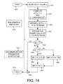
- FIG. 14 is a working example illustrating the encoding details of the adaptive G/R encoding module, including the G/R parameter k adaptation rules. It should be noted that the k adaptation is used in both the G/R only mode and the RLGR mode but is not shown in FIGS. 12 and 13 to avoid cluttering the drawings.
- the process begins (box 1405) by reading the input value u (box 1410).
- the two main processes of the adaptive G/R mode are G/R Encoding (box 1415) and G/R Parameter Adaptation (box 1420).
- the G/R Encoding process begins by computing an adaptation value p and v (box 1425).
- the bitstream is appended with p bits equal to one (box 1430).
- the k -bit binary value of v then is appended to the bitstream (box 1435).
- These operations comprise the Golomb/Rice encoder as defined in Table 1.
- the G/R Parameter Adaptation process includes determining whether the adaptation value p is equal to one (box 1440). If so, then the adaptation value p is left unchanged (point 1445). Otherwise, another determination is made whether the adaptation value p equals zero (box 1450). If not, then K is updated and replaced by K decreased by the fifth integer constant, B3 (box 1455). Otherwise, K is updated and replaced by K increased by the adaptation value p (box 1460). Finally, the process sets k equal to K divided by L (box 1465) and the process finishes (box 1470).
- the RLGR encoder and method of this working example has been implemented in applications for image, audio, and map data compression.
- the results of using the RLGR encoder and method in these applications have been compression ratios that are comparable to the most sophisticated entropy coders, but in a simpler implementation.
- the RLGR encoder and method achieves compression rates near the theoretical maximum (dictated by the source entropy) for a large class of source symbol probability distributions, like the one in FIG. 1.
- well-known Golomb-Rice and Huffman encoders are efficient only for source entropies of 1 bit per symbol or higher.
- the adaptive RLGR codec and method also includes a decoder that can be precisely implemented based on the encoder description above.
- a computing device can implement just an RLGR decoder 240.
- An adaptive RLGR decoder 240 and method receives codewords from an encoded bitstream (box 230).
- the adaptive RLGR decoder 240 decodes the codewords by applying the reverse rules corresponding to those in the G/R-only mode or the RLGR mode.
- the encoding mode and G/R parameters are adapted using exactly the same rules as those for the encoder (described above).
- the decoded (reconstructed) integer data is output (box 260).
Applications Claiming Priority (2)
| Application Number | Priority Date | Filing Date | Title |
|---|---|---|---|
| US10/976,623 US7015837B1 (en) | 2004-10-29 | 2004-10-29 | Lossless adaptive encoding and decoding of integer data |
| US10/978,157 US6987468B1 (en) | 2004-10-29 | 2004-10-29 | Lossless adaptive encoding and decoding of integer data |
Publications (2)
| Publication Number | Publication Date |
|---|---|
| EP1653746A2 true EP1653746A2 (fr) | 2006-05-03 |
| EP1653746A3 EP1653746A3 (fr) | 2006-05-10 |
Family
ID=35929810
Family Applications (1)
| Application Number | Title | Priority Date | Filing Date |
|---|---|---|---|
| EP05109484A Withdrawn EP1653746A3 (fr) | 2004-10-29 | 2005-10-12 | Codage et décodage sans pertes de données entières |
Country Status (3)
| Country | Link |
|---|---|
| EP (1) | EP1653746A3 (fr) |
| JP (1) | JP2006129467A (fr) |
| KR (1) | KR20060051157A (fr) |
Cited By (6)
| Publication number | Priority date | Publication date | Assignee | Title |
|---|---|---|---|---|
| EP2448124A1 (fr) * | 2009-06-22 | 2012-05-02 | Universidad de Barcelona | Procédé pour l'étalonnage entièrement adaptatif d'un codeur d'erreurs de prédiction |
| WO2014169199A3 (fr) * | 2013-04-12 | 2014-12-18 | Qualcomm Incorporated | Mise à jour de paramètre de rice pour codage de niveau de coefficient dans un processus de codage vidéo |
| US10021419B2 (en) | 2013-07-12 | 2018-07-10 | Qualcomm Incorported | Rice parameter initialization for coefficient level coding in video coding process |
| CN111885385A (zh) * | 2019-05-02 | 2020-11-03 | 西克Ivp股份公司 | 关于实现数字图像的无损压缩的像素值编码方法及编码器 |
| EP3661062A4 (fr) * | 2017-07-25 | 2021-04-28 | Nippon Telegraph And Telephone Corporation | Dispositif de codage, dispositif de décodage, structure de données de chaîne de code, procédé de codage, procédé de décodage, programme de codage et programme de décodage |
| CN116505952A (zh) * | 2023-06-27 | 2023-07-28 | 厦门立林科技有限公司 | 红外码压缩方法、装置、智能设备及存储介质 |
Families Citing this family (3)
| Publication number | Priority date | Publication date | Assignee | Title |
|---|---|---|---|---|
| JP4655013B2 (ja) * | 2006-09-15 | 2011-03-23 | 日本電気株式会社 | 符号化装置とその方法、復号装置とその方法、および符号化ならびに復号プログラム |
| KR100903109B1 (ko) * | 2006-12-13 | 2009-06-16 | 한국전자통신연구원 | 오디오 신호의 무손실 부호화/복호화 장치 및 그 방법 |
| JP6512927B2 (ja) * | 2015-04-28 | 2019-05-15 | キヤノン株式会社 | 画像符号化装置及びその制御方法 |
Family Cites Families (5)
| Publication number | Priority date | Publication date | Assignee | Title |
|---|---|---|---|---|
| JP3847891B2 (ja) * | 1997-04-10 | 2006-11-22 | キヤノン株式会社 | 符号化装置及び方法及び方法を記憶した記憶媒体 |
| JP3839974B2 (ja) * | 1998-10-06 | 2006-11-01 | キヤノン株式会社 | 符号化装置 |
| JP2000115782A (ja) * | 1998-10-06 | 2000-04-21 | Canon Inc | 符号化装置及び方法及び記憶媒体 |
| KR100304798B1 (ko) * | 1999-08-11 | 2001-11-01 | 정병철 | 애니메이션 동영상 부호화 방법 |
| US6735254B2 (en) * | 2001-06-29 | 2004-05-11 | Qualcomm, Inc. | DCT compression using Golomb-Rice coding |
-
2005
- 2005-09-09 KR KR1020050084137A patent/KR20060051157A/ko not_active Application Discontinuation
- 2005-09-29 JP JP2005284786A patent/JP2006129467A/ja active Pending
- 2005-10-12 EP EP05109484A patent/EP1653746A3/fr not_active Withdrawn
Non-Patent Citations (1)
| Title |
|---|
| None * |
Cited By (10)
| Publication number | Priority date | Publication date | Assignee | Title |
|---|---|---|---|---|
| EP2448124A1 (fr) * | 2009-06-22 | 2012-05-02 | Universidad de Barcelona | Procédé pour l'étalonnage entièrement adaptatif d'un codeur d'erreurs de prédiction |
| EP2448124A4 (fr) * | 2009-06-22 | 2012-08-29 | Univ Barcelona | Procédé pour l'étalonnage entièrement adaptatif d'un codeur d'erreurs de prédiction |
| WO2014169199A3 (fr) * | 2013-04-12 | 2014-12-18 | Qualcomm Incorporated | Mise à jour de paramètre de rice pour codage de niveau de coefficient dans un processus de codage vidéo |
| US9936200B2 (en) | 2013-04-12 | 2018-04-03 | Qualcomm Incorporated | Rice parameter update for coefficient level coding in video coding process |
| US10021419B2 (en) | 2013-07-12 | 2018-07-10 | Qualcomm Incorported | Rice parameter initialization for coefficient level coding in video coding process |
| EP3661062A4 (fr) * | 2017-07-25 | 2021-04-28 | Nippon Telegraph And Telephone Corporation | Dispositif de codage, dispositif de décodage, structure de données de chaîne de code, procédé de codage, procédé de décodage, programme de codage et programme de décodage |
| CN111885385A (zh) * | 2019-05-02 | 2020-11-03 | 西克Ivp股份公司 | 关于实现数字图像的无损压缩的像素值编码方法及编码器 |
| CN111885385B (zh) * | 2019-05-02 | 2023-11-28 | 西克Ivp股份公司 | 关于实现数字图像的无损压缩的像素值编码方法及编码器 |
| CN116505952A (zh) * | 2023-06-27 | 2023-07-28 | 厦门立林科技有限公司 | 红外码压缩方法、装置、智能设备及存储介质 |
| CN116505952B (zh) * | 2023-06-27 | 2023-09-08 | 厦门立林科技有限公司 | 红外码压缩方法、装置、智能设备及存储介质 |
Also Published As
| Publication number | Publication date |
|---|---|
| KR20060051157A (ko) | 2006-05-19 |
| JP2006129467A (ja) | 2006-05-18 |
| EP1653746A3 (fr) | 2006-05-10 |
Similar Documents
| Publication | Publication Date | Title |
|---|---|---|
| US7126506B2 (en) | Lossless adaptive encoding and decoding of integer data | |
| US7245235B2 (en) | Lossless adaptive encoding and decoding of integer data | |
| EP1653628B1 (fr) | Codage de Golomb/Rice adaptatif sans perte et décodage de nombres entiers utilisant des règles d'adaptation arrière | |
| US10045034B2 (en) | System and method for using pattern vectors for video and image coding and decoding | |
| EP1653746A2 (fr) | Codage et décodage sans pertes de données entières | |
| Malvar | Adaptive run-length/Golomb-Rice encoding of quantized generalized Gaussian sources with unknown statistics | |
| RU2417518C2 (ru) | Эффективное кодирование и декодирование блоков преобразования | |
| US20060171533A1 (en) | Method and apparatus for encoding and decoding key data | |
| US20040059770A1 (en) | Method and apparatus for arithmetic coding, including probability estimation state table creation | |
| RU2426227C2 (ru) | Кодирование кодов переменной длины с эффективным использованием памяти | |
| WO1996015620A1 (fr) | Codeur/decodeur d'image sans perte, adaptatif et dependant du contexte | |
| US8199820B2 (en) | Intermediate compression of reference frames for transcoding | |
| KR20070046852A (ko) | 혼합된 그래픽 및 비디오 소스의 압축을 위한 시스템 및방법 | |
| WO2016025282A1 (fr) | Procédé pour coder des vecteurs d'impulsion en utilisant des propriétés statistiques | |
| Belyaev et al. | An efficient adaptive binary arithmetic coder with low memory requirement | |
| US7728739B2 (en) | Entropy codec with variable divisor | |
| US9990931B2 (en) | Method for coding pulse vectors using statistical properties | |
| US20100002946A1 (en) | Method and apparatus for compressing for data relating to an image or video frame | |
| KR20040075944A (ko) | 디지털 정보신호의 데이터 압축 및 압축해제 | |
| EP3180863B1 (fr) | Procédé pour coder des vecteurs d'impulsion en utilisant des propriétés statistiques | |
| CN106664099B (zh) | 使用统计特性编码脉冲矢量的方法 | |
| EP1841237B1 (fr) | Procédé et appareil pour le codage vidéo | |
| Wu et al. | Enhanced video compression with standardized bit stream syntax | |
| EP3991303A1 (fr) | Caractéristiques de codage et de décodage de système de nombres asymétrique de portée | |
| US20160323603A1 (en) | Method and apparatus for performing an arithmetic coding for data symbols |
Legal Events
| Date | Code | Title | Description |
|---|---|---|---|
| PUAI | Public reference made under article 153(3) epc to a published international application that has entered the european phase |
Free format text: ORIGINAL CODE: 0009012 |
|
| PUAL | Search report despatched |
Free format text: ORIGINAL CODE: 0009013 |
|
| AK | Designated contracting states |
Kind code of ref document: A2 Designated state(s): AT BE BG CH CY CZ DE DK EE ES FI FR GB GR HU IE IS IT LI LT LU LV MC NL PL PT RO SE SI SK TR |
|
| AX | Request for extension of the european patent |
Extension state: AL BA HR MK YU |
|
| AK | Designated contracting states |
Kind code of ref document: A3 Designated state(s): AT BE BG CH CY CZ DE DK EE ES FI FR GB GR HU IE IS IT LI LT LU LV MC NL PL PT RO SE SI SK TR |
|
| AX | Request for extension of the european patent |
Extension state: AL BA HR MK YU |
|
| 17P | Request for examination filed |
Effective date: 20061030 |
|
| 17Q | First examination report despatched |
Effective date: 20061214 |
|
| AKX | Designation fees paid |
Designated state(s): AT BE BG CH CY CZ DE DK EE ES FI FR GB GR HU IE IS IT LI LT LU LV MC NL PL PT RO SE SI SK TR |
|
| RAP1 | Party data changed (applicant data changed or rights of an application transferred) |
Owner name: MICROSOFT TECHNOLOGY LICENSING, LLC |
|
| STAA | Information on the status of an ep patent application or granted ep patent |
Free format text: STATUS: THE APPLICATION IS DEEMED TO BE WITHDRAWN |
|
| 18D | Application deemed to be withdrawn |
Effective date: 20190924 |