EP1653632B1 - Verfahren zum Betrieb eines Nahfeld-Kommunikationssystems - Google Patents
Verfahren zum Betrieb eines Nahfeld-Kommunikationssystems Download PDFInfo
- Publication number
- EP1653632B1 EP1653632B1 EP04025775.0A EP04025775A EP1653632B1 EP 1653632 B1 EP1653632 B1 EP 1653632B1 EP 04025775 A EP04025775 A EP 04025775A EP 1653632 B1 EP1653632 B1 EP 1653632B1
- Authority
- EP
- European Patent Office
- Prior art keywords
- near field
- field communication
- communication device
- initiator
- participating near
- Prior art date
- Legal status (The legal status is an assumption and is not a legal conclusion. Google has not performed a legal analysis and makes no representation as to the accuracy of the status listed.)
- Expired - Fee Related
Links
- 230000006854 communication Effects 0.000 title claims description 169
- 238000004891 communication Methods 0.000 title claims description 163
- 238000000034 method Methods 0.000 title claims description 62
- 239000003999 initiator Substances 0.000 claims description 64
- 230000008569 process Effects 0.000 claims description 24
- 238000004590 computer program Methods 0.000 claims description 5
- 230000003993 interaction Effects 0.000 description 6
- 238000010586 diagram Methods 0.000 description 2
- 238000005516 engineering process Methods 0.000 description 2
- 230000005855 radiation Effects 0.000 description 2
- LZDYZEGISBDSDP-UHFFFAOYSA-N 2-(1-ethylaziridin-1-ium-1-yl)ethanol Chemical compound OCC[N+]1(CC)CC1 LZDYZEGISBDSDP-UHFFFAOYSA-N 0.000 description 1
- 230000009471 action Effects 0.000 description 1
- 230000005540 biological transmission Effects 0.000 description 1
- 238000004364 calculation method Methods 0.000 description 1
- 230000001419 dependent effect Effects 0.000 description 1
- 230000002452 interceptive effect Effects 0.000 description 1
- 230000007246 mechanism Effects 0.000 description 1
- 230000008685 targeting Effects 0.000 description 1
Images


Classifications
-
- G—PHYSICS
- G06—COMPUTING; CALCULATING OR COUNTING
- G06K—GRAPHICAL DATA READING; PRESENTATION OF DATA; RECORD CARRIERS; HANDLING RECORD CARRIERS
- G06K7/00—Methods or arrangements for sensing record carriers, e.g. for reading patterns
- G06K7/0008—General problems related to the reading of electronic memory record carriers, independent of its reading method, e.g. power transfer
-
- G—PHYSICS
- G06—COMPUTING; CALCULATING OR COUNTING
- G06K—GRAPHICAL DATA READING; PRESENTATION OF DATA; RECORD CARRIERS; HANDLING RECORD CARRIERS
- G06K7/00—Methods or arrangements for sensing record carriers, e.g. for reading patterns
- G06K7/10—Methods or arrangements for sensing record carriers, e.g. for reading patterns by electromagnetic radiation, e.g. optical sensing; by corpuscular radiation
- G06K7/10009—Methods or arrangements for sensing record carriers, e.g. for reading patterns by electromagnetic radiation, e.g. optical sensing; by corpuscular radiation sensing by radiation using wavelengths larger than 0.1 mm, e.g. radio-waves or microwaves
- G06K7/10019—Methods or arrangements for sensing record carriers, e.g. for reading patterns by electromagnetic radiation, e.g. optical sensing; by corpuscular radiation sensing by radiation using wavelengths larger than 0.1 mm, e.g. radio-waves or microwaves resolving collision on the communication channels between simultaneously or concurrently interrogated record carriers.
- G06K7/10029—Methods or arrangements for sensing record carriers, e.g. for reading patterns by electromagnetic radiation, e.g. optical sensing; by corpuscular radiation sensing by radiation using wavelengths larger than 0.1 mm, e.g. radio-waves or microwaves resolving collision on the communication channels between simultaneously or concurrently interrogated record carriers. the collision being resolved in the time domain, e.g. using binary tree search or RFID responses allocated to a random time slot
-
- G—PHYSICS
- G06—COMPUTING; CALCULATING OR COUNTING
- G06K—GRAPHICAL DATA READING; PRESENTATION OF DATA; RECORD CARRIERS; HANDLING RECORD CARRIERS
- G06K7/00—Methods or arrangements for sensing record carriers, e.g. for reading patterns
- G06K7/10—Methods or arrangements for sensing record carriers, e.g. for reading patterns by electromagnetic radiation, e.g. optical sensing; by corpuscular radiation
- G06K7/10009—Methods or arrangements for sensing record carriers, e.g. for reading patterns by electromagnetic radiation, e.g. optical sensing; by corpuscular radiation sensing by radiation using wavelengths larger than 0.1 mm, e.g. radio-waves or microwaves
- G06K7/10237—Methods or arrangements for sensing record carriers, e.g. for reading patterns by electromagnetic radiation, e.g. optical sensing; by corpuscular radiation sensing by radiation using wavelengths larger than 0.1 mm, e.g. radio-waves or microwaves the reader and the record carrier being capable of selectively switching between reader and record carrier appearance, e.g. in near field communication [NFC] devices where the NFC device may function as an RFID reader or as an RFID tag
-
- H04B5/48—
-
- H—ELECTRICITY
- H04—ELECTRIC COMMUNICATION TECHNIQUE
- H04B—TRANSMISSION
- H04B7/00—Radio transmission systems, i.e. using radiation field
Definitions
- the present invention relates to a method for operating a near field communication system.
- the present invention in particular relates to a method to increase the probability of best fitting NFC device type selection during NFC initial start up phase in order to save power.
- Examples for near field communication systems or NFC systems are for instance based on the interaction between an intelligent device which in many cases is a so-called intelligent card reader, a card which is capable of carrying and transmitting information from a storage means to the intelligent device or card reader.
- the interaction between the card reader and the card is for example realized by radiation or radiation connection, for instance by using so-called contactless chip cards.
- An intelligent device is referred to be a device which has a certain degree of processing and/or calculation power in order to comply with higher services.
- a basic aspect of a near field communication is the usage of electromagnetic waves in radio frequency range and that the transmission of the information content is realized over a short distance only, for instance in the range of several centimetres only.
- This principle of short range information exchange by exchanging electromagnetic waves in the radio frequency range might be used in order to establish a communication between two intelligent devices for short range communication.
- no general concept is known how to establish the respective communication in an easy and reliable manner and further without the burden of user interaction. It is a particular problem that establishing a communication connection without user guidance might be difficult as participating near field communication devices are with reasonable probability in a same operational state, so that a communication can hardly be established.
- WO 2004/056005 A1 describes two near field communication devices each having a passive and an active mode for communicating
- a first near communication field device transmits data by modulating its own generated, electromagnetic waves while the second near communication field device load-modulates the electromagnetic waves generated by the first device for transmitting data.
- both near field communication devices transmit data by modulating their own generated electromagnetic waves.
- EP 0 600 695 A2 describes a near field coupled communication system having a plurality of base stations and portable stations for providing two-way communication services within a predetermined service area.
- US 3,968,435 describes a close range communication system allowing person to person communication over short distances without interfering with other communication systems.
- the object is achieved by a method for operating a near field communication system according to independent claim 1. Preferred embodiments of the inventive method for operating a near field communication system are within the scope of the dependent sub-claims.
- the object is further achieved by a system or apparatus according to independent claim 13, by a near field communication device according to independent claim 14, and by a computer program product according to independent claim 15.
- the inventive method for operating a near field communication system is e.g. adapted for a near field communication system of at least a first and a second participating near field communication device.
- an idle process is performed by repeatedly changing the respective participating near field communication devices operational state or mode between a target operational state or mode and an initiator operational state or mode until communication is established between said respective participating near field communication device and another participating near field communication device or until an interruption condition is fulfilled.
- a target operational state is an operational state of a participating near field communication device during an established communication process in which said participating near field communication device acts as a target or target device, i.e. it receives an RF signal from another participating near field communication device.
- a target operational mode is an operational mode of a participating near field communication device in which said participating near field communication device acts at least like a target or target device, i.e. it is at least listening and/or searching for an RF signal signal from another participating near field communication device, but without the necessity of an an established communication process.
- an initiator operational state is an operational state of a participating near field communication device during an established communication process in which said participating near field communication device acts as an initiator or initiator device, i.e. it sends out an RF signal to another connected participating near field communication device.
- a initiator operational mode is an operational mode of a participating near field communication device in which said participating near field communication device acts at least like an initiator or initiator device, i.e. it is at least sending out an initial RF polling signal, but without the necessity of the presence of or a connection to another participating near field communication device and therefore without the necessity of an an established communication process.
- said method may additionally or alternatively comprise an initialization section for each of said participating near field communication devices in order to try to establish and to setup a connection and a communication between a respective participating near field communication device and another one of said participating near field communication device wherein said idle process is for each respective participating near field communication device a part of the respective initialization section.
- periods of time for operating a respective participating near field communication device in the idle process in the target operational state or mode and in the initiator operating state or mode, respectively, are additionally or alternatively one of predetermined and generated during operation for each of said participating near field communication devices.
- Said periods of time for operating a respective participating near field communication device in the idle process in the target operational state or mode and in the initiator operating state or mode may additionally or alternatively be different for different participating near field communication devices.
- Said periods of time for operating a respective participating near field communication device in the idle process in the target operational state or mode and in the initiator operating state or mode may additionally or alternatively be different for a given participating near field communication device.
- the time periods for operating a given participating near field communication device in said initiator operational state or mode may be shorter than the time period for operating said respective participating near field communication device in said target operational state or mode, in particular in order to save energy.
- the time period for operating a given participating near field communication device in said initiator operational state or mode may be a randomized value, in particular with a fixed component and a random component.
- the time period for operating a given participating near field communication device in said target operational state or mode is a randomized value, in particular with a fixed component and a random component.
- the respective idle process may additionally or alternatively be started with operating the respective participating near field communication device in said initiator operational state or mode.
- the respective idle process may additionally or alternatively be started with operating the respective participating near field communication device in said target operational state or mode.
- the idle process for a respective participating near field communication device may additionally or alternatively be started with a randomly chosen operational state or mode which is chosen from the group consisting of the initiator operational state or mode and the target operational state or mode.
- the provided system or apparatus are according to the present invention arranged and/or capable of realizing the inventive method or to participate in or to be operated by the inventive method.
- the system and the apparatus therefore may have respective means in order to realize the inventive method or to be operated by the inventive method.
- a near field communication device which is arranged and/or adapted and which comprises means to realize the inventive method for operating a near field communication system or to participate or to be used in a respective near field communication system.
- Such a device may therefore be capable of being set-up as a target device or as an initiator device.
- a computer program product which comprises computer program means which is arranged and/or adapted in order to realize the inventive method for operating a near field communication system and its steps when it is executed on a computer or a digital signal processing means.
- a computer-readable storage medium which comprises the inventive computer program product.
- the present invention in particular relates to method to increase the probability of best fitting NFC device type selection during NFC initial start up phase in order to save power.
- NFC device start up is currently defined in a way that all devices are per default NFC target devices, and that only if required by the application, a device can switch to NFC initiator device. There are scenarios where such a system is not feasible.
- the NFC device has to be continuously active. If two such devices try to communicate, no connection can be established, because both devices are emitting a RF field, and therefore both devices try to be NFC initiator. The result is that no communication can be established.
- the solution described in this invention is, to implement a mechanism by which the NFC device is switched on and switched off in short intervals.
- the timing of the switch-on and switch-off phase is used to influence the probability of the device type selection to achieve that the mains-powered device have the burden of providing the RF field in most cases.
- NFCIP Near Field Technology products like RFID, FeliCa (Sony) and Mifare (Philips) are widely deployed.
- the systems are based on a reader/card architecture, which means that one device is a powerful reader and processing device and the second device is a simple storage card or tag.
- the NFCIP specification defined by ECMA also describes a "Active Communication Mode". Where two reader devices can communicate directly with each other using NFC technology.
- a "Passive Communication Code” is defined, mainly targeting the smart-card applications, but also usable for device to device communications, where the target device does not need any power.
- the target uses the RF field provided by the initiator device for communication.
- the initial RF collision avoidance and start up phase is defining that all devices are NFC target devices by default, and that NFC devices shall switch to NFC initiator devices if required by the application.
- NFCIP-1 ECMA-340
- the current specification defines that all NFC devices have to be in target mode by default. Only if required by the application, the device may switch to initiator mode. Because of this, the user has to be aware of low-level device type issues for different applications.
- the current specification does not generally allow for instant "always-on" feeling for NFC devices, only reader/card type of applications and dedicated devices can be implemented in a way that the user doesn't need to know which device has to be switched on first.
- the user has to be aware of the application he wants to perform, the different device types, e.g. initiator and target devices.
- this invention e.g. uses a timing scheme to be able to establish a NFC connection instantly, but also to avoid any collisions on the air interface.
- T Listen is the time interval in which the NFC device is trying to receive the RF field from another NFC device. If communication starts during T Listen , the device will become the NFC Target.
- T Poll is the time interval in which the NFC device is actively sending out a RF field in order to find any passive NFC device by providing energy. If communication starts during T poll , the device will become the NFC Initiator.
- a device can have an active NFC interface all the time, and even if both devices are getting in range without prior user action, the communication can start instantly.
- the battery powered device can save power (by increasing T Listen ) and reduce at the same time the probability to get the initiator role.
- the battery powered device can make use of the energy of the mains-powered device by adjusting the timing parameters and reducing the probability to be initiator, i.e. to have the burden of providing the RF field.
- a user wants to transmit pictures from a digital camera to a TV by using NFC, the TV would have an active NFC interface all the time, i.e. it would poll, listen, poll etc without any sleep period.
- the camera would be in target mode until the user selects the pictures to transfer.
- the NFC interface would be powered up (probably still not within reach of the TV) and would also poll, listen, poll etc. searching for a second NFC device to transmit pictures.
- the listen period would be longer and the poll period shorter than the periods of the TV, and therefore the probability for the TV to get initiator (and to provide the field energy) is much higher than the probability for the camera.
- T Listen and T Poll When the devices are close to each other, one device will start communication based on the timing selections of T Listen and T Poll .
- the timing parameters T Listen and T Poll shall be selected in a way that the probability for the battery powered devices to start communication is lower than the probability for the mains-powered devices.
- Figs. 2 and 3 show that the probability to get the Initiator role is depending on the choice of the selection of the timing intervals T Listen and T P o ll
- the NFC devices can have an active NFC interface all the time without disturbing other NFC devices. Also instant data communication without the need of user interaction is possible.
- battery-powered device can save power and avoid to get the Initiator role, i.e. avoid to be forced to provide the RF energy.
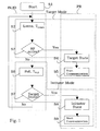
- Fig. 1 is a schematical flow chart of a preferred embodiment of the inventive method for operating a near field communication system 10. It is majorly built up by an initialization section IN and a processing section.
- the initialization section IN serves to prepare for, enable and establish a near field communication an comprises an idle process ID in which a given near field communication device 21, 22 either searches in the target operational mode or target mode as a potential target device T for a potential initiator device I by listening for a RF signal - according to steps S2 and S3 - or as a potential initiator device or initiator I in the initiator operational mode or initiator mode sends out a RF signal in order to search for a potential target device or target T - according to steps S6 and S7.
- the processing section PR comprises the near field communication processes S5 and S9 as such.
- step S4 The target operational state of step S4 is entered by a potential target device T if during the period of time T Listen of searching or listening for a potential initiator's RF signal such a RF signal is received.
- step S8 The initiator operational state of step S8 is entered by a potential initiator device I if during the period of time T Poll of polling for a potential target's RF signal reception such a RF signal sink is found.
- the period of time T Listen of searching or listening for a potential initiator's RF signal is also referred to as the) period of time t target for operating a respective participating near field communication device 21, 22 in the idle process ID in the target operational state or mode.
- the period of time T Poll of polling for a potential target's RF signal reception is also referred to as the period of time t initiator for operating a respective participating near field communication device 21, 22 in the idle process ID in the initiator operational state or mode.
- Fig. 4 is a schematical block diagram which demonstrates the typical near field communication situation and a respective near field communication system 10.
- the near field communication system 10 shown in Fig. 4 comprises a first near field communication device 21 which is assigned to be an initiator device I and a second near field communication device 22 which is assigned to be a target device T.
- further near field communication devices 23 are present.
- the further devices 23 are situated outside the communication areas CAI and CA2 of the initiator device 1, 21 and the target device T, 22, respectively. Therefore, the further devices 23 are not capable of contributing to the system 10 and to its communication. Only the target device T, 22 and the initiator device I. 21 lie within the communication areas CAI and CA2, respectively.
Claims (15)
- Verfahren zum Betrieb eines Nahfeldkommunikationssystems mindestens einer ersten und einer zweiten teilnehmenden Nahfeldkommunikationsvorrichtung (21, 22),
wobei für jede teilnehmende Nahfeldkommunikationsvorrichtung (21, 22), ein Lehrlaufprozess (ID) durchgeführt wird, indem wiederholt der Betriebsmodus der jeweiligen teilnehmenden Nahfeldkommunikationsvorrichtungen gewechselt wird zwischen
einem Zielbetriebsmodus (SM), in dem die jeweilige teilnehmende Nahfeldkommunikationsvorrichtung (21, 22) durch Horchen nach einem HF-Signal nach einer potentiellen Initiatorvorrichtung sucht, und
einem Initiator-Betriebsmodus (IM), in dem die jeweilige teilnehmende Nahfeldkommunikationsvorrichtung (21, 22) ein HF-Signal aussendet, um nach einer potentiellen Zielvorrichtung zu suchen, bis Kommunikation zwischen der jeweiligen teilnehmenden Nahfeldkommunikationsvorrichtung (21, 22) und einer anderen teilnehmenden Nahfeldkommunikationsvorrichtung (22, 21) hergestellt ist. - Verfahren nach Anspruch 1,
mit einem Initialisierungsteil (IN) für jede der teilnehmenden Nahfeldkommunikationsvorrichtungen (21, 22), um zu versuchen, eine Verbindung und eine Kommunikation zwischen einer jeweiligen teilnehmenden Nahfeldkommunikationsvorrichtung (21, 22) und einer anderen der teilnehmenden Nahfeldkommunikationsvorrichtung (22, 21) herzustellen und aufzubauen,
wobei der Lehrlaufprozess (ID) für jede jeweilige teilnehmende Nahfeldkommunikationsvorrichtung (21, 22) ein Teil des jeweiligen Initialisierungsteils (IN) ist. - Verfahren nach einem der vorhergehenden Ansprüche,
wobei Zeiträume (ttarget,tinitiator) zum Betrieb einer jeweiligen teilnehmenden Nahfeldkommunikationsvorrichtung (21, 22) in dem Lehrlaufprozess (ID) im Zielbetriebsmodus bzw. im Initiator-Betriebsmodus jeder der teilnehmenden Nahfeldkommunikationsvorrichtungen (21, 22) vorbestimmt oder während des Betriebs erzeugt werden. - Verfahren nach Anspruch 3,
wobei die Zeiträume (ttarget, tinitiator) zum Betrieb einer jeweiligen teilnehmenden Nahfeldkommunikationsvorrichtung (21, 22) in dem Lehrlaufprozess (ID) im Zielbetriebsmodus und im Initiator-Betriebsmodus für verschiedene teilnehmende Nahfeldkommunikationsvorrichtungen (21, 22) verschieden sind. - Verfahren nach einem der vorhergehenden Ansprüche 3 oder 4,
wobei die Zeiträume (ttarget, tinitiator) zum Betrieb einer jeweiligen teilnehmenden Nahfeldkommunikationsvorrichtung (21, 22) in dem Lehrlaufprozess (ID) im Zielbetriebsmodus und im Initiator-Betriebsmodus für eine gegebene teilnehmende Nahfeldkommunikationsvorrichtung (21, 22) verschieden sind. - Verfahren nach einem der vorhergehenden Ansprüche 3 bis 5,
wobei der Zeitraum (tinitiator) zum Betrieb einer gegebenen teilnehmenden Nahfeldkommunikationsvorrichtung (21, 22) im Initiator-Betriebsmodus kürzer als der Zeitraum (ttarget) zum Betrieb der jeweiligen teilnehmenden Nahfeldkommunikationsvorrichtung (21, 22 im Zielbetriebsmodus ist, um Energie zu sparen. - Verfahren nach einem der vorhergehenden Ansprüche 3 bis 6,
wobei der Zeitraum (tinitiator) zum Betrieb einer gegebenen teilnehmenden Nahfeldkommunikationsvorrichtung (21, 22) in dem Initiator-Betriebsmodus ein randomisierter Wert mit einer festen Komponente (tinitiator,fix) und einer zufälligen Komponente (tinitiator,random) ist. - Verfahren nach einem der vorhergehenden Ansprüche 3 bis 7,
wobei der Zeitraum (ttarget) zum Betrieb einer gegebenen teilnehmenden Nahfeldkommunikationsvorrichtung (21, 22) in dem Zielbetriebsmodus ein randomisierter Wert mit einer festen Komponente (ttarget,fix) und einer zufälligen Komponente (ttarget,random) ist. - Verfahren nach einem der vorhergehenden Ansprüche,
wobei für jede teilnehmende Nahfeldkommunikationsvorrichtung (21, 22) der jeweilige Lehrlaufprozess (ID) mit Betrieb der jeweiligen teilnehmenden Nahfeldkommunikationsvorrichtung (21, 22) in dem Initiator-Betriebsmodus begonnen wird. - Verfahren nach einem der vorhergehenden Ansprüche,
wobei für jede teilnehmende Nahfeldkommunikationsvorrichtung (21, 22) der jeweilige Lehrlaufprozess (ID) mit Betrieb der jeweiligen teilnehmenden Nahfeldkommunikationsvorrichtung (21, 22) in dem Zielbetriebsmodus begonnen wird. - Verfahren nach einem der vorhergehenden Ansprüche,
wobei für jede der teilnehmenden Nahfeldkommunikationsvorrichtungen (21, 22) der Lehrlaufprozess (ID) für eine jeweilige teilnehmende Nahfeldkommunikationsvorrichtung (21, 22) mit einem zufällig gewählten Betriebsmodus begonnen wird, der aus der Gruppe bestehend aus dem Initiator-Betriebsmodus und dem Zielbetriebsmodus ausgewählt wird. - Verfahren nach einem der vorhergehenden Ansprüche,
wobei der Lehrlaufprozess durchgeführt wird, bis eine Unterbrechungsbedingung erfüllt ist. - System, umfassend:eine erste teilnehmende Nahfeldkommunikationsvorrichtung (21) und eine zweite teilnehmende Nahfeldkommunikationsvorrichtung (22), die jeweils dafür ausgelegt sind, einen Lehrlaufprozess durchzuführen,wobei der Lehrlaufprozess Folgendes umfasst:Wechseln des Betriebsmodus der jeweiligen teilnehmenden Nahfeldkommunikationsvorrichtungen (21, 22) zwischen einem Zielbetriebsmodus (SM), in dem die jeweilige teilnehmende Nahfeldkommunikationsvorrichtung (21, 22) durch Horchen nach einem HF-Signal nach einer potentiellen Initiatorvorrichtung sucht, und einem Initiator-Betriebsmodus (IM), in dem die jeweilige teilnehmende Nahfeldkommunikationsvorrichtung (21, 22) ein HF-Signal aussendet, um nach einer potentiellen Zielvorrichtung zu suchen, bis Kommunikation zwischen der jeweiligen teilnehmenden Nahfeldkommunikationsvorrichtung (21, 22) und einer anderen teilnehmenden Nahfeldkommunikationsvorrichtung (22, 21) hergestellt wird.
- Nahfeldkommunikationsvorrichtung (21, 22), wobei
die Nahfeldkommunikationsvorrichtung (21, 22) ausgelegt ist zum Durchführen eines Lehrlaufprozesses (ID) durch wiederholtes Wechseln des Betriebsmodus der jeweiligen teilnehmenden Nahfeldkommunikationsvorrichtungen (21, 22) zwischen einem Zielbetriebsmodus (SM), in dem die jeweilige teilnehmende Nahfeldkommunikationsvorrichtung (21, 22) durch Horchen nach einem HF-Signal nach einer potentiellen Initiatorvorrichtung sucht und einem Initiator-Betriebsmodus (IM), in dem die jeweilige teilnehmende Nahfeldkommunikationsvorrichtung (21, 22) ein HF-Signal aussendet, um nach einer potentiellen Zielvorrichtung zu suchen, bis Kommunikation zwischen der jeweiligen teilnehmenden Nahfeldkommunikationsvorrichtung (21, 22) und einer anderen teilnehmenden Nahfeldkommunikationsvorrichtung (22, 21) hergestellt wird. - Computerprogrammprodukt, das ein computerlesbares Speichermedium umfasst, das Anweisungen speichert, die durch einen Prozessor ausführbar sind, um die Schritte des Verfahrens zum Betrieb eines Nahfeldkommunikationssystems nach einem der vorhergehenden Ansprüche 1 bis 12 auszuführen.
Priority Applications (11)
| Application Number | Priority Date | Filing Date | Title |
|---|---|---|---|
| EP14003708.6A EP2840717B1 (de) | 2004-10-29 | 2004-10-29 | Verfahren zum Betrieb eines Nahfeldkommunikationssystems |
| EP04025775.0A EP1653632B1 (de) | 2004-10-29 | 2004-10-29 | Verfahren zum Betrieb eines Nahfeld-Kommunikationssystems |
| EP16201192.8A EP3154206A1 (de) | 2004-10-29 | 2004-10-29 | Verfahren zum betrieb eines nahfeldkommunikationssystems |
| AU2005202287A AU2005202287A1 (en) | 2004-10-29 | 2005-05-26 | Method for operating a near field communication system |
| CA002509018A CA2509018A1 (en) | 2004-10-29 | 2005-06-02 | Method for operating a near field communication system |
| TW094118916A TWI362006B (en) | 2004-10-29 | 2005-06-08 | Method for operating a near field communication system |
| BRPI0503048-0A BRPI0503048A (pt) | 2004-10-29 | 2005-07-28 | método para operar um sistema de comunicação de campo próximo, sistema ou aparelho, dispositivo de comunicação de campo próximo, produto de programa de computação, e, meio de armazenamento legìvel por computador |
| US11/260,132 US7734307B2 (en) | 2004-10-29 | 2005-10-27 | Method for operating a near field communication system |
| KR1020050102188A KR101168433B1 (ko) | 2004-10-29 | 2005-10-28 | 근거리 무선 통신 시스템을 구동하기 위한 방법 |
| CN200510118822.0A CN1767409B (zh) | 2004-10-29 | 2005-10-28 | 操作近场通信系统的方法 |
| JP2005316080A JP2006129498A (ja) | 2004-10-29 | 2005-10-31 | 近距離無線通信システムの動作方法 |
Applications Claiming Priority (1)
| Application Number | Priority Date | Filing Date | Title |
|---|---|---|---|
| EP04025775.0A EP1653632B1 (de) | 2004-10-29 | 2004-10-29 | Verfahren zum Betrieb eines Nahfeld-Kommunikationssystems |
Related Child Applications (3)
| Application Number | Title | Priority Date | Filing Date |
|---|---|---|---|
| EP16201192.8A Division EP3154206A1 (de) | 2004-10-29 | 2004-10-29 | Verfahren zum betrieb eines nahfeldkommunikationssystems |
| EP14003708.6A Division EP2840717B1 (de) | 2004-10-29 | 2004-10-29 | Verfahren zum Betrieb eines Nahfeldkommunikationssystems |
| EP14003708.6A Division-Into EP2840717B1 (de) | 2004-10-29 | 2004-10-29 | Verfahren zum Betrieb eines Nahfeldkommunikationssystems |
Publications (2)
| Publication Number | Publication Date |
|---|---|
| EP1653632A1 EP1653632A1 (de) | 2006-05-03 |
| EP1653632B1 true EP1653632B1 (de) | 2014-12-17 |
Family
ID=34927165
Family Applications (3)
| Application Number | Title | Priority Date | Filing Date |
|---|---|---|---|
| EP04025775.0A Expired - Fee Related EP1653632B1 (de) | 2004-10-29 | 2004-10-29 | Verfahren zum Betrieb eines Nahfeld-Kommunikationssystems |
| EP16201192.8A Withdrawn EP3154206A1 (de) | 2004-10-29 | 2004-10-29 | Verfahren zum betrieb eines nahfeldkommunikationssystems |
| EP14003708.6A Expired - Fee Related EP2840717B1 (de) | 2004-10-29 | 2004-10-29 | Verfahren zum Betrieb eines Nahfeldkommunikationssystems |
Family Applications After (2)
| Application Number | Title | Priority Date | Filing Date |
|---|---|---|---|
| EP16201192.8A Withdrawn EP3154206A1 (de) | 2004-10-29 | 2004-10-29 | Verfahren zum betrieb eines nahfeldkommunikationssystems |
| EP14003708.6A Expired - Fee Related EP2840717B1 (de) | 2004-10-29 | 2004-10-29 | Verfahren zum Betrieb eines Nahfeldkommunikationssystems |
Country Status (9)
| Country | Link |
|---|---|
| US (1) | US7734307B2 (de) |
| EP (3) | EP1653632B1 (de) |
| JP (1) | JP2006129498A (de) |
| KR (1) | KR101168433B1 (de) |
| CN (1) | CN1767409B (de) |
| AU (1) | AU2005202287A1 (de) |
| BR (1) | BRPI0503048A (de) |
| CA (1) | CA2509018A1 (de) |
| TW (1) | TWI362006B (de) |
Families Citing this family (51)
| Publication number | Priority date | Publication date | Assignee | Title |
|---|---|---|---|---|
| US8352323B2 (en) * | 2007-11-30 | 2013-01-08 | Blaze Mobile, Inc. | Conducting an online payment transaction using an NFC enabled mobile communication device |
| US8081060B1 (en) | 2006-05-12 | 2011-12-20 | Nokia Corporation | System and method for communications establishment |
| US8102797B2 (en) * | 2006-08-17 | 2012-01-24 | Microsoft Corporation | Web format-based wireless communications |
| US7958291B2 (en) * | 2006-10-10 | 2011-06-07 | Atmel Rousset S.A.S. | Supplemental communication interface |
| US7756467B2 (en) * | 2006-12-01 | 2010-07-13 | Sony Ericsson Mobile Communications Ab | Multimedia distribution using a near field communication capable wireless communication device |
| US7734299B2 (en) * | 2007-03-20 | 2010-06-08 | Microsoft Corporation | Facilitating use of a device based on short-range wireless technology |
| US7845568B2 (en) * | 2007-05-09 | 2010-12-07 | Atmel Rousset S.A.S. | Managing power and timing in a smart card device |
| US8400913B2 (en) * | 2007-05-23 | 2013-03-19 | Microsoft Corporation | Method for optimizing near field links |
| JP4533404B2 (ja) * | 2007-05-24 | 2010-09-01 | 日立オートモティブシステムズ株式会社 | エンジン制御装置 |
| JP4552158B2 (ja) | 2008-07-09 | 2010-09-29 | ソニー株式会社 | 通信装置 |
| US8850052B2 (en) * | 2008-09-30 | 2014-09-30 | Apple Inc. | System and method for simplified resource sharing |
| JP4720899B2 (ja) * | 2008-11-27 | 2011-07-13 | ソニー株式会社 | 通信装置、通信方法、プログラム、および通信システム |
| WO2010077194A1 (en) * | 2008-12-29 | 2010-07-08 | Telefonaktiebolaget L M Ericsson (Publ) | Method and device for installing applications on nfc-enabled devices |
| JP5293271B2 (ja) * | 2009-02-27 | 2013-09-18 | ソニー株式会社 | 無線通信装置、情報処理装置、無線通信方法及び情報処理システム |
| JP4599449B2 (ja) * | 2009-04-15 | 2010-12-15 | 株式会社東芝 | 電子機器及び通信制御方法 |
| ES2782120T3 (es) | 2010-01-14 | 2020-09-10 | France Brevets | Dispositivo electrónico y método de funcionamiento del mismo |
| JP5609202B2 (ja) * | 2010-03-26 | 2014-10-22 | カシオ計算機株式会社 | 端末装置及びプログラム |
| JP5056884B2 (ja) * | 2010-03-26 | 2012-10-24 | カシオ計算機株式会社 | 通信装置及び通信制御プログラム |
| US8718546B2 (en) | 2010-08-16 | 2014-05-06 | Blackberry Limited | Near-field communication (NFC) system providing low power peer-to-peer recognition mode and related methods |
| US8787830B2 (en) | 2010-08-16 | 2014-07-22 | Blackberry Limited | Near-field communication (NFC) system providing low power mode frequency cycling and related methods |
| US20120045989A1 (en) * | 2010-08-18 | 2012-02-23 | Nokia Corporation | Device discovery in near-field communication |
| US8068011B1 (en) | 2010-08-27 | 2011-11-29 | Q Street, LLC | System and method for interactive user-directed interfacing between handheld devices and RFID media |
| US9390298B2 (en) * | 2010-11-17 | 2016-07-12 | Blackberry Limited | Application routing configuration for NFC controller supporting multiple NFCEEs |
| WO2012093773A2 (ko) | 2011-01-04 | 2012-07-12 | 에이큐 주식회사 | 광고 정보 제공 시스템 |
| EP2506448B1 (de) * | 2011-03-28 | 2021-08-04 | Sony Group Corporation | Verfahren und Modul zum Schalten des Betriebsmodus und Endgerätausrüstung |
| CN102710296A (zh) * | 2011-03-28 | 2012-10-03 | 索尼爱立信移动通讯有限公司 | 工作模式切换方法、工作模式切换模块和终端设备 |
| US20120252361A1 (en) * | 2011-03-31 | 2012-10-04 | Nxp B.V. | Wireless data transfer |
| US8171137B1 (en) | 2011-05-09 | 2012-05-01 | Google Inc. | Transferring application state across devices |
| US8224894B1 (en) | 2011-05-09 | 2012-07-17 | Google Inc. | Zero-click sharing of application context across devices |
| US8812601B2 (en) * | 2011-05-09 | 2014-08-19 | Google Inc. | Transferring application state across devices with checkpoints |
| US8824961B2 (en) * | 2011-06-28 | 2014-09-02 | Broadcom Corporation | Method and apparatus for reducing NFC multi-protocol polling duration and power consumption |
| US8686887B2 (en) * | 2011-10-26 | 2014-04-01 | Qualcomm Incorporated | NFC transceiver with current converter |
| US9466877B2 (en) | 2011-11-29 | 2016-10-11 | Hill-Rom Services, Inc. | Hospital bed having near field communication capability |
| US8942623B2 (en) * | 2011-12-02 | 2015-01-27 | Qualcomm Incorporated | Reducing NFC peer mode connection times |
| US9374134B2 (en) | 2012-02-02 | 2016-06-21 | Qualcomm Incorporated | Methods and apparatus for improving the identification of multiple NFC-A devices |
| US9054750B2 (en) | 2012-04-23 | 2015-06-09 | Qualcomm Incorporated | Methods and apparatus for improving RF discovery for peer mode communications |
| US8923761B2 (en) | 2012-05-17 | 2014-12-30 | Qualcomm Incorporated | Methods and apparatus for improving NFC RF discovery loop tuning based on device sensor measurements |
| US9331744B2 (en) | 2012-05-18 | 2016-05-03 | Qualcomm Incorporated | Methods and apparatus for improving collision resolution among multiple NFC-A devices |
| US9184800B2 (en) | 2012-07-16 | 2015-11-10 | Google Inc. | Automated sharing of application data over a near field communication link |
| US9071926B2 (en) | 2012-10-22 | 2015-06-30 | Qualcomm Incorporated | Device detection using load modulation in near-field communications |
| US9125180B1 (en) | 2013-03-15 | 2015-09-01 | Google Inc. | Techniques for automatically establishing a long-lasting connection across computing devices configured for short-range wireless communication |
| WO2015015916A1 (ja) * | 2013-07-31 | 2015-02-05 | ソニー株式会社 | 情報処理装置、情報処理方法、プログラム、および情報処理システム |
| US20150091496A1 (en) * | 2013-10-01 | 2015-04-02 | Blackberry Limited | Bi-directional communication with a device under charge |
| US20150169039A1 (en) * | 2013-12-16 | 2015-06-18 | Kabushiki Kaisha Toshiba | Electronic Apparatus, Method and Storage Medium |
| JP6109771B2 (ja) * | 2014-03-13 | 2017-04-05 | 株式会社東芝 | ファイル送受信装置およびファイル送受信方法 |
| FR3020907A1 (fr) * | 2014-05-07 | 2015-11-13 | St Microelectronics Int Nv | Procede pour deceler plusieurs dispositifs nfc-b par un lecteur nfc-b et lecteur nfc-b correspondant |
| JP6420584B2 (ja) * | 2014-07-30 | 2018-11-07 | キヤノン株式会社 | 通信装置、通信装置の制御方法およびプログラム |
| CN107623551B (zh) * | 2016-07-13 | 2021-08-06 | 意法半导体国际有限公司 | 用于检测邻近有源近场通信设备的方法及电路装置 |
| JP6915514B2 (ja) * | 2017-11-30 | 2021-08-04 | ブラザー工業株式会社 | 通信装置 |
| AT523859A1 (de) * | 2020-06-03 | 2021-12-15 | Res Industrial Systems Engineering Rise Forschungs Entwicklungs Und Grossprojektberatung Gmbh | Verfahren zum Kommunikationsaufbau zwischen einem Transaktionsterminal und einem mobilen Gerät unter Vermeidung eines automatischen Starts einer Applikation |
| CN117395639A (zh) * | 2023-12-12 | 2024-01-12 | 荣耀终端有限公司 | 设备寻找方法及电子设备 |
Family Cites Families (13)
| Publication number | Priority date | Publication date | Assignee | Title |
|---|---|---|---|---|
| US3968435A (en) * | 1975-02-06 | 1976-07-06 | Stover Harris A | Communication system |
| US5437057A (en) * | 1992-12-03 | 1995-07-25 | Xerox Corporation | Wireless communications using near field coupling |
| GB2279536B (en) * | 1993-06-19 | 1997-01-29 | Coal Ind | Electronic apparatus and methods for electromagnetic communications |
| US5832390A (en) * | 1996-07-03 | 1998-11-03 | Ericsson, Inc. | Untethered microphone and base unit |
| KR100677078B1 (ko) * | 1999-11-26 | 2007-02-01 | 삼성전자주식회사 | 블루투스 장착 기기간 네트워크 운영 방법 |
| KR100436756B1 (ko) * | 2001-08-31 | 2004-06-23 | 삼성전자주식회사 | 스니프모드에서 상호간의 데이터통신 시간을 절약할 수있는 무선통신 시스템 |
| US7313678B2 (en) * | 2003-03-05 | 2007-12-25 | Broadcom Corporation | Installation procedure for wireless human interface device |
| JP2004215225A (ja) * | 2002-12-17 | 2004-07-29 | Sony Corp | 通信システムおよび通信方法、並びにデータ処理装置 |
| US7020474B2 (en) * | 2003-06-25 | 2006-03-28 | Cross Match Technologies, Inc. | System and method for securing short-distance wireless communications, and applications thereof |
| US7194261B2 (en) * | 2003-08-21 | 2007-03-20 | Motorola, Inc. | Method and apparatus for facilitating data transmissions |
| US7061428B1 (en) * | 2004-07-29 | 2006-06-13 | Remote Play, Inc. | Frequency hopping range estimation with low power consumption |
| US20070026825A1 (en) * | 2005-02-24 | 2007-02-01 | Innovision Research & Technology Plc | NFC device and apparatus |
| US7546149B2 (en) * | 2005-03-08 | 2009-06-09 | Motorola, Inc. | Deep sleep mode for portable communication device |
-
2004
- 2004-10-29 EP EP04025775.0A patent/EP1653632B1/de not_active Expired - Fee Related
- 2004-10-29 EP EP16201192.8A patent/EP3154206A1/de not_active Withdrawn
- 2004-10-29 EP EP14003708.6A patent/EP2840717B1/de not_active Expired - Fee Related
-
2005
- 2005-05-26 AU AU2005202287A patent/AU2005202287A1/en not_active Abandoned
- 2005-06-02 CA CA002509018A patent/CA2509018A1/en not_active Abandoned
- 2005-06-08 TW TW094118916A patent/TWI362006B/zh not_active IP Right Cessation
- 2005-07-28 BR BRPI0503048-0A patent/BRPI0503048A/pt not_active Application Discontinuation
- 2005-10-27 US US11/260,132 patent/US7734307B2/en not_active Expired - Fee Related
- 2005-10-28 CN CN200510118822.0A patent/CN1767409B/zh not_active Expired - Fee Related
- 2005-10-28 KR KR1020050102188A patent/KR101168433B1/ko active IP Right Grant
- 2005-10-31 JP JP2005316080A patent/JP2006129498A/ja not_active Withdrawn
Also Published As
| Publication number | Publication date |
|---|---|
| EP3154206A1 (de) | 2017-04-12 |
| CN1767409B (zh) | 2012-02-15 |
| EP2840717A1 (de) | 2015-02-25 |
| TW200614083A (en) | 2006-05-01 |
| US20060094356A1 (en) | 2006-05-04 |
| EP1653632A1 (de) | 2006-05-03 |
| CN1767409A (zh) | 2006-05-03 |
| AU2005202287A1 (en) | 2006-05-18 |
| US7734307B2 (en) | 2010-06-08 |
| KR101168433B1 (ko) | 2012-07-25 |
| BRPI0503048A (pt) | 2006-06-27 |
| JP2006129498A (ja) | 2006-05-18 |
| EP2840717B1 (de) | 2017-02-01 |
| CA2509018A1 (en) | 2006-04-29 |
| KR20060052306A (ko) | 2006-05-19 |
| TWI362006B (en) | 2012-04-11 |
Similar Documents
| Publication | Publication Date | Title |
|---|---|---|
| EP1653632B1 (de) | Verfahren zum Betrieb eines Nahfeld-Kommunikationssystems | |
| CN101233699B (zh) | 一种执行近场通信的方法和设备 | |
| US10721606B2 (en) | Mobile terminal and method involving near field communication | |
| EP2080350B1 (de) | Verbindungslose informationsübertragung von einer werbevorrichtung | |
| KR101054717B1 (ko) | 전자 근거리 무선통신이 가능한 다기능 장치와 그 동작방법 | |
| US7643798B2 (en) | Passive NFC activation of short distance wireless communication | |
| TWI444069B (zh) | 通訊裝置與多層次傳輸功率控制方法 | |
| US8619666B2 (en) | Wireless communications system and wireless communications device | |
| US20090234728A1 (en) | Advertising introductory information including multiple profiles | |
| Yu et al. | Reducing reader collision for mobile RFID | |
| CN113170377A (zh) | 一种网络连接建立方法及相应的装置 | |
| CN111343614B (zh) | 一种面向ble主动扫描的快速发现方法 | |
| US10212576B2 (en) | Near field communication device | |
| JP2000049654A (ja) | Rfidシステム | |
| WO2010046732A1 (en) | Feature selection in wireless communication | |
| US20230199872A1 (en) | Efficient procedures to create bluetooth le central connection on an advertiser | |
| KR101870645B1 (ko) | 근거리 무선 통신 장치 | |
| JP2005057601A (ja) | 無線端末及び無線通信方法 |
Legal Events
| Date | Code | Title | Description |
|---|---|---|---|
| PUAI | Public reference made under article 153(3) epc to a published international application that has entered the european phase |
Free format text: ORIGINAL CODE: 0009012 |
|
| AK | Designated contracting states |
Kind code of ref document: A1 Designated state(s): AT BE BG CH CY CZ DE DK EE ES FI FR GB GR HU IE IT LI LU MC NL PL PT RO SE SI SK TR |
|
| AX | Request for extension of the european patent |
Extension state: AL HR LT LV MK |
|
| 17P | Request for examination filed |
Effective date: 20061013 |
|
| AKX | Designation fees paid |
Designated state(s): DE FR GB |
|
| RAP1 | Party data changed (applicant data changed or rights of an application transferred) |
Owner name: SONY DEUTSCHLAND GMBH |
|
| 17Q | First examination report despatched |
Effective date: 20080908 |
|
| REG | Reference to a national code |
Ref country code: DE Ref legal event code: R079 Ref document number: 602004046327 Country of ref document: DE Free format text: PREVIOUS MAIN CLASS: H04B0005020000 Ipc: G06K0007000000 |
|
| GRAP | Despatch of communication of intention to grant a patent |
Free format text: ORIGINAL CODE: EPIDOSNIGR1 |
|
| RIC1 | Information provided on ipc code assigned before grant |
Ipc: G06K 7/10 20060101ALI20140612BHEP Ipc: G06K 7/00 20060101AFI20140612BHEP Ipc: H04B 5/02 20060101ALI20140612BHEP |
|
| INTG | Intention to grant announced |
Effective date: 20140703 |
|
| GRAS | Grant fee paid |
Free format text: ORIGINAL CODE: EPIDOSNIGR3 |
|
| GRAA | (expected) grant |
Free format text: ORIGINAL CODE: 0009210 |
|
| AK | Designated contracting states |
Kind code of ref document: B1 Designated state(s): DE FR GB |
|
| REG | Reference to a national code |
Ref country code: GB Ref legal event code: FG4D |
|
| REG | Reference to a national code |
Ref country code: DE Ref legal event code: R096 Ref document number: 602004046327 Country of ref document: DE Effective date: 20150212 |
|
| REG | Reference to a national code |
Ref country code: DE Ref legal event code: R097 Ref document number: 602004046327 Country of ref document: DE |
|
| PLBE | No opposition filed within time limit |
Free format text: ORIGINAL CODE: 0009261 |
|
| REG | Reference to a national code |
Ref country code: FR Ref legal event code: PLFP Year of fee payment: 12 |
|
| STAA | Information on the status of an ep patent application or granted ep patent |
Free format text: STATUS: NO OPPOSITION FILED WITHIN TIME LIMIT |
|
| 26N | No opposition filed |
Effective date: 20150918 |
|
| REG | Reference to a national code |
Ref country code: FR Ref legal event code: PLFP Year of fee payment: 13 |
|
| REG | Reference to a national code |
Ref country code: FR Ref legal event code: PLFP Year of fee payment: 14 |
|
| REG | Reference to a national code |
Ref country code: FR Ref legal event code: PLFP Year of fee payment: 15 |
|
| PGFP | Annual fee paid to national office [announced via postgrant information from national office to epo] |
Ref country code: FR Payment date: 20201021 Year of fee payment: 17 Ref country code: GB Payment date: 20201022 Year of fee payment: 17 Ref country code: DE Payment date: 20201022 Year of fee payment: 17 |
|
| REG | Reference to a national code |
Ref country code: DE Ref legal event code: R119 Ref document number: 602004046327 Country of ref document: DE |
|
| GBPC | Gb: european patent ceased through non-payment of renewal fee |
Effective date: 20211029 |
|
| PG25 | Lapsed in a contracting state [announced via postgrant information from national office to epo] |
Ref country code: GB Free format text: LAPSE BECAUSE OF NON-PAYMENT OF DUE FEES Effective date: 20211029 Ref country code: DE Free format text: LAPSE BECAUSE OF NON-PAYMENT OF DUE FEES Effective date: 20220503 |
|
| PG25 | Lapsed in a contracting state [announced via postgrant information from national office to epo] |
Ref country code: FR Free format text: LAPSE BECAUSE OF NON-PAYMENT OF DUE FEES Effective date: 20211031 |