EP1653446A2 - Modularer Magnetkopf zur Abtastung magnetisierter Bänder oder Fäden - Google Patents
Modularer Magnetkopf zur Abtastung magnetisierter Bänder oder Fäden Download PDFInfo
- Publication number
- EP1653446A2 EP1653446A2 EP05110115A EP05110115A EP1653446A2 EP 1653446 A2 EP1653446 A2 EP 1653446A2 EP 05110115 A EP05110115 A EP 05110115A EP 05110115 A EP05110115 A EP 05110115A EP 1653446 A2 EP1653446 A2 EP 1653446A2
- Authority
- EP
- European Patent Office
- Prior art keywords
- core
- modular
- end edge
- magnetic head
- cores
- Prior art date
- Legal status (The legal status is an assumption and is not a legal conclusion. Google has not performed a legal analysis and makes no representation as to the accuracy of the status listed.)
- Granted
Links
Images

Classifications
-
- G—PHYSICS
- G07—CHECKING-DEVICES
- G07D—HANDLING OF COINS OR VALUABLE PAPERS, e.g. TESTING, SORTING BY DENOMINATIONS, COUNTING, DISPENSING, CHANGING OR DEPOSITING
- G07D7/00—Testing specially adapted to determine the identity or genuineness of valuable papers or for segregating those which are unacceptable, e.g. banknotes that are alien to a currency
- G07D7/04—Testing magnetic properties of the materials thereof, e.g. by detection of magnetic imprint
Definitions
- the present invention relates to a magnetic head of the type defined in the preamble of claim 1.
- the magnetic head is intended for scanning a code stored on a strip of magnetic material, in particular - but not exclusively - a security thread incorporated within a banknote.
- a security thread is disposed perpendicularly to a major side of a banknote, and extends for the entire width of the banknote, parallel to a minor side thereof.
- a known type of magnetic security thread is composed of a support strip which may be made of a flexible and impermeable plastics material, on which are deposited some areas of magnetic material such as, for example, iron oxides.
- a different amount of magnetic material is applied in the various zones of the thread, varying the thickness, the density or the extent of the area occupied.
- Modern devices for verifying the authenticity of banknotes are generally provided with feed means for feeding a banknote in a direction substantially perpendicular to the magnetic security thread, and with a scanning head comprising a "gap" which constitutes the sensitive part of the head, for scanning the code stored in the security thread.
- a magnetic head of known type comprises a core of magnetic material in the shape of an open ring composed of a pair of half-cores constituted by two profile sections of ferromagnetic metal sheet, elongate in a longitudinal direction and having substantially C-shaped opposed cross-sections; the rearward end edges are physically in contact in order to have magnetic continuity between the two half-cores.
- the forward end edges however are spaced by means of the insertion of a thin sheet of magnetically non-conductive material (e.g. copper), so that the two half-cores together constitute a ring magnetically opened in its forward part by a longitudinal gap which constitutes the sensitive part of the head.
- each half-core is overmoulded a covering of electrically insulating material, and round this is wound a coil, the heads of which are connected to respective PINs disposed at the bottom.
- the whole constituted by the core and windings is immersed in a synthetic resin within a screening container made of permalloy, so that only the forward surface of the head, which has the gap, emerges from the screen.
- the passage of a magnetic security thread which moves perpendicularly to the gap generates, by magnetic induction, an electrical voltage in the coils which is made available at the PINs.
- magnetic heads have been constructed by assembling two half-cores having a length corresponding to that of the head. This involves significant investment, since it is necessary each time to provide a different die for the shearing and bending of the sheets of the half-cores, and a different mould for overmoulding the layer of plastics material capable of electrically insulating the half-cores from the respective windings.
- the problem is particularly acute in the field of devices for verifying the authenticity of banknotes, where it is necessary to construct heads which are different each time because of the range defined by the various positions which the security thread assumes within banknotes of different sizes.
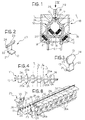
- the core of a magnetic head 10 comprises a pair of half-cores, right 11 and left 12, that are elongate in a direction defined here as longitudinal and facing one another in a transverse direction.
- the two half-cores have substantially C-shaped opposed cross-sections, with respective rearward edges 13, 14, in contact, and respective forward edges 15, 16 separated by a thin strip 17 of magnetically non-conductive material.
- the references 18, 19 indicate coils wound round the half-cores and electrically insulated therefrom by means of bodies of plastics material, as described in detail hereinafter.
- each half-core is composed of a plurality of modular half-core elements 20 longitudinally side by side with one another.
- each modular element 20 has a substantially C-shaped cross-section, with a rearward portion 21 extending in a transverse direction with a free end edge 13 intended to contact the free end edge 14 of an opposed identical modular element 20 forming part of the opposed half-core, an intermediate portion 22, substantially perpendicular to the rearward portion 21, and a forward portion 23 having a part 24 protruding longitudinally from one side with respect to the intermediate portion 22.
- the forward portion 23 is therefore asymmetric ( Figure 3) with respect to a transverse plane which passes centrally through the rearward portion 21 and intermediate portion 22.
- Figure 4 illustrates diagrammatically the arrangement assumed by the modular elements 20 in the head, once assembled. Due to the shape of the modular elements 20, when two of these elements 20a, 20b, each belonging to a different half-core, are opposed in such a way as to align transversely the rearward edges 13, 14 in contact with one another, the protruding part 24 of one of the two elements (20a) protrudes in the opposed longitudinal direction with respect to the protruding part 24 of the other element 20b.
- the forward portions 23 of the modular elements of a half-core 11 are longitudinally staggered, preferably by half a pitch, with respect to the forward portions 23 of the modular elements of the other half-core 12.
- Each pair of modular elements 20a, 20b transversely fitted side by side constitutes an open ring section of the core of the head.
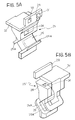
- each modular element 20 is inserted and partially received in a support of plastics material 25 forming a tubular portion 26 (of rectangular section in the example illustrated) which contains within it the intermediate portion 22 and/or the rearward portion 21 of a modular element 20.
- a support of plastics material 25 forming a tubular portion 26 (of rectangular section in the example illustrated) which contains within it the intermediate portion 22 and/or the rearward portion 21 of a modular element 20.
- One of the supports 25 is illustrated separately in Figures 5A and 5B.
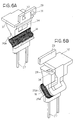
- Round the tubular portion 26 is wound a coil 18 (or 19) the heads of which are electrically connected to connecting PINs 27 protruding from the rearward part of the head ( Figures 6A, 6B and 7A, 7B).
- each support 25 is of modular type and has lateral connection means and seats 28 in the shape of small recesses and protuberances for being coupled mechanically to two like supports longitudinally adjacent on opposite sides and capable of supporting modular elements 20 belonging to the same half-core, and further front connection means and seats 30, 31, in the shape of small recesses and protuberances for mechanical coupling to a transversely adjacent support which supports a modular element 20 belonging to the other half-core.
- the forward part of each support 25 forms a horizontal plate portion 32 longitudinally staggered with respect to the main body of the support, such as to leave exposed a seat or recess 28 in which engages a small protuberance (not illustrated) projecting from the lower surface of the plate 32.
- the supports 25 further have a forward, vertical plate portion 29 forming a protuberance 30 and a recess 31 for mechanical coupling to the transversely opposed support of the other half-core.
- the tubular portion 26 is inclined obliquely in a transverse plane and has two external flanges 26a for containing the coil.
- the method for the assembly of the head according to the invention is as follows. After a coil has been wound round the tubular portion 26 of a support 25, a modular element 20 is inserted into the support, passing the element 20 through an opening 34 formed in the face of the support intended to face the centre line of the head. The angular joining portion between the intermediate portion 22 and rearward portion 21 remains inside the tubular portion 26 of the support. The free end edge 13 of the modular element protrudes transversely from the tubular portion of the support towards the centre line of the head, as illustrated in Figure 1. Since the forward portion 23 of the modular element 20 has a larger transverse dimension than that of the opening 34 of the support, the modular element remains suspended in a stable manner in the support in an intermediate stage of assembly (Figure 7A).
- the assembly formed by the two half-core groups with the strip 17 interposed, as shown in Figure 8 is placed in a screening container 36 of conventional type, and partially immersed in a bonding resin, as known to experts in the field, obtaining a single block which is then cut along the line L, allowing the opposite poles of the core and the gap to emerge.
- the PINs 27 are then connected to an electrical or electronic apparatus which receives and processes the electrical signals generated in the coils by the passage of a magnetized strip or thread which slides transversely on the head.
- the present invention allows to produce in a modular manner magnetic heads of any desired length, solving the problems outlined in the introduction of the present description.
- any transverse line T intersects the head in such a way as to remain contained between the opposed lateral edges of the forward portion of at least one (20a or 20b) of the elements of a pair of modular elements transversely side by side.
- Each modular element is magnetically coupled to the two modular elements longitudinally adjacent thereto in the same half-core. Therefore a strip of magnetized material (not illustrated) such as, for example, a security thread of a banknote, which passes transversely on the head along any transverse line T1-T4, always clearly intersects the forward portion of at least one modular element of one of the two half-core groups.
Landscapes
- Physics & Mathematics (AREA)
- General Physics & Mathematics (AREA)
- Magnetic Heads (AREA)
- Printers Or Recording Devices Using Electromagnetic And Radiation Means (AREA)
- Optical Recording Or Reproduction (AREA)
Applications Claiming Priority (1)
| Application Number | Priority Date | Filing Date | Title |
|---|---|---|---|
| IT000753A ITTO20040753A1 (it) | 2004-10-29 | 2004-10-29 | Testina magnetica modulare per la lettura di bande o fili magnetizzati |
Publications (3)
| Publication Number | Publication Date |
|---|---|
| EP1653446A2 true EP1653446A2 (de) | 2006-05-03 |
| EP1653446A3 EP1653446A3 (de) | 2008-06-11 |
| EP1653446B1 EP1653446B1 (de) | 2009-07-29 |
Family
ID=35658854
Family Applications (1)
| Application Number | Title | Priority Date | Filing Date |
|---|---|---|---|
| EP05110115A Expired - Lifetime EP1653446B1 (de) | 2004-10-29 | 2005-10-28 | Modularer Magnetkopf zur Abtastung magnetisierter Bänder oder Fäden |
Country Status (7)
| Country | Link |
|---|---|
| EP (1) | EP1653446B1 (de) |
| JP (1) | JP2006127742A (de) |
| KR (1) | KR101183637B1 (de) |
| AT (1) | ATE438175T1 (de) |
| DE (1) | DE602005015660D1 (de) |
| ES (1) | ES2330858T3 (de) |
| IT (1) | ITTO20040753A1 (de) |
Cited By (1)
| Publication number | Priority date | Publication date | Assignee | Title |
|---|---|---|---|---|
| CN109559421A (zh) * | 2017-09-25 | 2019-04-02 | 深圳粤宝电子科技有限公司 | 磁芯及磁性图像传感器 |
Family Cites Families (3)
| Publication number | Priority date | Publication date | Assignee | Title |
|---|---|---|---|---|
| US3526725A (en) * | 1961-07-24 | 1970-09-01 | Armour Res Found | Electromagnetic transducer head with plural magnetic circuits,gaps and windings |
| US5614824A (en) * | 1995-05-15 | 1997-03-25 | Crane & Co., Inc. | Harmonic-based verifier device for a magnetic security thread having linear and non-linear ferromagnetic characteristics |
| GB0100451D0 (en) * | 2001-01-08 | 2001-02-21 | Rue De Int Ltd | Method for reading coded magnetic threads |
-
2004
- 2004-10-29 IT IT000753A patent/ITTO20040753A1/it unknown
-
2005
- 2005-10-25 JP JP2005309245A patent/JP2006127742A/ja active Pending
- 2005-10-26 KR KR1020050101312A patent/KR101183637B1/ko not_active Expired - Fee Related
- 2005-10-28 DE DE602005015660T patent/DE602005015660D1/de not_active Expired - Lifetime
- 2005-10-28 EP EP05110115A patent/EP1653446B1/de not_active Expired - Lifetime
- 2005-10-28 AT AT05110115T patent/ATE438175T1/de not_active IP Right Cessation
- 2005-10-28 ES ES05110115T patent/ES2330858T3/es not_active Expired - Lifetime
Cited By (1)
| Publication number | Priority date | Publication date | Assignee | Title |
|---|---|---|---|---|
| CN109559421A (zh) * | 2017-09-25 | 2019-04-02 | 深圳粤宝电子科技有限公司 | 磁芯及磁性图像传感器 |
Also Published As
| Publication number | Publication date |
|---|---|
| JP2006127742A (ja) | 2006-05-18 |
| DE602005015660D1 (de) | 2009-09-10 |
| ITTO20040753A1 (it) | 2005-01-29 |
| ATE438175T1 (de) | 2009-08-15 |
| KR20060049379A (ko) | 2006-05-18 |
| EP1653446B1 (de) | 2009-07-29 |
| EP1653446A3 (de) | 2008-06-11 |
| ES2330858T3 (es) | 2009-12-16 |
| KR101183637B1 (ko) | 2012-09-17 |
Similar Documents
| Publication | Publication Date | Title |
|---|---|---|
| US5408243A (en) | Method for producing a flat flexible antenna | |
| KR101654658B1 (ko) | 자기 특성을 측정하기 위한 측정 장치와, 상기 측정 장치를 제조하는 방법 | |
| DE69013272T2 (de) | Fadenerfassungsanordnung. | |
| CN103632819A (zh) | 磁性元件 | |
| EP1653446B1 (de) | Modularer Magnetkopf zur Abtastung magnetisierter Bänder oder Fäden | |
| US4641118A (en) | Electromagnet and electromagnetic valve coil assemblies | |
| US4897627A (en) | Fluorescent ballast assembly including a strip circuit board | |
| EP2149784A1 (de) | Magnetisches Wegsensorsystem | |
| WO2002063572A2 (de) | Vorrichtung zur entgegennahme von banknoten | |
| EP1415397A2 (de) | Kapazitiver näherungssensor zum erfassen von bauelementgur-ten, bauelemente-zufürvorrichtung und verfahren zum erfassen von bauelementgurten | |
| US4766406A (en) | Fluorescent ballast assembly | |
| WO2022199892A1 (de) | Sensorelement und vorrichtung für die echtheitsprüfung eines datenträgers mit einem spinresonanz-merkmal | |
| CA2229901A1 (en) | Apparatus for obtaining certain characteristics of an article | |
| EP0995135A2 (de) | Transponderanordnung und verfahren zu deren herstellung | |
| KR101265374B1 (ko) | 자기 센서 장치, 자기 센서 장치의 제조 방법 및 지엽류식별 장치 | |
| EP0840917B1 (de) | Induktor | |
| DE19622387B4 (de) | Transponder | |
| JPH08316079A (ja) | 薄板状打ち抜きコイルの製造方法およびこれを用いたトランス | |
| EP3152532A1 (de) | Magnetisch passiver positionssensor insbesondere für kfz- kraftstoffbehälter | |
| DE1449899A1 (de) | Magnetkopf | |
| JPS589313A (ja) | 複数の磁性体個片を含む一体化部品の製造方法 | |
| EP4510155A1 (de) | Magnetfeldsensor | |
| DE1489214A1 (de) | Magnetische Markierung ferromagnetischer Gegenstaende | |
| DE3612338A1 (de) | Messverfahren zur lageerkennung bzw. -ueberwachung von wenigstens einer ferromagnetischen spiralfeder und zugehoerige messeinrichtung | |
| DE102023204754A1 (de) | Stromerfassungsanordnung |
Legal Events
| Date | Code | Title | Description |
|---|---|---|---|
| PUAI | Public reference made under article 153(3) epc to a published international application that has entered the european phase |
Free format text: ORIGINAL CODE: 0009012 |
|
| AK | Designated contracting states |
Kind code of ref document: A2 Designated state(s): AT BE BG CH CY CZ DE DK EE ES FI FR GB GR HU IE IS IT LI LT LU LV MC NL PL PT RO SE SI SK TR |
|
| AX | Request for extension of the european patent |
Extension state: AL BA HR MK YU |
|
| PUAL | Search report despatched |
Free format text: ORIGINAL CODE: 0009013 |
|
| AK | Designated contracting states |
Kind code of ref document: A3 Designated state(s): AT BE BG CH CY CZ DE DK EE ES FI FR GB GR HU IE IS IT LI LT LU LV MC NL PL PT RO SE SI SK TR |
|
| AX | Request for extension of the european patent |
Extension state: AL BA HR MK YU |
|
| RIC1 | Information provided on ipc code assigned before grant |
Ipc: G07D 7/04 20060101ALI20080502BHEP Ipc: G11B 5/29 20060101ALI20080502BHEP Ipc: G11B 5/127 20060101AFI20060215BHEP |
|
| 17P | Request for examination filed |
Effective date: 20081210 |
|
| GRAP | Despatch of communication of intention to grant a patent |
Free format text: ORIGINAL CODE: EPIDOSNIGR1 |
|
| AKX | Designation fees paid |
Designated state(s): AT BE BG CH CY CZ DE DK EE ES FI FR GB GR HU IE IS IT LI LT LU LV MC NL PL PT RO SE SI SK TR |
|
| GRAS | Grant fee paid |
Free format text: ORIGINAL CODE: EPIDOSNIGR3 |
|
| GRAA | (expected) grant |
Free format text: ORIGINAL CODE: 0009210 |
|
| AK | Designated contracting states |
Kind code of ref document: B1 Designated state(s): AT BE BG CH CY CZ DE DK EE ES FI FR GB GR HU IE IS IT LI LT LU LV MC NL PL PT RO SE SI SK TR |
|
| REG | Reference to a national code |
Ref country code: GB Ref legal event code: FG4D |
|
| REG | Reference to a national code |
Ref country code: CH Ref legal event code: EP |
|
| REG | Reference to a national code |
Ref country code: IE Ref legal event code: FG4D |
|
| REF | Corresponds to: |
Ref document number: 602005015660 Country of ref document: DE Date of ref document: 20090910 Kind code of ref document: P |
|
| REG | Reference to a national code |
Ref country code: GR Ref legal event code: EP Ref document number: 20090402682 Country of ref document: GR |
|
| REG | Reference to a national code |
Ref country code: ES Ref legal event code: FG2A Ref document number: 2330858 Country of ref document: ES Kind code of ref document: T3 |
|
| NLV1 | Nl: lapsed or annulled due to failure to fulfill the requirements of art. 29p and 29m of the patents act | ||
| PG25 | Lapsed in a contracting state [announced via postgrant information from national office to epo] |
Ref country code: LT Free format text: LAPSE BECAUSE OF FAILURE TO SUBMIT A TRANSLATION OF THE DESCRIPTION OR TO PAY THE FEE WITHIN THE PRESCRIBED TIME-LIMIT Effective date: 20090729 Ref country code: FI Free format text: LAPSE BECAUSE OF FAILURE TO SUBMIT A TRANSLATION OF THE DESCRIPTION OR TO PAY THE FEE WITHIN THE PRESCRIBED TIME-LIMIT Effective date: 20090729 Ref country code: IS Free format text: LAPSE BECAUSE OF FAILURE TO SUBMIT A TRANSLATION OF THE DESCRIPTION OR TO PAY THE FEE WITHIN THE PRESCRIBED TIME-LIMIT Effective date: 20091129 Ref country code: AT Free format text: LAPSE BECAUSE OF FAILURE TO SUBMIT A TRANSLATION OF THE DESCRIPTION OR TO PAY THE FEE WITHIN THE PRESCRIBED TIME-LIMIT Effective date: 20090729 Ref country code: SE Free format text: LAPSE BECAUSE OF FAILURE TO SUBMIT A TRANSLATION OF THE DESCRIPTION OR TO PAY THE FEE WITHIN THE PRESCRIBED TIME-LIMIT Effective date: 20090729 |
|
| PGFP | Annual fee paid to national office [announced via postgrant information from national office to epo] |
Ref country code: ES Payment date: 20091020 Year of fee payment: 5 |
|
| PG25 | Lapsed in a contracting state [announced via postgrant information from national office to epo] |
Ref country code: SI Free format text: LAPSE BECAUSE OF FAILURE TO SUBMIT A TRANSLATION OF THE DESCRIPTION OR TO PAY THE FEE WITHIN THE PRESCRIBED TIME-LIMIT Effective date: 20090729 Ref country code: LV Free format text: LAPSE BECAUSE OF FAILURE TO SUBMIT A TRANSLATION OF THE DESCRIPTION OR TO PAY THE FEE WITHIN THE PRESCRIBED TIME-LIMIT Effective date: 20090729 Ref country code: PL Free format text: LAPSE BECAUSE OF FAILURE TO SUBMIT A TRANSLATION OF THE DESCRIPTION OR TO PAY THE FEE WITHIN THE PRESCRIBED TIME-LIMIT Effective date: 20090729 Ref country code: NL Free format text: LAPSE BECAUSE OF FAILURE TO SUBMIT A TRANSLATION OF THE DESCRIPTION OR TO PAY THE FEE WITHIN THE PRESCRIBED TIME-LIMIT Effective date: 20090729 |
|
| PG25 | Lapsed in a contracting state [announced via postgrant information from national office to epo] |
Ref country code: PT Free format text: LAPSE BECAUSE OF FAILURE TO SUBMIT A TRANSLATION OF THE DESCRIPTION OR TO PAY THE FEE WITHIN THE PRESCRIBED TIME-LIMIT Effective date: 20091129 Ref country code: BG Free format text: LAPSE BECAUSE OF FAILURE TO SUBMIT A TRANSLATION OF THE DESCRIPTION OR TO PAY THE FEE WITHIN THE PRESCRIBED TIME-LIMIT Effective date: 20091029 |
|
| PG25 | Lapsed in a contracting state [announced via postgrant information from national office to epo] |
Ref country code: DK Free format text: LAPSE BECAUSE OF FAILURE TO SUBMIT A TRANSLATION OF THE DESCRIPTION OR TO PAY THE FEE WITHIN THE PRESCRIBED TIME-LIMIT Effective date: 20090729 Ref country code: RO Free format text: LAPSE BECAUSE OF FAILURE TO SUBMIT A TRANSLATION OF THE DESCRIPTION OR TO PAY THE FEE WITHIN THE PRESCRIBED TIME-LIMIT Effective date: 20090729 Ref country code: EE Free format text: LAPSE BECAUSE OF FAILURE TO SUBMIT A TRANSLATION OF THE DESCRIPTION OR TO PAY THE FEE WITHIN THE PRESCRIBED TIME-LIMIT Effective date: 20090729 Ref country code: CZ Free format text: LAPSE BECAUSE OF FAILURE TO SUBMIT A TRANSLATION OF THE DESCRIPTION OR TO PAY THE FEE WITHIN THE PRESCRIBED TIME-LIMIT Effective date: 20090729 |
|
| PGFP | Annual fee paid to national office [announced via postgrant information from national office to epo] |
Ref country code: FR Payment date: 20091110 Year of fee payment: 5 Ref country code: GB Payment date: 20091020 Year of fee payment: 5 |
|
| PG25 | Lapsed in a contracting state [announced via postgrant information from national office to epo] |
Ref country code: SK Free format text: LAPSE BECAUSE OF FAILURE TO SUBMIT A TRANSLATION OF THE DESCRIPTION OR TO PAY THE FEE WITHIN THE PRESCRIBED TIME-LIMIT Effective date: 20090729 Ref country code: MC Free format text: LAPSE BECAUSE OF NON-PAYMENT OF DUE FEES Effective date: 20091031 |
|
| REG | Reference to a national code |
Ref country code: CH Ref legal event code: PL |
|
| PLBE | No opposition filed within time limit |
Free format text: ORIGINAL CODE: 0009261 |
|
| STAA | Information on the status of an ep patent application or granted ep patent |
Free format text: STATUS: NO OPPOSITION FILED WITHIN TIME LIMIT |
|
| PGFP | Annual fee paid to national office [announced via postgrant information from national office to epo] |
Ref country code: BE Payment date: 20091103 Year of fee payment: 5 Ref country code: GR Payment date: 20091030 Year of fee payment: 5 |
|
| 26N | No opposition filed |
Effective date: 20100503 |
|
| PG25 | Lapsed in a contracting state [announced via postgrant information from national office to epo] |
Ref country code: CH Free format text: LAPSE BECAUSE OF NON-PAYMENT OF DUE FEES Effective date: 20091031 Ref country code: IE Free format text: LAPSE BECAUSE OF NON-PAYMENT OF DUE FEES Effective date: 20091028 Ref country code: LI Free format text: LAPSE BECAUSE OF NON-PAYMENT OF DUE FEES Effective date: 20091031 |
|
| PG25 | Lapsed in a contracting state [announced via postgrant information from national office to epo] |
Ref country code: LU Free format text: LAPSE BECAUSE OF NON-PAYMENT OF DUE FEES Effective date: 20091028 |
|
| BERE | Be: lapsed |
Owner name: PHOTOVOX S.R.L. Effective date: 20101031 |
|
| GBPC | Gb: european patent ceased through non-payment of renewal fee |
Effective date: 20101028 |
|
| PG25 | Lapsed in a contracting state [announced via postgrant information from national office to epo] |
Ref country code: HU Free format text: LAPSE BECAUSE OF FAILURE TO SUBMIT A TRANSLATION OF THE DESCRIPTION OR TO PAY THE FEE WITHIN THE PRESCRIBED TIME-LIMIT Effective date: 20100130 |
|
| PG25 | Lapsed in a contracting state [announced via postgrant information from national office to epo] |
Ref country code: FR Free format text: LAPSE BECAUSE OF NON-PAYMENT OF DUE FEES Effective date: 20101102 Ref country code: GR Free format text: LAPSE BECAUSE OF NON-PAYMENT OF DUE FEES Effective date: 20110503 |
|
| REG | Reference to a national code |
Ref country code: FR Ref legal event code: ST Effective date: 20110630 |
|
| PG25 | Lapsed in a contracting state [announced via postgrant information from national office to epo] |
Ref country code: TR Free format text: LAPSE BECAUSE OF FAILURE TO SUBMIT A TRANSLATION OF THE DESCRIPTION OR TO PAY THE FEE WITHIN THE PRESCRIBED TIME-LIMIT Effective date: 20090729 Ref country code: GB Free format text: LAPSE BECAUSE OF NON-PAYMENT OF DUE FEES Effective date: 20101028 Ref country code: BE Free format text: LAPSE BECAUSE OF NON-PAYMENT OF DUE FEES Effective date: 20101031 |
|
| PG25 | Lapsed in a contracting state [announced via postgrant information from national office to epo] |
Ref country code: CY Free format text: LAPSE BECAUSE OF FAILURE TO SUBMIT A TRANSLATION OF THE DESCRIPTION OR TO PAY THE FEE WITHIN THE PRESCRIBED TIME-LIMIT Effective date: 20090729 |
|
| REG | Reference to a national code |
Ref country code: ES Ref legal event code: FD2A Effective date: 20111118 |
|
| PG25 | Lapsed in a contracting state [announced via postgrant information from national office to epo] |
Ref country code: ES Free format text: LAPSE BECAUSE OF NON-PAYMENT OF DUE FEES Effective date: 20101029 |
|
| PGFP | Annual fee paid to national office [announced via postgrant information from national office to epo] |
Ref country code: IT Payment date: 20120828 Year of fee payment: 8 |
|
| PGFP | Annual fee paid to national office [announced via postgrant information from national office to epo] |
Ref country code: DE Payment date: 20121228 Year of fee payment: 8 |
|
| REG | Reference to a national code |
Ref country code: DE Ref legal event code: R119 Ref document number: 602005015660 Country of ref document: DE Effective date: 20140501 |
|
| PG25 | Lapsed in a contracting state [announced via postgrant information from national office to epo] |
Ref country code: IT Free format text: LAPSE BECAUSE OF NON-PAYMENT OF DUE FEES Effective date: 20131028 Ref country code: DE Free format text: LAPSE BECAUSE OF NON-PAYMENT OF DUE FEES Effective date: 20140501 |