EP1653420A1 - Warning siren for vehicle - Google Patents
Warning siren for vehicle Download PDFInfo
- Publication number
- EP1653420A1 EP1653420A1 EP04292551A EP04292551A EP1653420A1 EP 1653420 A1 EP1653420 A1 EP 1653420A1 EP 04292551 A EP04292551 A EP 04292551A EP 04292551 A EP04292551 A EP 04292551A EP 1653420 A1 EP1653420 A1 EP 1653420A1
- Authority
- EP
- European Patent Office
- Prior art keywords
- frequency
- control signal
- siren
- signal
- sound
- Prior art date
- Legal status (The legal status is an assumption and is not a legal conclusion. Google has not performed a legal analysis and makes no representation as to the accuracy of the status listed.)
- Granted
Links
- 238000000034 method Methods 0.000 claims abstract description 18
- 230000007423 decrease Effects 0.000 claims abstract description 7
- 230000005236 sound signal Effects 0.000 claims description 15
- 230000000630 rising effect Effects 0.000 claims description 8
- 230000004044 response Effects 0.000 claims description 7
- 239000013078 crystal Substances 0.000 claims description 6
- 230000000737 periodic effect Effects 0.000 claims description 5
- 238000004519 manufacturing process Methods 0.000 abstract description 8
- 230000003247 decreasing effect Effects 0.000 abstract description 3
- 239000012528 membrane Substances 0.000 description 8
- 241000269400 Sirenidae Species 0.000 description 6
- 238000005259 measurement Methods 0.000 description 4
- 230000008859 change Effects 0.000 description 3
- 230000002159 abnormal effect Effects 0.000 description 2
- 230000003321 amplification Effects 0.000 description 2
- 238000010586 diagram Methods 0.000 description 2
- 238000003199 nucleic acid amplification method Methods 0.000 description 2
- 230000008447 perception Effects 0.000 description 2
- 238000007493 shaping process Methods 0.000 description 2
- 238000004364 calculation method Methods 0.000 description 1
- 238000010276 construction Methods 0.000 description 1
- 125000004122 cyclic group Chemical group 0.000 description 1
- 230000001066 destructive effect Effects 0.000 description 1
- 230000006870 function Effects 0.000 description 1
- 239000011521 glass Substances 0.000 description 1
- 230000001788 irregular Effects 0.000 description 1
- 238000002955 isolation Methods 0.000 description 1
- 239000000463 material Substances 0.000 description 1
- 230000005180 public health Effects 0.000 description 1
- 230000002441 reversible effect Effects 0.000 description 1
- 230000035939 shock Effects 0.000 description 1
- 230000036642 wellbeing Effects 0.000 description 1
Images


Classifications
-
- B—PERFORMING OPERATIONS; TRANSPORTING
- B06—GENERATING OR TRANSMITTING MECHANICAL VIBRATIONS IN GENERAL
- B06B—METHODS OR APPARATUS FOR GENERATING OR TRANSMITTING MECHANICAL VIBRATIONS OF INFRASONIC, SONIC, OR ULTRASONIC FREQUENCY, e.g. FOR PERFORMING MECHANICAL WORK IN GENERAL
- B06B1/00—Methods or apparatus for generating mechanical vibrations of infrasonic, sonic, or ultrasonic frequency
- B06B1/02—Methods or apparatus for generating mechanical vibrations of infrasonic, sonic, or ultrasonic frequency making use of electrical energy
- B06B1/0207—Driving circuits
- B06B1/0223—Driving circuits for generating signals continuous in time
- B06B1/0269—Driving circuits for generating signals continuous in time for generating multiple frequencies
- B06B1/0284—Driving circuits for generating signals continuous in time for generating multiple frequencies with consecutive, i.e. sequential generation, e.g. with frequency sweep
-
- G—PHYSICS
- G08—SIGNALLING
- G08B—SIGNALLING OR CALLING SYSTEMS; ORDER TELEGRAPHS; ALARM SYSTEMS
- G08B3/00—Audible signalling systems; Audible personal calling systems
- G08B3/10—Audible signalling systems; Audible personal calling systems using electric transmission; using electromagnetic transmission
-
- B—PERFORMING OPERATIONS; TRANSPORTING
- B06—GENERATING OR TRANSMITTING MECHANICAL VIBRATIONS IN GENERAL
- B06B—METHODS OR APPARATUS FOR GENERATING OR TRANSMITTING MECHANICAL VIBRATIONS OF INFRASONIC, SONIC, OR ULTRASONIC FREQUENCY, e.g. FOR PERFORMING MECHANICAL WORK IN GENERAL
- B06B2201/00—Indexing scheme associated with B06B1/0207 for details covered by B06B1/0207 but not provided for in any of its subgroups
- B06B2201/70—Specific application
Definitions
- the present invention relates to a siren and a method of controlling a siren. More particularly, the present invention relates to vehicle alarm sirens.
- an anti-theft alarm siren to warn people in the vicinity of a parked car that an abnormal situation is detected, such as a major shock, breakage of glass, or an attempt to pick a lock. door.
- the sound power of the siren must be both high enough to be heard from a relatively large distance, and low enough not to affect the safety and well-being of nearby people, that is, to say to respect constraints of public health and public order.
- the sound signal emitted by the siren must be identifiable, that is to say, it must be able to distinguish it from other sounds that may be emitted in the automobile environment, for example the sound of a horn or the sound Warning signal of a truck traveling in reverse.
- the European Directive 95/56 EC standardises alarm systems for vehicles by imposing constraints on the sound power and on the different types of signals that can be transmitted, among which are the signals of the frequency-modulated type.
- the directive requires a continuous and uniform sound, except for the equal passage of a large frequency range in the range from 1800Hz to 3550Hz in both directions, with a frequency of change from 1 to 3 Hz.
- such signals therefore have a period of 0.33 to 1 second comprising a first portion in which the instantaneous frequency increases from 2000 Hz to 3500 Hz, a second portion at 3500 Hz, a third portion in which the instantaneous frequency decreases so as to change from 3500Hz to 2000Hz and a fourth portion to 2000Hz.
- This type of signal is identified by users as coming from a vehicle alarm siren.
- a signal generator produces an output signal which, when amplified, transformed and applied to a piezoelectric crystal, produces a sound signal in accordance with the requirements of Directive 95/56 EC, which the manufacturers of automobiles and users identify as being that of a vehicle alarm siren.
- the output signal of the generator is a square wave whose instantaneous frequency varies according to a periodic pattern.
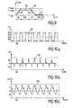
- the curve 40 of FIG. 4 represents the evolution of the instantaneous frequency of the output signal conventionally generated during a period. In portion 41, the instantaneous frequency increases from 2000Hz to 3500Hz. Then in the portion 42, the instantaneous frequency remains constant at 3500Hz.
- the frequency decreases from 3500Hz to 2000Hz and finally in the portion 44 it remains constant at 2000Hz.
- Each portion has a duration of 125 ms, the period being 500 ms.
- the curve 70 of FIG. 7 represents the envelope of the measurement curve of the corresponding acoustic pressure.
- portion 72 which corresponds to portion 42, the sound pressure reached is of the order of 6 Pa.
- the directive requires the average sound power to be between 105dB (A) and 118dB (A).
- the minimum level of 105dB (A) is difficult to reach, especially with the sirens comprising a piezoelectric crystal.
- US 6,339,368 B1 discloses an acoustic system comprising a power source, an acoustic transducer and a phase locked loop for detecting a phase difference between two signals taken at both terminals of the transducer and generating an output signal based on this difference in phase.
- a feedback link connecting the phase locked loop to a transducer terminal controls the transducer at a resonant frequency making the detected phase difference negligible.
- this system can excite the transducer at a substantially constant frequency.
- This system applies to a back-up alarm for a construction machine such as a bulldozer.
- the acoustic signal emitted is not modulated in frequency and is not identified as that of a vehicle burglar alarm siren.
- the present invention aims to increase the sound power of a siren whose sound signal is identifiable by the public warned as that of a veh ica alarm alarm.
- the invention provides a method of controlling a siren comprising a sound production device comprising a transducer able to emit a sound signal in response to an electrical control signal, said method comprising generating a an electrical control signal whose instantaneous frequency remains in a predefined frequency range, said control signal comprising at least a rising frequency signal portion whose instantaneous frequency is increasing and at least a downconverting signal portion whose instantaneous frequency is decreasing characterized in that said control signal comprises at least one constant-frequency signal portion whose instantaneous frequency is equal to a resonant frequency of said sound-producing device or to a sub-multiple of said resonance frequency
- the resonance frequency of the sound producing device makes it possible to increase the sound power of the siren.
- the inventors have surprisingly found that the acoustic signal emitted according to this method remains identifiable by the users as being that of a vehicle alarm siren, without significant differences in perception compared with conventional sirens, while it could be expected that transmitting at the resonance frequency and not at the frequencies usually used would result in a change in the perceived sound.
- said sound producing device comprises at least one radiating element coupled to said transducer, said resonant frequency corresponding to the resonance frequency of said sound production device as a whole.
- control signal is periodic, each period of the control signal comprising at least one up-frequency portion, at least one down-frequency portion and at least one constant-frequency portion.
- the duration of said at least one constant frequency portion is between 30% and 80% of said period, preferably between 50% and 70% of said period.
- This ratio makes it possible to increase the sound power while producing a sound remaining identifiable with that of a classic siren.
- the period comprises a single frequency portion and a single frequency portion.
- the period is between 0.33s and 1s, the durations of said rising and falling frequency portions being equal, a minimum frequency of said control signal being between 1800Hz and 2000Hz, a maximum frequency of said control signal being between 3500Hz and 3550Hz.
- said at least one up-frequency portion is such that the instantaneous frequency changes from a minimum frequency of said control signal to a maximum frequency of said control signal, said at least one down-frequency portion being such that the instantaneous frequency goes from the maximum frequency to the minimum frequency.
- the predefined frequency range is the range of 1800Hz to 3550Hz.
- the acoustic signal having an average power of between 105 dB (A) and 118 dB (A).
- the resonance frequency is obtained by exciting said transducer with a determined amplitude at a plurality of frequencies in said frequency range and retaining a frequency of said plurality of frequencies for which the acoustic power radiated by said Sound production device reaches a maximum level.
- the invention also provides a siren comprising a sound producing device comprising a transducer able to emit a sound signal in response to an electrical control signal, said siren comprising a control signal generator able to generate an electric control signal whose instantaneous frequency remains in a predefined frequency range, said control signal comprising at least a rising frequency signal portion whose instantaneous frequency increases and at least a down-frequency signal portion whose instantaneous frequency decreases, characterized in that said control signal generator is adapted to generate said control signal so that said control signal has at least a constant frequency signal portion whose instantaneous frequency is equal to a resonant frequency of said device for generating his or a submultiple of ladi the resonance frequency.
- the transducer is a piezoelectric crystal.
- control signal generator comprises a programmed microcontroller.
- the microcontroller comprises a memory storing control parameters, said control parameters comprising a minimum frequency, a maximum frequency, a stationary frequency, a passage time and a hold time.
- control signal generator is powered by the battery of a vehicle.
- the siren comprises an integrated battery for supplying the control signal generator independently.
- a siren 1 comprises a housing 2 comprising a lower part 3 and an upper part 4.
- a board 5 comprising an electronic circuit 20.
- the board 5 comprises a feed connector 6 allowing to supply the circuit 20 from the battery of a vehicle.
- the siren also includes a backup battery 7 for supplying the circuit 20 when the vehicle battery is disconnected or discharged. The power of the siren may be lower when it is running on the backup battery 7.
- An output connector 8 makes it possible to connect a piezoelectric transducer 9 to the card 5.
- a radiating membrane 10 is fixed on its periphery to a rim 11 formed at the bottom of a cylindrical recess 12 in the housing part 4 and the transducer 9 is fixed in the center of the membrane 10.
- the membrane 10 is made of stiff plastic, for example Milar.
- An acoustic horn 13 is fixed to the casing 4 in front of the membrane 10. It is dimensioned to broadcast the transmitted frequencies as well as possible. It also serves to protect the membrane from destructive attempts.
- FIG. 2 diagrammatically represents the electronic circuit 20 of the card 5.
- a microcontroller 21 comprises, among others, a memory 22 and an output terminal 24 for transmitting an output signal.
- the memory 22 permanently stores a control program and the fixed parameters of the control algorithm. These parameters are entered in the memory 22 during the manufacture of the Mermaid.
- Terminal 24 is connected to an amplification and shaping circuit 23.
- the circuit 23 comprises a shaping stage 25 comprising threshold inverters 27.
- the circuit 23 also comprises an amplification stage 26.
- the output of the circuit 23 is applied to the piezoelectric transducer 9 via the connector 8 .
- the microcontroller 21 When the microcontroller 21 detects an input signal indicating that it must emit a sound, it executes a program that generates a control signal on the terminal 24.
- This control signal is a low voltage square wave (0 / 3V) whose instantaneous frequency varies as explained below.
- the stage 25 makes it possible to modify, by acting on the threshold of the threshold inverters 27, the duty cycle of the control signal, to best correspond to the characteristics of the components of the stage 26. In the preferred embodiment, the ratio cyclic is 50%.
- the signal In stage 26, the signal is first amplified into an amplitude signal corresponding to the battery voltage of the vehicle, approximately 12V.
- the transistors 28 operate as switches supplying a step-up transformer 29 with a gain of about 3.
- FIG. 10a shows a square wave control signal 101 for an instantaneous frequency of 2500 Hz, amplitude 0 / 3V and duty cycle 50%.
- Figure 10b shows the corresponding pulse series 102. There is shown here the current across the transducer 9.
- Figure 10c shows the resulting sound pressure 103 measured near the siren under the conditions set by Directive 95/56 EC. The average power of this sound signal is about 105dB.
- the transducer 9 as well as the elements to which it is mechanically connected so as to produce a significant vibration as the membrane 10, the flange 11, the horn 13 and the part 4, form a sound producing device, which emits a sound signal in response to the signal applied to the transducer 9.
- the sound power of the sound signal varies with the frequency of the signal applied to the transducer 9.
- Figure 3 illustrates this dependence in an exemplary embodiment.
- Curve 30 gives the frequency response of the sound producing device, and has one or more local maxima 32.
- the resonance frequency of the sound producing device is called a frequency corresponding to the maximum or to a maximum. maxima of the response curve. Due to the attachment of the transducer 9 to the membrane 10, the resonant frequency of the sound producing device as a whole does not necessarily correspond exactly to the resonance frequency of the transducer 9 taken alone, which is generally specified by the manufacturer of the piezoelectric crystal.
- the resonance frequency can be measured on a single siren and stored in all the sirens of a series of production, which implies a reduced cost. For greater accuracy, it can also be measured and memorized individually for each siren in the series.
- the microcontroller In the siren of FIG. 1, the microcontroller generates a periodic control signal whose variation of the instantaneous frequency during a period 56 is represented by the curve 50 of FIG. 5.
- the portion 51 of duration equal to the time passage t rise, the instantaneous frequency increases from a minimum frequency f min of 2000Hz to a maximum frequency f max of 3500Hz.
- the portion 51 of duration equal to the hold time t high , the instantaneous frequency remains constant, equal to the stationary frequency f stat which is the resonance frequency of the sound production device.
- the portion 53 of duration equal to the crossing time, the frequency decreases from f max to f min and finally in the portion 54 of duration equal to the time of maintaining t low it is again constant and equal f stat .
- the rise time t and t fall is 100 ms.
- the times t high and t low are 150 ms.
- the period is 500 ms.
- the audible signal corresponding to this output signal complies with the requirements of Directive 95/56 EC. Due to the portions 52 and 54 at the resonance frequency, the average sound power of the siren 1 is greater than with the control signal of FIG. 4. One can for example obtain a power increase of 4 dB if a siren is controlled as shown in Figure 5 with respect to the same siren controlled as shown in Figure 4.
- the inventors have found that the sound signal of this siren was perceived by the man in a manner almost identical to that of the known siren, despite the fact that there is no longer a constant frequency portion equal to the maximum frequency nor at the minimum frequency. It is as if, during portions 52 and 54, the ear "held" the maximum frequencies f max or minimum f min reached.
- the proportion of 60% between the total duration of the portions at the frequency f stat and the period 56 is particularly advantageous for obtaining a siren whose sound signal is perceived almost identically to that of a conventional siren. Measurements of subjective parameters such as "Zwicker loudness" and "sharpness" have quantitatively confirmed this perception.
- FIG. 6 represents the steps of the control program executed by the microcontroller 21 to generate the control signal corresponding to FIG. 5.
- the portions 51 and 53 are represented as a linear variation of the instantaneous frequency, it may be possible to actually act of a step variation, regular or not, whose steps correspond to a sequence of respectively increasing or decreasing frequencies generated by the microcontroller and a sequence of corresponding calculated durations.
- the microcontroller receives an input signal indicating that the sound signal must be emitted. Such a signal can be produced by various detectors for recognizing abnormal situations.
- the execution of the program begins.
- the parameters stored in the memory 22 are read and transferred to the calculation memory. These are the durations of the steps 51 to 54 t rise respectively, t high, t t fall low, minimum frequency f min and f max maximum between which the instantaneous frequency varies during the steps 51 and 53, and frequency resonance of the device for producing its stat .
- the durations of the steps are calculated according to the durations of the portions 51 and 53, and the number of frequencies that the microcontroller is able to generate between the minimum and maximum frequencies. This number is for example 256, corresponding to a one-byte frequency coding between f min and f max .
- the microcontroller begins to generate a square wave whose instantaneous frequency varies over time according to Figure 5 and the values of the parameters.
- step 64 it tests whether the sound signal is issued for a time greater than or equal to the maximum allowed time, which is 25 to 30 s according to the directive. It is also tested whether the microcontroller has received an input signal indicating that the user of the vehicle has requested the stop of the sound signal. If at least one of these conditions is verified, proceed to step 65 corresponding to the stop of the sound signal and the end of the program. Otherwise we go to step 66 where it tests whether an elapsed time is greater than or equal to the duration calculated in step 63 for the current step. If this condition is not satisfied, it returns to step 64. If it is checked, go to step 67 where the elapsed time is reset and the instantaneous frequency is changed to that of the next step.
- Figure 9 is a representation similar to Figure 5, corresponding to another embodiment of the invention.
- Curve 90 includes portions 91, 92, 93 and 94 corresponding to portions 51, 52, 53 and 54, respectively.
- the instantaneous frequency is constant and equal to the resonance frequency, which in the example represented is equal to 3425 Hz.
- the instantaneous frequency is constant and equal to the minimum frequency f min .
- the same siren as that used for the measurements of FIG. 7 was controlled as illustrated in FIG. 9.
- the curve 80 of the figure represents the envelope of the measurements of the corresponding acoustic pressure.
- the acoustic pressure reached is of the order of 12 Pa, compared with 6 Pa of portion 72. The average acoustic power over a period is therefore increased substantially.
- a siren and a method for controlling a siren according to the invention may have at least some of the differences below.
- a period of the output signal may contain more than a rising frequency portion and more than a falling frequency portion. These portions may be in regular or irregular staircase. They may also not be stepped but have a continuous variation of the instantaneous frequency, if the control signal generator is capable of generating such a signal. By giving a particular shape to the frequency variation of the control signal, it is possible to make a siren whose sound is differentiable from that of sirens of other manufacturers. The increase in power resulting from the portions at the resonance frequency allows great freedom in the realization of the other portions.
- the output signal is not necessarily periodic. For example it can present a diagram of variation of the instantaneous frequency being repeated with small differences.
- the frequency is not necessarily equal to the resonant frequency. It can be a submultiple, the sound producing device then being resonantly excited by a harmonic of the control signal.
- the different constant frequency portions may correspond to different resonance frequencies.
- control signal generator comprises a generic microcontroller programmed by means of a specific program.
- the control signal is generated in digital form.
- control signal generator could be an assembly of specific electronic components.
- the control signal can be generated in analog form.
- any other transducer such that, once in place in the sound producing device, the latter has a resonance frequency.
Abstract
Description
La présente invention se rapporte à une sirène et à un procédé de commande d'une sirène. Plus particulièrement, la présente invention se rapporte aux sirènes d'alarme pour véhicule.The present invention relates to a siren and a method of controlling a siren. More particularly, the present invention relates to vehicle alarm sirens.
Il est connu d'utiliser une sirène d'alarme antivol pour prévenir les personnes à proximité d'une automobile parquée qu'une situation anormale est détectée, telle qu'un choc important, un bris de vitre ou une tentative de crochetage d'une portière.It is known to use an anti-theft alarm siren to warn people in the vicinity of a parked car that an abnormal situation is detected, such as a major shock, breakage of glass, or an attempt to pick a lock. door.
La puissance sonore de la sirène doit être à la fois suffisamment élevée pour pouvoir être entendue depuis une distance relativement grande, et suffisamment faible pour ne pas nuire à la sécurité et au bien-être des personnes se trouvant à proximité, c'est-à-dire respecter des contraintes de santé publique et d'ordre public. Le signal sonore émis par la sirène doit être identifiable, c'est-à-dire qu'il faut pouvoir le distinguer des autres sons pouvant être émis dans l'environnement de l'automobile, par exemple le son d'un klaxon ou le signal d'avertissement d'un camion roulant en marche arrière.The sound power of the siren must be both high enough to be heard from a relatively large distance, and low enough not to affect the safety and well-being of nearby people, that is, to say to respect constraints of public health and public order. The sound signal emitted by the siren must be identifiable, that is to say, it must be able to distinguish it from other sounds that may be emitted in the automobile environment, for example the sound of a horn or the sound Warning signal of a truck traveling in reverse.
La directive européenne 95/56 CE normalise les systèmes d'alarmes pour véhicule en imposant des contraintes sur la puissance sonore et sur les différents types de signaux pouvant être émis, parmi lesquels on trouve les signaux du type modulé en fréquence. Pour de tels signaux, la directive exige un son continu et uniforme, sauf pour le passage égale d'une gamme de fréquence importante dans la gamme 1800Hz à 3550Hz dans les deux sens, avec une fréquence de passage de 1 à 3 Hz. Classiquement de tels signaux présentent donc une période de 0.33 à 1 seconde comportant une première portion dans laquelle la fréquence instantanée croît de manière à passer de 2000Hz à 3500Hz, une deuxième portion à 3500Hz, une troisième portion dans laquelle la fréquence instantanée décroît de manière à passer de 3500Hz à 2000Hz et une quatrième portion à 2000Hz. Ce type de signal est identifié par les utilisateurs comme provenant d'une sirène d'alarme pour véhicule.The
Dans une sirène connue, un générateur de signal produit un signal de sortie qui, une fois amplifié, transformé et appliqué à un cristal piézo-électrique, produit un signal sonore conforme aux exigences de la directive 95/56 CE, que les constructeurs d'automobiles et utilisateurs identifient comme étant celui d'une sirène d'alarme pour véhicule. Pour cela, le signal de sortie du générateur est une onde carrée dont la fréquence instantanée varie selon un schéma périodique. La courbe 40 de la figure 4 représente l'évolution de la fréquence instantanée du signal de sortie classiquement généré, au cours d'une période. Dans la portion 41, la fréquence instantanée croît de 2000Hz à 3500Hz. Ensuite dans la portion 42, la fréquence instantanée reste constante à 3500Hz. Dans la portion 43, la fréquence décroît de 3500Hz à 2000Hz et enfin dans la portion 44 elle reste constante à 2000Hz. Chacune des portions a une durée de 125 ms, la période étant de 500 ms. La courbe 70 de la figure 7 représente l'enveloppe de la courbe de mesures de la pression acoustique correspondante. Dans la portion 72 qui correspond à la portion 42, la pression acoustique atteinte est de l'ordre de 6 Pa.In a known siren, a signal generator produces an output signal which, when amplified, transformed and applied to a piezoelectric crystal, produces a sound signal in accordance with the requirements of
La directive exige que la puissance sonore moyenne soit comprise entre 105dB(A) et 118dB(A). Dans les sirènes actuelles, le niveau minimal de 105dB(A) est difficilement atteint, notamment avec les sirènes comprenant un cristal piézo-électrique.The directive requires the average sound power to be between 105dB (A) and 118dB (A). In the current sirens, the minimum level of 105dB (A) is difficult to reach, especially with the sirens comprising a piezoelectric crystal.
US 6,339,368 B1 décrit un système acoustique comprenant une source d'énergie, un transducteur acoustique et une boucle à verrouillage de phase pour détecter une différence de phase entre deux signaux pris aux deux bornes du transducteur et générer un signal de sortie fondé sur cette différence de phase. Une liaison de rétroaction reliant la boucle à verrouillage de phase à une borne du transducteur permet de piloter le transducteur à une fréquence de résonance rendant la différence de phase détectée négligeable. En fonctionnement, ce système ne peut exciter le transducteur qu'à une fréquence sensiblement constante. Ce système s'applique à une alarme de recul pour un engin de chantier tel qu'un bulldozer. Le signal sonore émis n'est pas modulé en fréquence et n'est pas identifié comme celui une sirène d'alarme antivol pour véhicule.US 6,339,368 B1 discloses an acoustic system comprising a power source, an acoustic transducer and a phase locked loop for detecting a phase difference between two signals taken at both terminals of the transducer and generating an output signal based on this difference in phase. A feedback link connecting the phase locked loop to a transducer terminal controls the transducer at a resonant frequency making the detected phase difference negligible. In operation, this system can excite the transducer at a substantially constant frequency. This system applies to a back-up alarm for a construction machine such as a bulldozer. The acoustic signal emitted is not modulated in frequency and is not identified as that of a vehicle burglar alarm siren.
La présente invention à pour but d'augmenter la puissance sonore d' une sirène dont le signal sonore est identifiable par le public averti comme celui d'une s irène d'alarme pour véh icule.The present invention aims to increase the sound power of a siren whose sound signal is identifiable by the public warned as that of a veh ica alarm alarm.
Pour cela, l'invention fournit un procédé de commande d'une sirène comprenant un dispositif de production de son comportant un transducteur apte à émettre un signal sonore en réaction à un signal de commande électrique, ledit procédé comprenant le fait de générer un signal de commande électrique dont la fréquence instantanée reste dans une gamme de fréquence prédéfinie, ledit signal de commande comprenant au moins une portion de signal à fréquence montante dont la fréquence instantanée croît et au moins une portion de signal à fréquence descendante dont la fréquence instantanée décroît, caractérisé en ce que ledit signal de commande comprend au moins une portion de signal à fréquence constante dont la fréquence instantanée est égale à une fréquence de résonance dudit dispositif de production de son ou à un sous-multiple de ladite fréquence de résonanceFor this, the invention provides a method of controlling a siren comprising a sound production device comprising a transducer able to emit a sound signal in response to an electrical control signal, said method comprising generating a an electrical control signal whose instantaneous frequency remains in a predefined frequency range, said control signal comprising at least a rising frequency signal portion whose instantaneous frequency is increasing and at least a downconverting signal portion whose instantaneous frequency is decreasing characterized in that said control signal comprises at least one constant-frequency signal portion whose instantaneous frequency is equal to a resonant frequency of said sound-producing device or to a sub-multiple of said resonance frequency
Le fait d'utiliser la fréquence de résonance du dispositif de production de son permet d'augmenter la puissance sonore de la sirène. De plus, les inventeurs ont constaté de manière surprenante que le signal sonore émis selon ce procédé restait identifiable par les utilisateurs comme étant celui d'une sirène d'alarme pour véhicule, sans différences significatives de perception par rapport aux sirènes classiques, alors qu'on pouvait s'attendre à ce que le fait d'émettre à la fréquence de résonance et non aux fréquences habituellement utilisées entraînerait un changement dans le son perçu.Using the resonance frequency of the sound producing device makes it possible to increase the sound power of the siren. In addition, the inventors have surprisingly found that the acoustic signal emitted according to this method remains identifiable by the users as being that of a vehicle alarm siren, without significant differences in perception compared with conventional sirens, while it could be expected that transmitting at the resonance frequency and not at the frequencies usually used would result in a change in the perceived sound.
De préférence, ledit dispositif de production de son comporte au moins un organe rayonnant couplé audit transducteur, ladite fréquence de résonance correspondant à la fréquence de résonance dudit dispositif de production de son dans son ensemble.Preferably, said sound producing device comprises at least one radiating element coupled to said transducer, said resonant frequency corresponding to the resonance frequency of said sound production device as a whole.
Le fait d'utiliser la fréquence de résonance du dispositif et non celle du transducteur considéré isolément permet de tirer profit au mieux des caractéristiques matérielles de la sirène.The fact of using the resonance frequency of the device and not that of the transducer considered in isolation makes it possible to make the most of the material characteristics of the siren.
Dans un mode de réalisation préféré, le signal de commande est périodique, chaque période du signal de commande comprenant au moins une portion à fréquence montante, au moins une portion à fréquence descendante et au moins une portion à fréquence constante.In a preferred embodiment, the control signal is periodic, each period of the control signal comprising at least one up-frequency portion, at least one down-frequency portion and at least one constant-frequency portion.
Avantageusement, la durée de ladite au moins une portion à fréquence constante est comprise entre 30% et 80% de ladite période, de préférence entre 50% et 70% de ladite période.Advantageously, the duration of said at least one constant frequency portion is between 30% and 80% of said period, preferably between 50% and 70% of said period.
Ce rapport permet d'augmenter la puissance sonore tout en produisant un son restant identifiable à de celui d'une sirène classique.This ratio makes it possible to increase the sound power while producing a sound remaining identifiable with that of a classic siren.
Avantageusement, la période comprend une seule portion à fréquence montante et une seule portion à fréquence descendante.Advantageously, the period comprises a single frequency portion and a single frequency portion.
De préférence, la période est comprise entre 0,33s et 1s, les durées desdites portions à fréquence montante et descendante étant égales, une fréquence minimale dudit signal de commande étant comprise entre 1800Hz et 2000Hz, une fréquence maximale dudit signal de commande étant comprise entre 3500Hz et 3550Hz.Preferably, the period is between 0.33s and 1s, the durations of said rising and falling frequency portions being equal, a minimum frequency of said control signal being between 1800Hz and 2000Hz, a maximum frequency of said control signal being between 3500Hz and 3550Hz.
De préférence, ladite au moins une portion à fréquence montante est telle que la fréquence instantanée passe d'une fréquence minimale dudit signal de commande à une fréquence maximale dudit signal de commande, ladite au moins une portion à fréquence descendante étant telle que la fréquence instantanée passe de la fréquence maximale à la fréquence minimale.Preferably, said at least one up-frequency portion is such that the instantaneous frequency changes from a minimum frequency of said control signal to a maximum frequency of said control signal, said at least one down-frequency portion being such that the instantaneous frequency goes from the maximum frequency to the minimum frequency.
Selon un mode de réalisation préféré, la gamme de fréquence prédéfinie est la gamme de 1800Hz à 3550Hz.According to a preferred embodiment, the predefined frequency range is the range of 1800Hz to 3550Hz.
Avantageusement, le signal sonore présentant une puissance moyenne comprise entre 105dB(A) et118dB(A).Advantageously, the acoustic signal having an average power of between 105 dB (A) and 118 dB (A).
Dans un mode de réalisation particulier, la fréquence de résonance est obtenue en excitant ledit transducteur avec une amplitude déterminée à une pluralité de fréquences situées dans ladite gamme de fréquence et en retenant une fréquence de ladite pluralité de fréquences pour laquelle la puissance acoustique rayonnée par ledit dispositif de production de son atteint un niveau maximum.In a particular embodiment, the resonance frequency is obtained by exciting said transducer with a determined amplitude at a plurality of frequencies in said frequency range and retaining a frequency of said plurality of frequencies for which the acoustic power radiated by said Sound production device reaches a maximum level.
L'invention fournit également une sirène comprenant un dispositif de production de son comportant un transducteur apte à émettre un signal sonore en réaction à un signal de commande électrique, ladite sirène comprenant un générateur de signal de commande apte à générer un de signal de commande électrique dont la fréquence instantanée reste dans une gamme de fréquence prédéfinie, ledit signal de commande comprenant au moins une portion de signal à fréquence montante dont la fréquence instantanée croît et au moins une portion de signal à fréquence descendante dont la fréquence instantanée décroît, caractérisé en ce que ledit générateur de signal de commande est apte à générer ledit signal de commande de manière à ce que ledit signal de commande présente au moins une portion de signal à fréquence constante dont la fréquence instantanée est égale à une fréquence de résonance dudit dispositif de production de son ou à un sous-multiple de ladite fréquence de résonance.The invention also provides a siren comprising a sound producing device comprising a transducer able to emit a sound signal in response to an electrical control signal, said siren comprising a control signal generator able to generate an electric control signal whose instantaneous frequency remains in a predefined frequency range, said control signal comprising at least a rising frequency signal portion whose instantaneous frequency increases and at least a down-frequency signal portion whose instantaneous frequency decreases, characterized in that said control signal generator is adapted to generate said control signal so that said control signal has at least a constant frequency signal portion whose instantaneous frequency is equal to a resonant frequency of said device for generating his or a submultiple of ladi the resonance frequency.
De préférence, le transducteur est un cristal piézo-électrique.Preferably, the transducer is a piezoelectric crystal.
Avantageusement, le générateur de signal de commande comporte un microcontrôleur programmé.Advantageously, the control signal generator comprises a programmed microcontroller.
Selon un mode de réalisation particulier, le microcontrôleur comporte une mémoire mémorisant des paramètres de commande, lesdits paramètres de commande comprenant une fréquence minimale, une fréquence maximale, une fréquence stationnaire, un temps de passage et un temps de maintient.According to a particular embodiment, the microcontroller comprises a memory storing control parameters, said control parameters comprising a minimum frequency, a maximum frequency, a stationary frequency, a passage time and a hold time.
Ainsi, on peut facilement adapter la sirène en modifiant le programme ou les paramètres.Thus, one can easily adapt the siren by modifying the program or the parameters.
De préférence, le générateur de signal de commande est alimenté par la batterie d'un véhicule.Preferably, the control signal generator is powered by the battery of a vehicle.
Avantageusement, la sirène comprend une batterie intégrée pour alimenter le générateur de signal de commande de manière indépendante.Advantageously, the siren comprises an integrated battery for supplying the control signal generator independently.
L'invention sera mieux comprise, et d'autres buts, détails, caractéristiques et avantages de celle-ci apparaîtront plus clairement au cours de la description suivante de plusieurs modes de réalisation particuliers de l'invention, donnés uniquement à titre illustratif et non limitatif, en référence aux dessins annexés. Sur ces dessins :
- La figure 1 représente une section d'une sirène selon un mode de réalisation de l'invention ;
- la figure 2 est un schéma du circuit utilisé dans la sirène de la figure 1 ;
- la figure 3 est un graphe représentant la puissance acoustique de la sirène de la figure 1 en fonction de la fréquence du signal de commande ;
- la figure 4 est un graphe représentant l'évolution de la fréquence instantanée d'un signal de commande selon l'art antérieur ;
- la figure 5 est un graphe représentant l'évolution de la fréquence instantanée d'un signal de commande selon un mode de réalisation de l'invention ;
- la figure 6 représente les étapes d'un programme mettant en oeuvre le procédé selon le mode de réalisation de la figure 5;
- la figure 7 représente la pression acoustique d'une sirène commandée comme illustré figure 4 ;
- la figure 8 représente la pression acoustique d'une sirène commandée comme illustré figure 9 ;
- la figure 9 est une représentation similaire à la figure 5, selon un autre mode de réalisation de l'invention ;
- la figure 10a représente un signal de commande carré mis en forme par l'étage 25 de la figure 2 ;
- la figure 10b représente un signal de courant correspondant aux bornes du transducteur, et
- la figure 10c représente le signal de pression acoustique correspondant mesuré à proximité de la sirène.
- Figure 1 shows a section of a siren according to one embodiment of the invention;
- Figure 2 is a circuit diagram used in the siren of Figure 1;
- FIG. 3 is a graph showing the acoustic power of the siren of FIG. 1 as a function of the frequency of the control signal;
- FIG. 4 is a graph showing the evolution of the instantaneous frequency of a control signal according to the prior art;
- FIG. 5 is a graph showing the evolution of the instantaneous frequency of a control signal according to one embodiment of the invention;
- FIG. 6 represents the steps of a program implementing the method according to the embodiment of FIG. 5;
- Figure 7 shows the sound pressure of a siren controlled as shown in Figure 4;
- Figure 8 shows the sound pressure of a siren controlled as shown in Figure 9;
- Figure 9 is a representation similar to Figure 5, according to another embodiment of the invention;
- Fig. 10a shows a square control signal shaped by
stage 25 of Fig. 2; - FIG. 10b represents a current signal corresponding to the terminals of the transducer, and
- Figure 10c shows the corresponding sound pressure signal measured near the siren.
En référence à la figure 1, une sirène 1 comprend un boîtier 2 comprenant une partie inférieure 3 et une partie supérieure 4. Dans la partie 3 se trouve une carte 5 comprenant un circuit électronique 20. La carte 5 comporte un connecteur d'alimentation 6 permettant d'alimenter le circuit 20 depuis la batterie d'un véhicule. La sirène comporte également une batterie de secours 7 permettant d'alimenter le circuit 20 quand la batterie du véhicule est déconnectée ou déchargée. La puissance de la sirène peut être plus faible quand elle fonctionne sur la batterie de secours 7.With reference to FIG. 1, a
Un connecteur de sortie 8 permet de connecter un transducteur piézo-électrique 9 à la carte 5. Une membrane rayonnante 10 est fixée sur sa périphérie à un rebord 11 formé au fond d'un renfoncement cylindrique 12 dans la partie de boîtier 4 et le transducteur 9 est fixé au centre de la membrane 10. La membrane 10 est en plastique raide, par exemple en Milar. Un cornet acoustique 13 est fixé au boîtier 4 devant la membrane 10. Il est dimensionné pour diffuser au mieux les fréquences émises. Il a aussi pour fonction de protéger la membrane des tentatives de destructions.An
La figure 2 représente schématiquement le circuit électronique 20 de la carte 5. Un microcontrôleur 21 comprend, entre autres, une mémoire 22 et une borne de sortie 24 pour émettre un signal de sortie. La mémoire 22 stocke de manière permanente un programme de commande et les paramètres fixes de l'algorithme de commande. Ces paramètres sont entrés dans la mémoire 22 lors de la fabrication de la sirène. La borne 24 est reliée à un circuit d'amplification et de mise en forme 23.FIG. 2 diagrammatically represents the
Le circuit 23 comprend un étage de mise en forme 25 comprenant des inverseurs à seuils 27. Le circuit 23 comprend également un étage d'amplification 26. La sortie du circuit 23 est appliquée au transducteur piézo-électrique 9 par l'intermédiaire du connecteur 8.The
Quand le microcontrôleur 21 détecte un signal d'entrée lui indiquant qu'il doit émettre un son, il exécute un programme qui génère un signal de commande sur la borne 24. Ce signal de commande est une onde carrée basse tension (0/3V) dont la fréquence instantanée varie comme expliqué ci-dessous. L'étage 25 permet de modifier, en jouant sur le seuil des inverseurs à seuils 27, le rapport cyclique du signal de commande, pour correspondre au mieux aux caractéristiques des composants de l'étage 26. Dans le mode de réalisation préféré, le rapport cyclique est de 50%. Dans l'étage 26, le signal est d'abord amplifié en un signal d'amplitude correspondant à la tension de la batterie du véhicule, d'environ 12V. Les transistors 28 fonctionnent en interrupteurs alimentant un transformateur élévateur de tension 29 d'un gain d'environ 3. Certains composants de l'étage 26 étant non linéaires, des fronts importants sont créés de sorte que le signal n'est plus une onde carrée mais une série d'impulsions dont l'amplitude est environ 50V. Cette série d'impulsions est appliquée au transducteur 9 qui entre donc en vibration, entraînant avec lui la membrane 10. Un son est donc produit, dont la fréquence fondamentale correspond à la fréquence instantanée du signal de commande.When the
La figure 10a représente un signal de commande 101 en onde carrée pour une fréquence instantanée de 2500 Hz, d'amplitude 0/3V et de rapport cyclique 50%. La figure 10b représente la série d'impulsions 102 correspondante. On a représenté ici le courant aux bornes du transducteur 9. La figure 10c représente la pression acoustique 103 résultante mesurée à proximité de la sirène dans les conditions fixées par la directive 95/56 CE. La puissance moyenne de ce signal sonore est de 105dB environ.FIG. 10a shows a square
Le transducteur 9 ainsi que les éléments auxquels il est mécaniquement lié de manière à y produire une vibration significative comme la membrane 10, le rebord 11, le cornet 13 et la partie 4, forment un dispositif de production de son, qui émet un signal sonore en réponse au signal appliqué au transducteur 9. Pour une amplitude constante, la puissance sonore du signal sonore varie avec la fréquence du signal appliqué au transducteur 9. La figure 3 illustre cette dépendance dans un exemple de réalisation. La courbe 30 donne la réponse en fréquence du dispositif de production de son, et présente un ou plusieurs maxima locaux 32. Dans le cadre de cette description, on appelle fréquence de résonance du dispositif de production de son une fréquence correspondant au maximum ou à un des maxima de la courbe de réponse. Du fait de la fixation du transducteur 9 à la membrane 10, la fréquence de résonance du dispositif de production de son dans son ensemble ne correspond pas nécessairement exactement à la fréquence de résonance du transducteur 9 pris isolément, qui est généralement spécifié par le fabricant du cristal piézoélectrique.The transducer 9 as well as the elements to which it is mechanically connected so as to produce a significant vibration as the
La fréquence de résonance peut être mesurée sur une seule sirène et mémorisée dans toutes les sirènes d'une série de production, ce qui implique un coût réduit. Pour une plus grande précision, elle peut aussi être mesurée et mémorisée individuellement pour chaque sirène de la série.The resonance frequency can be measured on a single siren and stored in all the sirens of a series of production, which implies a reduced cost. For greater accuracy, it can also be measured and memorized individually for each siren in the series.
Dans la sirène de la figure 1, le microcontrôleur génère un signal de commande périodique dont la variation de la fréquence instantanée au cours d'une période 56 est représentée par la courbe 50 de la figure 5. Dans la portion 51 de durée égale au temps de passage trise, la fréquence instantanée croît d'une fréquence minimale fmin de 2000Hz à une fréquence maximale fmax de 3500Hz. Ensuite dans la portion 51 de durée égale au temps de maintient thigh, la fréquence instantanée reste constante, égale à la fréquence stationnaire fstat qui est la fréquence de résonance du dispositif de production de son. Dans la portion 53 de durée égale au temps de passage trait, la fréquence décroît de fmax à fmin et enfin dans la portion 54 de durée égale au temps de maintient tlow elle est de nouveau constante et égale fstat. Les temps trise et tfall sont de 100 ms. Les temps thigh et tlow sont de 150 ms. La période est de 500 ms.In the siren of FIG. 1, the microcontroller generates a periodic control signal whose variation of the instantaneous frequency during a
Le signal sonore correspondant à ce signal de sortie est conforme aux exigences de la directive 95/56 CE. Du fait des portions 52 et 54 à la fréquence de résonance, la puissance sonore moyenne de la sirène 1 est plus importante qu'avec le signal de commande de la figure 4. On peut par exemple obtenir une augmentation de puissance de 4dB si une sirène est commandée comme indiqué figure 5 par rapport à la même sirène commandée comme indiqué figure 4.The audible signal corresponding to this output signal complies with the requirements of
Les inventeurs ont constaté que le signal sonore de cette sirène était perçu par l'homme de manière quasi-identique à celui de la sirène connue, malgré le fait qu'il n'y a plus de portion à fréquence constante égale à la fréquence maximale ni à la fréquence minimale. Tout se passe comme si, lors des portions 52 et 54, l'oreille « retenait » les fréquences maximale fmax ou minimale fmin atteintes. Par exemple, la proportion de 60% entre la durée totale des portions à la fréquence fstat et la période 56 est particulièrement avantageuse pour obtenir une sirène dont le signal sonore est perçu de manière quasi-identique à celui d'une sirène classique. Des mesures de paramètres subjectifs tels que la « loudness de Zwicker » et la « sharpness » ont permis de confirmer quantitativement cette perception.The inventors have found that the sound signal of this siren was perceived by the man in a manner almost identical to that of the known siren, despite the fact that there is no longer a constant frequency portion equal to the maximum frequency nor at the minimum frequency. It is as if, during
La figure 6 représente les étapes du programme de commande exécuté par le microcontrôleur 21 pour générer le signal de commande correspondant à la figure 5. Signalons que bien que les portions 51 et 53 soient représentées comme une variation linéaire de la fréquence instantanée, il peut s'agir en réalité d'une variation en escalier, régulière ou non, dont les marches correspondent à une suite de fréquences respectivement croissantes ou décroissantes générées par le microcontrôleur et à une suite de durées correspondantes calculées.FIG. 6 represents the steps of the control program executed by the
En 61, le microcontrôleur reçoit un signal d'entrée indiquant que le signal sonore doit être émis. Un tel signal peut être produit par divers détecteurs destinés à reconnaître des situations anormales. L'exécution du programme commence. En 62, les paramètres stockés dans la mémoire 22 sont lus et transféré dans la mémoire de calcul. Il s'agit des durées des étapes 51 à 54 respectivement trise, thigh, tfall tlow, des fréquences minimale fmin et maximale fmax entre lesquelles la fréquence instantanée varie au cours des étapes 51 et 53, et de la fréquence de résonance du dispositif de production de son fstat.At 61, the microcontroller receives an input signal indicating that the sound signal must be emitted. Such a signal can be produced by various detectors for recognizing abnormal situations. The execution of the program begins. At 62, the parameters stored in the
En 63, les durées des marches sont calculées en fonction des durées des portions 51 et 53, et du nombre de fréquences que le microcontrôleur est capable de générer entre les fréquences minimale et maximale. Ce nombre est par exemple de 256, correspondant à un codage des fréquences sur un octet entre fmin et fmax. Le microcontrôleur commence à générer une onde carrée dont la fréquence instantanée varie au cours du temps conformément à la figure 5 et aux valeurs des paramètres.In 63, the durations of the steps are calculated according to the durations of the
En 64, on teste si le signal sonore est émis depuis un temps supérieur ou égale au temps maximal autorisé, qui est de 25 à 30 s selon la directive. On teste également si le microcontrôleur a reçu un signal d'entrée lui indiquant que l'utilisateur du véhicule a demandé l'arrêt du signal sonore. Si l'une au moins de ces conditions est vérifiée, on passe à l'étape 65 correspondant à l'arrêt du signal sonore et à la fin du programme. Sinon on passe à l'étape 66 où on teste si une durée écoulée est supérieure ou égale à la durée calculée à l'étape 63 pour la marche en cours. Si cette condition n'est pas vérifiée, on retourne à l'étape 64. Si elle est vérifiée, on passe à l'étape 67 où la durée écoulée est remise à zéro et la fréquence instantanée est changée en celle de la marche suivante.In 64, it tests whether the sound signal is issued for a time greater than or equal to the maximum allowed time, which is 25 to 30 s according to the directive. It is also tested whether the microcontroller has received an input signal indicating that the user of the vehicle has requested the stop of the sound signal. If at least one of these conditions is verified, proceed to step 65 corresponding to the stop of the sound signal and the end of the program. Otherwise we go to step 66 where it tests whether an elapsed time is greater than or equal to the duration calculated in step 63 for the current step. If this condition is not satisfied, it returns to step 64. If it is checked, go to step 67 where the elapsed time is reset and the instantaneous frequency is changed to that of the next step.
En 68 on teste si la fréquence instantanée a atteint la fréquence minimale fmin ou maximale fmax. Si c'est le cas, on passe en 69 où la fréquence instantanée est changée en la fréquence de résonance fstat, et on attend la durée de la portion 52 ou 54 avant de retourner en 64. Sinon, on retourne directement en 64.At 68 it is tested whether the instantaneous frequency has reached the minimum frequency f min or maximum f max . If this is the case, we go to 69 where the instantaneous frequency is changed to the resonance frequency f stat , and we wait for the duration of the
La figure 9 est une représentation similaire à la figure 5, correspondant à une autre mode de réalisation de l'invention. La courbe 90 comprend les portions 91, 92, 93 et 94 correspondant aux portions 51, 52, 53 et 54 respectivement. Dans ce mode de réalisation, durant la portion 92, la fréquence instantanée est constante et égale à la fréquence de résonance, qui dans l'exemple représenté vaut 3425Hz. Durant la portion 94, la fréquence instantanée est constante et égale à la fréquence minimale fmin. La même sirène que celle utilisée pour les mesures de la figure 7 a été commandée comme illustré figure 9. La courbe 80 de la figure représente l'enveloppe des mesures de la pression acoustique correspondante. Dans la portion 82 correspondant à la portion 92, la pression acoustique atteinte est de l'ordre de 12 Pa, à comparer avec les 6 Pa de la portion 72. La puissance acoustique moyenne sur une période est donc augmentée sensiblement.Figure 9 is a representation similar to Figure 5, corresponding to another embodiment of the invention.
En variante aux modes de réalisation de l'invention qui viennent d'être décrits, une sirène et un procédé de commande d'une sirène selon l'invention peuvent présenter au moins certaines des différences ci-dessous.As an alternative to the embodiments of the invention which have just been described, a siren and a method for controlling a siren according to the invention may have at least some of the differences below.
Un période du signal de sortie peut contenir plus qu'une portion à fréquence montante et plus qu'une portion à fréquence descendante. Ces portions peuvent être en escalier régulier ou irrégulier. Elles peuvent aussi ne pas être en escalier mais présenter une variation continue de la fréquence instantanée, si le générateur de signal de commande est capable de générer un tel signal. En donnant une forme particulière à la variation de fréquence du signal de commande, il est possible de réaliser une sirène dont le son est différentiable de celui des sirènes d'autres constructeurs. L'augmentation de puissance résultant des portions à la fréquence de résonance permet une grande liberté dans la réalisation des autres portions.A period of the output signal may contain more than a rising frequency portion and more than a falling frequency portion. These portions may be in regular or irregular staircase. They may also not be stepped but have a continuous variation of the instantaneous frequency, if the control signal generator is capable of generating such a signal. By giving a particular shape to the frequency variation of the control signal, it is possible to make a siren whose sound is differentiable from that of sirens of other manufacturers. The increase in power resulting from the portions at the resonance frequency allows great freedom in the realization of the other portions.
Le signal de sortie n'est pas nécessairement périodique. Par exemple il peut présenter un schéma de variation de la fréquence instantanée se répétant avec des petites différences.The output signal is not necessarily periodic. For example it can present a diagram of variation of the instantaneous frequency being repeated with small differences.
Durant les portions à fréquence constante, la fréquence n'est pas nécessairement égale à la fréquence de résonance. Elle peut en être un sous-multiple, le dispositif de production de son étant alors excité de manière résonnante par une harmonique du signal de commande.During constant frequency portions, the frequency is not necessarily equal to the resonant frequency. It can be a submultiple, the sound producing device then being resonantly excited by a harmonic of the control signal.
Il n'y a pas nécessairement deux portions à la fréquence de résonance. Il peut y en avoir une seule ou plus de deux. Si le dispositif de production de son possède plusieurs fréquences de résonance, les différentes portions à fréquence constante peuvent correspondre à différentes fréquences de résonances.There are not necessarily two portions at the resonant frequency. There can be one or more than two. If the sound producing device has several resonant frequencies, the different constant frequency portions may correspond to different resonance frequencies.
Dans l'exemple décrit, le générateur de signal de commande comprend un microcontrôleur générique programmé au moyen d'un programme spécifique. Le signal de commande est généré sous forme numérique. D'autres possibilités peuvent être envisagées. Par exemple le générateur de signal de commande pourrait être un assemblage de composants électroniques spécifiques. Le signal de commande peut être généré sous forme analogique.In the example described, the control signal generator comprises a generic microcontroller programmed by means of a specific program. The control signal is generated in digital form. Other possibilities can be envisaged. For example, the control signal generator could be an assembly of specific electronic components. The control signal can be generated in analog form.
On peut utiliser, à la place du cristal piézo-électrique, tout autre transducteur tel que, une fois en place dans le dispositif de production de son, celui-ci présente une fréquence de résonance.Instead of the piezoelectric crystal, it is possible to use any other transducer such that, once in place in the sound producing device, the latter has a resonance frequency.
Bien que l'invention ait été décrite en liaison avec des modes de réalisation particuliers, il est bien évident qu'elle n'y est nullement limitée et qu'elle comprend tous les équivalents techniques des moyens décrits ainsi que leurs combinaisons si celles-ci entrent dans le cadre de l'invention.Although the invention has been described in connection with particular embodiments, it is obvious that it is not limited thereto and that it includes all the technical equivalents of the means described and their combinations if they are within the scope of the invention.
Claims (16)
Priority Applications (3)
| Application Number | Priority Date | Filing Date | Title |
|---|---|---|---|
| DE602004004403T DE602004004403T2 (en) | 2004-10-27 | 2004-10-27 | Warning siren for vehicle |
| AT04292551T ATE352083T1 (en) | 2004-10-27 | 2004-10-27 | WARNING SIREN FOR VEHICLE |
| EP04292551A EP1653420B1 (en) | 2004-10-27 | 2004-10-27 | Warning siren for vehicle |
Applications Claiming Priority (1)
| Application Number | Priority Date | Filing Date | Title |
|---|---|---|---|
| EP04292551A EP1653420B1 (en) | 2004-10-27 | 2004-10-27 | Warning siren for vehicle |
Publications (2)
| Publication Number | Publication Date |
|---|---|
| EP1653420A1 true EP1653420A1 (en) | 2006-05-03 |
| EP1653420B1 EP1653420B1 (en) | 2007-01-17 |
Family
ID=34931485
Family Applications (1)
| Application Number | Title | Priority Date | Filing Date |
|---|---|---|---|
| EP04292551A Active EP1653420B1 (en) | 2004-10-27 | 2004-10-27 | Warning siren for vehicle |
Country Status (3)
| Country | Link |
|---|---|
| EP (1) | EP1653420B1 (en) |
| AT (1) | ATE352083T1 (en) |
| DE (1) | DE602004004403T2 (en) |
Cited By (1)
| Publication number | Priority date | Publication date | Assignee | Title |
|---|---|---|---|---|
| EP2244235A1 (en) | 2009-04-21 | 2010-10-27 | Delphi Technologies, Inc. | Method for self-calibrating an alarm siren module for a vehicle |
Families Citing this family (1)
| Publication number | Priority date | Publication date | Assignee | Title |
|---|---|---|---|---|
| CN110017999A (en) * | 2019-04-12 | 2019-07-16 | 武汉格罗夫氢能汽车有限公司 | A method of test car door resonance |
Citations (2)
| Publication number | Priority date | Publication date | Assignee | Title |
|---|---|---|---|---|
| US5012221A (en) * | 1989-03-24 | 1991-04-30 | Siren Sounds, Inc. | Emergency vehicle audible warning system and method |
| WO1998011666A1 (en) * | 1996-09-11 | 1998-03-19 | Robert Bosch Gmbh | A sounder control system |
-
2004
- 2004-10-27 AT AT04292551T patent/ATE352083T1/en not_active IP Right Cessation
- 2004-10-27 DE DE602004004403T patent/DE602004004403T2/en active Active
- 2004-10-27 EP EP04292551A patent/EP1653420B1/en active Active
Patent Citations (2)
| Publication number | Priority date | Publication date | Assignee | Title |
|---|---|---|---|---|
| US5012221A (en) * | 1989-03-24 | 1991-04-30 | Siren Sounds, Inc. | Emergency vehicle audible warning system and method |
| WO1998011666A1 (en) * | 1996-09-11 | 1998-03-19 | Robert Bosch Gmbh | A sounder control system |
Cited By (1)
| Publication number | Priority date | Publication date | Assignee | Title |
|---|---|---|---|---|
| EP2244235A1 (en) | 2009-04-21 | 2010-10-27 | Delphi Technologies, Inc. | Method for self-calibrating an alarm siren module for a vehicle |
Also Published As
| Publication number | Publication date |
|---|---|
| DE602004004403D1 (en) | 2007-03-08 |
| DE602004004403T2 (en) | 2007-10-18 |
| EP1653420B1 (en) | 2007-01-17 |
| ATE352083T1 (en) | 2007-02-15 |
Similar Documents
| Publication | Publication Date | Title |
|---|---|---|
| EP3137871B1 (en) | System for evaluating the condition of a tyre | |
| EP1330372B1 (en) | Low-power consumption system for monitoring pressure in a tyre | |
| FR2828741A1 (en) | OBSTACLE DETECTION DEVICE AND RELATED COMMUNICATION DEVICE | |
| FR2494015A1 (en) | MULTI-FREQUENCY PIEZO-ELECTRIC SOUND GENERATOR | |
| US20120286970A1 (en) | Variable tone horn system | |
| FR2928240A1 (en) | OPTIMIZATION OF THE FREQUENCY OF EXCITATION OF A RADIOFREQUENCY CANDLE. | |
| WO2020020743A1 (en) | Optimisation of wireless communications of a tyre-pressure-monitoring system for a motor vehicle | |
| EP1653420B1 (en) | Warning siren for vehicle | |
| FR2738543A1 (en) | METHOD FOR MONITORING THE INTERIOR OF A MOTOR VEHICLE | |
| WO2011114048A2 (en) | Mechanical stress detector | |
| EP2652719A1 (en) | Electronic communication module for locking/unlocking a movable panel of a motor vehicle, associated control central processing unit, and hands-free access system | |
| EP3513628A1 (en) | Electronic circuit and time-of-flight sensor comprising such an electronic circuit | |
| EP1598675A1 (en) | Method for optimal batterycharge management of a mobile communication terminal | |
| FR3050690A1 (en) | METHOD FOR DOWNLOADING DIGITAL DATA IN AN ELECTRONIC UNIT FOR MEASURING OPERATING PARAMETERS OF A MOTOR VEHICLE WHEEL BY TRANSMISSION OF MECHANICAL WAVES | |
| WO2000045137A1 (en) | Piezoelectric device for measuring liquid level | |
| EP3006119B1 (en) | Electronic device for generating a warning sound or music | |
| EP2244235B1 (en) | Method for self-calibrating an alarm siren module for a vehicle | |
| EP1882213B1 (en) | Waterproof portable object comprising a sound generator | |
| EP0821822B1 (en) | Piezoelectric horn, particularly for vehicles | |
| EP3155388B1 (en) | Temperature sensor, electronic unit interacting with such a sensor, and related method and computer program | |
| FR2887103A1 (en) | Functional parameter e.g. pressure, representing data frame transmitting method for monitoring system, involves setting up time intervals by random calculation using module identification code and vehicle wheel parameter representing data | |
| EP0661679B1 (en) | Method for adjusting an alarm module, in particular an ultrasonic alarm module and alarm module for applying this method, especially in a motor vehicle | |
| WO2008015129A1 (en) | Method of remote interrogation of passive sensors | |
| FR2870353A1 (en) | Ultrasonic sensor for vehicle, has circuit driving switches to ON/OFF condition so that each of three capacitors is coupled to/decoupled from piezoelectric vibrator to compensate electric capacity and to adjust reverberation period | |
| EP1698488A1 (en) | Vibrating device and method for its control |
Legal Events
| Date | Code | Title | Description |
|---|---|---|---|
| PUAI | Public reference made under article 153(3) epc to a published international application that has entered the european phase |
Free format text: ORIGINAL CODE: 0009012 |
|
| 17P | Request for examination filed |
Effective date: 20050314 |
|
| AK | Designated contracting states |
Kind code of ref document: A1 Designated state(s): AT BE BG CH CY CZ DE DK EE ES FI FR GB GR HU IE IT LI LU MC NL PL PT RO SE SI SK TR |
|
| AX | Request for extension of the european patent |
Extension state: AL HR LT LV MK |
|
| GRAP | Despatch of communication of intention to grant a patent |
Free format text: ORIGINAL CODE: EPIDOSNIGR1 |
|
| GRAS | Grant fee paid |
Free format text: ORIGINAL CODE: EPIDOSNIGR3 |
|
| GRAA | (expected) grant |
Free format text: ORIGINAL CODE: 0009210 |
|
| AKX | Designation fees paid |
Designated state(s): AT BE BG CH CY CZ DE DK EE ES FI FR GB GR HU IE IT LI LU MC NL PL PT RO SE SI SK TR |
|
| AK | Designated contracting states |
Kind code of ref document: B1 Designated state(s): AT BE BG CH CY CZ DE DK EE ES FI FR GB GR HU IE IT LI LU MC NL PL PT RO SE SI SK TR |
|
| PG25 | Lapsed in a contracting state [announced via postgrant information from national office to epo] |
Ref country code: SI Free format text: LAPSE BECAUSE OF FAILURE TO SUBMIT A TRANSLATION OF THE DESCRIPTION OR TO PAY THE FEE WITHIN THE PRESCRIBED TIME-LIMIT Effective date: 20070117 Ref country code: IE Free format text: LAPSE BECAUSE OF FAILURE TO SUBMIT A TRANSLATION OF THE DESCRIPTION OR TO PAY THE FEE WITHIN THE PRESCRIBED TIME-LIMIT Effective date: 20070117 Ref country code: NL Free format text: LAPSE BECAUSE OF FAILURE TO SUBMIT A TRANSLATION OF THE DESCRIPTION OR TO PAY THE FEE WITHIN THE PRESCRIBED TIME-LIMIT Effective date: 20070117 Ref country code: DK Free format text: LAPSE BECAUSE OF FAILURE TO SUBMIT A TRANSLATION OF THE DESCRIPTION OR TO PAY THE FEE WITHIN THE PRESCRIBED TIME-LIMIT Effective date: 20070117 Ref country code: FI Free format text: LAPSE BECAUSE OF FAILURE TO SUBMIT A TRANSLATION OF THE DESCRIPTION OR TO PAY THE FEE WITHIN THE PRESCRIBED TIME-LIMIT Effective date: 20070117 Ref country code: PL Free format text: LAPSE BECAUSE OF FAILURE TO SUBMIT A TRANSLATION OF THE DESCRIPTION OR TO PAY THE FEE WITHIN THE PRESCRIBED TIME-LIMIT Effective date: 20070117 Ref country code: AT Free format text: LAPSE BECAUSE OF FAILURE TO SUBMIT A TRANSLATION OF THE DESCRIPTION OR TO PAY THE FEE WITHIN THE PRESCRIBED TIME-LIMIT Effective date: 20070117 |
|
| REG | Reference to a national code |
Ref country code: GB Ref legal event code: FG4D Free format text: NOT ENGLISH |
|
| REG | Reference to a national code |
Ref country code: CH Ref legal event code: EP |
|
| REG | Reference to a national code |
Ref country code: IE Ref legal event code: FG4D Free format text: LANGUAGE OF EP DOCUMENT: FRENCH |
|
| REF | Corresponds to: |
Ref document number: 602004004403 Country of ref document: DE Date of ref document: 20070308 Kind code of ref document: P |
|
| PG25 | Lapsed in a contracting state [announced via postgrant information from national office to epo] |
Ref country code: SE Free format text: LAPSE BECAUSE OF FAILURE TO SUBMIT A TRANSLATION OF THE DESCRIPTION OR TO PAY THE FEE WITHIN THE PRESCRIBED TIME-LIMIT Effective date: 20070417 |
|
| PG25 | Lapsed in a contracting state [announced via postgrant information from national office to epo] |
Ref country code: BG Free format text: LAPSE BECAUSE OF FAILURE TO SUBMIT A TRANSLATION OF THE DESCRIPTION OR TO PAY THE FEE WITHIN THE PRESCRIBED TIME-LIMIT Effective date: 20070418 |
|
| PG25 | Lapsed in a contracting state [announced via postgrant information from national office to epo] |
Ref country code: ES Free format text: LAPSE BECAUSE OF FAILURE TO SUBMIT A TRANSLATION OF THE DESCRIPTION OR TO PAY THE FEE WITHIN THE PRESCRIBED TIME-LIMIT Effective date: 20070428 |
|
| PG25 | Lapsed in a contracting state [announced via postgrant information from national office to epo] |
Ref country code: PT Free format text: LAPSE BECAUSE OF FAILURE TO SUBMIT A TRANSLATION OF THE DESCRIPTION OR TO PAY THE FEE WITHIN THE PRESCRIBED TIME-LIMIT Effective date: 20070618 |
|
| NLV1 | Nl: lapsed or annulled due to failure to fulfill the requirements of art. 29p and 29m of the patents act | ||
| GBV | Gb: ep patent (uk) treated as always having been void in accordance with gb section 77(7)/1977 [no translation filed] |
Effective date: 20070117 |
|
| REG | Reference to a national code |
Ref country code: IE Ref legal event code: FD4D |
|
| PLBE | No opposition filed within time limit |
Free format text: ORIGINAL CODE: 0009261 |
|
| STAA | Information on the status of an ep patent application or granted ep patent |
Free format text: STATUS: NO OPPOSITION FILED WITHIN TIME LIMIT |
|
| PG25 | Lapsed in a contracting state [announced via postgrant information from national office to epo] |
Ref country code: SK Free format text: LAPSE BECAUSE OF FAILURE TO SUBMIT A TRANSLATION OF THE DESCRIPTION OR TO PAY THE FEE WITHIN THE PRESCRIBED TIME-LIMIT Effective date: 20070117 Ref country code: GB Free format text: LAPSE BECAUSE OF FAILURE TO SUBMIT A TRANSLATION OF THE DESCRIPTION OR TO PAY THE FEE WITHIN THE PRESCRIBED TIME-LIMIT Effective date: 20070117 |
|
| 26N | No opposition filed |
Effective date: 20071018 |
|
| PG25 | Lapsed in a contracting state [announced via postgrant information from national office to epo] |
Ref country code: RO Free format text: LAPSE BECAUSE OF FAILURE TO SUBMIT A TRANSLATION OF THE DESCRIPTION OR TO PAY THE FEE WITHIN THE PRESCRIBED TIME-LIMIT Effective date: 20070117 Ref country code: CZ Free format text: LAPSE BECAUSE OF FAILURE TO SUBMIT A TRANSLATION OF THE DESCRIPTION OR TO PAY THE FEE WITHIN THE PRESCRIBED TIME-LIMIT Effective date: 20070117 |
|
| BERE | Be: lapsed |
Owner name: DELPHI TECHNOLOGIES, INC. Effective date: 20071031 |
|
| PG25 | Lapsed in a contracting state [announced via postgrant information from national office to epo] |
Ref country code: GR Free format text: LAPSE BECAUSE OF FAILURE TO SUBMIT A TRANSLATION OF THE DESCRIPTION OR TO PAY THE FEE WITHIN THE PRESCRIBED TIME-LIMIT Effective date: 20070418 |
|
| PG25 | Lapsed in a contracting state [announced via postgrant information from national office to epo] |
Ref country code: MC Free format text: LAPSE BECAUSE OF NON-PAYMENT OF DUE FEES Effective date: 20071031 |
|
| PG25 | Lapsed in a contracting state [announced via postgrant information from national office to epo] |
Ref country code: BE Free format text: LAPSE BECAUSE OF NON-PAYMENT OF DUE FEES Effective date: 20071031 |
|
| PG25 | Lapsed in a contracting state [announced via postgrant information from national office to epo] |
Ref country code: EE Free format text: LAPSE BECAUSE OF FAILURE TO SUBMIT A TRANSLATION OF THE DESCRIPTION OR TO PAY THE FEE WITHIN THE PRESCRIBED TIME-LIMIT Effective date: 20070117 |
|
| REG | Reference to a national code |
Ref country code: CH Ref legal event code: PL |
|
| PG25 | Lapsed in a contracting state [announced via postgrant information from national office to epo] |
Ref country code: CY Free format text: LAPSE BECAUSE OF FAILURE TO SUBMIT A TRANSLATION OF THE DESCRIPTION OR TO PAY THE FEE WITHIN THE PRESCRIBED TIME-LIMIT Effective date: 20070117 |
|
| PG25 | Lapsed in a contracting state [announced via postgrant information from national office to epo] |
Ref country code: LU Free format text: LAPSE BECAUSE OF NON-PAYMENT OF DUE FEES Effective date: 20071027 |
|
| PG25 | Lapsed in a contracting state [announced via postgrant information from national office to epo] |
Ref country code: HU Free format text: LAPSE BECAUSE OF FAILURE TO SUBMIT A TRANSLATION OF THE DESCRIPTION OR TO PAY THE FEE WITHIN THE PRESCRIBED TIME-LIMIT Effective date: 20070718 Ref country code: TR Free format text: LAPSE BECAUSE OF FAILURE TO SUBMIT A TRANSLATION OF THE DESCRIPTION OR TO PAY THE FEE WITHIN THE PRESCRIBED TIME-LIMIT Effective date: 20070117 |
|
| PG25 | Lapsed in a contracting state [announced via postgrant information from national office to epo] |
Ref country code: LI Free format text: LAPSE BECAUSE OF NON-PAYMENT OF DUE FEES Effective date: 20081031 Ref country code: CH Free format text: LAPSE BECAUSE OF NON-PAYMENT OF DUE FEES Effective date: 20081031 |
|
| REG | Reference to a national code |
Ref country code: FR Ref legal event code: PLFP Year of fee payment: 12 |
|
| REG | Reference to a national code |
Ref country code: FR Ref legal event code: PLFP Year of fee payment: 13 |
|
| REG | Reference to a national code |
Ref country code: FR Ref legal event code: PLFP Year of fee payment: 14 |
|
| REG | Reference to a national code |
Ref country code: FR Ref legal event code: PLFP Year of fee payment: 15 |
|
| REG | Reference to a national code |
Ref country code: DE Ref legal event code: R082 Ref document number: 602004004403 Country of ref document: DE Ref country code: DE Ref legal event code: R081 Ref document number: 602004004403 Country of ref document: DE Owner name: APTIV TECHNOLOGIES LIMITED, BB Free format text: FORMER OWNER: DELPHI TECHNOLOGIES, INC., TROY, MICH., US |
|
| P01 | Opt-out of the competence of the unified patent court (upc) registered |
Effective date: 20230425 |
|
| PGFP | Annual fee paid to national office [announced via postgrant information from national office to epo] |
Ref country code: IT Payment date: 20231026 Year of fee payment: 20 Ref country code: FR Payment date: 20231017 Year of fee payment: 20 Ref country code: DE Payment date: 20231017 Year of fee payment: 20 |