EP1653016B1 - Schnell ausbaubares Einlassventil - Google Patents
Schnell ausbaubares Einlassventil Download PDFInfo
- Publication number
- EP1653016B1 EP1653016B1 EP05256611.4A EP05256611A EP1653016B1 EP 1653016 B1 EP1653016 B1 EP 1653016B1 EP 05256611 A EP05256611 A EP 05256611A EP 1653016 B1 EP1653016 B1 EP 1653016B1
- Authority
- EP
- European Patent Office
- Prior art keywords
- valve
- diaphragm
- adaptor
- compression spring
- valve body
- Prior art date
- Legal status (The legal status is an assumption and is not a legal conclusion. Google has not performed a legal analysis and makes no representation as to the accuracy of the status listed.)
- Expired - Lifetime
Links
Images

Classifications
-
- F—MECHANICAL ENGINEERING; LIGHTING; HEATING; WEAPONS; BLASTING
- F16—ENGINEERING ELEMENTS AND UNITS; GENERAL MEASURES FOR PRODUCING AND MAINTAINING EFFECTIVE FUNCTIONING OF MACHINES OR INSTALLATIONS; THERMAL INSULATION IN GENERAL
- F16K—VALVES; TAPS; COCKS; ACTUATING-FLOATS; DEVICES FOR VENTING OR AERATING
- F16K31/00—Actuating devices; Operating means; Releasing devices
- F16K31/12—Actuating devices; Operating means; Releasing devices actuated by fluid
- F16K31/18—Actuating devices; Operating means; Releasing devices actuated by fluid actuated by a float
- F16K31/34—Actuating devices; Operating means; Releasing devices actuated by fluid actuated by a float acting on pilot valve controlling the cut-off apparatus
-
- E—FIXED CONSTRUCTIONS
- E03—WATER SUPPLY; SEWERAGE
- E03D—WATER-CLOSETS OR URINALS WITH FLUSHING DEVICES; FLUSHING VALVES THEREFOR
- E03D1/00—Water flushing devices with cisterns ; Setting up a range of flushing devices or water-closets; Combinations of several flushing devices
- E03D1/30—Valves for high or low level cisterns; Their arrangement ; Flushing mechanisms in the cistern, optionally with provisions for a pre-or a post- flushing and for cutting off the flushing mechanism in case of leakage
- E03D1/32—Arrangement of inlet valves
-
- F—MECHANICAL ENGINEERING; LIGHTING; HEATING; WEAPONS; BLASTING
- F16—ENGINEERING ELEMENTS AND UNITS; GENERAL MEASURES FOR PRODUCING AND MAINTAINING EFFECTIVE FUNCTIONING OF MACHINES OR INSTALLATIONS; THERMAL INSULATION IN GENERAL
- F16K—VALVES; TAPS; COCKS; ACTUATING-FLOATS; DEVICES FOR VENTING OR AERATING
- F16K31/00—Actuating devices; Operating means; Releasing devices
- F16K31/12—Actuating devices; Operating means; Releasing devices actuated by fluid
- F16K31/36—Actuating devices; Operating means; Releasing devices actuated by fluid in which fluid from the circuit is constantly supplied to the fluid motor
- F16K31/38—Actuating devices; Operating means; Releasing devices actuated by fluid in which fluid from the circuit is constantly supplied to the fluid motor in which the fluid works directly on both sides of the fluid motor, one side being connected by means of a restricted passage and the motor being actuated by operating a discharge from that side
- F16K31/385—Actuating devices; Operating means; Releasing devices actuated by fluid in which fluid from the circuit is constantly supplied to the fluid motor in which the fluid works directly on both sides of the fluid motor, one side being connected by means of a restricted passage and the motor being actuated by operating a discharge from that side the fluid acting on a diaphragm
-
- Y—GENERAL TAGGING OF NEW TECHNOLOGICAL DEVELOPMENTS; GENERAL TAGGING OF CROSS-SECTIONAL TECHNOLOGIES SPANNING OVER SEVERAL SECTIONS OF THE IPC; TECHNICAL SUBJECTS COVERED BY FORMER USPC CROSS-REFERENCE ART COLLECTIONS [XRACs] AND DIGESTS
- Y10—TECHNICAL SUBJECTS COVERED BY FORMER USPC
- Y10T—TECHNICAL SUBJECTS COVERED BY FORMER US CLASSIFICATION
- Y10T137/00—Fluid handling
- Y10T137/0318—Processes
- Y10T137/0402—Cleaning, repairing, or assembling
- Y10T137/0491—Valve or valve element assembling, disassembling, or replacing
- Y10T137/053—Float valve
-
- Y—GENERAL TAGGING OF NEW TECHNOLOGICAL DEVELOPMENTS; GENERAL TAGGING OF CROSS-SECTIONAL TECHNOLOGIES SPANNING OVER SEVERAL SECTIONS OF THE IPC; TECHNICAL SUBJECTS COVERED BY FORMER USPC CROSS-REFERENCE ART COLLECTIONS [XRACs] AND DIGESTS
- Y10—TECHNICAL SUBJECTS COVERED BY FORMER USPC
- Y10T—TECHNICAL SUBJECTS COVERED BY FORMER US CLASSIFICATION
- Y10T137/00—Fluid handling
- Y10T137/7287—Liquid level responsive or maintaining systems
- Y10T137/7358—By float controlled valve
- Y10T137/7368—Servo relay operation of control
- Y10T137/7371—Fluid pressure
- Y10T137/7374—Flexible diaphragm valve
-
- Y—GENERAL TAGGING OF NEW TECHNOLOGICAL DEVELOPMENTS; GENERAL TAGGING OF CROSS-SECTIONAL TECHNOLOGIES SPANNING OVER SEVERAL SECTIONS OF THE IPC; TECHNICAL SUBJECTS COVERED BY FORMER USPC CROSS-REFERENCE ART COLLECTIONS [XRACs] AND DIGESTS
- Y10—TECHNICAL SUBJECTS COVERED BY FORMER USPC
- Y10T—TECHNICAL SUBJECTS COVERED BY FORMER US CLASSIFICATION
- Y10T137/00—Fluid handling
- Y10T137/7287—Liquid level responsive or maintaining systems
- Y10T137/7358—By float controlled valve
- Y10T137/7439—Float arm operated valve
- Y10T137/7465—Assembly mounted on and having reciprocating valve element coaxial with inlet pipe
- Y10T137/7468—Horizontal or side entering pipe
Definitions
- the present invention relates to fill valves for controlling liquid level in a reservoir. More particularly the invention relates to fill valves having adaptors by which they may be simply and quickly mounted and demounted to allow for simplified installation and maintenance.
- a typical fill valve includes an inlet adapted to be connected to a liquid supply, an outlet communicating with the reservoir, a valve for controlling flow from the inlet to the outlet, a device for detecting the level of liquid in the reservoir (such as a float or diaphragm responsive to water pressure), and means actuated by the detecting device for opening the valve when the liquid level is below a predetermined level.
- the region including the valve seal and mating valve seating face can become fouled by dirt or debris in the water supply and it may be necessary to remove and disassemble the fill valve to clean this region. It is therefore desirable that the valve can be readily mounted and demounted and allows for good access for cleaning and maintenance.
- the applicant's own prior art float-controlled fill valve has a main valve disc fixed to a diaphragm, the valve disc engaging an inlet valve seat to stop water passing from the inlet to the outlet.
- a control chamber Opposing the iniet side of the diaphragm, a control chamber is connected by a port to the inlet side, such that when in this closed position, static water pressure acting on both sides of the diaphragm is the same.
- a spring biases the valve disc against the inlet valve seat to hold the valve closed.
- a pivoting arm connected thereto opens a pilot valve which vents the control chamber, such that the pressure on the inlet side overcomes the spring bias and opens the valve.
- the fill valve is formed from main two components, a cover (housing the pivoting arm and pilot valve) and a base (in which the inlet and outlet are provided).
- the diaphragm and spring are held between the base and the cover and the inlet is a protruding connector formed integrally with of the base.
- US Patent No. 5 842 498 describes a fill valve (with a diaphragm responsive to water pressure) mounted by the push-twist action of a bayonet joint. Water is supplied to the valve through a central passage in an adaptor which includes the female part of the bayonet joint, the male part with radially projecting tabs being formed on the valve body. The end of the passage in the adaptor is surrounded by O-rings which seal against an annular face provided on the male part.
- NZ Patent No. 328 862 discloses a float-controlled fill valve where the diaphragm and spring are held between a base and cover connected with a screw thread.
- the cover houses the pivoting arm and pilot valve and the base includes the inlet and outlet so unscrewing these two parts provides access for cleaning the mating sealing surfaces.
- a disadvantage of this design is that the screw connection is difficult to release without disconnecting the water supply to the valve. Additionally, when the base is removed, the spring, diaphragm and other components are not retained, thereby requiring skill and care to avoid loss of these parts and making reassembly of the valve after maintenance troublesome.
- US2002/0000248 also discloses a known valve that appears to address erratic operation due to a sensitive valve configuration.
- a fill valve apparatus according to claim 1.
- the valve body is fixed to the adaptor so as to be readily demountable without tools.
- the valve body and adaptor may be fixed together in any non-permanent manner, for example, by one or more cooperating screw threads, fasteners, ties, clamps, clips, latches and so forth.
- the adaptor and valve body are fixed together by a latch flange and cooperating latch tabs, and in this manner ready access is provided for maintenance, particularly for cleaning the valve seating face and the mating valve surface.
- a latch flange is provided on one of the adaptor and the valve body and cooperating latch tabs on the other of adaptor and the valve body, the flange and a mating one of the tabs defining inter-engaging lock surfaces, the lock surfaces being urged toward one another.
- the latch flange and cooperating tabs may be part of a clamp, latch or like fastener, however the latch flange preferably defines an L-shaped recess of a bayonet joint for receiving each tab to allow the valve body to be connected to the adaptor by a push-twist action. In this manner the fill valve can be readily mounted and demounted, even when the supply of pressurised liquid to the adaptor is maintained.
- the adaptor may be demounted from the valve body by at least partially rotating the valve less than one complete turn, preferably less than a half turn.
- valve body diaphragm and biasing means being arranged such that they are demountable from the adaptor as a unit, once the adaptor is separated from this unit, the seating face on the adaptor can be readily accessed (e.g. for cleaning), as can the mating valve surface.
- this demounting operation can be performed without having to take care to capture and avoid the loss of parts of the valve mechanism.
- the biasing means includes a compression spring retained between the cover portion of the valve body and the diaphragm.
- the diaphragm is peripherally fixed to the valve body, and float-operated means is operatively connected to the valve body for varying the control pressure by venting the control chamber.
- the periphery of the diaphragm is preferably clamped between portions of the valve body, the portions comprising a cover portion which defines the control chamber and a base portion in which the inlet and outlet openings are formed.
- Retaining means are provided for retaining the spring and diaphragm together as a unit, the retaining means including:
- the invention provides a fill valve with an adaptor, which can be readily mounted and demounted in a manner so as to provide for access to the opposing seating faces controlling the operation of the valve. Further, with the valve body, diaphragm and biasing means are arranged such that they are demountable from the adaptor as a unit, unnecessary and difficult reassembly and the possibility of losing parts are avoided.
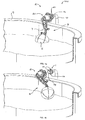
- a fill valve assembly 100 embodying the features of the present invention.
- the fill valve assembly 100 controls the flow of water into a livestock watering trough 9 to maintains the level of water in at a pre-selected level, refilling the trough 9 to the pre-selected level after the level is lowered.
- the assembly 100 includes mounting adaptor 1, a valve apparatus 2 and a float assembly 3.
- the float assembly 3 comprises a control lever 7, one end of which is attached to the valve apparatus 2 and the other to the float 6.
- Fig. 1a illustrates the fill valve assembly 100 connected by the mounting adaptor 1 to a water riser 10 in use.
- Fig. 1b illustrates the manner in which the valve apparatus 2 (and the attached float assembly 3) may be readily demounted from the mounting adaptor 1 as a unit by the twist-pull action of a bayonet coupling (as described in greater detail below) to expose the annular valve seating face 14.
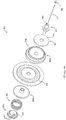
- the valve apparatus 2 comprises a two-part valve body including the cover 20 and base 21 (shown separated in Fig. 2 ) which are joined together by fasteners (not shown) to enclose a valve mechanism.
- the adaptor 1 has external screw threads 12 for mating with a threaded fitting 13 ( Figs. 1a, 1b ) by which it is fixed to the riser 10. Water is supplied from the riser 10 to the valve apparatus 2 through an axially-extending inlet passage 4 in the adaptor 1.
- the annular seating face 14 is formed at the end of a cylindrical section 16 of the adaptor 1 on which four equally angularly spaced latch tabs 15 are formed, projecting generally radially outward.
- An integrally formed radially extending rim 17 separates the cylindrical portion 16 and threaded portion 12.
- the opening 40 is formed in a latch flange 18 of the base 21 and is sized to receive the cylindrical portion of the adaptor 1.
- the latch flange 18 includes four equally angularly spaced L-shaped recesses 42, one receiving each of the latch tabs 15.
- Each recess 42 has an axially extending portion 25 into which the tabs 15 are pushed, before a turning movement rotates each tab 15 along the circumferentially extending portion 26.
- Each circumferentially extending portion 26 has an inner face cam face 43 which is inclined axially.
- the adaptor 1 is pushed into the base 21 and turned clockwise, each abutment 27 serving to limit further clockwise rotation, as well as engaging the adjacent tab 15 to bound an edge of the L-shaped recess. Anticlockwise rotation is resisted by one of four protrusions 38 extending radially out from the rim 17.
- the protrusions 38 engage with respective nubs 39 on the resilient gasket 28.
- each latching tab 15 inter-engages with a corresponding lock surface 29b of the latch flange.
- the locking faces 29a, 29b extend generally radially and resist the axial force applied to the annular seating face 14.
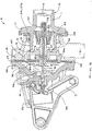
- the valve mechanism includes a pressure-responsive member in the form of diaphragm 29, the periphery 44 of which is clamped between the cover 20 and the base 21.
- the volume bounded between a first side of the diaphragm 29 and the cover 20 forms a control chamber 32.
- On the opposite side of the diaphragm 29, between the second side of the diaphragm 29 and the base 21 is an outlet chamber 45.
- the central section of the diaphragm 29 is clamped between holder 35a (received in the outlet chamber 45) and holder 35b (received in the control chamber 32).
- valve disc 8 Received in a recess 48 in the holder 35a is valve disc 8 having an annular valve surface 46 for sealing against the valve seating face 14 of the adaptor 1 to stop flow from the inlet passage 4 into the outlet chamber 45 and on through the outlet 5.
- a stem 47 extends axially through the holders 35a, 35b, diaphragm 29 and valve disc 8 and it includes a central port 30 for liquid communication between the control and outlet chambers 32, 45.
- the diaphragm assembly 50, including the stem 47, the holders 35a, 35b and the valve disc 8 are permanently connected (e.g. by press fits, or the like) to move together with the central part of the diaphragm 29 in response to variations in control pressure in the control chamber 32.
- a normally-closed pilot valve 34 is mounted in the control chamber 32 for engagement with the pivoting arm 7.
- Biasing means in the form of a compression spring 33 is received in the control chamber 32 and retained between the cover 20 and the diaphragm 29.
- the spring 33 bears against the holder 35b thereby forcing the attached valve disc 8 to its closed position where it engages the valve seating face 14, preventing water flowing to the outlet 5.
- a retainer 36, a pin 37 and a stop 38 cooperate for retaining the spring 33 and diaphragm assembly together as a unit.
- the pin 37 is received to slide in the port 30 and is fixed at one end to the retainer 36 which has an annular face 49 for abutting an end of the spring 33.
- the stop 38 is fixed (e.g. by a press fit) to the second end of the pin 37, thereby preventing the spring 33 from pulling a second end of the pin 37 through the port aperture 30.
- the valve apparatus 2 also includes a strainer 52 the centre of which is received over the end of the stem 47 and fixed by a press fit to the stop 38.
- the strainer 52 is received in the adaptor 1 and a cylindrical outer face 53 engages a corresponding inner face of the inlet passage 4 constraining all inlet water to pass through the strainer 52.
- a cap 54 is fixed by fasteners to the cover 20 and includes a slot 55 in which the pivoting arm 7 is received.
- the pivoting arm 7 connected thereto opens the pilot valve 34 which vents the control chamber 32 (the water passing through offset openings 51 in the retainer 36), such that the pressure on the inlet side overcomes the spring bias and moves the valve disc 8 to its open position. Water then flows from the inlet adaptor 1, radially out across the seating face 14 and downward through the outlet 5 into the trough 9.
- the use of the fill valve assembly 100 is best understood with reference to Figs 1a and 1b .
- the assembly 100 is mounted by the adaptor 1 through which water is supplied from the riser 10, with the control lever 7 upright.
- valve apparatus 2 and float assembly 3 can thus be demounted readily by a simple twist-and-pull movement from the adaptor 1, without any additional disassembly or the necessity to stop water supply to the riser 10.
Landscapes
- Engineering & Computer Science (AREA)
- General Engineering & Computer Science (AREA)
- Mechanical Engineering (AREA)
- Health & Medical Sciences (AREA)
- Life Sciences & Earth Sciences (AREA)
- Hydrology & Water Resources (AREA)
- Public Health (AREA)
- Water Supply & Treatment (AREA)
- Self-Closing Valves And Venting Or Aerating Valves (AREA)
- Float Valves (AREA)
Claims (3)
- Füllventilanordnung (100) zum Steuern eines Flüssigkeitsflusses in einen Behälter (9), wobei die Anordnung Folgendes umfasst:einen Adapter (1), der einen Flüssigkeitseinlassdurchgang (4) darin aufweist, und eine Ventilsitzfläche (14),eine Ventilvorrichtung (2), umfassend einen Ventilkörper (20, 21) mit einer Auslassöffnung (5) zum Leiten von Flüssigkeit in den Behälter (9) und einer Einlassöffnung (40), wobei der Adapter (1) dazu konfiguriert ist, an der Einlassöffnung (40) abbaubar an der Ventilvorrichtung (2) befestigt zu sein;wobei die Ventilvorrichtung (2) weiter ein auf Druck ansprechendes Element, das eine Membran (29) umfasst, die in dem Ventilkörper (20, 21) aufgenommen ist und in Umfangsrichtung daran befestigt ist, zwischen Abschnitten des Ventilkörpers (20, 21) umfasst, wobei die Abschnitte einen Abdeckabschnitt (20), der die Steuerkammer (32) definiert, und einen Basisabschnitt (21), in dem die Einlass- und die Auslassöffnung (40, 5) gebildet sind, umfassen,wobei die Membran (29) als Reaktion auf Änderungen eines Steuerdrucks in der Steuerkammer (32) auf einer ersten Seite der Membran (29), mit der der Flüssigkeitseinlassdurchgang (4) in Verbindung steht, bewegbar ist, wobei die Membran (29) eine zweite Seite aufweist, die ebenfalls mit dem Flüssigkeitseinlassdurchgang (4) in Verbindung steht, wobei die Membran (29) eine Ventilfläche (46) zum Dichten an der Ventilsitzfläche (14) des Adapters (1) aufweist, um den Fluss von Flüssigkeit aus dem Einlassdurchgang (4) in die Auslassöffnung (5) aufzuhalten, undein schwimmerbetätigtes Mittel, das wirksam mit dem Ventilkörper (20, 21) verbunden ist, um den Steuerdruck durch Entlüften der Steuerkammer (32) zu verändern, undVorspannmittel, umfassend eine Druckfeder (33), die auf die Membran (29) wirkt, sodass auf die erste Seite der Membran (29) wirkender Flüssigkeitsdruck zusammen mit der Druckfeder (33) wirkt, um die Ventilfläche (46) in Richtung der Ventilsitzfläche (14) des Adapters (1) zu zwängen, wobei der Ventilkörper (20, 21), die Membran (29) und die Druckfeder (33) der Ventilvorrichtung als Einheit von dem Adapter (1) abbaubar sind, die von der an dem Adapter (1) zurückbleibenden Ventilsitzfläche (14) getrennt ist,dadurch gekennzeichnet, dassdie Ventilvorrichtung (2) Haltemittel umfasst, um die Druckfeder (33) und die Membran (29) als Einheit zusammenzuhalten, wobei die Haltemittel Folgendes umfassen: einen Halter (36) zum Anliegen an einem Ende der Druckfeder (33), der die Druckfeder zwischen dem Abdeckabschnitt (20) des Ventilkörpers und der Membran hält; einen Stift (37) mit einem an dem Halter (36) befestigten ersten Ende, wobei sich der Stift (37) durch die Druckfeder (33) hindurch erstreckt und zum Gleiten in einer Öffnung (30) in der Membran (29) aufgenommen ist, und einen Anschlag (38), um zu verhindern, dass die Druckfeder ein zweites Ende des Stifts (37) durch die Öffnung (30) in der Membran (29) hindurch zieht, wobei die Ventilvorrichtung weiter einen Verriegelungsflansch (18), der an einem von dem Adapter (1) und dem Ventilkörper (20, 21) vorgesehen ist, und damit zusammenwirkende Verriegelungslaschen (15) am anderen von dem Adapter (1) und dem Ventilkörper (20, 21) umfasst, wobei der Verriegelungsflansch (18) und eine damit zusammenpassende der Verriegelungslaschen (15) ineinander eingreifende Sperrflächen (29a, 29b) definieren, wobei die Sperrflächen (29a, 29b) von der Druckfeder (33) aufeinander zu gedrängt werden während die Ventilfläche (46) an die Sitzfläche (14) gehalten wird.
- Ventilanordnung (100) nach Anspruch 1, wobei der Verriegelungsflansch (18) eine L-förmige Aussparung einer Bajonettverbindung zum Aufnehmen jeder Lasche (15) definiert, um zu ermöglichen, dass der Ventilkörper (20, 21) durch einen Druck-Drehvorgang mit dem Adapter (1) verbunden wird.
- Ventilanordnung (100) nach einem der Ansprüche 1 oder 2, weiter umfassend eine an der Membran (29) befestigte Dichtungsscheibe (8), wobei die Ventilfläche (46) zum Dichten an der Sitzfläche (14) an der Dichtungsscheibe (8) vorgesehen ist.
Applications Claiming Priority (1)
| Application Number | Priority Date | Filing Date | Title |
|---|---|---|---|
| NZ536133A NZ536133A (en) | 2004-10-26 | 2004-10-26 | Valve |
Publications (2)
| Publication Number | Publication Date |
|---|---|
| EP1653016A1 EP1653016A1 (de) | 2006-05-03 |
| EP1653016B1 true EP1653016B1 (de) | 2018-02-28 |
Family
ID=35789027
Family Applications (1)
| Application Number | Title | Priority Date | Filing Date |
|---|---|---|---|
| EP05256611.4A Expired - Lifetime EP1653016B1 (de) | 2004-10-26 | 2005-10-25 | Schnell ausbaubares Einlassventil |
Country Status (3)
| Country | Link |
|---|---|
| US (1) | US7647938B2 (de) |
| EP (1) | EP1653016B1 (de) |
| NZ (1) | NZ536133A (de) |
Families Citing this family (9)
| Publication number | Priority date | Publication date | Assignee | Title |
|---|---|---|---|---|
| CN102466045B (zh) * | 2010-11-11 | 2013-11-06 | 李飞宇 | 一种马桶进水阀及其控制方法 |
| AU2013226638B2 (en) * | 2012-03-02 | 2016-10-20 | Apex Valves Limited | A liquid control valve |
| AU2012258328B2 (en) * | 2012-08-30 | 2017-10-05 | Goodnature Limited | Animal traps and trigger mechanisms |
| AU2013273691B2 (en) * | 2012-12-21 | 2018-01-18 | Apex Valves Limited | Excess Pressure Safety Relief Valve |
| US20140373934A1 (en) * | 2013-06-20 | 2014-12-25 | Jobe Holdings Limited | Attachment for float valve and method of use |
| JP5639732B1 (ja) * | 2014-09-17 | 2014-12-10 | 兼工業株式会社 | ボールタップ |
| US11716968B2 (en) * | 2017-10-04 | 2023-08-08 | Ritchie Industries, Inc. | Waterer valve system |
| US20210332579A1 (en) * | 2020-04-24 | 2021-10-28 | Fluidmaster, Inc. | Exchangeable fill valve system and methods |
| US20260022778A1 (en) * | 2024-07-19 | 2026-01-22 | Shenzhen Rongcheng Innovation Technology Co., LTD | Automatic control water valve and automatic water feeder |
Citations (1)
| Publication number | Priority date | Publication date | Assignee | Title |
|---|---|---|---|---|
| US20020000248A1 (en) * | 2000-06-28 | 2002-01-03 | Herlihy Geoffrey Francis | Valve |
Family Cites Families (11)
| Publication number | Priority date | Publication date | Assignee | Title |
|---|---|---|---|---|
| US3429321A (en) * | 1968-01-02 | 1969-02-25 | American Meter Co | Safety valve actuator |
| US3982557A (en) * | 1974-05-20 | 1976-09-28 | Ignacio Acevedo | Fluid valve with float actuator |
| US3971405A (en) * | 1974-07-15 | 1976-07-27 | Parker-Hannifin Corporation | Pressure controlled hydrant valve coupler |
| SE417739B (sv) * | 1977-08-12 | 1981-04-06 | Forsman & Co Stifo Handelsbola | Utloppsanordning vid aterfyllningsventil for klosettspolcisterner |
| US4240606A (en) * | 1979-06-12 | 1980-12-23 | Jh Industries, Inc. | Fill valve |
| US4488702A (en) * | 1983-09-29 | 1984-12-18 | Lapeyre James M | Rolling diaphragm metering valve |
| US4632142A (en) * | 1985-01-04 | 1986-12-30 | Shames Sidney J | Ballcock assembly |
| US5282280A (en) * | 1993-01-26 | 1994-02-01 | Josef Wodeslavsky | Toilet water reservoir inlet and outlet control valve |
| US5842498A (en) * | 1995-06-07 | 1998-12-01 | Locke; Randal D. A. | Mounting adapter and assembly for rendering fill valves for tank-type instantly dismountable |
| US5652970A (en) * | 1996-06-06 | 1997-08-05 | Wodeslavsky; Josef | Toilet water reservoir water dumping valve for sealing the reservoir's water outlet by hydraulic pressure, and controlling water volume |
| NZ328862A (en) | 1997-09-26 | 1998-11-25 | Apex Valves Ltd | Float valve comprising a passage between inlet and chamber venting to the atmosphere and a flexible member displaceable under pressure at the inlet to open the valve |
-
2004
- 2004-10-26 NZ NZ536133A patent/NZ536133A/en not_active IP Right Cessation
-
2005
- 2005-10-25 EP EP05256611.4A patent/EP1653016B1/de not_active Expired - Lifetime
- 2005-10-26 US US11/259,359 patent/US7647938B2/en active Active
Patent Citations (1)
| Publication number | Priority date | Publication date | Assignee | Title |
|---|---|---|---|---|
| US20020000248A1 (en) * | 2000-06-28 | 2002-01-03 | Herlihy Geoffrey Francis | Valve |
Also Published As
| Publication number | Publication date |
|---|---|
| EP1653016A1 (de) | 2006-05-03 |
| US7647938B2 (en) | 2010-01-19 |
| US20060124878A1 (en) | 2006-06-15 |
| NZ536133A (en) | 2006-05-26 |
Similar Documents
| Publication | Publication Date | Title |
|---|---|---|
| US4529515A (en) | Valve | |
| JP3804949B2 (ja) | 流体フィルタ及びそのドレン機構、流体フィルタに使用されるドレン用冶具並びに流体フィルタのドレン方法 | |
| US8097156B2 (en) | Fluid filtration system | |
| EP1653016B1 (de) | Schnell ausbaubares Einlassventil | |
| US20070284296A1 (en) | Filter cartridge and head assembly with internal shutoff valve | |
| US11536387B2 (en) | Serviceable valve carousel system | |
| JP4190383B2 (ja) | 流体フィルタ及びそのドレン機構、流体フィルタに使用されるドレン用冶具並びに流体フィルタのドレン方法 | |
| US4858959A (en) | Fuel line adaptor | |
| JPH11294135A (ja) | エンジンのオイル抜き用プラグ | |
| EP0961892B1 (de) | Schwimmerventil für einen toilettenspülkasten | |
| JP2003247267A (ja) | ストレーナ収容部材を備えた給水構造 | |
| WO2009005499A1 (en) | Filter cartridge and head assembly with internal shutoff valve | |
| JP7486702B2 (ja) | 逆止弁 | |
| CN220354480U (zh) | 一种阀芯 | |
| KR200179235Y1 (ko) | 버터플라이밸브를 갖춘 스트레이너 | |
| GB1588216A (en) | Fluid flow control device | |
| JP2006175441A (ja) | 流体フィルタ及びそのドレン機構、流体フィルタに使用されるドレン用冶具並びに流体フィルタのドレン方法 | |
| PL197244B1 (pl) | Upustowy zawór membranowy sterowany ciśnieniowo | |
| JPH0537015Y2 (de) | ||
| EP1683996A1 (de) | Filter für ein schwimmergesteuertes Füllventil | |
| WO2026024881A1 (en) | Water filtration assembly | |
| JP2026045908A (ja) | ストレーナ内蔵ボール弁装置 | |
| AU2005200208A1 (en) | Water meter assemblies | |
| JPH1151248A (ja) | キャップ付き止水栓 | |
| NZ230940A (en) | Liquid control device with changeable filter bowl: non return valve prevents backflow of liquid |
Legal Events
| Date | Code | Title | Description |
|---|---|---|---|
| PUAI | Public reference made under article 153(3) epc to a published international application that has entered the european phase |
Free format text: ORIGINAL CODE: 0009012 |
|
| AK | Designated contracting states |
Kind code of ref document: A1 Designated state(s): AT BE BG CH CY CZ DE DK EE ES FI FR GB GR HU IE IS IT LI LT LU LV MC NL PL PT RO SE SI SK TR |
|
| AX | Request for extension of the european patent |
Extension state: AL BA HR MK YU |
|
| 17P | Request for examination filed |
Effective date: 20061024 |
|
| 17Q | First examination report despatched |
Effective date: 20061121 |
|
| AKX | Designation fees paid |
Designated state(s): AT BE BG CH CY CZ DE DK EE ES FI FR GB GR HU IE IS IT LI LT LU LV MC NL PL PT RO SE SI SK TR |
|
| GRAP | Despatch of communication of intention to grant a patent |
Free format text: ORIGINAL CODE: EPIDOSNIGR1 |
|
| STAA | Information on the status of an ep patent application or granted ep patent |
Free format text: STATUS: GRANT OF PATENT IS INTENDED |
|
| RIC1 | Information provided on ipc code assigned before grant |
Ipc: F16K 31/385 20060101ALI20171013BHEP Ipc: E03D 1/32 20060101AFI20171013BHEP Ipc: F16K 31/34 20060101ALI20171013BHEP |
|
| INTG | Intention to grant announced |
Effective date: 20171114 |
|
| GRAS | Grant fee paid |
Free format text: ORIGINAL CODE: EPIDOSNIGR3 |
|
| GRAA | (expected) grant |
Free format text: ORIGINAL CODE: 0009210 |
|
| STAA | Information on the status of an ep patent application or granted ep patent |
Free format text: STATUS: THE PATENT HAS BEEN GRANTED |
|
| AK | Designated contracting states |
Kind code of ref document: B1 Designated state(s): AT BE BG CH CY CZ DE DK EE ES FI FR GB GR HU IE IS IT LI LT LU LV MC NL PL PT RO SE SI SK TR |
|
| REG | Reference to a national code |
Ref country code: GB Ref legal event code: FG4D Ref country code: CH Ref legal event code: EP |
|
| REG | Reference to a national code |
Ref country code: AT Ref legal event code: REF Ref document number: 974289 Country of ref document: AT Kind code of ref document: T Effective date: 20180315 |
|
| REG | Reference to a national code |
Ref country code: IE Ref legal event code: FG4D |
|
| REG | Reference to a national code |
Ref country code: DE Ref legal event code: R096 Ref document number: 602005053560 Country of ref document: DE |
|
| REG | Reference to a national code |
Ref country code: NL Ref legal event code: MP Effective date: 20180228 |
|
| REG | Reference to a national code |
Ref country code: LT Ref legal event code: MG4D |
|
| REG | Reference to a national code |
Ref country code: AT Ref legal event code: MK05 Ref document number: 974289 Country of ref document: AT Kind code of ref document: T Effective date: 20180228 |
|
| PG25 | Lapsed in a contracting state [announced via postgrant information from national office to epo] |
Ref country code: ES Free format text: LAPSE BECAUSE OF FAILURE TO SUBMIT A TRANSLATION OF THE DESCRIPTION OR TO PAY THE FEE WITHIN THE PRESCRIBED TIME-LIMIT Effective date: 20180228 Ref country code: LT Free format text: LAPSE BECAUSE OF FAILURE TO SUBMIT A TRANSLATION OF THE DESCRIPTION OR TO PAY THE FEE WITHIN THE PRESCRIBED TIME-LIMIT Effective date: 20180228 Ref country code: CY Free format text: LAPSE BECAUSE OF FAILURE TO SUBMIT A TRANSLATION OF THE DESCRIPTION OR TO PAY THE FEE WITHIN THE PRESCRIBED TIME-LIMIT Effective date: 20180228 Ref country code: NL Free format text: LAPSE BECAUSE OF FAILURE TO SUBMIT A TRANSLATION OF THE DESCRIPTION OR TO PAY THE FEE WITHIN THE PRESCRIBED TIME-LIMIT Effective date: 20180228 Ref country code: FI Free format text: LAPSE BECAUSE OF FAILURE TO SUBMIT A TRANSLATION OF THE DESCRIPTION OR TO PAY THE FEE WITHIN THE PRESCRIBED TIME-LIMIT Effective date: 20180228 |
|
| PG25 | Lapsed in a contracting state [announced via postgrant information from national office to epo] |
Ref country code: AT Free format text: LAPSE BECAUSE OF FAILURE TO SUBMIT A TRANSLATION OF THE DESCRIPTION OR TO PAY THE FEE WITHIN THE PRESCRIBED TIME-LIMIT Effective date: 20180228 Ref country code: GR Free format text: LAPSE BECAUSE OF FAILURE TO SUBMIT A TRANSLATION OF THE DESCRIPTION OR TO PAY THE FEE WITHIN THE PRESCRIBED TIME-LIMIT Effective date: 20180529 Ref country code: BG Free format text: LAPSE BECAUSE OF FAILURE TO SUBMIT A TRANSLATION OF THE DESCRIPTION OR TO PAY THE FEE WITHIN THE PRESCRIBED TIME-LIMIT Effective date: 20180528 Ref country code: LV Free format text: LAPSE BECAUSE OF FAILURE TO SUBMIT A TRANSLATION OF THE DESCRIPTION OR TO PAY THE FEE WITHIN THE PRESCRIBED TIME-LIMIT Effective date: 20180228 Ref country code: SE Free format text: LAPSE BECAUSE OF FAILURE TO SUBMIT A TRANSLATION OF THE DESCRIPTION OR TO PAY THE FEE WITHIN THE PRESCRIBED TIME-LIMIT Effective date: 20180228 |
|
| REG | Reference to a national code |
Ref country code: FR Ref legal event code: PLFP Year of fee payment: 14 |
|
| PG25 | Lapsed in a contracting state [announced via postgrant information from national office to epo] |
Ref country code: RO Free format text: LAPSE BECAUSE OF FAILURE TO SUBMIT A TRANSLATION OF THE DESCRIPTION OR TO PAY THE FEE WITHIN THE PRESCRIBED TIME-LIMIT Effective date: 20180228 Ref country code: PL Free format text: LAPSE BECAUSE OF FAILURE TO SUBMIT A TRANSLATION OF THE DESCRIPTION OR TO PAY THE FEE WITHIN THE PRESCRIBED TIME-LIMIT Effective date: 20180228 Ref country code: EE Free format text: LAPSE BECAUSE OF FAILURE TO SUBMIT A TRANSLATION OF THE DESCRIPTION OR TO PAY THE FEE WITHIN THE PRESCRIBED TIME-LIMIT Effective date: 20180228 |
|
| REG | Reference to a national code |
Ref country code: DE Ref legal event code: R097 Ref document number: 602005053560 Country of ref document: DE |
|
| PG25 | Lapsed in a contracting state [announced via postgrant information from national office to epo] |
Ref country code: DK Free format text: LAPSE BECAUSE OF FAILURE TO SUBMIT A TRANSLATION OF THE DESCRIPTION OR TO PAY THE FEE WITHIN THE PRESCRIBED TIME-LIMIT Effective date: 20180228 Ref country code: CZ Free format text: LAPSE BECAUSE OF FAILURE TO SUBMIT A TRANSLATION OF THE DESCRIPTION OR TO PAY THE FEE WITHIN THE PRESCRIBED TIME-LIMIT Effective date: 20180228 Ref country code: SK Free format text: LAPSE BECAUSE OF FAILURE TO SUBMIT A TRANSLATION OF THE DESCRIPTION OR TO PAY THE FEE WITHIN THE PRESCRIBED TIME-LIMIT Effective date: 20180228 |
|
| PLBE | No opposition filed within time limit |
Free format text: ORIGINAL CODE: 0009261 |
|
| STAA | Information on the status of an ep patent application or granted ep patent |
Free format text: STATUS: NO OPPOSITION FILED WITHIN TIME LIMIT |
|
| 26N | No opposition filed |
Effective date: 20181129 |
|
| PG25 | Lapsed in a contracting state [announced via postgrant information from national office to epo] |
Ref country code: SI Free format text: LAPSE BECAUSE OF FAILURE TO SUBMIT A TRANSLATION OF THE DESCRIPTION OR TO PAY THE FEE WITHIN THE PRESCRIBED TIME-LIMIT Effective date: 20180228 |
|
| REG | Reference to a national code |
Ref country code: CH Ref legal event code: PL |
|
| REG | Reference to a national code |
Ref country code: BE Ref legal event code: MM Effective date: 20181031 |
|
| PG25 | Lapsed in a contracting state [announced via postgrant information from national office to epo] |
Ref country code: LU Free format text: LAPSE BECAUSE OF NON-PAYMENT OF DUE FEES Effective date: 20181025 Ref country code: MC Free format text: LAPSE BECAUSE OF FAILURE TO SUBMIT A TRANSLATION OF THE DESCRIPTION OR TO PAY THE FEE WITHIN THE PRESCRIBED TIME-LIMIT Effective date: 20180228 |
|
| REG | Reference to a national code |
Ref country code: IE Ref legal event code: MM4A |
|
| PG25 | Lapsed in a contracting state [announced via postgrant information from national office to epo] |
Ref country code: CH Free format text: LAPSE BECAUSE OF NON-PAYMENT OF DUE FEES Effective date: 20181031 Ref country code: LI Free format text: LAPSE BECAUSE OF NON-PAYMENT OF DUE FEES Effective date: 20181031 Ref country code: BE Free format text: LAPSE BECAUSE OF NON-PAYMENT OF DUE FEES Effective date: 20181031 |
|
| PG25 | Lapsed in a contracting state [announced via postgrant information from national office to epo] |
Ref country code: IE Free format text: LAPSE BECAUSE OF NON-PAYMENT OF DUE FEES Effective date: 20181025 |
|
| PG25 | Lapsed in a contracting state [announced via postgrant information from national office to epo] |
Ref country code: TR Free format text: LAPSE BECAUSE OF FAILURE TO SUBMIT A TRANSLATION OF THE DESCRIPTION OR TO PAY THE FEE WITHIN THE PRESCRIBED TIME-LIMIT Effective date: 20180228 |
|
| PG25 | Lapsed in a contracting state [announced via postgrant information from national office to epo] |
Ref country code: PT Free format text: LAPSE BECAUSE OF FAILURE TO SUBMIT A TRANSLATION OF THE DESCRIPTION OR TO PAY THE FEE WITHIN THE PRESCRIBED TIME-LIMIT Effective date: 20180228 |
|
| PG25 | Lapsed in a contracting state [announced via postgrant information from national office to epo] |
Ref country code: HU Free format text: LAPSE BECAUSE OF FAILURE TO SUBMIT A TRANSLATION OF THE DESCRIPTION OR TO PAY THE FEE WITHIN THE PRESCRIBED TIME-LIMIT; INVALID AB INITIO Effective date: 20051025 |
|
| PG25 | Lapsed in a contracting state [announced via postgrant information from national office to epo] |
Ref country code: IS Free format text: LAPSE BECAUSE OF FAILURE TO SUBMIT A TRANSLATION OF THE DESCRIPTION OR TO PAY THE FEE WITHIN THE PRESCRIBED TIME-LIMIT Effective date: 20180628 |
|
| PGFP | Annual fee paid to national office [announced via postgrant information from national office to epo] |
Ref country code: DE Payment date: 20241029 Year of fee payment: 20 |
|
| PGFP | Annual fee paid to national office [announced via postgrant information from national office to epo] |
Ref country code: GB Payment date: 20241022 Year of fee payment: 20 |
|
| PGFP | Annual fee paid to national office [announced via postgrant information from national office to epo] |
Ref country code: FR Payment date: 20241025 Year of fee payment: 20 |
|
| PGFP | Annual fee paid to national office [announced via postgrant information from national office to epo] |
Ref country code: IT Payment date: 20241022 Year of fee payment: 20 |
|
| REG | Reference to a national code |
Ref country code: DE Ref legal event code: R071 Ref document number: 602005053560 Country of ref document: DE |
|
| REG | Reference to a national code |
Ref country code: GB Ref legal event code: PE20 Expiry date: 20251024 |