EP1652740A2 - Outwardly deploying air bag system - Google Patents
Outwardly deploying air bag system Download PDFInfo
- Publication number
- EP1652740A2 EP1652740A2 EP05020685A EP05020685A EP1652740A2 EP 1652740 A2 EP1652740 A2 EP 1652740A2 EP 05020685 A EP05020685 A EP 05020685A EP 05020685 A EP05020685 A EP 05020685A EP 1652740 A2 EP1652740 A2 EP 1652740A2
- Authority
- EP
- European Patent Office
- Prior art keywords
- air bag
- gas
- internal pressure
- pedestrian
- outwardly deploying
- Prior art date
- Legal status (The legal status is an assumption and is not a legal conclusion. Google has not performed a legal analysis and makes no representation as to the accuracy of the status listed.)
- Granted
Links
- 238000002347 injection Methods 0.000 abstract description 6
- 239000007924 injection Substances 0.000 abstract description 6
- 238000001514 detection method Methods 0.000 abstract description 3
- 239000004744 fabric Substances 0.000 description 5
- 230000007423 decrease Effects 0.000 description 2
- 230000003247 decreasing effect Effects 0.000 description 2
- 238000009958 sewing Methods 0.000 description 2
- 238000010521 absorption reaction Methods 0.000 description 1
- 230000002401 inhibitory effect Effects 0.000 description 1
Images

Classifications
-
- B—PERFORMING OPERATIONS; TRANSPORTING
- B60—VEHICLES IN GENERAL
- B60R—VEHICLES, VEHICLE FITTINGS, OR VEHICLE PARTS, NOT OTHERWISE PROVIDED FOR
- B60R21/00—Arrangements or fittings on vehicles for protecting or preventing injuries to occupants or pedestrians in case of accidents or other traffic risks
- B60R21/34—Protecting non-occupants of a vehicle, e.g. pedestrians
- B60R21/36—Protecting non-occupants of a vehicle, e.g. pedestrians using airbags
-
- B—PERFORMING OPERATIONS; TRANSPORTING
- B60—VEHICLES IN GENERAL
- B60R—VEHICLES, VEHICLE FITTINGS, OR VEHICLE PARTS, NOT OTHERWISE PROVIDED FOR
- B60R21/00—Arrangements or fittings on vehicles for protecting or preventing injuries to occupants or pedestrians in case of accidents or other traffic risks
- B60R21/02—Occupant safety arrangements or fittings, e.g. crash pads
- B60R21/16—Inflatable occupant restraints or confinements designed to inflate upon impact or impending impact, e.g. air bags
- B60R21/26—Inflatable occupant restraints or confinements designed to inflate upon impact or impending impact, e.g. air bags characterised by the inflation fluid source or means to control inflation fluid flow
- B60R2021/26058—Inflatable occupant restraints or confinements designed to inflate upon impact or impending impact, e.g. air bags characterised by the inflation fluid source or means to control inflation fluid flow using a combination of inflators
-
- B—PERFORMING OPERATIONS; TRANSPORTING
- B60—VEHICLES IN GENERAL
- B60R—VEHICLES, VEHICLE FITTINGS, OR VEHICLE PARTS, NOT OTHERWISE PROVIDED FOR
- B60R21/00—Arrangements or fittings on vehicles for protecting or preventing injuries to occupants or pedestrians in case of accidents or other traffic risks
- B60R21/02—Occupant safety arrangements or fittings, e.g. crash pads
- B60R21/16—Inflatable occupant restraints or confinements designed to inflate upon impact or impending impact, e.g. air bags
- B60R21/23—Inflatable members
- B60R21/239—Inflatable members characterised by their venting means
Definitions
- the present invention relates to an outwardly deploying air bag system that protects a pedestrian, or a passenger of a bicycle or a motorcycle (hereinafter also referred to as a pedestrian or the like) when a vehicle collides with, for example, the pedestrian, the bicycle, or the motorcycle during driving.
- Outwardly deploying air bag systems have been developed as pedestrian-protecting air bag systems that prevent a pedestrian or the like from directly hitting, for example, a wind shield by deploying an air bag along an outer surface of a vehicle body in order to protect the pedestrian or the like when a moving vehicle collides with, for example, the pedestrian, a bicycle, or a motorcycle.
- Patent Document 1 JP-A-8-276816 describes an outwardly deploying air bag system in which the internal pressure of an air bag increases as the speed of a car increases. This publication also discloses a mechanism that increases the inflation internal pressure of the air bag by reducing the internal capacity of the air bag, and discloses that the internal pressure of the air bag is decreased by inhibiting a part of gas from an inflator from being filled in the air bag.
- vent holes are provided in an air bag of an outwardly deploying air bag system, as is described in, for example, JP-A-2001-315599 (Patent Document 2).
- the air bag described in JP-A-8-276816 does not have a vent hole, and the internal pressure of the inflated air bag is kept high for a relatively long period.
- gas does not leak from the vent hole when a pedestrian or the like hits the air bag, and therefore, a sufficient impact absorption property is not necessarily ensured.
- the air bag When the air bag is provided with a vent hole, gas leaks from the air bag through the vent hole. Therefore, it is preferable to increase the output of the inflator in expectation of gas leakage. In this case, however, the maximum internal pressure of the inflated air bag vainly increases. Consequently, an impact on the pedestrian or the like cannot be sufficiently reduced, and, for example, the sewing cost and base-cloth cost of the air bag are increased.
- An object of the present invention is to provide an outwardly deploying air bag system that can maintain the internal pressure of an air bag for a required period without vainly increasing the maximum internal pressure of the air bag during inflation.
- An outwardly deploying air bag system according to the present invention includes an air bag deployable along an outer surface of an automobile, and a gas generating means for inflating the air bag.
- the gas generating means generates gas at a plurality of different times.
- the air bag has a vent means through which the gas leaks from the interior of the air bag to absorb an impact.
- the gas generating means performs a first gas generation step to inflate the air bag, and performs a second gas generation step when the internal pressure of the air bag falls to a predetermined pressure after reaching the maximum value.
- the gas generating means since the gas generating means generates gas at a plurality of different times, the internal pressure of the air bag can be kept high for a required period. It is also possible to limit the amount of gas generated by the gas generating means in one step, and to lower the maximum internal pressure of the inflated air bag. Consequently, an impact on the pedestrian or the like can be reduced sufficiently, and the production cost of the air bag can be reduced.
- the present invention is suitably applied to a case in which there is a vent means through which gas leaks from the air bag.
- the vent means such as a vent hole
- gas partly leaks from the air bag and the maximum internal pressure of the air bag is decreased, before a pedestrian or the like hits the air bag.
- the present invention by performing the second and subsequent gas generation steps after the air bag is inflated, the gas leaking through the vent means is compensated for, and the internal pressure of the air bag can be kept high for a long period.
- the air bag is inflated in the first gas generation step, and the second gas generation step is performed when the internal pressure of the air bag falls to a predetermined pressure after reaching the maximum value. Therefore, an impact on the pedestrian or the like can be absorbed quite sufficiently.
- An outwardly deploying air bag system 1 includes a container-shaped retainer (air-bag holding member) 2 serving as a case having an upper opening, an air bag 3 placed inside the retainer 2 in a folded manner, a protection cloth 4 that covers the folded air bag 3, an inflator 5 for inflating the air bag 3, and a lid (cover member) 6 that covers the upper opening of the retainer 2.
- the inflator 5 is of a multistage type that injects gas in two steps, and two pairs of ignition harnesses 5a and 5b are connected thereto.
- the air bag 3 has vent holes 3a.
- a tear line 6a formed of a groove is provided on a back surface of the lid 6.
- the air bag 3 is inflated, when a pressing force stronger than a predetermined force is applied to the back surface of the lid 6 by the inflation pressure of the air bag 3, the lid 6 is torn along the tear line 6a, and starts to open outward.
- the air bag 3 and the protection cloth 4 are attached to the retainer 2 by ring retainers 7, bolts 8, and nuts 9.
- the inflator 5 is also attached to the retainer 2 by the volts 8 and the nuts 9.
- a gas injecting portion at the head of the inflator 5 is placed inside the air bag 3.
- the lid 6 is attached to the retainer 2 by rivets 10.
- the inflator 5 when at least one of a collision predicting sensor and a collision detection sensor predicts or detects a collision with, for example, a pedestrian or the like, the inflator 5 is caused to inject gas in a first step, and the air bag 3 is inflated by the gas from the inflator 5.
- the lid 6 When the air bag 3 starts inflation, the lid 6 is torn along the tear line 6a by the inflation pressure of the air bag 3, and the air bag 3 is deployed along an outer surface 12 of a vehicle body, as shown in Fig. 1(b).
- the inflator 5 injects gas in two steps.
- the inflator 5 injects gas in the first step, as described above. Consequently, the air bag 3 is inflated and deployed into a final deployment shape.
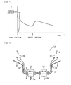
- the internal pressure of the air bag 3 becomes the highest, as shown in Fig. 2. Subsequently, the internal pressure of the air bag 3 gradually decreases as the gas in the air bag 3 leaks through the vent holes 3a.
- the inflator 5 is caused to inject gas in the second step when the internal pressure of the air bag 3 falls to a predetermined pressure (for example, when approximately 70 msec to 120 msec passes from the beginning of the first gas injection step).
- the internal pressure of the air bag 3 is thereby increased again, as shown in Fig. 2.
- the internal pressure of the air bag 3 gradually decreases again.
- the internal pressure of the air bag 3 can be kept high for a long period, and an impact can be sufficiently absorbed at any time point when a pedestrian or the like hits the air bag 3.
- the internal pressure of the air bag is kept high for a long period by the second gas injection step, and it is satisfactory as long as the pressure and amount of the gas injected in the first step can deploy the air bag 3 into the final deployment shape within a predetermined period.
- the maximum internal pressure obtained when the air bag 3 is inflated into the final deployment shape is lower than before. Therefore, an impact on a pedestrian or the like can be sufficiently reduced, the strength of a base cloth of the air bag 3 and the required strength of a joint portion, such as a sewn portion, can be reduced, and the production cost of the air bag 3 can be reduced.
- the inflator 5 injects gas in two steps in this embodiment, it may inject gas in three or more steps.
- a plurality of inflators 5A and 5B may be provided as in an outwardly deploying air bag system 1A shown in Fig. 3, and the internal pressure may be kept high for a long period by igniting the inflators 5A and 5B at different time points.
- gas may leak through sewing stitches of the air bag 3, instead leaking through the vent holes of the air bag 3.
- gas may leak through a breathable base cloth that forms the air bag.
Landscapes
- Engineering & Computer Science (AREA)
- Mechanical Engineering (AREA)
- Air Bags (AREA)
Abstract
Description
- The present invention relates to an outwardly deploying air bag system that protects a pedestrian, or a passenger of a bicycle or a motorcycle (hereinafter also referred to as a pedestrian or the like) when a vehicle collides with, for example, the pedestrian, the bicycle, or the motorcycle during driving.
- Outwardly deploying air bag systems have been developed as pedestrian-protecting air bag systems that prevent a pedestrian or the like from directly hitting, for example, a wind shield by deploying an air bag along an outer surface of a vehicle body in order to protect the pedestrian or the like when a moving vehicle collides with, for example, the pedestrian, a bicycle, or a motorcycle.
- When the internal pressure of an outwardly deploying air bag inflated along the outer surface of the vehicle body is excessively high or excessively low, an impact on the pedestrian or the like cannot be reduced sufficiently.
- JP-A-8-276816 (Patent Document 1) describes an outwardly deploying air bag system in which the internal pressure of an air bag increases as the speed of a car increases. This publication also discloses a mechanism that increases the inflation internal pressure of the air bag by reducing the internal capacity of the air bag, and discloses that the internal pressure of the air bag is decreased by inhibiting a part of gas from an inflator from being filled in the air bag.
- It is known that vent holes are provided in an air bag of an outwardly deploying air bag system, as is described in, for example, JP-A-2001-315599 (Patent Document 2).
- The air bag described in JP-A-8-276816 does not have a vent hole, and the internal pressure of the inflated air bag is kept high for a relatively long period. In this type of air bag, gas does not leak from the vent hole when a pedestrian or the like hits the air bag, and therefore, a sufficient impact absorption property is not necessarily ensured.
- When the air bag is provided with a vent hole, gas leaks from the air bag through the vent hole. Therefore, it is preferable to increase the output of the inflator in expectation of gas leakage. In this case, however, the maximum internal pressure of the inflated air bag vainly increases. Consequently, an impact on the pedestrian or the like cannot be sufficiently reduced, and, for example, the sewing cost and base-cloth cost of the air bag are increased.
- An object of the present invention is to provide an outwardly deploying air bag system that can maintain the internal pressure of an air bag for a required period without vainly increasing the maximum internal pressure of the air bag during inflation.
- An outwardly deploying air bag system according to the present invention (claim 1) includes an air bag deployable along an outer surface of an automobile, and a gas generating means for inflating the air bag. The gas generating means generates gas at a plurality of different times.
- In an outwardly deploying air bag system claimed in
claim 2, according to claim 1, the air bag has a vent means through which the gas leaks from the interior of the air bag to absorb an impact. - In an outwardly deploying air bag system claimed in claim 3, according to
claim 2, the gas generating means performs a first gas generation step to inflate the air bag, and performs a second gas generation step when the internal pressure of the air bag falls to a predetermined pressure after reaching the maximum value. - In the outwardly deploying air bag system of the present invention, since the gas generating means generates gas at a plurality of different times, the internal pressure of the air bag can be kept high for a required period. It is also possible to limit the amount of gas generated by the gas generating means in one step, and to lower the maximum internal pressure of the inflated air bag. Consequently, an impact on the pedestrian or the like can be reduced sufficiently, and the production cost of the air bag can be reduced.
- The present invention is suitably applied to a case in which there is a vent means through which gas leaks from the air bag. When the vent means, such as a vent hole, is provided, gas partly leaks from the air bag and the maximum internal pressure of the air bag is decreased, before a pedestrian or the like hits the air bag. According to the present invention, by performing the second and subsequent gas generation steps after the air bag is inflated, the gas leaking through the vent means is compensated for, and the internal pressure of the air bag can be kept high for a long period.
- In the present invention, the air bag is inflated in the first gas generation step, and the second gas generation step is performed when the internal pressure of the air bag falls to a predetermined pressure after reaching the maximum value. Therefore, an impact on the pedestrian or the like can be absorbed quite sufficiently.
- An embodiment of the present invention will be described below with reference to the drawings:
- Figs. 1(a) and 1(b) are cross-sectional views of an outwardly deploying air bag system according to an embodiment of the invention showing a state before an air bag is inflated and a state after the air bag is inflated, respectively;
- Fig. 2 is a graph showing the change of the internal pressure of an air bag with time in the outwardly deploying air bag system shown in Fig. 1; and
- Fig. 3 is a cross-sectional view of an outwardly deploying air bag system according to another embodiment when an inflator operates.
- An outwardly deploying air bag system 1 includes a container-shaped retainer (air-bag holding member) 2 serving as a case having an upper opening, an air bag 3 placed inside the
retainer 2 in a folded manner, aprotection cloth 4 that covers the folded air bag 3, aninflator 5 for inflating the air bag 3, and a lid (cover member) 6 that covers the upper opening of theretainer 2. - The
inflator 5 is of a multistage type that injects gas in two steps, and two pairs ofignition harnesses vent holes 3a. - A
tear line 6a formed of a groove is provided on a back surface of thelid 6. In a case in which the air bag 3 is inflated, when a pressing force stronger than a predetermined force is applied to the back surface of thelid 6 by the inflation pressure of the air bag 3, thelid 6 is torn along thetear line 6a, and starts to open outward. - The air bag 3 and the
protection cloth 4 are attached to theretainer 2 byring retainers 7,bolts 8, andnuts 9. Theinflator 5 is also attached to theretainer 2 by thevolts 8 and thenuts 9. A gas injecting portion at the head of theinflator 5 is placed inside the air bag 3. Thelid 6 is attached to theretainer 2 byrivets 10. - In the outwardly deploying air bag system 1 having this configuration, when at least one of a collision predicting sensor and a collision detection sensor predicts or detects a collision with, for example, a pedestrian or the like, the
inflator 5 is caused to inject gas in a first step, and the air bag 3 is inflated by the gas from theinflator 5. - When the air bag 3 starts inflation, the
lid 6 is torn along thetear line 6a by the inflation pressure of the air bag 3, and the air bag 3 is deployed along anouter surface 12 of a vehicle body, as shown in Fig. 1(b). - In this embodiment, the
inflator 5 injects gas in two steps. When a collision with a pedestrian or the like is detected, theinflator 5 injects gas in the first step, as described above. Consequently, the air bag 3 is inflated and deployed into a final deployment shape. When the air bag 3 takes the final deployment shape, the internal pressure of the air bag 3 becomes the highest, as shown in Fig. 2. Subsequently, the internal pressure of the air bag 3 gradually decreases as the gas in the air bag 3 leaks through thevent holes 3a. - In this embodiment, the
inflator 5 is caused to inject gas in the second step when the internal pressure of the air bag 3 falls to a predetermined pressure (for example, when approximately 70 msec to 120 msec passes from the beginning of the first gas injection step). The internal pressure of the air bag 3 is thereby increased again, as shown in Fig. 2. After the second gas injection step is completed, the internal pressure of the air bag 3 gradually decreases again. - By performing the second gas injection step, the internal pressure of the air bag 3 can be kept high for a long period, and an impact can be sufficiently absorbed at any time point when a pedestrian or the like hits the air bag 3.
- In the outwardly deploying air bag system, the internal pressure of the air bag is kept high for a long period by the second gas injection step, and it is satisfactory as long as the pressure and amount of the gas injected in the first step can deploy the air bag 3 into the final deployment shape within a predetermined period. For this reason, in the outwardly deploying air bag system 1, the maximum internal pressure obtained when the air bag 3 is inflated into the final deployment shape is lower than before. Therefore, an impact on a pedestrian or the like can be sufficiently reduced, the strength of a base cloth of the air bag 3 and the required strength of a joint portion, such as a sewn portion, can be reduced, and the production cost of the air bag 3 can be reduced.
- While the
inflator 5 injects gas in two steps in this embodiment, it may inject gas in three or more steps. - In the present invention, instead of using the multistage inflator, a plurality of
inflators 5A and 5B may be provided as in an outwardly deployingair bag system 1A shown in Fig. 3, and the internal pressure may be kept high for a long period by igniting theinflators 5A and 5B at different time points. - In the present invention, gas may leak through sewing stitches of the air bag 3, instead leaking through the vent holes of the air bag 3. Alternatively, gas may leak through a breathable base cloth that forms the air bag.
Claims (3)
- An outwardly deploying air bag system comprising:an air bag deployable along an outer surface of an automobile; andgas generating means for inflating the air bag,wherein the gas generating means generates gas at a plurality of different times.
- The outwardly deploying air bag system according to claim 1, wherein the air bag has vent means through which the gas leaks from the interior of the air bag to absorb an impact.
- The outwardly deploying air bag system according to claim 1 or 2, wherein the gas generating means performs a first gas generation step to inflate the air bag, and performs a second gas generation step when the internal pressure of the air bag falls to a predetermined pressure after reaching the maximum value.
Applications Claiming Priority (1)
| Application Number | Priority Date | Filing Date | Title |
|---|---|---|---|
| JP2004312621A JP2006123641A (en) | 2004-10-27 | 2004-10-27 | Outer surface development type airbag device |
Publications (3)
| Publication Number | Publication Date |
|---|---|
| EP1652740A2 true EP1652740A2 (en) | 2006-05-03 |
| EP1652740A3 EP1652740A3 (en) | 2007-04-25 |
| EP1652740B1 EP1652740B1 (en) | 2008-11-19 |
Family
ID=35632744
Family Applications (1)
| Application Number | Title | Priority Date | Filing Date |
|---|---|---|---|
| EP05020685A Expired - Lifetime EP1652740B1 (en) | 2004-10-27 | 2005-09-22 | Outwardly deploying air bag system |
Country Status (5)
| Country | Link |
|---|---|
| US (1) | US7559564B2 (en) |
| EP (1) | EP1652740B1 (en) |
| JP (1) | JP2006123641A (en) |
| CN (1) | CN100478223C (en) |
| DE (1) | DE602005011088D1 (en) |
Cited By (5)
| Publication number | Priority date | Publication date | Assignee | Title |
|---|---|---|---|---|
| DE102006003115B4 (en) * | 2005-01-26 | 2011-06-16 | Honda Motor Co., Ltd. | Method for adjusting the internal pressure of an external vehicle airbag, and external vehicle airbag system |
| EP2360068A1 (en) * | 2009-12-14 | 2011-08-24 | Ford Global Technologies, LLC | Vehicle airbag system |
| WO2022051246A1 (en) * | 2020-09-03 | 2022-03-10 | Nuro, Inc. | Apparatus for implementing an external airbag |
| US11568470B2 (en) | 2017-07-28 | 2023-01-31 | Nuro, Inc | Hardware and software mechanisms on autonomous vehicle for pedestrian safety |
| US11731580B2 (en) | 2020-02-07 | 2023-08-22 | Nuro, Inc. | Methods and apparatus for activating multiple external airbags |
Families Citing this family (10)
| Publication number | Priority date | Publication date | Assignee | Title |
|---|---|---|---|---|
| JP2005145321A (en) * | 2003-11-18 | 2005-06-09 | Nippon Plast Co Ltd | Air bag device |
| JP5215919B2 (en) * | 2009-03-30 | 2013-06-19 | 富士重工業株式会社 | Airbag device |
| US8333406B2 (en) * | 2010-10-06 | 2012-12-18 | Toyota Motor Engineering & Manufacturing North America, Inc. | Method and system for multi-stage inflation of a curtain airbag for ejection mitigation |
| JP6088986B2 (en) * | 2012-01-30 | 2017-03-01 | タカタ株式会社 | Airbag device |
| JP6502974B2 (en) * | 2017-01-23 | 2019-04-17 | 本田技研工業株式会社 | Air bag device |
| JP7074702B2 (en) * | 2019-03-07 | 2022-05-24 | トヨタ自動車株式会社 | Vehicle airbag device |
| CN110250773B (en) * | 2019-06-26 | 2020-11-27 | 北京黎明文仪家具有限公司 | Multifunctional office furniture adopting vertical descending and air increasing principle |
| JP7629328B2 (en) * | 2021-03-29 | 2025-02-13 | 株式会社Subaru | Airbag device |
| JP7629329B2 (en) * | 2021-03-29 | 2025-02-13 | 株式会社Subaru | Airbag device |
| JP7660009B2 (en) * | 2021-03-29 | 2025-04-10 | 株式会社Subaru | Airbag device |
Citations (2)
| Publication number | Priority date | Publication date | Assignee | Title |
|---|---|---|---|---|
| JPH08276816A (en) | 1995-03-31 | 1996-10-22 | Toyota Motor Corp | Hood airbag device |
| JP2001315599A (en) | 2000-05-01 | 2001-11-13 | Mazda Motor Corp | Vehicle pedestrian protection device |
Family Cites Families (36)
| Publication number | Priority date | Publication date | Assignee | Title |
|---|---|---|---|---|
| US3773352A (en) * | 1972-03-30 | 1973-11-20 | D Radke | Multiple ignition system for air cushion gas supply |
| US5626359A (en) * | 1993-12-02 | 1997-05-06 | Trw Vehicle Safety Systems, Inc. | Method and apparatus for controlling an actuatable restraining device in response to discrete control zones |
| JP3105391B2 (en) | 1994-03-11 | 2000-10-30 | トヨタ自動車株式会社 | Airbag system |
| JP2920284B2 (en) | 1995-02-24 | 1999-07-19 | トヨタ自動車株式会社 | Pedestrian protection device |
| JP2972111B2 (en) | 1995-03-22 | 1999-11-08 | トヨタ自動車株式会社 | Pedestrian protection airbag system |
| US5722686A (en) * | 1995-05-16 | 1998-03-03 | Trw Vehicle Safety Systems, Inc. | Method and apparatus for sensing an occupant position using capacitance sensing |
| JP3212841B2 (en) | 1995-07-21 | 2001-09-25 | トヨタ自動車株式会社 | Pedestrian protection airbag device |
| US5658010A (en) * | 1995-09-25 | 1997-08-19 | Trw Vehicle Safety Systems Inc. | Air bag inflator |
| JP3617184B2 (en) * | 1996-05-15 | 2005-02-02 | タカタ株式会社 | Airbag occupant protection device |
| JP3550909B2 (en) * | 1996-10-08 | 2004-08-04 | 日産自動車株式会社 | Airbag device |
| US5964478A (en) * | 1997-03-07 | 1999-10-12 | Automotive Systems Laboratory, Inc | Electric field sensing air bag danger zone sensor |
| JP3875382B2 (en) * | 1997-12-05 | 2007-01-31 | 本田技研工業株式会社 | Airbag deployment method in airbag device |
| US6032979C1 (en) * | 1998-02-18 | 2001-10-16 | Autoliv Asp Inc | Adaptive output inflator |
| JPH11278198A (en) * | 1998-03-27 | 1999-10-12 | Toyoda Gosei Co Ltd | Air bag system |
| US6019389A (en) * | 1998-03-31 | 2000-02-01 | Trw Vehicle Safety Systems Inc. | Air bag inflator |
| DE10006522B4 (en) * | 1999-03-05 | 2018-02-01 | Trw Vehicle Safety Systems Inc. | Inflator for a two-stage airbag |
| JP2000264146A (en) | 1999-03-12 | 2000-09-26 | Mitsubishi Motors Corp | Vehicle pedestrian protection device |
| DE10062560A1 (en) * | 1999-12-20 | 2001-07-19 | Rach Barbara | Vehicle pedestrian safety device comprises restrainer wall across vehicle folded out from below bumper as airbag or net for action and folding back down at rest. |
| US6364553B1 (en) * | 2000-04-28 | 2002-04-02 | Hewlett-Packard Company | Greeting card feeder module for inkjet printing |
| JP2001322518A (en) | 2000-05-12 | 2001-11-20 | Mazda Motor Corp | Vehicle pedestrian protection device |
| JP2001334895A (en) | 2000-05-26 | 2001-12-04 | Mazda Motor Corp | Vehicle pedestrian protection device |
| US7036844B2 (en) * | 2001-01-11 | 2006-05-02 | Ford Global Technologies, Llc | Bumper airbag with multiple chambers |
| DE10102597B4 (en) * | 2001-01-20 | 2011-06-09 | Volkswagen Ag | Safety device on a motor vehicle for the protection of pedestrians |
| JP2002308028A (en) | 2001-04-17 | 2002-10-23 | Mazda Motor Corp | Vehicle pedestrian protection device |
| US6860510B2 (en) * | 2001-08-21 | 2005-03-01 | Daicel Chemical Industries, Ltd. | Multistage inflating-type hybrid inflator |
| JP2003063334A (en) | 2001-08-30 | 2003-03-05 | Toyota Motor Corp | Pedestrian protection airbag device |
| US6702323B2 (en) * | 2001-09-25 | 2004-03-09 | Trw Inc. | Air bag module with pressure regulator |
| DE20119580U1 (en) * | 2001-12-03 | 2002-04-11 | Trw Repa Gmbh | Pedestrian safety device |
| EP1980449A1 (en) * | 2001-12-06 | 2008-10-15 | Automotive Systems Laboratory Inc. | External air bag occupant protection system |
| US6923286B2 (en) | 2002-02-26 | 2005-08-02 | Toyoda Gosei Co., Ltd. | Pedestrian protecting device |
| JP3922073B2 (en) * | 2002-04-02 | 2007-05-30 | タカタ株式会社 | Externally deployable airbag device |
| JP3787106B2 (en) | 2002-04-24 | 2006-06-21 | トヨタ自動車株式会社 | Air bag device for pedestrian protection |
| DE10239352A1 (en) * | 2002-08-28 | 2004-03-11 | Rach, Barbara | Safety device for motor vehicle has join airbags which in inflated state extend from front bonnet region to side front end region of vehicle, acting as impact protector for off-center impact on front end of vehicle |
| US20050029781A1 (en) * | 2003-08-08 | 2005-02-10 | Enders Mark L. | Dual cushion passenger airbag |
| US7093854B2 (en) * | 2003-09-15 | 2006-08-22 | Trw Vehicle Safety Systems Inc. | Air bag with active tear stitch tethers |
| US7044502B2 (en) * | 2004-02-24 | 2006-05-16 | Key Safety Systems, Inc. | Dual stage pyrotechnic driver inflator |
-
2004
- 2004-10-27 JP JP2004312621A patent/JP2006123641A/en active Pending
-
2005
- 2005-09-22 DE DE602005011088T patent/DE602005011088D1/en not_active Expired - Lifetime
- 2005-09-22 EP EP05020685A patent/EP1652740B1/en not_active Expired - Lifetime
- 2005-10-04 US US11/242,755 patent/US7559564B2/en not_active Expired - Fee Related
- 2005-10-27 CN CNB2005101185311A patent/CN100478223C/en not_active Expired - Fee Related
Patent Citations (2)
| Publication number | Priority date | Publication date | Assignee | Title |
|---|---|---|---|---|
| JPH08276816A (en) | 1995-03-31 | 1996-10-22 | Toyota Motor Corp | Hood airbag device |
| JP2001315599A (en) | 2000-05-01 | 2001-11-13 | Mazda Motor Corp | Vehicle pedestrian protection device |
Cited By (6)
| Publication number | Priority date | Publication date | Assignee | Title |
|---|---|---|---|---|
| DE102006003115B4 (en) * | 2005-01-26 | 2011-06-16 | Honda Motor Co., Ltd. | Method for adjusting the internal pressure of an external vehicle airbag, and external vehicle airbag system |
| EP2360068A1 (en) * | 2009-12-14 | 2011-08-24 | Ford Global Technologies, LLC | Vehicle airbag system |
| US11568470B2 (en) | 2017-07-28 | 2023-01-31 | Nuro, Inc | Hardware and software mechanisms on autonomous vehicle for pedestrian safety |
| US11731580B2 (en) | 2020-02-07 | 2023-08-22 | Nuro, Inc. | Methods and apparatus for activating multiple external airbags |
| WO2022051246A1 (en) * | 2020-09-03 | 2022-03-10 | Nuro, Inc. | Apparatus for implementing an external airbag |
| US11554748B2 (en) | 2020-09-03 | 2023-01-17 | Nuro, Inc | Methods and apparatus for implementing an external airbag |
Also Published As
| Publication number | Publication date |
|---|---|
| US20060091661A1 (en) | 2006-05-04 |
| DE602005011088D1 (en) | 2009-01-02 |
| CN100478223C (en) | 2009-04-15 |
| EP1652740A3 (en) | 2007-04-25 |
| US7559564B2 (en) | 2009-07-14 |
| JP2006123641A (en) | 2006-05-18 |
| CN1765663A (en) | 2006-05-03 |
| EP1652740B1 (en) | 2008-11-19 |
Similar Documents
| Publication | Publication Date | Title |
|---|---|---|
| US9457759B2 (en) | Airbag and airbag device | |
| EP1652740A2 (en) | Outwardly deploying air bag system | |
| US7152875B2 (en) | Air bag system | |
| EP1279565B1 (en) | Airbag device with a knee bag | |
| US20120074677A1 (en) | Airbag, airbag device, and method for sewing lid member of airbag | |
| US7213834B2 (en) | Knee-protecting airbag device | |
| JP6726057B2 (en) | Airbag device | |
| US7213837B2 (en) | Airbag module | |
| US8408596B2 (en) | Air bag device for passenger seat | |
| JP2008230520A (en) | Air bag device for vehicle outside | |
| CN104108366A (en) | Airbag For Vehicle | |
| CN116133907A (en) | Airbag device for pedestrian protection | |
| US10723307B2 (en) | Airbag module | |
| US20090250910A1 (en) | Airbag device and motorcycle with airbag device | |
| JP2003306098A (en) | Airbag device placed outside the vehicle | |
| KR101405381B1 (en) | Death seat air bag module that reduce passenger's injury | |
| US6488309B1 (en) | Airbag module with a multistage gas generator | |
| KR20120040539A (en) | Airbag apparatus for protecting passenger seated rear seat | |
| JP4745674B2 (en) | Crew release prevention assembly | |
| JP2007030764A (en) | Airbag device | |
| KR100666624B1 (en) | Curtain airbag | |
| GB2323568A (en) | Reducing airbag forward speed | |
| JP7013230B2 (en) | Passenger seat airbag device | |
| JP2008105594A (en) | Side airbag device for vehicle | |
| JP3966776B2 (en) | Crew restraint system |
Legal Events
| Date | Code | Title | Description |
|---|---|---|---|
| PUAI | Public reference made under article 153(3) epc to a published international application that has entered the european phase |
Free format text: ORIGINAL CODE: 0009012 |
|
| AK | Designated contracting states |
Kind code of ref document: A2 Designated state(s): AT BE BG CH CY CZ DE DK EE ES FI FR GB GR HU IE IS IT LI LT LU LV MC NL PL PT RO SE SI SK TR |
|
| AX | Request for extension of the european patent |
Extension state: AL BA HR MK YU |
|
| PUAL | Search report despatched |
Free format text: ORIGINAL CODE: 0009013 |
|
| AK | Designated contracting states |
Kind code of ref document: A3 Designated state(s): AT BE BG CH CY CZ DE DK EE ES FI FR GB GR HU IE IS IT LI LT LU LV MC NL PL PT RO SE SI SK TR |
|
| AX | Request for extension of the european patent |
Extension state: AL BA HR MK YU |
|
| 17P | Request for examination filed |
Effective date: 20071015 |
|
| 17Q | First examination report despatched |
Effective date: 20071119 |
|
| AKX | Designation fees paid |
Designated state(s): DE FR GB SE |
|
| GRAP | Despatch of communication of intention to grant a patent |
Free format text: ORIGINAL CODE: EPIDOSNIGR1 |
|
| GRAS | Grant fee paid |
Free format text: ORIGINAL CODE: EPIDOSNIGR3 |
|
| GRAA | (expected) grant |
Free format text: ORIGINAL CODE: 0009210 |
|
| AK | Designated contracting states |
Kind code of ref document: B1 Designated state(s): DE FR GB SE |
|
| REG | Reference to a national code |
Ref country code: GB Ref legal event code: FG4D |
|
| REF | Corresponds to: |
Ref document number: 602005011088 Country of ref document: DE Date of ref document: 20090102 Kind code of ref document: P |
|
| PG25 | Lapsed in a contracting state [announced via postgrant information from national office to epo] |
Ref country code: SE Free format text: LAPSE BECAUSE OF FAILURE TO SUBMIT A TRANSLATION OF THE DESCRIPTION OR TO PAY THE FEE WITHIN THE PRESCRIBED TIME-LIMIT Effective date: 20090219 |
|
| PLBE | No opposition filed within time limit |
Free format text: ORIGINAL CODE: 0009261 |
|
| STAA | Information on the status of an ep patent application or granted ep patent |
Free format text: STATUS: NO OPPOSITION FILED WITHIN TIME LIMIT |
|
| 26N | No opposition filed |
Effective date: 20090820 |
|
| REG | Reference to a national code |
Ref country code: FR Ref legal event code: ST Effective date: 20100531 |
|
| PG25 | Lapsed in a contracting state [announced via postgrant information from national office to epo] |
Ref country code: FR Free format text: LAPSE BECAUSE OF NON-PAYMENT OF DUE FEES Effective date: 20090930 |
|
| PGFP | Annual fee paid to national office [announced via postgrant information from national office to epo] |
Ref country code: GB Payment date: 20120919 Year of fee payment: 8 |
|
| GBPC | Gb: european patent ceased through non-payment of renewal fee |
Effective date: 20130922 |
|
| PG25 | Lapsed in a contracting state [announced via postgrant information from national office to epo] |
Ref country code: GB Free format text: LAPSE BECAUSE OF NON-PAYMENT OF DUE FEES Effective date: 20130922 |
|
| REG | Reference to a national code |
Ref country code: DE Ref legal event code: R082 Ref document number: 602005011088 Country of ref document: DE Representative=s name: VOSSIUS & PARTNER PATENTANWAELTE RECHTSANWAELT, DE Ref country code: DE Ref legal event code: R081 Ref document number: 602005011088 Country of ref document: DE Owner name: JOYSON SAFETY SYSTEMS JAPAN K.K., JP Free format text: FORMER OWNER: TAKATA CORP., TOKIO/TOKYO, JP |
|
| PGFP | Annual fee paid to national office [announced via postgrant information from national office to epo] |
Ref country code: DE Payment date: 20180920 Year of fee payment: 14 |
|
| REG | Reference to a national code |
Ref country code: DE Ref legal event code: R119 Ref document number: 602005011088 Country of ref document: DE |
|
| PG25 | Lapsed in a contracting state [announced via postgrant information from national office to epo] |
Ref country code: DE Free format text: LAPSE BECAUSE OF NON-PAYMENT OF DUE FEES Effective date: 20200401 |