EP1652704B1 - Ensemble de chauffage électrique, notamment pour véhicule automobile - Google Patents
Ensemble de chauffage électrique, notamment pour véhicule automobile Download PDFInfo
- Publication number
- EP1652704B1 EP1652704B1 EP04292584A EP04292584A EP1652704B1 EP 1652704 B1 EP1652704 B1 EP 1652704B1 EP 04292584 A EP04292584 A EP 04292584A EP 04292584 A EP04292584 A EP 04292584A EP 1652704 B1 EP1652704 B1 EP 1652704B1
- Authority
- EP
- European Patent Office
- Prior art keywords
- housing
- electric heater
- heater assembly
- accordance
- contact
- Prior art date
- Legal status (The legal status is an assumption and is not a legal conclusion. Google has not performed a legal analysis and makes no representation as to the accuracy of the status listed.)
- Not-in-force
Links
Images


Classifications
-
- B—PERFORMING OPERATIONS; TRANSPORTING
- B60—VEHICLES IN GENERAL
- B60H—ARRANGEMENTS OF HEATING, COOLING, VENTILATING OR OTHER AIR-TREATING DEVICES SPECIALLY ADAPTED FOR PASSENGER OR GOODS SPACES OF VEHICLES
- B60H1/00—Heating, cooling or ventilating [HVAC] devices
- B60H1/22—Heating, cooling or ventilating [HVAC] devices the heat being derived otherwise than from the propulsion plant
- B60H1/2215—Heating, cooling or ventilating [HVAC] devices the heat being derived otherwise than from the propulsion plant the heat being derived from electric heaters
- B60H1/2225—Heating, cooling or ventilating [HVAC] devices the heat being derived otherwise than from the propulsion plant the heat being derived from electric heaters arrangements of electric heaters for heating air
-
- B—PERFORMING OPERATIONS; TRANSPORTING
- B60—VEHICLES IN GENERAL
- B60H—ARRANGEMENTS OF HEATING, COOLING, VENTILATING OR OTHER AIR-TREATING DEVICES SPECIALLY ADAPTED FOR PASSENGER OR GOODS SPACES OF VEHICLES
- B60H1/00—Heating, cooling or ventilating [HVAC] devices
- B60H1/22—Heating, cooling or ventilating [HVAC] devices the heat being derived otherwise than from the propulsion plant
- B60H2001/2268—Constructional features
- B60H2001/2278—Connectors, water supply, housing, mounting brackets
Definitions
- the invention relates to an electrical heating arrangement, in particular for a motor vehicle, according to the preamble of claim 1, and as shown in FIG EP 0901311 ,
- a heating arrangement with a PTC element for passenger vehicles wherein an additional heating with a radiator, which is flowed through in the operation of the additional heating of heating air, and provided with at least one air outlet opening in the foot of a passenger compartment to which the heating air is passed.
- the radiator is designed as an electrical PTC element, which is arranged directly on the air outlet opening in the foot region.
- a PTC element in the form of a plurality of heating honeycombs is arranged in a plastic frame, not described in further detail, which encloses the air outlet opening. This can lead to problems with the electrical contact.
- an electrical heating arrangement for a motor vehicle, is provided with an at least two-part housing through which, if required, air to be heated flows, wherein at least one electrically operable heating element is arranged in the housing.
- positioning elements for electrical contacting are provided at least two locations in the housing, the electrical contact but arranged only on one of the points.
- the housing with a slightly modified heating element can be used for different applications requiring electrical contacting from different sides, so that only one tool has to be provided for the housing and, in addition, storage can be simplified.
- the heating element is mirror-symmetrical with respect to its center plane, so that it can be easily installed with reversed connection sides with the bottom up.
- the mirror-symmetrical embodiment preferably also relates to the electrical contacting of the heating element.
- the housing is preferably designed mirror-symmetrically with respect to a central transverse axis, and the locations with positioning elements for electrical contacting are preferably arranged at a distance from the central transverse axis on both sides of the housing.
- the electrical contacting of the heating element with a cable, in particular with a round cable, arranged in the housing the two parts of the housing are in particular connected by at least one clip connection, and the clip connection is arranged laterally of the electric heating element in the region of its electrical contact.
- the provided in the electrical contacting clip connections support the secure cohesion of the housing and thus also that the electrical connections do not solve even with a certain tensile load or a slight longitudinal displacement of the heating element, preferably a contact sleeve, which is part of the electrical contact , allows a certain length compensation.
- webs provided in the region of the electrical contacting are integrated into the housing, which fix the electrically contacting elements and prevent the electrical contact from loosening, so that reliable electrical contacting is possible.
- the webs are preferably arranged at an angle not equal to 0 ° and 90 °, in particular at an angle of 45 ° +/- 20 °, particularly preferably about 45 ° to the longitudinal direction of the contact sheets.
- the webs are also preferably arranged obliquely and offset relative to a cable bushing for the power cable, so that the guided through a cable bushing into the housing power cable is deflected at least at one point, whereby tensile loads can be absorbed.
- contact plate and power cable which is preferably a round cable
- electrical contact between contact plate and power cable is preferably carried out by means of a contact sleeve and optionally by means of an intermediate element which is arranged between the contact plate and contact sleeve and extends the contact plate.
- the contact sleeve is preferably arranged extending in the direction of the webs.
- the electric heating element comprises at least one PTC element.
- contact plates are preferably arranged on both sides of the PTC element, which serve for electrical contacting.
- the connection between contact plates and PTC element is preferably carried out by means of an adhesive connection.
- At least two contact plates are formed such that they are formed at one end as part of a plug, which projects laterally beyond the air-flow area with corrugated ribs for electrical contacting.
- the housing preferably has at least one insulating dividing wall, which ensures that a short circuit within the electrical heating element, that is to say in particular between two contact plates separated only by one PTC element, is avoided.
- the partition wall is in this case preferably formed both on the upper housing part and on the lower housing part, so that the separation of the contact plates is ensured even in a lateral region.
- the partitions of the centering of the upper housing part can serve on the lower housing part.
- the air duct housing in the region in which the electric heating element is arranged at least two parts designed as a plastic housing.
- a two-part design allows easy and quick installation with good strength properties.
- the housing can be easily manufactured by injection molding.
- the two housing parts are preferably connected to one another by means of clip connections, in particular also on the outside of the housing, so that no connecting elements protrude into the interior and influence the flow channel.
- an electric heater assembly in particular as additional heating, is provided for a motor vehicle heating and / or air conditioning device, which comprises at least one of the following components: heat exchanger, radiator, evaporator, filter, temperature mixing valve, mixing chamber, one or more flow channels and a or several control flaps for distributing the air to the outlet channels.
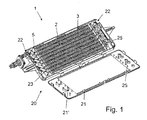
- the PTC elements 3 in one serving as a heater PTC heating arrangement 1 of a motor vehicle air conditioning system with a plurality of electrical heating element 2 in the form of a heating grid forming PTC elements 3, the PTC elements 3 in a known manner between two contact plates 4, 4 'glued, in this case by means a two-component silicone adhesive, wherein one of the contact plates, provided in the drawing by the reference numeral 4 ', is substantially rectangular in shape and forms with its laterally beyond the PTC element 3 projecting end part of an electrical contact 5.
- the designated by the reference numeral 4 contact plate is substantially rectangular in shape and arranged parallel to the other contact plate 4 '.
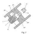
- the extended contact plate 4 'with an intermediate element 7 is firmly connected or optionally formed integrally, which is slightly narrower and at an angle of 45 ° to the contact plate 4 'extending tongue 8, on which an electrically contacting a contact sleeve 10 is pushed, which is electrically contacting firmly connected to a round cable 11 on the other side.
- the central longitudinal axis of the intermediate element 7 and the round cable 11 in the region clamped in the king pin 10 are in the present case aligned with one another (cf., FIG. 4).
- the contact sleeve 10 is a metallic stamped and bent part and has three areas 10 ', 10 "and 10"', wherein the first area 10 'is pushed over the tongue 8 and in the elastically deformable areas of at least one flat side of the tongue. 8 spring-loaded under bias. Furthermore, end stops for the tongue 8 are provided between the first area 10 'and the middle, second area 10 "(see Fig. 7) . The middle, second area 10" (see Fig. 8) forms the transition to the third area 10 "', in which the contact sleeve 10 is pushed over the round cable 11.
- a two-part plastic housing 20 is arranged, which is arranged in an air duct of the motor vehicle air conditioner.
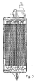
- the housing 20 is not divided in the middle, but, as shown for example in FIG. 1, the housing lower part 20 'forms the largest part of the housing 20, and the housing upper part 20 "is designed substantially as a lid, wherein the edges of the lid slightly behind This configuration of the housing parts 20 'and 20 "helps to avoid assembly errors.
- the housing 20 is embodied substantially mirror-symmetrically with respect to the central transverse axis, although in this case the electrical contacting takes place only on one side.
- the electrical contact can be provided accordingly also on the other side, so that a housing 20 can be used for various applications.
- the arrangement in the motor vehicle is present in the area below the front row of seats, so that the heating assembly 1, the air supplied to the second row of seats heated as needed.
- the two parts of the housing 20 are connected by means of clip connections 21 with the insert of the heating element 2 firmly together.
- the clip connections 21 additionally allow positioning during assembly.
- open cable bushings 22 are provided in the region of the corners in the longitudinal direction, wherein in the present case only one of the two mirror-symmetrical cable bushings 22 is used for a cable feedthrough (see Fig .. 1).
- positioning elements 23 are formed, which allow exact positioning of the corresponding areas and securely fix them in the assembled state of the housing 20.
- Protruding webs 24 'on the housing lower part 20' serve as positioning elements 23.
- the webs 24 'on the housing lower part 20' are designed in accordance with the course of the intermediate elements 7, ie angled at a 45 ° angle (see FIG Positioning between the lower housing part 20 'and the upper housing part 20 "further webs 24' on the housing lower part 20 'and webs 24" on the housing upper part 20 "are provided which are arranged substantially in the assembly direction aligned with each other and symmetrical to the central longitudinal axis of the contact sleeve 10 (see FIG. 7).
- clip connections 21 ' are also provided in the region between the electrical contacting of the contact plates 4' and the electrical contacting of the round cables 11, wherein four spring arms on the upper housing part 20 "and four undercuts cooperating with the lower housing part 20 'are formed in the present case.
- partitions 25 are formed, which hold the two arranged on the two sides of a PTC element 3 contact plates 4 and 4' or 4 spaced from each other and ensure that no short circuit occurs between them the partitions 25 extend in the housing lower part 20 "rib-like in the assembly direction, while the partitions 25 are formed in the upper housing part 20 'as protruding projections in the assembly direction.
- the electrical heating element 2 is positioned together with its electrical contact including the round cable 11 in the housing base 20 ', then the housing upper part 20 "is placed and fixed by means of the clip connections 21 and 21' on the housing base 20 ', so that the heating element 2 including the electrical contact of the same is securely and well fixed in the interior of the housing 20 is included.
Claims (18)
- Ensemble de chauffage électrique pour un véhicule automobile, avec un boîtier (20) au moins en deux parties à travers lequel circule si nécessaire de l'air à réchauffer, et au moins un élément de chauffe (2) pouvant être actionné électriquement par un contact électrique, l'élément de chauffe étant disposé dans le boîtier (20), caractérisé en ce qu'à au moins deux emplacements du boîtier (20) sont prévus des éléments de positionnement pour le contact électrique, le contact électrique étant disposé toutefois à un seul des emplacements.
- Ensemble de chauffage électrique selon la revendication 1, caractérisé en ce que le boîtier (20) est configuré symétrique par rapport à un axe transversal central, et les emplacements avec les éléments de positionnement pour un contact électrique sont disposés à distance de l'axe transversal central des deux côtés du boîtier (20).
- Ensemble de chauffage électrique selon la revendication 1 ou 2, caractérisé en ce que le contact électrique de l'élément de chauffe (2) avec un câble (11) est disposé dans le boîtier (20).
- Ensemble de chauffage électrique selon l'une quelconque des revendications précédentes, caractérisé en ce que deux parties (20', 20") du boîtier (20) sont reliées l'une à l'autre au moyen d'au moins une liaison par encliquetage (21').
- Ensemble de chauffage électrique selon l'une quelconque des revendications précédentes, caractérisé en ce que la liaison par encliquetage (21') est disposée sur le côté de l'élément de chauffe électrique (2) dans la zone de son contact électrique.
- Ensemble de chauffage électrique selon l'une quelconque des revendications précédentes, caractérisé en ce que des brides (24', 24") prévues dans la zone du contact électrique sont intégrées dans le boîtier (20), lesquelles fixent les éléments entrant en contact électrique et évitent un détachement du contact électrique.
- Ensemble de chauffage électrique selon la revendication 6, caractérisé en ce que les brides (24', 24") sont disposées à un angle variable de 0° et 90° par rapport au sens longitudinal des tôles de contact.
- Ensemble de chauffage électrique selon la revendication 6 ou 7, caractérisé en ce que l'angle est de 45°+/-20°, en particulier d'environ 45°.
- Ensemble de chauffage électrique selon l'une quelconque des revendications 6 à 8, caractérisé en ce que les brides (24', 24") sont disposées en biais et décalées par rapport à un passage de câbles pour le câble électrique.
- Ensemble de chauffage électrique selon l'une quelconque des revendications précédentes, caractérisé en ce que le contact électrique entre la tôle de contact (4') et le câble électrique (11) a lieu au moyen d'une douille de contact (10) et éventuellement au moyen d'un élément intermédiaire (7) qui est disposé entre la tôle de contact (4') et la douille de contact (10) et prolonge la tôle de contact (4').
- Ensemble de chauffage électrique selon l'une quelconque des revendications précédentes, caractérisé en ce que l'élément de chauffe électrique (2) comprend au moins un élément à coefficient de température positive (3).
- Ensemble de chauffage électrique selon la revendication 11, caractérisé en ce que des tôles de contact (4, 4') sont disposées des deux côtés de l'élément à coefficient de température positive (3).
- Ensemble de chauffage électrique selon la revendication 12, caractérisé en ce qu'au moins deux tôles de contact (4') sont formées de sorte qu'elles sont configurées à une de leur extrémité comme une partie d'une fiche (5).
- Ensemble de chauffage électrique selon l'une quelconque des revendications précédentes, caractérisé en ce que le boîtier (20) comprend au moins une cloison isolante (25) qui garantit l'absence d'un court-circuit à l'intérieur de l'élément de chauffe électrique (2).
- Ensemble de chauffage électrique selon la revendication 14, caractérisé en ce que la cloison (25) est configurée sur la partie supérieure de boîtier (20") et sur la partie inférieure de boîtier (20').
- Ensemble de chauffage électrique selon la revendication 14 ou 15, caractérisé en ce que la cloison (25) entre deux tôles de contact (4, 4') dépasse dans le prolongement d'un élément à coefficient de température positive (3) disposé entre les deux tôles.
- Ensemble de chauffage électrique selon l'une quelconque des revendications précédentes, caractérisé en ce que le boîtier (20) est conçu en deux parties comme un boîtier en plastique (20) dans la zone dans laquelle se trouve l'élément de chauffe électrique (2).
- Installation de chauffage et/ou de climatisation de véhicule automobile avec un ensemble de chauffage électrique selon l'une quelconque des revendications précédentes, caractérisée en ce que l'installation de chauffage et/ou de climatisation de véhicule automobile comprend au moins un des composants suivants : échangeur thermique, corps de chauffe, évaporateur, filtre, volet de mélangeur thermique, chambre de répartition d'air, un ou plusieurs canaux hydrauliques et un ou plusieurs volets de commande pour répartir l'air sur les canaux de sortie.
Priority Applications (3)
| Application Number | Priority Date | Filing Date | Title |
|---|---|---|---|
| AT04292584T ATE380695T1 (de) | 2004-10-29 | 2004-10-29 | Elektrische heizungsanordnung, inbesondere für ein kraftfahrzeug |
| EP04292584A EP1652704B1 (fr) | 2004-10-29 | 2004-10-29 | Ensemble de chauffage électrique, notamment pour véhicule automobile |
| DE502004005712T DE502004005712D1 (de) | 2004-10-29 | 2004-10-29 | Elektrische Heizungsanordnung, inbesondere für ein Kraftfahrzeug |
Applications Claiming Priority (1)
| Application Number | Priority Date | Filing Date | Title |
|---|---|---|---|
| EP04292584A EP1652704B1 (fr) | 2004-10-29 | 2004-10-29 | Ensemble de chauffage électrique, notamment pour véhicule automobile |
Publications (2)
| Publication Number | Publication Date |
|---|---|
| EP1652704A1 EP1652704A1 (fr) | 2006-05-03 |
| EP1652704B1 true EP1652704B1 (fr) | 2007-12-12 |
Family
ID=34931494
Family Applications (1)
| Application Number | Title | Priority Date | Filing Date |
|---|---|---|---|
| EP04292584A Not-in-force EP1652704B1 (fr) | 2004-10-29 | 2004-10-29 | Ensemble de chauffage électrique, notamment pour véhicule automobile |
Country Status (3)
| Country | Link |
|---|---|
| EP (1) | EP1652704B1 (fr) |
| AT (1) | ATE380695T1 (fr) |
| DE (1) | DE502004005712D1 (fr) |
Families Citing this family (2)
| Publication number | Priority date | Publication date | Assignee | Title |
|---|---|---|---|---|
| EP2017547B1 (fr) | 2007-07-18 | 2013-10-02 | Eberspächer catem GmbH & Co. KG | Dispositif de chauffage électrique |
| DE102008050481A1 (de) * | 2008-07-21 | 2010-01-28 | Beru Ag | Fahrzeugheizung, Fahrzeugklimaanlage mit Heizvorrichtung und Verfahren zur Montage einer Heizvorrichtung |
Family Cites Families (6)
| Publication number | Priority date | Publication date | Assignee | Title |
|---|---|---|---|---|
| DE10144757B4 (de) | 2001-09-11 | 2006-03-30 | Webasto Ag | Zusatzheizung für Personenfahrzeuge |
| FR2742384B1 (fr) * | 1995-12-19 | 1998-01-30 | Valeo Climatisation | Dispositif de chauffage-ventilation de l'habitacle d'un vehicule automobile |
| FR2762958B1 (fr) * | 1997-05-02 | 1999-08-13 | Realisations Et Diffusion Pour | Dispositif de chauffage a elements resistifs a coefficient de temperature positif |
| DE19738318C5 (de) * | 1997-09-02 | 2014-10-30 | Behr Gmbh & Co. Kg | Elektrische Heizeinrichtung für ein Kraftfahrzeug |
| DE10241763A1 (de) * | 2002-09-10 | 2004-03-18 | Horst Knappe | Heizplatte |
| DE20218331U1 (de) * | 2002-11-25 | 2004-04-01 | Alloc A/S | Beheiztes Bodenpaneel |
-
2004
- 2004-10-29 EP EP04292584A patent/EP1652704B1/fr not_active Not-in-force
- 2004-10-29 DE DE502004005712T patent/DE502004005712D1/de active Active
- 2004-10-29 AT AT04292584T patent/ATE380695T1/de not_active IP Right Cessation
Also Published As
| Publication number | Publication date |
|---|---|
| DE502004005712D1 (de) | 2008-01-24 |
| EP1652704A1 (fr) | 2006-05-03 |
| ATE380695T1 (de) | 2007-12-15 |
Similar Documents
| Publication | Publication Date | Title |
|---|---|---|
| EP2017548B1 (fr) | Dispositif de chauffage électrique, en particulier pour véhicules automobiles | |
| EP3079442B1 (fr) | Dispositif de chauffage électrique et cadre associé | |
| EP0175121A1 (fr) | Tableau d'instruments pour véhicules | |
| EP1523226B1 (fr) | Ensemble de chauffage comprenant des éléments PTC, particulièrement pour véhicules à moteurs | |
| DE112016000688T5 (de) | Elektrische Heizvorrichtung | |
| DE102013000628B4 (de) | Halterahmen einer Frischluftklappe eines Kraftfahrzeuges sowie Frischluftklappe mit Halterahmen | |
| EP1621378B2 (fr) | Dispositif de chauffage comprenant un élément chauffant, en particulier pour un véhicule | |
| DE4420673B4 (de) | Verbinderbefestigungsanordnung | |
| EP2407327B1 (fr) | Dispositif de chauffage électrique, notamment chauffage auxiliaire de véhicule automobile et climatisation de véhicule automobile | |
| DE102014205744A1 (de) | Steuergerät für ein Fahrzeugheizgerät | |
| WO2017080635A1 (fr) | Système de fixation | |
| EP1652704B1 (fr) | Ensemble de chauffage électrique, notamment pour véhicule automobile | |
| EP1715175A2 (fr) | Dispositif de chauffage pour un élément gazeux ou un élément liquide à chauffer | |
| WO2005037584A1 (fr) | Dispositif de chauffage pourvu d'un element ptc, conçu en particulier pour un vehicule automobile | |
| EP1691579A1 (fr) | Dispositif de chauffage électrique, en particulier pour véhicule à moteur | |
| EP1652703B1 (fr) | Chauffage éléctrique pour véhicule | |
| EP1486363B1 (fr) | Dispositif de chauffage comprenant un élément ptc, en particulier pour véhicule | |
| DE3210019A1 (de) | Gehaeuse fuer eine heizungs- oder klimaanlage fuer kraftfahrzeuge | |
| DE10065203A1 (de) | Einrichtung zum Steuern von Luftströmen in einer Heiz- oder Klimaanlage eines Kraftfahrzeuges | |
| EP1621826B1 (fr) | Ensemble de chauffage avec un élément CTP, notamment pour un véhicule automobile | |
| EP1769970B1 (fr) | Système de fixation | |
| DE102010046315A1 (de) | Klimaanlage für Kraftfahrzeuge | |
| EP2867961B1 (fr) | Système de canal | |
| DE112016000677T5 (de) | Elektrische Heizvorrichtung und Luftumlaufleitung in einer Lüftungs-, Heizungs- und/oder Klimatisierungsanlage | |
| EP3615365A1 (fr) | Ensemble accumulateur |
Legal Events
| Date | Code | Title | Description |
|---|---|---|---|
| PUAI | Public reference made under article 153(3) epc to a published international application that has entered the european phase |
Free format text: ORIGINAL CODE: 0009012 |
|
| AK | Designated contracting states |
Kind code of ref document: A1 Designated state(s): AT BE BG CH CY CZ DE DK EE ES FI FR GB GR HU IE IT LI LU MC NL PL PT RO SE SI SK TR |
|
| AX | Request for extension of the european patent |
Extension state: AL HR LT LV MK |
|
| 17P | Request for examination filed |
Effective date: 20061103 |
|
| AKX | Designation fees paid |
Designated state(s): AT BE BG CH CY CZ DE DK EE ES FI FR GB GR HU IE IT LI LU MC NL PL PT RO SE SI SK TR |
|
| GRAP | Despatch of communication of intention to grant a patent |
Free format text: ORIGINAL CODE: EPIDOSNIGR1 |
|
| GRAS | Grant fee paid |
Free format text: ORIGINAL CODE: EPIDOSNIGR3 |
|
| GRAA | (expected) grant |
Free format text: ORIGINAL CODE: 0009210 |
|
| AK | Designated contracting states |
Kind code of ref document: B1 Designated state(s): AT BE BG CH CY CZ DE DK EE ES FI FR GB GR HU IE IT LI LU MC NL PL PT RO SE SI SK TR |
|
| REG | Reference to a national code |
Ref country code: GB Ref legal event code: FG4D Free format text: NOT ENGLISH |
|
| REG | Reference to a national code |
Ref country code: CH Ref legal event code: EP |
|
| REG | Reference to a national code |
Ref country code: IE Ref legal event code: FG4D Free format text: LANGUAGE OF EP DOCUMENT: GERMAN |
|
| REF | Corresponds to: |
Ref document number: 502004005712 Country of ref document: DE Date of ref document: 20080124 Kind code of ref document: P |
|
| REG | Reference to a national code |
Ref country code: SE Ref legal event code: TRGR |
|
| PG25 | Lapsed in a contracting state [announced via postgrant information from national office to epo] |
Ref country code: SI Free format text: LAPSE BECAUSE OF FAILURE TO SUBMIT A TRANSLATION OF THE DESCRIPTION OR TO PAY THE FEE WITHIN THE PRESCRIBED TIME-LIMIT Effective date: 20071212 Ref country code: FI Free format text: LAPSE BECAUSE OF FAILURE TO SUBMIT A TRANSLATION OF THE DESCRIPTION OR TO PAY THE FEE WITHIN THE PRESCRIBED TIME-LIMIT Effective date: 20071212 Ref country code: PL Free format text: LAPSE BECAUSE OF FAILURE TO SUBMIT A TRANSLATION OF THE DESCRIPTION OR TO PAY THE FEE WITHIN THE PRESCRIBED TIME-LIMIT Effective date: 20071212 Ref country code: NL Free format text: LAPSE BECAUSE OF FAILURE TO SUBMIT A TRANSLATION OF THE DESCRIPTION OR TO PAY THE FEE WITHIN THE PRESCRIBED TIME-LIMIT Effective date: 20071212 |
|
| NLV1 | Nl: lapsed or annulled due to failure to fulfill the requirements of art. 29p and 29m of the patents act | ||
| GBV | Gb: ep patent (uk) treated as always having been void in accordance with gb section 77(7)/1977 [no translation filed] | ||
| PG25 | Lapsed in a contracting state [announced via postgrant information from national office to epo] |
Ref country code: ES Free format text: LAPSE BECAUSE OF FAILURE TO SUBMIT A TRANSLATION OF THE DESCRIPTION OR TO PAY THE FEE WITHIN THE PRESCRIBED TIME-LIMIT Effective date: 20080323 |
|
| ET | Fr: translation filed | ||
| PG25 | Lapsed in a contracting state [announced via postgrant information from national office to epo] |
Ref country code: RO Free format text: LAPSE BECAUSE OF FAILURE TO SUBMIT A TRANSLATION OF THE DESCRIPTION OR TO PAY THE FEE WITHIN THE PRESCRIBED TIME-LIMIT Effective date: 20071212 Ref country code: SK Free format text: LAPSE BECAUSE OF FAILURE TO SUBMIT A TRANSLATION OF THE DESCRIPTION OR TO PAY THE FEE WITHIN THE PRESCRIBED TIME-LIMIT Effective date: 20071212 |
|
| PG25 | Lapsed in a contracting state [announced via postgrant information from national office to epo] |
Ref country code: PT Free format text: LAPSE BECAUSE OF FAILURE TO SUBMIT A TRANSLATION OF THE DESCRIPTION OR TO PAY THE FEE WITHIN THE PRESCRIBED TIME-LIMIT Effective date: 20080512 |
|
| REG | Reference to a national code |
Ref country code: IE Ref legal event code: FD4D |
|
| PLBE | No opposition filed within time limit |
Free format text: ORIGINAL CODE: 0009261 |
|
| STAA | Information on the status of an ep patent application or granted ep patent |
Free format text: STATUS: NO OPPOSITION FILED WITHIN TIME LIMIT |
|
| PG25 | Lapsed in a contracting state [announced via postgrant information from national office to epo] |
Ref country code: IE Free format text: LAPSE BECAUSE OF FAILURE TO SUBMIT A TRANSLATION OF THE DESCRIPTION OR TO PAY THE FEE WITHIN THE PRESCRIBED TIME-LIMIT Effective date: 20071212 Ref country code: DK Free format text: LAPSE BECAUSE OF FAILURE TO SUBMIT A TRANSLATION OF THE DESCRIPTION OR TO PAY THE FEE WITHIN THE PRESCRIBED TIME-LIMIT Effective date: 20071212 |
|
| 26N | No opposition filed |
Effective date: 20080915 |
|
| PG25 | Lapsed in a contracting state [announced via postgrant information from national office to epo] |
Ref country code: GB Free format text: LAPSE BECAUSE OF FAILURE TO SUBMIT A TRANSLATION OF THE DESCRIPTION OR TO PAY THE FEE WITHIN THE PRESCRIBED TIME-LIMIT Effective date: 20071212 |
|
| PG25 | Lapsed in a contracting state [announced via postgrant information from national office to epo] |
Ref country code: GR Free format text: LAPSE BECAUSE OF FAILURE TO SUBMIT A TRANSLATION OF THE DESCRIPTION OR TO PAY THE FEE WITHIN THE PRESCRIBED TIME-LIMIT Effective date: 20080313 |
|
| BERE | Be: lapsed |
Owner name: BEHR FRANCE ROUFFACH SAS Effective date: 20081031 |
|
| PG25 | Lapsed in a contracting state [announced via postgrant information from national office to epo] |
Ref country code: EE Free format text: LAPSE BECAUSE OF FAILURE TO SUBMIT A TRANSLATION OF THE DESCRIPTION OR TO PAY THE FEE WITHIN THE PRESCRIBED TIME-LIMIT Effective date: 20071212 Ref country code: BG Free format text: LAPSE BECAUSE OF FAILURE TO SUBMIT A TRANSLATION OF THE DESCRIPTION OR TO PAY THE FEE WITHIN THE PRESCRIBED TIME-LIMIT Effective date: 20080312 |
|
| PG25 | Lapsed in a contracting state [announced via postgrant information from national office to epo] |
Ref country code: MC Free format text: LAPSE BECAUSE OF NON-PAYMENT OF DUE FEES Effective date: 20081031 |
|
| REG | Reference to a national code |
Ref country code: CH Ref legal event code: PL |
|
| PG25 | Lapsed in a contracting state [announced via postgrant information from national office to epo] |
Ref country code: CY Free format text: LAPSE BECAUSE OF FAILURE TO SUBMIT A TRANSLATION OF THE DESCRIPTION OR TO PAY THE FEE WITHIN THE PRESCRIBED TIME-LIMIT Effective date: 20071212 |
|
| PG25 | Lapsed in a contracting state [announced via postgrant information from national office to epo] |
Ref country code: BE Free format text: LAPSE BECAUSE OF NON-PAYMENT OF DUE FEES Effective date: 20081031 |
|
| PG25 | Lapsed in a contracting state [announced via postgrant information from national office to epo] |
Ref country code: LI Free format text: LAPSE BECAUSE OF NON-PAYMENT OF DUE FEES Effective date: 20081031 Ref country code: CH Free format text: LAPSE BECAUSE OF NON-PAYMENT OF DUE FEES Effective date: 20081031 |
|
| PG25 | Lapsed in a contracting state [announced via postgrant information from national office to epo] |
Ref country code: AT Free format text: LAPSE BECAUSE OF NON-PAYMENT OF DUE FEES Effective date: 20081029 |
|
| PGFP | Annual fee paid to national office [announced via postgrant information from national office to epo] |
Ref country code: IT Payment date: 20091028 Year of fee payment: 6 |
|
| PG25 | Lapsed in a contracting state [announced via postgrant information from national office to epo] |
Ref country code: LU Free format text: LAPSE BECAUSE OF NON-PAYMENT OF DUE FEES Effective date: 20081029 Ref country code: HU Free format text: LAPSE BECAUSE OF FAILURE TO SUBMIT A TRANSLATION OF THE DESCRIPTION OR TO PAY THE FEE WITHIN THE PRESCRIBED TIME-LIMIT Effective date: 20080613 |
|
| PG25 | Lapsed in a contracting state [announced via postgrant information from national office to epo] |
Ref country code: TR Free format text: LAPSE BECAUSE OF FAILURE TO SUBMIT A TRANSLATION OF THE DESCRIPTION OR TO PAY THE FEE WITHIN THE PRESCRIBED TIME-LIMIT Effective date: 20071212 |
|
| PGFP | Annual fee paid to national office [announced via postgrant information from national office to epo] |
Ref country code: CZ Payment date: 20100927 Year of fee payment: 7 |
|
| PGFP | Annual fee paid to national office [announced via postgrant information from national office to epo] |
Ref country code: SE Payment date: 20101020 Year of fee payment: 7 |
|
| PG25 | Lapsed in a contracting state [announced via postgrant information from national office to epo] |
Ref country code: IT Free format text: LAPSE BECAUSE OF NON-PAYMENT OF DUE FEES Effective date: 20101029 |
|
| REG | Reference to a national code |
Ref country code: SE Ref legal event code: EUG |
|
| PG25 | Lapsed in a contracting state [announced via postgrant information from national office to epo] |
Ref country code: CZ Free format text: LAPSE BECAUSE OF NON-PAYMENT OF DUE FEES Effective date: 20111029 |
|
| PG25 | Lapsed in a contracting state [announced via postgrant information from national office to epo] |
Ref country code: SE Free format text: LAPSE BECAUSE OF NON-PAYMENT OF DUE FEES Effective date: 20111030 |
|
| REG | Reference to a national code |
Ref country code: DE Ref legal event code: R082 Ref document number: 502004005712 Country of ref document: DE Representative=s name: GRAUEL, ANDREAS, DIPL.-PHYS. DR. RER. NAT., DE Ref country code: DE Ref legal event code: R081 Ref document number: 502004005712 Country of ref document: DE Owner name: MAHLE INTERNATIONAL GMBH, DE Free format text: FORMER OWNER: BEHR FRANCE ROUFFACH S.A.S., ROUFFACH, FR |
|
| REG | Reference to a national code |
Ref country code: FR Ref legal event code: PLFP Year of fee payment: 12 |
|
| REG | Reference to a national code |
Ref country code: FR Ref legal event code: PLFP Year of fee payment: 13 |
|
| REG | Reference to a national code |
Ref country code: FR Ref legal event code: PLFP Year of fee payment: 14 |
|
| REG | Reference to a national code |
Ref country code: FR Ref legal event code: PLFP Year of fee payment: 15 |
|
| PGFP | Annual fee paid to national office [announced via postgrant information from national office to epo] |
Ref country code: DE Payment date: 20181030 Year of fee payment: 15 |
|
| PGFP | Annual fee paid to national office [announced via postgrant information from national office to epo] |
Ref country code: FR Payment date: 20181026 Year of fee payment: 15 |
|
| REG | Reference to a national code |
Ref country code: DE Ref legal event code: R119 Ref document number: 502004005712 Country of ref document: DE |
|
| PG25 | Lapsed in a contracting state [announced via postgrant information from national office to epo] |
Ref country code: DE Free format text: LAPSE BECAUSE OF NON-PAYMENT OF DUE FEES Effective date: 20200501 |
|
| PG25 | Lapsed in a contracting state [announced via postgrant information from national office to epo] |
Ref country code: FR Free format text: LAPSE BECAUSE OF NON-PAYMENT OF DUE FEES Effective date: 20191031 |