EP1652560A1 - Setting means for a front jaw of a ski binding or the like - Google Patents
Setting means for a front jaw of a ski binding or the like Download PDFInfo
- Publication number
- EP1652560A1 EP1652560A1 EP05022777A EP05022777A EP1652560A1 EP 1652560 A1 EP1652560 A1 EP 1652560A1 EP 05022777 A EP05022777 A EP 05022777A EP 05022777 A EP05022777 A EP 05022777A EP 1652560 A1 EP1652560 A1 EP 1652560A1
- Authority
- EP
- European Patent Office
- Prior art keywords
- base
- bar
- handle
- accessory
- gliding board
- Prior art date
- Legal status (The legal status is an assumption and is not a legal conclusion. Google has not performed a legal analysis and makes no representation as to the accuracy of the status listed.)
- Granted
Links
- 230000000295 complement effect Effects 0.000 claims description 5
- 238000006073 displacement reaction Methods 0.000 claims description 3
- 230000000694 effects Effects 0.000 description 3
- 230000001629 suppression Effects 0.000 description 2
- 230000000903 blocking effect Effects 0.000 description 1
- 230000001939 inductive effect Effects 0.000 description 1
- 238000004519 manufacturing process Methods 0.000 description 1
- 230000001737 promoting effect Effects 0.000 description 1
- 230000001869 rapid Effects 0.000 description 1
- 230000007704 transition Effects 0.000 description 1
Images

Classifications
-
- A—HUMAN NECESSITIES
- A63—SPORTS; GAMES; AMUSEMENTS
- A63C—SKATES; SKIS; ROLLER SKATES; DESIGN OR LAYOUT OF COURTS, RINKS OR THE LIKE
- A63C9/00—Ski bindings
- A63C9/005—Ski bindings with means for adjusting the position of a shoe holder or of the complete binding relative to the ski
Definitions
- the invention relates to an adjustable attachment device of an accessory on a gliding board, particularly adapted to the attachment to a ski of a stop before a ski boot fastening device, allowing its longitudinal adjustment.
- a general object of the present invention is to provide an adjustable attachment device of an accessory on a gliding board that does not have the above disadvantages.
- a first object of the invention is to provide an adjustable attachment device of an accessory on a gliding board, user friendly and easy to use in all conditions.
- a second object of the invention is to provide an adjustable attachment device of an accessory on a gliding board for fixing without play.
- a third object of the invention is to provide an adjustable attachment device of an accessory on a gliding board for secure attachment.
- a fourth object of the invention is to provide an adjustable attachment device of an accessory on a gliding board, simple and easy to assemble.
- a fifth object of the invention is to provide an adjustable and aesthetic attachment device of an accessory on a gliding board.
- the invention is based on an adjustable attachment device of an accessory on a gliding board comprising a base, comprising locations for fixing the accessory and in which is housed a bar having a toothed portion adapted for positioning in a complementary toothed portion integral with the gliding board, the bar being mounted rotatably on the base about an axis, comprising on both sides of this axis the toothed portion and an end, and comprising a handle that can occupy two different positions, comprising a camming surface cooperating with the end of the bar, so that a first position of the handle corresponds to a low position of the toothed portion, and a second position corresponds to a high position of the toothed portion.
- the bar may be arranged in the longitudinal direction of the base, the toothed portion being substantially in the central portion of the base and the end of the bar and the lever being towards one end of the base.
- the handle may have a cam surface including a first portion in contact with the end of the bar when the toothed portion and the handle are in a low position and a second portion at a greater distance from the axis of rotation of the handle which causes a downward movement of the end of the bar when the lever is in its second high position, corresponding to a high position of the toothed portion.
- the device may comprise a spring mounted on the base and exerting a force on the bar tending to maintain its toothed part in low position.
- the handle may include a second cam surface of which two portions are in contact with a piston of the base so that the piston exerts downward pressure when the handle is in its down position to block play of the base.
- the base may comprise at least one location for receiving a ski binding before stop and the handle can be positioned towards the rear end of the base for receiving a ski boot.
- the invention also relates to a front ski binding stop which comprises a fixing device adjustable from its longitudinal position according to the invention.
- the invention also relates to the assembly comprising the device for attaching an accessory to a gliding board described above and to an element intended to be firmly fixed to the gliding board and comprising a toothed portion corresponding to the toothed portion of the bar.
- the invention also relates to a ski comprising an adjustable attachment device of an accessory as described above.
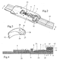
- the device comprises an elongate base 1, comprising a slot 2 in which is positioned a longitudinal bar 3.
- the location 2 consists of an opening 4 and a location 5 to respectively receive a toothed portion 6 of the bar 3 and a connection with a circular arc-shaped portion of the bar.
- This link allows the bar 3 to be rotatable about an axis 7 on the location 5 relative to the base 1, allowing the toothed portion 6 of the bar, which is in a lower plane and substantially parallel to the plane of the rest of the bar 3, to traverse the opening 4 in its lowest position to be able to be fixed in a complementary toothed part integral with the gliding board, which will be described later, or occupy a higher position within the opening 4 in which it is released from the complementary toothed portion.
- This mechanism will be described in more detail with reference to FIGS. 4 to 9.
- the base 1 further comprises a means 8 for maintaining a spring 9 which has the effect of exerting a force downwardly on the toothed portion 6 of the bar in order to push it back to its lower position. It further comprises a housing 10 in which is mounted rotatably about an axis 11 a lever 12 whose first function is to act on the end 13 of the bar to allow it to move from its low position to its raised position.
- the device comprises a locking piston 14, surrounded by two return springs 15, all three mounted in three openings 16 of the base 1.
- the assembly is surmounted by a spring plate 17 connected to the locking piston 14 and cooperating with the joystick 12.
- FIG. 2 illustrates the previously described adjustment device mounted integrally on a gliding board, via an element 19 integral with the gliding board and comprising slides 20 on which the base 1 can slide by means of slides. corresponding longitudinal 21.
- the element 19 further comprises a portion 22 comprising two lateral rows 23 of teeth. These teeth are in a plane parallel to the element 19 and oriented transversely to the slides 20, directed towards a central opening 24 located between the two rows 23 of teeth.
- the dimensions of the central opening 24 correspond to the toothed portion 6 of the bar 3, whose teeth can thus be housed between the teeth of the rows 23 in order to fix the base 1 on the element 19 by preventing a longitudinal sliding of the base 1 relative to the gliding board.
- the base 1 comprises locations 25 adapted for attachment of an accessory such as a front stop ski attachment for example.
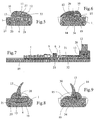
- Figure 3 shows the handle 12 which comprises an opening 26 for receiving an axis 11 and to be rotated about this axis. It has a shape particularly adapted to its manual rotation about this axis 11. It comprises a first cam surface comprising a first portion 27 and a second portion 28, intended to cooperate with the end 13 of the bar 3. It comprises of plus a second cam surface including a first portion 29 and a second portion 30 for cooperating with the spring plate 17.
- Figures 4 to 6 illustrate the device in a first position of the lever 12 which corresponds to the fixing position of the base 1.
- the lever 12 is in its lowered position on the base 1 and its surface cam 27 is in contact with the end 13 of the bar 3.
- the end 13 of the bar occupies a raised position and the spring 9 keeps the toothed portion 6 in its lower position in which it passes through the opening 4 of the base to be housed in the teeth of the rows 23 of the element 19 on the gliding board, thus preventing longitudinal movement of the base 1.
- the upper portion 31 of the bar 3 is in contact with a corresponding portion 32 of the base over a length of about one third of the total length of the bar, which ensures a precise positioning of the bar 3.
- this part has a slight slope which allows to its end 13 to have a potential freedom of movement relative to the base 1 which does not follow this slope towards its end and thus releases a space 33 between the end 13 of the bar and its housing 4 provided in the base 1.
- FIG. 6 illustrates the positioning of the second cam surface of the lever 12 in this low position in which its cam surface 29 is in contact with the plate 17 and the piston 14, pushing it back into a low position such as the base 34 of the piston bears against the element 19.
- the piston 14 also prevents relative movements between the base 1 and the element 19 and performs a function of blocking games, important to ensure a good connection between the stop and ski, necessary for precise skiing guidance.
- the bar 3 comprises wider portions 35 which are housed in locations 36 of the same size of the housing 4 of the base 1. This has the effect of preventing any relative longitudinal movement between the bar 3 and the base 1. Thus, the fixing of the bar 3 in the element 19 also fixes the base 1.
- Figures 7 to 9 illustrate the other extreme position of the lever 12, fully raised, in a configuration for the longitudinal adjustment of the base 1 on the ski.
- the cam surface 28 of the handle rests on the end 13 of the bar 3.
- This surface 28 is further from the axis of rotation 11 of the bar than the surface 27, the end 13 the bar is pushed downwards and passes through the space 33 until it comes to bear on the housing 4 of the base 1.
- This displacement causes by leverage the rotation of the bar 3 about the axis 7, which raises its parts 31 and 6 by opposing the spring pressure force 9.
- the toothed portion 6 is then sufficiently raised to completely out its teeth rows 23.
- the base 1 then becomes movable longitudinally along the rails 20, 21 with respect to the element 19.
- the shape of the cam surface 28 allows the lever 12 to maintain this position stably.
- FIG. 9 shows the contact between the second cam surface 30 of the lever 12 and the piston 14.
- This second portion 30 of the second cam surface being closer to the axis of rotation 11 than the first portion 29 of the second cam surface, the piston 14 and the plate 17 occupy a higher position, pushed upwards by the springs 15, thus releasing a slight gap between the base 34 of the piston and the element 19 so as not to hinder the longitudinal displacement of the base 1.
- the toothed portion 6 of the base 1 is substantially in the center of the base 1, which allows the base 1 to hide at best the fastening device integral with the gliding board, ie the element 19 and its toothed portion 22, which is not aesthetically attractive.
- the lever 12 is positioned towards the rear of the base 1 in the longitudinal direction, which makes it possible, in the case of an application with a front stop in the locations 25, the positioning of a ski boot over the lever 12, inducing a locking and a holding case of the joystick in its low position and preventing accidental opening.
Abstract
Description
L'invention concerne un dispositif de fixation réglable d'un accessoire sur une planche de glisse, particulièrement adapté à la fixation sur un ski d'une butée avant d'un dispositif de fixation de chaussure de ski, permettant son réglage longitudinal.The invention relates to an adjustable attachment device of an accessory on a gliding board, particularly adapted to the attachment to a ski of a stop before a ski boot fastening device, allowing its longitudinal adjustment.
Il est connu différents dispositifs permettant un réglage de la position longitudinale d'une butée avant d'un dispositif de fixation de chaussure de ski dans le but d'adapter la fixation à différentes longueurs de chaussures. Une solution courante de l'art antérieur est basée sur des rails de guidage positionnés sur le ski, incluant une partie dentée, sur laquelle se positionne une partie dentée complémentaire solidaire de la butée avant de la fixation de ski. En libérant ces parties dentées, on permet un réglage de la butée par son glissement longitudinal selon les rails de guidage. Toutefois, les solutions existantes présentent toutes des inconvénients parmi lesquels :
- elles nécessitent un outil pour libérer les parties dentées. Cet outil doit être introduit par une ouverture et maintenu en position durant le réglage. Dans ce cas, les solutions ne sont pas conviviales et peu pratiques pour des réglages rapides et dans toutes conditions, comme par exemple sur les pistes de ski où l'outil spécifique nécessaire n'est pas toujours disponible ; et/ou
- elles présentent un jeu au niveau de la liaison des deux parties dentées, même dans la configuration prévue pour la pratique du ski, ce qui diminue grandement la maîtrise du guidage du ski ; et/ou
- elles ne sont pas sûres, c'est à dire qu'elles peuvent entraîner des déréglages accidentels durant leur utilisation, ce qui est dangereux car cela peut entraîner la chute du skieur ; et/ou
- elles sont complexes, car basées soit sur un grand nombre d'éléments, soit sur des éléments complexes à fabriquer ou monter ; et/ou
- enfin, elles sont parfois peu esthétiques car des éléments mécaniques peu esthétiques sont visibles.
- they require a tool to release the toothed parts. This tool must be inserted through an opening and held in position during adjustment. In this case, the solutions are not user-friendly and impractical for quick adjustments and in all conditions, for example on ski slopes where the specific tool required is not always available; and or
- they have a play at the level of the connection of the two toothed parts, even in the configuration provided for the practice of skiing, which greatly reduces the control of the ski guide; and or
- they are not safe, that is to say that they can lead to accidental misalignment during their use, which is dangerous because it can cause the skier to fall; and or
- they are complex because they are based on a large number of elements, or on complex elements to manufacture or to mount; and or
- finally, they are sometimes unattractive because unattractive mechanical elements are visible.
Il existe aujourd'hui un besoin d'une autre solution de dispositif de réglage d'un accessoire sur une planche de glisse.There is now a need for another solution for adjusting an accessory on a gliding board.
Un objet général de la présente invention est de proposer un dispositif de fixation réglable d'un accessoire sur une planche de glisse qui ne présente pas les inconvénients précédents.A general object of the present invention is to provide an adjustable attachment device of an accessory on a gliding board that does not have the above disadvantages.
Plus précisément, un premier objet de l'invention consiste à proposer un dispositif de fixation réglable d'un accessoire sur une planche de glisse, convivial et facile à utiliser dans toutes conditions.More specifically, a first object of the invention is to provide an adjustable attachment device of an accessory on a gliding board, user friendly and easy to use in all conditions.
Un second objet de l'invention consiste à proposer un dispositif de fixation réglable d'un accessoire sur une planche de glisse permettant une fixation sans jeu.A second object of the invention is to provide an adjustable attachment device of an accessory on a gliding board for fixing without play.
Un troisième objet de l'invention consiste à proposer un dispositif de fixation réglable d'un accessoire sur une planche de glisse permettant une fixation en toute sécurité.A third object of the invention is to provide an adjustable attachment device of an accessory on a gliding board for secure attachment.
Un quatrième objet de l'invention consiste à proposer un dispositif de fixation réglable d'un accessoire sur une planche de glisse, simple et facile à monter.A fourth object of the invention is to provide an adjustable attachment device of an accessory on a gliding board, simple and easy to assemble.
Un cinquième objet de l'invention consiste à proposer un dispositif de fixation réglable et esthétique d'un accessoire sur une planche de glisse.A fifth object of the invention is to provide an adjustable and aesthetic attachment device of an accessory on a gliding board.
L'invention repose sur un dispositif de fixation réglable d'un accessoire sur une planche de glisse comprenant une embase, comprenant des emplacements pour fixer l'accessoire et dans laquelle est logée une barrette possédant une partie dentée apte à un positionnement dans une partie dentée complémentaire solidaire de la planche de glisse, la barrette étant montée mobile en rotation sur l'embase autour d'un axe, comprenant de part et d'autre de cet axe la partie dentée et une extrémité, et comprenant une manette pouvant occuper deux positions différentes, comprenant une surface de came coopérant avec l'extrémité de la barrette, de sorte qu'une première position de la manette correspond à une position basse de la partie dentée, et une seconde position correspond à une position haute de la partie dentée.The invention is based on an adjustable attachment device of an accessory on a gliding board comprising a base, comprising locations for fixing the accessory and in which is housed a bar having a toothed portion adapted for positioning in a complementary toothed portion integral with the gliding board, the bar being mounted rotatably on the base about an axis, comprising on both sides of this axis the toothed portion and an end, and comprising a handle that can occupy two different positions, comprising a camming surface cooperating with the end of the bar, so that a first position of the handle corresponds to a low position of the toothed portion, and a second position corresponds to a high position of the toothed portion.
La barrette peut être disposée dans le sens longitudinal de l'embase, la partie dentée se trouvant sensiblement dans la partie centrale de l'embase et l'extrémité de la barrette et la manette se trouvant vers une extrémité de l'embase.The bar may be arranged in the longitudinal direction of the base, the toothed portion being substantially in the central portion of the base and the end of the bar and the lever being towards one end of the base.
La manette peut posséder une surface de came comprenant une première partie en contact avec l'extrémité de la barrette lorsque la partie dentée et la manette occupent une position basse et une seconde partie à plus grande distance de l'axe de rotation de la manette qui provoque un déplacement vers le bas de l'extrémité de la barrette quand la manette est dans sa deuxième position haute, correspondant à une position haute de la partie dentée.The handle may have a cam surface including a first portion in contact with the end of the bar when the toothed portion and the handle are in a low position and a second portion at a greater distance from the axis of rotation of the handle which causes a downward movement of the end of the bar when the lever is in its second high position, corresponding to a high position of the toothed portion.
Le dispositif peut comprendre un ressort monté sur l'embase et exerçant un effort sur la barrette tendant à maintenir sa partie dentée en position basse.The device may comprise a spring mounted on the base and exerting a force on the bar tending to maintain its toothed part in low position.
La manette peut comprendre une seconde surface de came dont deux parties sont en contact avec un piston de l'embase de sorte que le piston exerce une pression vers le bas quand la manette occupe sa position basse afin de bloquer les jeux de l'embase.The handle may include a second cam surface of which two portions are in contact with a piston of the base so that the piston exerts downward pressure when the handle is in its down position to block play of the base.
L'embase peut comprendre au moins un emplacement pour recevoir une butée avant de fixation de ski et la manette peut être positionnée vers l'extrémité arrière de l'embase destinée à recevoir une chaussure de ski.The base may comprise at least one location for receiving a ski binding before stop and the handle can be positioned towards the rear end of the base for receiving a ski boot.
L'invention porte aussi sur une butée avant de fixation de ski qui comprend un dispositif de fixation réglable de sa position longitudinale selon l'invention.The invention also relates to a front ski binding stop which comprises a fixing device adjustable from its longitudinal position according to the invention.
L'invention porte aussi sur l'ensemble composé du dispositif de fixation d'un accessoire sur une planche de glisse décrit précédemment et sur un élément destiné à être solidairement fixé sur la planche de glisse et comprenant une partie dentée correspondant à la partie dentée de la barrette.The invention also relates to the assembly comprising the device for attaching an accessory to a gliding board described above and to an element intended to be firmly fixed to the gliding board and comprising a toothed portion corresponding to the toothed portion of the bar.
Enfin, l'invention porte aussi sur un ski comprenant un dispositif de fixation réglable d'un accessoire tel que décrit précédemment.Finally, the invention also relates to a ski comprising an adjustable attachment device of an accessory as described above.
Un mode d'exécution est décrit ci-après, à titre d'exemple, en référence au dessin annexé, dans lequel :
- La figure 1 représente une vue en perspective éclatée d'un mode d'exécution de l'invention ;
- la figure 2 représente une vue en perspective non éclatée du mode d'exécution de la figure 1 ;
- la figure 3 représente une vue de face en perspective de la manette d'un mode d'exécution de l'invention ;
- la figure 4 représente une vue en coupe selon l'axe 4-4 du dispositif de l'invention dans une première position ;
- la figure 5 représente une vue en coupe selon l'axe 5-5 du dispositif de l'invention dans une première position ;
- la figure 6 représente une vue en coupe selon l'axe 6-6 du dispositif de l'invention dans une première position ;
- la figure 7 représente une vue en coupe selon l'axe 4-4 du dispositif de l'invention dans une seconde position ;
- la figure 8 représente une vue en coupe selon l'axe 8-8 du dispositif de l'invention dans une seconde position ;
- la figure 9 représente une vue en coupe selon l'axe 9-9 du dispositif de l'invention dans une seconde position ;
- Figure 1 shows an exploded perspective view of an embodiment of the invention;
- FIG. 2 represents a non-exploded perspective view of the embodiment of FIG. 1;
- FIG. 3 represents a perspective front view of the joystick of an embodiment of the invention;
- Figure 4 shows a sectional view along the axis 4-4 of the device of the invention in a first position;
- Figure 5 shows a sectional view along the axis 5-5 of the device of the invention in a first position;
- Figure 6 shows a sectional view along the axis 6-6 of the device of the invention in a first position;
- Figure 7 shows a sectional view along the axis 4-4 of the device of the invention in a second position;
- Figure 8 shows a sectional view along the axis 8-8 of the device of the invention in a second position;
- Figure 9 shows a sectional view along the axis 9-9 of the device of the invention in a second position;
Dans les différentes figures, les mêmes références seront utilisées pour les éléments correspondants.In the different figures, the same references will be used for the corresponding elements.
Comme illustré sur la figure 1, le dispositif selon un mode d'exécution de l'invention comprend une embase 1 allongée, comprenant un emplacement 2 dans lequel se positionne une barrette 3 longitudinale. L'emplacement 2 se compose d'une ouverture 4 et d'un emplacement 5 pour recevoir respectivement une partie dentée 6 de la barrette 3 et une liaison avec une partie en forme d'arc de cercle de la barrette. Cette liaison permet à la barrette 3 d'être mobile en rotation autour d'un axe 7 sur l'emplacement 5 par rapport à l'embase 1, permettant à la partie dentée 6 de la barrette, qui se trouve dans un plan inférieur et sensiblement parallèle au plan du reste de la barrette 3, de traverser l'ouverture 4 dans sa position la plus basse pour pouvoir se fixer dans une partie dentée complémentaire solidaire de la planche de glisse, qui sera décrite plus loin, ou d'occuper une position plus haute au sein de l'ouverture 4 dans laquelle elle est libérée de la partie dentée complémentaire. Ce mécanisme sera décrit plus en détail en référence avec les figures 4 à 9.As illustrated in Figure 1, the device according to one embodiment of the invention comprises an
L'embase 1 comprend de plus un moyen 8 de maintien d'un ressort 9 qui a pour effet d'exercer une force vers le bas sur la partie dentée 6 de la barrette afin de la repousser vers sa position basse. Elle comprend de plus un logement 10 dans lequel est montée mobile en rotation autour d'un axe 11 une manette 12 dont la première fonction est d'agir sur l'extrémité 13 de la barrette afin de lui permettre de passer de sa position basse à sa position relevée.The
Enfin, le dispositif comprend un piston de blocage 14, entouré de deux ressorts de rappel 15, tous trois montés dans trois ouvertures 16 de l'embase 1. L'ensemble est surmonté par une plaquette ressort 17 reliée au piston de blocage 14 et coopèrant avec la manette 12.Finally, the device comprises a
La figure 2 illustre le dispositif de réglage décrit précédemment monté solidairement sur une planche de glisse, par l'intermédiaire d'un élément 19 solidaire de la planche de glisse et comprenant des glissières 20 sur lesquelles peut coulisser l'embase 1 grâce à des glissières longitudinales correspondantes 21. L'élément 19 comprend en outre une partie 22 comprenant deux rangées latérales 23 de dents. Ces dents sont dans un plan parallèle à l'élément 19 et orientées transversalement aux glissières 20, dirigées vers une ouverture centrale 24 se trouvant entre les deux rangées 23 de dents. Les dimensions de l'ouverture centrale 24 correspondent à la partie dentée 6 de la barrette 3, dont les dents peuvent ainsi se loger entre les dents des rangées 23 afin de fixer l'embase 1 sur l'élément 19 en empêchant un glissement longitudinal de l'embase 1 par rapport à la planche de glisse. L'embase 1 comprend des emplacements 25 adaptés pour la fixation d'un accessoire comme une butée avant de fixation de ski par exemple.FIG. 2 illustrates the previously described adjustment device mounted integrally on a gliding board, via an
La figure 3 représente la manette 12 qui comprend une ouverture 26 pour recevoir un axe 11 et se monter en rotation autour de cet axe. Elle a une forme particulièrement adaptée à sa rotation manuelle autour de cet axe 11. Elle comprend une première surface de came comprenant une première partie 27 et une seconde partie 28, destinées à coopérer avec l'extrémité 13 de la barrette 3. Elle comprend de plus une seconde surface de came comprenant une première partie 29 et une seconde partie 30, destinées à coopérer avec la plaquette ressorts 17.Figure 3 shows the
Les figures 4 à 6 illustrent le dispositif dans une première position de la manette 12 qui correspond à la position de fixation de l'embase 1. Dans cette configuration, la manette 12 est dans sa position basse rabattue sur l'embase 1 et sa surface de came 27 est en contact avec l'extrémité 13 de la barrette 3. Dans cette position, l'extrémité 13 de la barrette occupe une position relevée et le ressort 9 maintient la partie dentée 6 dans sa position basse dans laquelle elle traverse l'ouverture 4 de l'embase pour venir se loger dans les dents des rangées 23 de l'élément 19 sur la planche de glisse, empêchant ainsi tout mouvement longitudinal de l'embase 1. Dans cette position stable, la partie haute 31 de la barrette 3 est en contact avec une partie correspondante 32 de l'embase sur une longueur d'environ le tiers de la longueur totale de la barrette, ce qui garantit un positionnement précis de la barrette 3. De plus, cette partie présente une légère pente qui permet à son extrémité 13 d'avoir une liberté potentielle de mouvement par rapport à l'embase 1 qui ne suit pas cette pente vers son extrémité et libère ainsi un espace 33 entre l'extrémité 13 de la barrette et son logement 4 prévu dans l'embase 1.Figures 4 to 6 illustrate the device in a first position of the
La figure 6 illustre le positionnement de la seconde surface de came de la manette 12 dans cette position basse dans laquelle sa surface de came 29 est en contact avec la plaquette 17 et le piston 14, le repoussant dans une position basse telle que la base 34 du piston vient en appui contre l'élément 19. Dans cette position, le piston 14 empêche aussi les mouvements relatifs entre l'embase 1 et l'élément 19 et remplit une fonction de blocage des jeux, importante pour assurer une bonne liaison entre la butée et le ski, nécessaire pour un guidage précis du ski.FIG. 6 illustrates the positioning of the second cam surface of the
La barrette 3 comprend des parties plus larges 35 qui se logent dans des emplacements 36 de même dimension du logement 4 de l'embase 1. Cela a pour effet d'empêcher tout mouvement longitudinal relatif entre la barrette 3 et l'embase 1. Ainsi, la fixation de la barrette 3 dans l'élément 19 fixe aussi l'embase 1.The
Les figures 7 à 9 illustrent l'autre position extrême de la manette 12, totalement relevée, dans une configuration permettant le réglage longitudinal de l'embase 1 sur le ski. Dans cette position, la surface de came 28 de la manette vient en appui sur l'extrémité 13 de la barrette 3. Cette surface 28 étant plus éloignée de l'axe de rotation 11 de la barrette que la surface 27, l'extrémité 13 de la barrette est repoussée vers le bas et traverse l'espace 33 jusqu'à venir en appui sur le logement 4 de l'embase 1. Ce déplacement provoque par effet de levier la rotation de la barrette 3 autour de l'axe 7, ce qui relève ses parties 31 et 6 en s'opposant à la force de pression du ressort 9. Comme cela est visible sur la figure 7, la partie dentée 6 est alors suffisamment relevée pour sortir complètement ses dents des rangées 23. Dans cette position, l'embase 1 devient alors mobile longitudinalement le long des glissières 20, 21 vis à vis de l'élément 19. La forme de la surface de came 28 permet à la manette 12 de conserver cette position de manière stable.Figures 7 to 9 illustrate the other extreme position of the
La figure 9 montre le contact entre la seconde surface de came 30 de la manette 12 et le piston 14. Cette seconde partie 30 de la seconde surface de came étant plus proche de l'axe de rotation 11 que la première partie 29 de la seconde surface de came, le piston 14 et la plaquette 17 occupent une position plus haute, repoussé vers le haut par les ressorts 15, libérant ainsi un léger espace entre la base 34 du piston et l'élément 19 afin de ne pas gêner le déplacement longitudinal de l'embase 1.FIG. 9 shows the contact between the
La partie dentée 6 de l'embase 1 est sensiblement au centre de l'embase 1, ce qui permet à l'embase 1 de cacher au mieux le dispositif de fixation solidaire de la planche de glisse, c'est à dire l'élément 19 et sa partie dentée 22, qui n'est pas esthétiquement attrayant. De plus, la manette 12 est positionnée vers l'arrière de l'embase 1 dans la direction longitudinale, ce qui permet, dans le cas d'une application avec une butée avant dans les emplacements 25, le positionnement d'une chaussure de ski par-dessus la manette 12, induisant un blocage et un maintien cas de la manette dans sa position basse et empêchant son ouverture accidentelle.The
Finalement, cette solution présente les avantages suivants :
- elle fonctionne avec une simple manette, facile à manipuler, et est donc une solution conviviale ;
- elle supprime tout jeu dans la configuration de fixation et d'utilisation de la planche de glisse et assure une bonne maîtrise du guidage de la planche de glisse ;
- la même manette assure les deux fonctions d'une part de libération ou emboîtement des dents pour un passage à la configuration de réglage de position ou non et d'autre part de suppression des jeux ;
- la manette se trouve sur une extrémité de l'embase opposée à l'emplacement prévu pour un accessoire. Dans le cas où l'accessoire est une butée avant, cette solution permet le positionnement de la chaussure par-dessus la manette en position basse, ce qui permet d'éviter son actionnement involontaire qui aurait pour effet désagréable un déréglage de la fixation pendant l'utilisation du ski ;
- la solution comporte peu de pièce et un montage simple ;
- la solution permet une course de l'embase 1 sur laquelle se monte l'accessoire qui cache au mieux dans toutes ses positions le système de fixation solidaire de la planche de glisse, favorisant une esthétique attrayante.
- it works with a simple joystick, easy to handle, and is therefore a user-friendly solution;
- it eliminates any play in the configuration of attachment and use of the gliding board and ensures good control of the gliding board;
- the same lever provides the two functions on the one hand of release or interlocking of the teeth for a transition to the position adjustment configuration or not and on the other hand suppression of the games;
- the handle is on one end of the base opposite the location provided for an accessory. In the case where the accessory is a front stop, this solution allows the positioning of the shoe over the lever in the low position, which avoids its involuntary actuation which would have the unpleasant effect of adjustment of the attachment during operation. use of the ski;
- the solution has little room and a simple assembly;
- the solution allows a race of the
base 1 on which is mounted the accessory that best hides in all its positions the fastening system integral with the gliding board, promoting an attractive aesthetic.
Claims (9)
Applications Claiming Priority (1)
| Application Number | Priority Date | Filing Date | Title |
|---|---|---|---|
| FR0411479A FR2877234B1 (en) | 2004-10-28 | 2004-10-28 | ADJUSTING DEVICE FOR ACCESSORY SUCH AS A FRONT STOP FOR SKI FIXING |
Publications (2)
| Publication Number | Publication Date |
|---|---|
| EP1652560A1 true EP1652560A1 (en) | 2006-05-03 |
| EP1652560B1 EP1652560B1 (en) | 2007-01-10 |
Family
ID=34952509
Family Applications (1)
| Application Number | Title | Priority Date | Filing Date |
|---|---|---|---|
| EP05022777A Active EP1652560B1 (en) | 2004-10-28 | 2005-10-19 | Setting means for a front jaw of a ski binding or the like |
Country Status (4)
| Country | Link |
|---|---|
| US (1) | US7393002B2 (en) |
| EP (1) | EP1652560B1 (en) |
| DE (1) | DE602005000441T2 (en) |
| FR (1) | FR2877234B1 (en) |
Cited By (4)
| Publication number | Priority date | Publication date | Assignee | Title |
|---|---|---|---|---|
| FR2959671A1 (en) * | 2010-05-05 | 2011-11-11 | Rossignol Sa | FIXING ELEMENT WITH ADJUSTABLE POSITION ON A SLIDING BOARD |
| WO2012045723A1 (en) * | 2010-10-04 | 2012-04-12 | Madshus As | Ski binding |
| EP2444131A1 (en) | 2010-10-20 | 2012-04-25 | MARKER Deutschland GmbH | Binding for a gliding board with longitudinally adjustable holding units |
| EP2923741A1 (en) * | 2014-03-28 | 2015-09-30 | MARKER Deutschland GmbH | Binding with a lever for holding and releasing a shoe holding system |
Families Citing this family (4)
| Publication number | Priority date | Publication date | Assignee | Title |
|---|---|---|---|---|
| FR2906156B1 (en) * | 2006-09-27 | 2010-04-23 | Rossignol Sa | RETENTION DEVICE AND ADJUSTMENT IN LONGITUDINAL POSITION OF A FIXATION ON A SLIDING BOARD |
| AT11239U1 (en) * | 2008-11-03 | 2010-07-15 | Atomic Austria Gmbh | SCHIBINDY WITH A POSITIONING AND FIXING DEVICE FOR THE BAKING BODY |
| DE202015009508U1 (en) * | 2014-03-19 | 2018-01-15 | Madshus As | Mechanism for locking a ski binding in the longitudinal direction on a mounting plate |
| US20170173443A1 (en) * | 2014-03-31 | 2017-06-22 | Vist Tech S.R.L. | Ski binding |
Citations (4)
| Publication number | Priority date | Publication date | Assignee | Title |
|---|---|---|---|---|
| DE3122468A1 (en) * | 1980-06-12 | 1982-04-22 | TMC Corp., 6340 Baar, Zug | Adjusting device for part of a ski binding |
| US5628526A (en) * | 1992-10-23 | 1997-05-13 | Htm Sport- Und Freizeitgeraete Aktiengesellschaft | Heel part for a ski binding |
| FR2742345A1 (en) * | 1995-12-13 | 1997-06-20 | Look Fixations Sa | Ski binding on plate adjusted longitudinally along ski |
| FR2775195A1 (en) * | 1998-02-26 | 1999-08-27 | Look Fixations Sa | Ski fixing |
Family Cites Families (8)
| Publication number | Priority date | Publication date | Assignee | Title |
|---|---|---|---|---|
| FR2153827A5 (en) * | 1971-09-22 | 1973-05-04 | Ramillon Rene | |
| AT376572B (en) * | 1980-11-14 | 1984-12-10 | Tyrolia Freizeitgeraete | ADJUSTMENT DEVICE |
| AT377701B (en) * | 1983-03-04 | 1985-04-25 | Tyrolia Freizeitgeraete | DEVICE FOR LENGTH ADJUSTMENT |
| AT380639B (en) * | 1984-04-27 | 1986-06-25 | Amf Sport Freizeitgeraete | SKI BINDING PART, ESPECIALLY FRONT JAWS |
| FR2578434B1 (en) * | 1985-03-11 | 1987-10-09 | Salomon Sa | DEVICE FOR ADJUSTING THE LONGITUDINAL POSITION OF A SKI SAFETY BINDING |
| US5344179A (en) * | 1991-11-28 | 1994-09-06 | Fritschi Ag. Apparatebau | Adjustable length binding system for snowboards having independently variable heel and toe spans |
| AT402021B (en) * | 1994-05-30 | 1997-01-27 | Tyrolia Freizeitgeraete | SKI BINDING |
| SI21450A (en) * | 2003-04-23 | 2004-10-31 | Elan, D.D. | Ski with integrated assembly for positioning the ski binding and its fastening in the selected position |
-
2004
- 2004-10-28 FR FR0411479A patent/FR2877234B1/en not_active Expired - Fee Related
-
2005
- 2005-10-18 US US11/253,030 patent/US7393002B2/en not_active Expired - Fee Related
- 2005-10-19 EP EP05022777A patent/EP1652560B1/en active Active
- 2005-10-19 DE DE602005000441T patent/DE602005000441T2/en active Active
Patent Citations (4)
| Publication number | Priority date | Publication date | Assignee | Title |
|---|---|---|---|---|
| DE3122468A1 (en) * | 1980-06-12 | 1982-04-22 | TMC Corp., 6340 Baar, Zug | Adjusting device for part of a ski binding |
| US5628526A (en) * | 1992-10-23 | 1997-05-13 | Htm Sport- Und Freizeitgeraete Aktiengesellschaft | Heel part for a ski binding |
| FR2742345A1 (en) * | 1995-12-13 | 1997-06-20 | Look Fixations Sa | Ski binding on plate adjusted longitudinally along ski |
| FR2775195A1 (en) * | 1998-02-26 | 1999-08-27 | Look Fixations Sa | Ski fixing |
Cited By (8)
| Publication number | Priority date | Publication date | Assignee | Title |
|---|---|---|---|---|
| FR2959671A1 (en) * | 2010-05-05 | 2011-11-11 | Rossignol Sa | FIXING ELEMENT WITH ADJUSTABLE POSITION ON A SLIDING BOARD |
| EP2386333A1 (en) * | 2010-05-05 | 2011-11-16 | Skis Rossignol | Attachment element with adjustable position on a ski board |
| WO2012045723A1 (en) * | 2010-10-04 | 2012-04-12 | Madshus As | Ski binding |
| US8910967B2 (en) | 2010-10-04 | 2014-12-16 | Madshus As | Ski binding |
| RU2567690C2 (en) * | 2010-10-04 | 2015-11-10 | Мадсхус Ас | Ski binding |
| EP2444131A1 (en) | 2010-10-20 | 2012-04-25 | MARKER Deutschland GmbH | Binding for a gliding board with longitudinally adjustable holding units |
| DE102010048963A1 (en) | 2010-10-20 | 2012-04-26 | Marker Deutschland Gmbh | Binding for a sliding board with longitudinally adjustable holding units |
| EP2923741A1 (en) * | 2014-03-28 | 2015-09-30 | MARKER Deutschland GmbH | Binding with a lever for holding and releasing a shoe holding system |
Also Published As
| Publication number | Publication date |
|---|---|
| DE602005000441T2 (en) | 2007-11-15 |
| US7393002B2 (en) | 2008-07-01 |
| FR2877234A1 (en) | 2006-05-05 |
| EP1652560B1 (en) | 2007-01-10 |
| DE602005000441D1 (en) | 2007-02-22 |
| US20060091644A1 (en) | 2006-05-04 |
| FR2877234B1 (en) | 2007-01-19 |
Similar Documents
| Publication | Publication Date | Title |
|---|---|---|
| EP1652560B1 (en) | Setting means for a front jaw of a ski binding or the like | |
| EP1652559B1 (en) | Setting means for a jaw of a ski binding or the like | |
| EP3135350B1 (en) | Braking device for snowboard binding | |
| EP0771228B1 (en) | Device for fixing a boot to a snowboard | |
| EP0085313B1 (en) | Safety ski binding | |
| EP3416732B1 (en) | Element for maintaining a ski shoe with a step-in pedal that can tilt relative to the heel hold down | |
| EP1935461B1 (en) | Article comprising a button mobile between at least two positions | |
| EP2903702B1 (en) | Binding system for a touring snowboard | |
| EP0956886A1 (en) | Interface between a boot and a snowboard | |
| EP0965369A1 (en) | Alpine ski-binding element with removable brake | |
| EP3785772B1 (en) | Retaining device for gliding board | |
| EP2147704A1 (en) | Binding for a snowboard with play compensation | |
| EP1226769B1 (en) | Sports shoe provided with fastening device transversally adjustable | |
| FR2745192A1 (en) | DEVICE FOR RETAINING A SHOE ON A SNOWBOARD. | |
| FR2742997A1 (en) | Clamp to hold boot on snow-board or ski | |
| EP2889064B1 (en) | Sliding apparatus | |
| EP4043290B1 (en) | Device for holding a portable electronic device in a motor vehicle | |
| FR2758469A1 (en) | Fixing of boot on sports board | |
| EP2386333A1 (en) | Attachment element with adjustable position on a ski board | |
| FR3074696B1 (en) | REAR RETENTION DEVICE FOR A FIXATION | |
| FR3066701A1 (en) | REAR SKI FIXING DEVICE WITH DEBRAYABLE ADJUSTER DEVICE | |
| FR2659246A1 (en) | Binding device for snowboard | |
| CH483266A (en) | Front safety stop for ski binding | |
| FR3072884A1 (en) | FASTENING DEVICE FOR FIXING A SHOE | |
| FR2928573A1 (en) | Object cutting tool, has force control device for permitting displacement of integration unit between integration position and liberation position in which unit authorizes rotation of actuating arm |
Legal Events
| Date | Code | Title | Description |
|---|---|---|---|
| PUAI | Public reference made under article 153(3) epc to a published international application that has entered the european phase |
Free format text: ORIGINAL CODE: 0009012 |
|
| AK | Designated contracting states |
Kind code of ref document: A1 Designated state(s): AT BE BG CH CY CZ DE DK EE ES FI FR GB GR HU IE IS IT LI LT LU LV MC NL PL PT RO SE SI SK TR |
|
| AX | Request for extension of the european patent |
Extension state: AL BA HR MK YU |
|
| 17P | Request for examination filed |
Effective date: 20060502 |
|
| GRAP | Despatch of communication of intention to grant a patent |
Free format text: ORIGINAL CODE: EPIDOSNIGR1 |
|
| GRAS | Grant fee paid |
Free format text: ORIGINAL CODE: EPIDOSNIGR3 |
|
| GRAA | (expected) grant |
Free format text: ORIGINAL CODE: 0009210 |
|
| AK | Designated contracting states |
Kind code of ref document: B1 Designated state(s): AT CH DE FR IT LI |
|
| AKX | Designation fees paid |
Designated state(s): AT CH DE FR IT LI |
|
| REF | Corresponds to: |
Ref document number: 602005000441 Country of ref document: DE Date of ref document: 20070222 Kind code of ref document: P |
|
| REG | Reference to a national code |
Ref country code: CH Ref legal event code: NV Representative=s name: BUGNION S.A. |
|
| PLBE | No opposition filed within time limit |
Free format text: ORIGINAL CODE: 0009261 |
|
| STAA | Information on the status of an ep patent application or granted ep patent |
Free format text: STATUS: NO OPPOSITION FILED WITHIN TIME LIMIT |
|
| 26N | No opposition filed |
Effective date: 20071011 |
|
| PGFP | Annual fee paid to national office [announced via postgrant information from national office to epo] |
Ref country code: AT Payment date: 20090921 Year of fee payment: 5 |
|
| REG | Reference to a national code |
Ref country code: CH Ref legal event code: PL |
|
| PG25 | Lapsed in a contracting state [announced via postgrant information from national office to epo] |
Ref country code: LI Free format text: LAPSE BECAUSE OF NON-PAYMENT OF DUE FEES Effective date: 20091031 Ref country code: CH Free format text: LAPSE BECAUSE OF NON-PAYMENT OF DUE FEES Effective date: 20091031 |
|
| PG25 | Lapsed in a contracting state [announced via postgrant information from national office to epo] |
Ref country code: AT Free format text: LAPSE BECAUSE OF NON-PAYMENT OF DUE FEES Effective date: 20101019 |
|
| PGFP | Annual fee paid to national office [announced via postgrant information from national office to epo] |
Ref country code: IT Payment date: 20081031 Year of fee payment: 4 |
|
| PGFP | Annual fee paid to national office [announced via postgrant information from national office to epo] |
Ref country code: DE Payment date: 20131029 Year of fee payment: 9 |
|
| REG | Reference to a national code |
Ref country code: DE Ref legal event code: R119 Ref document number: 602005000441 Country of ref document: DE |
|
| PG25 | Lapsed in a contracting state [announced via postgrant information from national office to epo] |
Ref country code: DE Free format text: LAPSE BECAUSE OF NON-PAYMENT OF DUE FEES Effective date: 20150501 |
|
| REG | Reference to a national code |
Ref country code: FR Ref legal event code: PLFP Year of fee payment: 11 |
|
| REG | Reference to a national code |
Ref country code: FR Ref legal event code: PLFP Year of fee payment: 12 |
|
| REG | Reference to a national code |
Ref country code: FR Ref legal event code: PLFP Year of fee payment: 13 |
|
| REG | Reference to a national code |
Ref country code: FR Ref legal event code: PLFP Year of fee payment: 14 |
|
| PGFP | Annual fee paid to national office [announced via postgrant information from national office to epo] |
Ref country code: FR Payment date: 20231025 Year of fee payment: 19 |