EP1650464B1 - Lever assembly for a vehicle brake and method of assembly therefor - Google Patents
Lever assembly for a vehicle brake and method of assembly therefor Download PDFInfo
- Publication number
- EP1650464B1 EP1650464B1 EP04256574A EP04256574A EP1650464B1 EP 1650464 B1 EP1650464 B1 EP 1650464B1 EP 04256574 A EP04256574 A EP 04256574A EP 04256574 A EP04256574 A EP 04256574A EP 1650464 B1 EP1650464 B1 EP 1650464B1
- Authority
- EP
- European Patent Office
- Prior art keywords
- lever
- assembly
- aperture
- brake
- operating shaft
- Prior art date
- Legal status (The legal status is an assumption and is not a legal conclusion. Google has not performed a legal analysis and makes no representation as to the accuracy of the status listed.)
- Not-in-force
Links
Images


Classifications
-
- F—MECHANICAL ENGINEERING; LIGHTING; HEATING; WEAPONS; BLASTING
- F16—ENGINEERING ELEMENTS AND UNITS; GENERAL MEASURES FOR PRODUCING AND MAINTAINING EFFECTIVE FUNCTIONING OF MACHINES OR INSTALLATIONS; THERMAL INSULATION IN GENERAL
- F16D—COUPLINGS FOR TRANSMITTING ROTATION; CLUTCHES; BRAKES
- F16D65/00—Parts or details
- F16D65/14—Actuating mechanisms for brakes; Means for initiating operation at a predetermined position
- F16D65/16—Actuating mechanisms for brakes; Means for initiating operation at a predetermined position arranged in or on the brake
- F16D65/18—Actuating mechanisms for brakes; Means for initiating operation at a predetermined position arranged in or on the brake adapted for drawing members together, e.g. for disc brakes
- F16D65/183—Actuating mechanisms for brakes; Means for initiating operation at a predetermined position arranged in or on the brake adapted for drawing members together, e.g. for disc brakes with force-transmitting members arranged side by side acting on a spot type force-applying member
-
- F—MECHANICAL ENGINEERING; LIGHTING; HEATING; WEAPONS; BLASTING
- F16—ENGINEERING ELEMENTS AND UNITS; GENERAL MEASURES FOR PRODUCING AND MAINTAINING EFFECTIVE FUNCTIONING OF MACHINES OR INSTALLATIONS; THERMAL INSULATION IN GENERAL
- F16D—COUPLINGS FOR TRANSMITTING ROTATION; CLUTCHES; BRAKES
- F16D2121/00—Type of actuator operation force
- F16D2121/14—Mechanical
-
- F—MECHANICAL ENGINEERING; LIGHTING; HEATING; WEAPONS; BLASTING
- F16—ENGINEERING ELEMENTS AND UNITS; GENERAL MEASURES FOR PRODUCING AND MAINTAINING EFFECTIVE FUNCTIONING OF MACHINES OR INSTALLATIONS; THERMAL INSULATION IN GENERAL
- F16D—COUPLINGS FOR TRANSMITTING ROTATION; CLUTCHES; BRAKES
- F16D2125/00—Components of actuators
- F16D2125/18—Mechanical mechanisms
- F16D2125/20—Mechanical mechanisms converting rotation to linear movement or vice versa
- F16D2125/22—Mechanical mechanisms converting rotation to linear movement or vice versa acting transversely to the axis of rotation
- F16D2125/26—Cranks
-
- F—MECHANICAL ENGINEERING; LIGHTING; HEATING; WEAPONS; BLASTING
- F16—ENGINEERING ELEMENTS AND UNITS; GENERAL MEASURES FOR PRODUCING AND MAINTAINING EFFECTIVE FUNCTIONING OF MACHINES OR INSTALLATIONS; THERMAL INSULATION IN GENERAL
- F16D—COUPLINGS FOR TRANSMITTING ROTATION; CLUTCHES; BRAKES
- F16D2125/00—Components of actuators
- F16D2125/18—Mechanical mechanisms
- F16D2125/20—Mechanical mechanisms converting rotation to linear movement or vice versa
- F16D2125/22—Mechanical mechanisms converting rotation to linear movement or vice versa acting transversely to the axis of rotation
- F16D2125/28—Cams; Levers with cams
-
- F—MECHANICAL ENGINEERING; LIGHTING; HEATING; WEAPONS; BLASTING
- F16—ENGINEERING ELEMENTS AND UNITS; GENERAL MEASURES FOR PRODUCING AND MAINTAINING EFFECTIVE FUNCTIONING OF MACHINES OR INSTALLATIONS; THERMAL INSULATION IN GENERAL
- F16D—COUPLINGS FOR TRANSMITTING ROTATION; CLUTCHES; BRAKES
- F16D2250/00—Manufacturing; Assembly
- F16D2250/0084—Assembly or disassembly
Definitions
- the present invention relates to a vehicle brake assembly and, more particularly, to a lever assembly for actuating the brake and a method of assembly therefor.
- Disc brake assemblies typically include a disc brake caliper that houses one or more pistons for forcing a friction element or brake pad into engagement with one face of a rotor.
- a second friction element facing the opposite face of the rotor is brought into contact with the rotor due to the ability of the caliper to slide relative to the rotor.
- Heavy-duty vehicle brake assemblies commonly include multiple pistons that are actuated by a pneumatic actuator via an eccentric cam arrangement. The heavy-duty brake assemblies may be relatively complicated compared to passenger vehicle brake assemblies and may be specifically tailored to particular heavy vehicle applications see e.g. US-A-5 379 867 .
- brakes manufactured on a single line may require differing components to be assembled to meet the demands of these differing applications. This can prove problematic with known brakes as the parts inventory required to meet the various demands may be high, thereby increasing overall manufacturing costs.
- one aspect of the present invention provides a lever assembly for a vehicle brake comprising: an operating shaft comprising a lever aperture; a lever engageable with said lever aperture; and a retainer pin insertable into the assembly to retain the lever in the lever aperture.
- a second aspect of the present invention provides a method of assembling a lever assembly into a vehicle brake housing comprising the steps of: (1) assembling an operating shaft comprising a lever aperture into a brake housing portion through a first opening; and (2) passing a lever through a second opening in said brake housing into the lever aperture; and (3) inserting a retainer pin into the assembly to retain the lever in the lever aperture.
- FIG. 1 illustrates a general sectional view of a vehicle brake assembly 10.
- the vehicle brake assembly 10 includes a caliper 12 that may be constructed from one or more portions.
- a bridge portion 12b of the caliper 12 is arranged to straddle a rotor 14 and has brake pads 16, or friction elements, arranged on either side of the planar surfaces of the rotor 14.
- the caliper 12 further includes a housing portion 12a.
- the housing portion 12a and bridge portion 12b which in this embodiment are formed from separate pieces. In other embodiments the two portions may be integral.
- the entire caliper is able to slide parallel to axis X on a carrier 11.
- the carrier further provides support for the friction elements in a circumferential and radially inwards direction.
- An actuator 18 (illustrated schematically), typically an air chamber, actuates a brake mechanism 30 to directly force on brake pad 16 into engagement with the rotor 14.
- the other brake pad 16 is brought into contact with the rotor 14 due to the sliding action of the caliper 12 relative to the rotor.
- the actuator 18 drives a push rod 20 through a push rod opening 21 to rotate a lever assembly 22 about a pivot point P.
- the lever assembly 22 includes an eccentric cam 24 having a profile 25 that cooperates with the brake mechanism 30 to drive the brake pads 16.
- the cam 24 amplifies the force supplied by the actuator 18 when it is transmitted via mechanism 30 to the pads 16.
- the cam 24 is preferably received at least partially within a bearing block 26 supporting a plurality of needle bearings 28 within the housing 12. It should be understood that various actuating systems which are operated by a lever will benefit from the present invention.
- the opening 31 ( Figure 4 ) of the housing, which receives the brake mechanism 30 is closed off on the front side. That is, in the position facing the brake rotor 14, by a closing plate 32 which preferably at least partially supports the brake mechanism 30.
- the closing plate 32 is attached to the housing portion 12a by fasteners such as bolts 34 or the like. Sealing elements (not shown) are preferably located upon the sealing surfaces between the closing plate 32 and the housing portion 12a.
- a pneumatic output is typically produced by a control module 33 to energize the actuator 18.
- Heavy-duty vehicle brake assemblies typically include a pair of pistons 36 ( Figure 2 ) that transmit the force generated by the actuator 18 through the push rod 20 and lever assembly 22 to the brake pads 16.
- the pads 16 effectively clamp against opposite faces of the rotor 14 and generate frictional drag forces to retard rotation of the rotor and hence the wheel with which it is associated. It is to be understood that any suitable number of pistons 36 may be used.
- an adjuster mechanism 38 positioned between pistons 36 to provide the correct running clearance for the brake.
- the operation of such mechanisms is well known in the art, and does not form part of the present invention.
- the lever assembly 22 includes an operating shaft 50 and a lever 52 mounted thereto.
- the operating shaft 50 includes the cams 24. It should be understood that various operating shaft 50 profiles will benefit from the present invention.
- the operating shaft 50 further includes a tapered lever aperture 62 arranged transverse the axis of rotation P of the operating shaft on the cams 24.
- a tapering bore 64 extends through the walls of the lever aperture 62 substantially at right angles thereto.
- the lever 52 includes a cupped segment 54 for receipt of the push rod 20 ( Figure 1 ). It should be understood that levers of a specific design, such as a desired length specific to a particular brake assembly 10 may be interchangeably assembled to a common operating shaft 50 according to the present invention. Likewise, operating shafts of a design specific to a particular brake assembly 10 may be interchangeably assembled with a common lever according to the present invention.
- a taper pin portion 56 and a transverse bore 58 are formed directly into the lever 52. That is, the lever 52 is preferably manufactured from a single piece of material to provide high strength. The lever 52 may also be manufactured of a material different than the operating shaft 50 to further increase the strength thereof.
- An interface 55 between the lever aperture 62 of the operating shaft 50 and the taper pin portion 56 of the lever 52 includes an orientation feature such that the lever 52 can only be mounted to the operating shaft 50 in a proper orientation.
- the cupped segment 54 for receipt of the push rod 20 is properly located.
- the orientation feature 55 is in this embodiment provided by making the taper pin portion 56 and lever aperture 62 oval in cross-section rather than circular. In other embodiments a key and slot arrangement could alternatively be used, for example.
- the operating shaft 50 is assembled into the housing portion 12a.
- the operating shaft 50 is assembled into the housing such that the lever aperture 62 is generally orientated towards the push rod opening 21.
- the lever 52 is passed through the push rod opening 21 and into the lever aperture 62.
- a tapering retainer pin 66 is inserted into bore 64 from the housing opening 31.
- an offset A exists between bores 58 and 64.
- the offset value may vary depending upon the degree of tapering, and materials from which the components are manufactured but, is typically between 0.2 and 1mm, preferably 0.5 mm.
- the retainer pin 66 is forced home the offset is reduced or removed and a secure connection between lever 52 and operating shaft 50 is created as shown in Fig. 8 .
- the brake mechanism 30, closing plate 32, housing portion 12a and bridge portion 12b may then be assembled together.
- the retainer pin 66 does not interfere with operation of the brake mechanism 30 or adjuster mechanism 38.
- an aperture may be provided in the rear of the housing to allow the retainer pin to be inserted to secure the lever to the operating shaft after the brake mechanism has been fitted to the housing. In turn, this would permit the lever to be inserted into the lever aperture in the final stages of brake.
- the bores in which the retainer pin fit would taper in the opposite direction.
- the retainer pin may be provided with some means to ensure its positive securement in the complementary bores. For example, the thinnest end of the pin may be threaded such that a nut and washer can be secured to the pin to hold it in the required position. The nut could also be used to draw the pin through the bore, as an alternative to driving the pin home.
Abstract
Description
- The present invention relates to a vehicle brake assembly and, more particularly, to a lever assembly for actuating the brake and a method of assembly therefor.
- Disc brake assemblies typically include a disc brake caliper that houses one or more pistons for forcing a friction element or brake pad into engagement with one face of a rotor. In disc brakes of the sliding caliper type, a second friction element facing the opposite face of the rotor is brought into contact with the rotor due to the ability of the caliper to slide relative to the rotor. Heavy-duty vehicle brake assemblies commonly include multiple pistons that are actuated by a pneumatic actuator via an eccentric cam arrangement. The heavy-duty brake assemblies may be relatively complicated compared to passenger vehicle brake assemblies and may be specifically tailored to particular heavy vehicle applications see e.g.
US-A-5 379 867 . - As such, brakes manufactured on a single line may require differing components to be assembled to meet the demands of these differing applications. This can prove problematic with known brakes as the parts inventory required to meet the various demands may be high, thereby increasing overall manufacturing costs.
- The present invention seeks to overcome, or at least mitigate the problems of the prior art.
Accordingly, one aspect of the present invention provides a lever assembly for a vehicle brake comprising: an operating shaft comprising a lever aperture; a lever engageable with said lever aperture; and a retainer pin insertable into the assembly to retain the lever in the lever aperture. - A second aspect of the present invention provides a method of assembling a lever assembly into a vehicle brake housing comprising the steps of: (1) assembling an operating shaft comprising a lever aperture into a brake housing portion through a first opening; and (2) passing a lever through a second opening in said brake housing into the lever aperture; and (3) inserting a retainer pin into the assembly to retain the lever in the lever aperture.
- Embodiments of the present invention will now be described with reference to the accompanying drawings, in which:
-
Figure 1 is a cross-sectional end view of a vehicle brake assembly of the present invention; -
Figure 2 is a partially cross-sectional top elevational view of the brake assembly of the present invention; -
Figure 3 is a side elevation of a housing portion of a caliper part of the brake assembly ofFig. 1 during assembly thereof; -
Figure 4 is a cross-section view on the plane E-E ofFig. 3 ; -
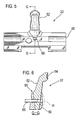
Figure 5 is a side elevation of a partly assembled lever assembly of the present invention; -
Figure 6 is a cross-sectional view on the plane G-G ofFig. 5 ; -
Figure 7 is an enlarged view of section H ofFig. 6 ; and -
Figure 8 is a perspective view of the fully assembled lever of the present invention. -
Figure 1 illustrates a general sectional view of avehicle brake assembly 10. Thevehicle brake assembly 10 includes acaliper 12 that may be constructed from one or more portions. Abridge portion 12b of thecaliper 12 is arranged to straddle arotor 14 and hasbrake pads 16, or friction elements, arranged on either side of the planar surfaces of therotor 14. Thecaliper 12 further includes ahousing portion 12a. Thehousing portion 12a andbridge portion 12b, which in this embodiment are formed from separate pieces. In other embodiments the two portions may be integral. The entire caliper is able to slide parallel to axis X on acarrier 11. The carrier further provides support for the friction elements in a circumferential and radially inwards direction. - An actuator 18 (illustrated schematically), typically an air chamber, actuates a
brake mechanism 30 to directly force onbrake pad 16 into engagement with therotor 14. Theother brake pad 16 is brought into contact with therotor 14 due to the sliding action of thecaliper 12 relative to the rotor. Theactuator 18 drives apush rod 20 through a push rod opening 21 to rotate alever assembly 22 about a pivot point P. Thelever assembly 22 includes aneccentric cam 24 having aprofile 25 that cooperates with thebrake mechanism 30 to drive thebrake pads 16. Thecam 24 amplifies the force supplied by theactuator 18 when it is transmitted viamechanism 30 to thepads 16. Thecam 24 is preferably received at least partially within abearing block 26 supporting a plurality ofneedle bearings 28 within thehousing 12. It should be understood that various actuating systems which are operated by a lever will benefit from the present invention. - The opening 31 (
Figure 4 ) of the housing, which receives thebrake mechanism 30 is closed off on the front side. That is, in the position facing thebrake rotor 14, by aclosing plate 32 which preferably at least partially supports thebrake mechanism 30. Theclosing plate 32 is attached to thehousing portion 12a by fasteners such asbolts 34 or the like. Sealing elements (not shown) are preferably located upon the sealing surfaces between theclosing plate 32 and thehousing portion 12a. - In operation, upon actuation of the brake pedal by the vehicle operator, a pneumatic output is typically produced by a
control module 33 to energize theactuator 18. Heavy-duty vehicle brake assemblies typically include a pair of pistons 36 (Figure 2 ) that transmit the force generated by theactuator 18 through thepush rod 20 andlever assembly 22 to thebrake pads 16. Thepads 16 effectively clamp against opposite faces of therotor 14 and generate frictional drag forces to retard rotation of the rotor and hence the wheel with which it is associated. It is to be understood that any suitable number ofpistons 36 may be used. - As the friction material of the
brake pads 16 wears, the rest position of the pads is adjusted by anadjuster mechanism 38 positioned betweenpistons 36 to provide the correct running clearance for the brake. The operation of such mechanisms is well known in the art, and does not form part of the present invention. - Referring to
Figures 5, 6 and8 thelever assembly 22 includes anoperating shaft 50 and alever 52 mounted thereto. - The
operating shaft 50 includes thecams 24. It should be understood thatvarious operating shaft 50 profiles will benefit from the present invention. Theoperating shaft 50 further includes atapered lever aperture 62 arranged transverse the axis of rotation P of the operating shaft on thecams 24. Atapering bore 64 extends through the walls of thelever aperture 62 substantially at right angles thereto. - The
lever 52 includes a cuppedsegment 54 for receipt of the push rod 20 (Figure 1 ). It should be understood that levers of a specific design, such as a desired length specific to aparticular brake assembly 10 may be interchangeably assembled to acommon operating shaft 50 according to the present invention. Likewise, operating shafts of a design specific to aparticular brake assembly 10 may be interchangeably assembled with a common lever according to the present invention. - A
taper pin portion 56 and atransverse bore 58 are formed directly into thelever 52. That is, thelever 52 is preferably manufactured from a single piece of material to provide high strength. Thelever 52 may also be manufactured of a material different than theoperating shaft 50 to further increase the strength thereof. - An
interface 55 between thelever aperture 62 of theoperating shaft 50 and thetaper pin portion 56 of thelever 52 includes an orientation feature such that thelever 52 can only be mounted to theoperating shaft 50 in a proper orientation. In other words, thecupped segment 54 for receipt of thepush rod 20 is properly located. Theorientation feature 55 is in this embodiment provided by making thetaper pin portion 56 andlever aperture 62 oval in cross-section rather than circular. In other embodiments a key and slot arrangement could alternatively be used, for example. - Referring to
Figure 4 , an assembly sequence for thelever assembly 22 is illustrated. Theoperating shaft 50 is assembled into thehousing portion 12a. Theoperating shaft 50 is assembled into the housing such that thelever aperture 62 is generally orientated towards the push rod opening 21. Thelever 52 is passed through the push rod opening 21 and into thelever aperture 62. - Then, with particular reference to
Figs. 4 ,6 and7 , a taperingretainer pin 66 is inserted intobore 64 from the housing opening 31. When hand fitted together, an offset A exists betweenbores retainer pin 66 is forced home the offset is reduced or removed and a secure connection betweenlever 52 and operatingshaft 50 is created as shown inFig. 8 . - The
brake mechanism 30, closingplate 32,housing portion 12a andbridge portion 12b may then be assembled together. In its assembled state, theretainer pin 66 does not interfere with operation of thebrake mechanism 30 oradjuster mechanism 38. - By utilising a two-piece lever assembly, the needs of particular heavy vehicle applications can be met with a minimal number of interchangeable operating shaft and lever portions, rather than multiple complete lever assemblies, thus minimising the number of separate component castings needed, and inventory to be carried.
- The foregoing description is exemplary rather than defined by the limitations within. Many modifications and variations of the present invention are possible in light of the above teachings. The preferred embodiments of this invention have been disclosed, however, one of ordinary skill in the art would recognize that certain modifications would come within the scope of this invention. It is, therefore, to be understood that within the scope of the appended claims, the invention may be practiced otherwise than as specifically described. In particular the invention may be employed in differing types of brake, such as fixed caliper, sliding rotor brakes. An additional aperture may be provided in the underside of the brake housing specifically for the insertion of the lever, rather than assembling it through the lever aperture. Furthermore, an aperture may be provided in the rear of the housing to allow the retainer pin to be inserted to secure the lever to the operating shaft after the brake mechanism has been fitted to the housing. In turn, this would permit the lever to be inserted into the lever aperture in the final stages of brake. It will, of course, be apparent that, in the variant, the bores in which the retainer pin fit would taper in the opposite direction. The retainer pin may be provided with some means to ensure its positive securement in the complementary bores. For example, the thinnest end of the pin may be threaded such that a nut and washer can be secured to the pin to hold it in the required position. The nut could also be used to draw the pin through the bore, as an alternative to driving the pin home.
Claims (10)
- A lever assembly (22) for a vehicle brake (10) comprising:an operating shaft (50) comprising a lever aperture (62);a lever (52) engageable with said lever aperture; anda retainer pin (64) insertable into the assembly to retain the lever in the lever aperture.
- The lever assembly as recited in claim 1, wherein the lever aperture is tapered and the lever has a corresponding taper pin portion (56).
- The lever assembly as recited in claim 1 or 2, wherein the retainer pin is insertable into a first bore (64) in the operating shaft and a second bore (58) in the lever.
- The lever assembly as recited in claim 3, wherein the bores are axially offset when push fitted, but may be brought into substantial axial alignment when the retainer pin is driven home.
- The lever assembly as recited in claim 3 or claim 4, wherein the retainer pin and first and second bores are tapered.
- The lever assembly as recited in any preceding claim, further comprising an anti-rotation feature between said lever and said operating shaft.
- A brake caliper incorporating a lever assembly according to any preceding claim.
- A method of assembling a lever assembly (22) into a vehicle brake housing (12a) comprising the steps of:(1) assembling an operating shaft (50) comprising a lever aperture (62) into a brake housing portion (12a) through a first opening (31); and(2) passing a lever (52) through a second opening (21) in said brake housing into the lever aperture; and(3) inserting a retainer pin into the assembly to retain the lever in the lever aperture.
- A method as recited in claim 8, wherein said second opening is a push rod opening (21).
- A method as recited in claim 8 or claim 9, wherein in step (3) the retainer pin is driven home to retain the lever in the lever aperture.
Priority Applications (7)
| Application Number | Priority Date | Filing Date | Title |
|---|---|---|---|
| EP04256574A EP1650464B1 (en) | 2004-10-25 | 2004-10-25 | Lever assembly for a vehicle brake and method of assembly therefor |
| AT04256574T ATE403814T1 (en) | 2004-10-25 | 2004-10-25 | BRAKE LEVER ASSEMBLY FOR MOTOR VEHICLE AND METHOD OF ASSEMBLY |
| DE602004015613T DE602004015613D1 (en) | 2004-10-25 | 2004-10-25 | Brake lever assembly for motor vehicle and method of assembly |
| US11/248,007 US20060086575A1 (en) | 2004-10-25 | 2005-10-11 | Lever assembly for a vehicle brake and method of assembly therefor |
| JP2005303911A JP2006117236A (en) | 2004-10-25 | 2005-10-19 | Lever assembly for vehicle brake, and method of assembling the same |
| CN200510114541.8A CN1766361A (en) | 2004-10-25 | 2005-10-24 | Lever assembly for a vehicle brake and method of assembly therefor |
| BRPI0505471-0A BRPI0505471A (en) | 2004-10-25 | 2005-10-25 | lever mechanism for a vehicle brake and mounting method |
Applications Claiming Priority (1)
| Application Number | Priority Date | Filing Date | Title |
|---|---|---|---|
| EP04256574A EP1650464B1 (en) | 2004-10-25 | 2004-10-25 | Lever assembly for a vehicle brake and method of assembly therefor |
Publications (2)
| Publication Number | Publication Date |
|---|---|
| EP1650464A1 EP1650464A1 (en) | 2006-04-26 |
| EP1650464B1 true EP1650464B1 (en) | 2008-08-06 |
Family
ID=34930753
Family Applications (1)
| Application Number | Title | Priority Date | Filing Date |
|---|---|---|---|
| EP04256574A Not-in-force EP1650464B1 (en) | 2004-10-25 | 2004-10-25 | Lever assembly for a vehicle brake and method of assembly therefor |
Country Status (7)
| Country | Link |
|---|---|
| US (1) | US20060086575A1 (en) |
| EP (1) | EP1650464B1 (en) |
| JP (1) | JP2006117236A (en) |
| CN (1) | CN1766361A (en) |
| AT (1) | ATE403814T1 (en) |
| BR (1) | BRPI0505471A (en) |
| DE (1) | DE602004015613D1 (en) |
Families Citing this family (7)
| Publication number | Priority date | Publication date | Assignee | Title |
|---|---|---|---|---|
| CN101688553B (en) * | 2007-06-28 | 2013-09-04 | Ntn株式会社 | Rocking bearing outer ring, rocking bearing, air disc brake device, fitting structure for rocking bearing outer ring |
| CN102265055B (en) | 2009-06-15 | 2014-03-12 | 丰田自动车株式会社 | Method for manufacturing friction material, friction material and braking device |
| KR101052184B1 (en) * | 2009-10-15 | 2011-07-27 | 상신이엔지 주식회사 | Accessory assembly device for automobile brake pads |
| US8662260B2 (en) * | 2011-06-10 | 2014-03-04 | Ausco Products, Inc. | Ball ramp caliper brake |
| DE102014111954B4 (en) * | 2014-08-21 | 2016-06-16 | Knorr-Bremse Systeme für Nutzfahrzeuge GmbH | Brake swivel lever for a disc brake |
| EA030854B1 (en) * | 2015-12-15 | 2018-10-31 | Публичное акционерное общество "КАМАЗ" | Disk braking mechanism |
| EP3492767B1 (en) * | 2017-11-29 | 2020-11-18 | Meritor Heavy Vehicle Braking Systems (UK) Limited | A disc brake |
Family Cites Families (47)
| Publication number | Priority date | Publication date | Assignee | Title |
|---|---|---|---|---|
| US2026A (en) * | 1841-04-02 | Improvement in cotton-presses | ||
| US2487696A (en) * | 1947-12-06 | 1949-11-08 | Coffing Hoist Company | Combination tool and handle |
| US2656018A (en) * | 1949-02-04 | 1953-10-20 | Westinghouse Air Brake Co | Brake apparatus |
| US2650681A (en) * | 1950-02-16 | 1953-09-01 | Roy H Shively | Brake adjusting apparatus |
| US2926758A (en) * | 1957-10-23 | 1960-03-01 | Westinghouse Air Brake Co | Hydro-pneumatic type tread brake unit for railway cars |
| US2952486A (en) * | 1957-11-27 | 1960-09-13 | Mobay Chemical Corp | Elastic coupling for jointed members |
| US2940554A (en) * | 1958-12-23 | 1960-06-14 | Westinghouse Air Brake Co | Railway wheel tread brake unit |
| DE2057322C3 (en) * | 1970-11-21 | 1981-03-12 | Alfred Teves Gmbh, 6000 Frankfurt | Actuating device for a partially lined disc brake |
| US3776329A (en) * | 1971-03-19 | 1973-12-04 | Self Energizing Disc Brakes Lt | Brake wear and adjustment device |
| DE2617621C2 (en) * | 1976-04-22 | 1982-11-18 | Gardena Kress + Kastner Gmbh, 7900 Ulm | System of various garden tools |
| US4189952A (en) * | 1977-11-14 | 1980-02-26 | Allis-Chalmers Corporation | Vehicle transmission shifting mechanism |
| US4499978A (en) * | 1981-11-09 | 1985-02-19 | C. S. Norcross & Sons | Slack adjuster |
| SE8202163L (en) * | 1982-04-05 | 1983-10-06 | Sab Nife Ab | DISC BUMPER FOR A RAILWAY VEHICLE |
| US4879964A (en) * | 1988-09-12 | 1989-11-14 | Emerson Jr Donald L | Air brake adjustment marker |
| US5038895A (en) * | 1988-10-24 | 1991-08-13 | Kelsey-Hayes Company | Automatic adjusting mechanism for a disc brake assembly having a mechanically actuated parking brake |
| US5251723A (en) * | 1989-02-23 | 1993-10-12 | Sparton Corporation | Service brake and shift lever interlock system |
| US5036958A (en) * | 1989-08-28 | 1991-08-06 | Krestbuch Engineering, Inc. | Automatic slack adjuster for vehicle brakes |
| DE4127730A1 (en) * | 1991-08-22 | 1993-03-04 | Ford Werke Ag | SHIFT LEVER BEARING FOR TRANSMISSION OF MOTOR VEHICLES |
| US5309783A (en) * | 1992-02-06 | 1994-05-10 | Dura Mechanical Components, Inc. | Simplified automatic transmission shifter |
| US5220985A (en) * | 1992-05-04 | 1993-06-22 | General Motors Corporation | Shift range selection mechanism for an automatic transmission |
| EP0569031B1 (en) * | 1992-05-08 | 1995-11-29 | DEUTSCHE PERROT-BREMSE GmbH | Adjuster device for a disc brake |
| DE4231560C2 (en) * | 1992-09-21 | 2002-07-11 | Perrot Bremse Gmbh Deutsche | Actuator for a sliding caliper disc brake |
| US5328285A (en) * | 1992-09-29 | 1994-07-12 | Grubbs Gary L | Articulated gear shift lever joint assembly |
| DE4323292A1 (en) * | 1993-07-12 | 1995-01-19 | Perrot Bremse Gmbh Deutsche | Adjustment device for a disc brake |
| US5415448A (en) * | 1993-08-11 | 1995-05-16 | Ixl Manufacturing Company, Inc. | Universal replacement tool handle combination |
| SE505339C2 (en) * | 1994-10-24 | 1997-08-11 | Haldex Ab | Disc brake caliper |
| US5462369A (en) * | 1994-11-09 | 1995-10-31 | Span Tech Corporation | Bearing lock system |
| US5825287A (en) * | 1995-02-02 | 1998-10-20 | Indian Head Industries | Vehicle brake monitoring system |
| DE19507308A1 (en) * | 1995-03-02 | 1996-09-05 | Perrot Bremsen Gmbh | Disc brake |
| DE19515063C2 (en) * | 1995-04-27 | 2002-06-06 | Knorr Bremse Systeme | Disc brake for vehicles, in particular road vehicles |
| US5529150A (en) * | 1995-05-16 | 1996-06-25 | Hayes Industrial Brake, Inc. | Parking brake |
| USH2026H1 (en) * | 1995-10-10 | 2002-06-04 | Jay D. White | Brake service signaling system |
| WO1997018969A1 (en) * | 1995-11-22 | 1997-05-29 | Daewoo Motor Co., Ltd. | Selector lever lock device for an automatic transmission in a motor vehicle |
| DE19600819A1 (en) * | 1996-01-11 | 1997-07-17 | Perrot Bremsen Gmbh | Wear monitoring device |
| US5699880A (en) * | 1996-06-03 | 1997-12-23 | Mr. Safety Check Systems Inc | Brake adjustment indicator |
| US6286385B1 (en) * | 1997-12-02 | 2001-09-11 | Kabushiki Kaisha Tokai-Rika-Denki-Seisakusho | Shift lever device |
| GB9716363D0 (en) * | 1997-08-02 | 1997-10-08 | Lucas Ind Plc | Improvements relating to disc brakes |
| GB9806542D0 (en) * | 1998-03-26 | 1998-05-27 | Lucas Ind Plc | Disc brake actuator |
| JP2000127794A (en) * | 1998-10-30 | 2000-05-09 | Fuji Kiko Co Ltd | Shift lever device |
| US6273218B1 (en) * | 1998-11-03 | 2001-08-14 | Meritor Heavy Vehicle Systems, Llc | Vehicle brake system having a sensor to measure movement |
| US6233991B1 (en) * | 1999-01-26 | 2001-05-22 | Bryant Products, Inc. | Apparatus and method for spin forming a tube |
| US6255941B1 (en) * | 2000-02-24 | 2001-07-03 | Indian Head Industries, Inc. | Brake monitoring system |
| US6352137B1 (en) * | 2000-03-22 | 2002-03-05 | Indian Head Industries, Inc. | Brake monitoring system |
| US6390244B1 (en) * | 2001-01-17 | 2002-05-21 | Dana Corporation | Brake wear indicator |
| US6481542B2 (en) * | 2001-02-19 | 2002-11-19 | Meritor Heavy Vehicle Systems, Llc. | Brake adjuster |
| FR2824118A1 (en) * | 2001-04-25 | 2002-10-31 | Delphi Tech Inc | DRUM BRAKE AND WEAR DETECTOR FOR SUCH A BRAKE |
| US6698553B2 (en) * | 2002-03-27 | 2004-03-02 | Meritor Heavy Vehicle Technology, Llc | Disc brake chamber adapter |
-
2004
- 2004-10-25 EP EP04256574A patent/EP1650464B1/en not_active Not-in-force
- 2004-10-25 DE DE602004015613T patent/DE602004015613D1/en not_active Expired - Fee Related
- 2004-10-25 AT AT04256574T patent/ATE403814T1/en not_active IP Right Cessation
-
2005
- 2005-10-11 US US11/248,007 patent/US20060086575A1/en not_active Abandoned
- 2005-10-19 JP JP2005303911A patent/JP2006117236A/en active Pending
- 2005-10-24 CN CN200510114541.8A patent/CN1766361A/en active Pending
- 2005-10-25 BR BRPI0505471-0A patent/BRPI0505471A/en not_active Application Discontinuation
Also Published As
| Publication number | Publication date |
|---|---|
| US20060086575A1 (en) | 2006-04-27 |
| BRPI0505471A (en) | 2006-07-18 |
| CN1766361A (en) | 2006-05-03 |
| ATE403814T1 (en) | 2008-08-15 |
| JP2006117236A (en) | 2006-05-11 |
| EP1650464A1 (en) | 2006-04-26 |
| DE602004015613D1 (en) | 2008-09-18 |
Similar Documents
| Publication | Publication Date | Title |
|---|---|---|
| US20060086575A1 (en) | Lever assembly for a vehicle brake and method of assembly therefor | |
| US7331432B2 (en) | Disk brake apparatus | |
| US8011482B2 (en) | Electric actuator unit for a vehicle brake assembly | |
| KR101980225B1 (en) | Disk brake with a parking brake, mechanical thrust assembly, and method of assembling | |
| CN108884889B (en) | Shaft nut assembly with multiple stop cams | |
| US20060289253A1 (en) | Monoblock caliper housing for a disc brake assembly | |
| CN108071716B (en) | Controlled contact guide pin for vehicle disc brake | |
| JPH09512886A (en) | Actuators for vehicle brakes, especially disc brakes | |
| EP2914866B1 (en) | Guide pin for disc brake assembly, disc brake assembly including such a guide pin and method for producing a disc brake assembly including such a guide pin | |
| US9284999B2 (en) | Guide pin for disc brake assembly, disc brake assembly including such a guide pin and method for producing a disc brake assembly including such a guide pin | |
| US10626940B2 (en) | Disc brake having a synchronization unit | |
| US5111915A (en) | Sliding saddle disk brake | |
| CN109838477A (en) | Disk brake | |
| US20050168056A1 (en) | Method and apparatus for locating an axle torque plate | |
| CN108778868B (en) | Disc brake and method of manufacturing the same | |
| CN110375014B (en) | Piston brake caliper and brake system | |
| JP2005511999A (en) | Brake device for vehicle | |
| US6817452B2 (en) | Lever assembly having a selectable push rod receiving insert for a vehicle brake assembly and method of assembly therefor | |
| US20030024778A1 (en) | Conical brake assembly | |
| US20050045434A1 (en) | Vehicle brake assembly having an assembly opening and method of assembly therefor | |
| EP1475552B1 (en) | Lever assembly for a vehicle brake and method of assembly thereof | |
| JP2006194450A (en) | Disc brake | |
| JPH11182593A (en) | Duo-servo type drum braking device | |
| JP4194870B2 (en) | Disc brake | |
| CN115111291B (en) | Brake assembly |
Legal Events
| Date | Code | Title | Description |
|---|---|---|---|
| PUAI | Public reference made under article 153(3) epc to a published international application that has entered the european phase |
Free format text: ORIGINAL CODE: 0009012 |
|
| AK | Designated contracting states |
Kind code of ref document: A1 Designated state(s): AT BE BG CH CY CZ DE DK EE ES FI FR GB GR HU IE IT LI LU MC NL PL PT RO SE SI SK TR |
|
| AX | Request for extension of the european patent |
Extension state: AL HR LT LV MK |
|
| 17P | Request for examination filed |
Effective date: 20060928 |
|
| AKX | Designation fees paid |
Designated state(s): AT BE BG CH CY CZ DE DK EE ES FI FR GB GR HU IE IT LI LU MC NL PL PT RO SE SI SK TR |
|
| GRAP | Despatch of communication of intention to grant a patent |
Free format text: ORIGINAL CODE: EPIDOSNIGR1 |
|
| GRAS | Grant fee paid |
Free format text: ORIGINAL CODE: EPIDOSNIGR3 |
|
| GRAA | (expected) grant |
Free format text: ORIGINAL CODE: 0009210 |
|
| AK | Designated contracting states |
Kind code of ref document: B1 Designated state(s): AT BE BG CH CY CZ DE DK EE ES FI FR GB GR HU IE IT LI LU MC NL PL PT RO SE SI SK TR |
|
| REG | Reference to a national code |
Ref country code: GB Ref legal event code: FG4D |
|
| REG | Reference to a national code |
Ref country code: CH Ref legal event code: EP |
|
| REG | Reference to a national code |
Ref country code: IE Ref legal event code: FG4D |
|
| REF | Corresponds to: |
Ref document number: 602004015613 Country of ref document: DE Date of ref document: 20080918 Kind code of ref document: P |
|
| REG | Reference to a national code |
Ref country code: SE Ref legal event code: TRGR |
|
| PG25 | Lapsed in a contracting state [announced via postgrant information from national office to epo] |
Ref country code: ES Free format text: LAPSE BECAUSE OF FAILURE TO SUBMIT A TRANSLATION OF THE DESCRIPTION OR TO PAY THE FEE WITHIN THE PRESCRIBED TIME-LIMIT Effective date: 20081117 Ref country code: NL Free format text: LAPSE BECAUSE OF FAILURE TO SUBMIT A TRANSLATION OF THE DESCRIPTION OR TO PAY THE FEE WITHIN THE PRESCRIBED TIME-LIMIT Effective date: 20080806 |
|
| PGFP | Annual fee paid to national office [announced via postgrant information from national office to epo] |
Ref country code: CZ Payment date: 20081016 Year of fee payment: 5 |
|
| PG25 | Lapsed in a contracting state [announced via postgrant information from national office to epo] |
Ref country code: SI Free format text: LAPSE BECAUSE OF FAILURE TO SUBMIT A TRANSLATION OF THE DESCRIPTION OR TO PAY THE FEE WITHIN THE PRESCRIBED TIME-LIMIT Effective date: 20080806 Ref country code: FI Free format text: LAPSE BECAUSE OF FAILURE TO SUBMIT A TRANSLATION OF THE DESCRIPTION OR TO PAY THE FEE WITHIN THE PRESCRIBED TIME-LIMIT Effective date: 20080806 Ref country code: AT Free format text: LAPSE BECAUSE OF FAILURE TO SUBMIT A TRANSLATION OF THE DESCRIPTION OR TO PAY THE FEE WITHIN THE PRESCRIBED TIME-LIMIT Effective date: 20080806 |
|
| PG25 | Lapsed in a contracting state [announced via postgrant information from national office to epo] |
Ref country code: BE Free format text: LAPSE BECAUSE OF FAILURE TO SUBMIT A TRANSLATION OF THE DESCRIPTION OR TO PAY THE FEE WITHIN THE PRESCRIBED TIME-LIMIT Effective date: 20080806 |
|
| PGFP | Annual fee paid to national office [announced via postgrant information from national office to epo] |
Ref country code: IT Payment date: 20081025 Year of fee payment: 5 Ref country code: SE Payment date: 20081022 Year of fee payment: 5 |
|
| PG25 | Lapsed in a contracting state [announced via postgrant information from national office to epo] |
Ref country code: BG Free format text: LAPSE BECAUSE OF FAILURE TO SUBMIT A TRANSLATION OF THE DESCRIPTION OR TO PAY THE FEE WITHIN THE PRESCRIBED TIME-LIMIT Effective date: 20081106 Ref country code: DK Free format text: LAPSE BECAUSE OF FAILURE TO SUBMIT A TRANSLATION OF THE DESCRIPTION OR TO PAY THE FEE WITHIN THE PRESCRIBED TIME-LIMIT Effective date: 20080806 |
|
| PGFP | Annual fee paid to national office [announced via postgrant information from national office to epo] |
Ref country code: FR Payment date: 20081014 Year of fee payment: 5 |
|
| PG25 | Lapsed in a contracting state [announced via postgrant information from national office to epo] |
Ref country code: SK Free format text: LAPSE BECAUSE OF FAILURE TO SUBMIT A TRANSLATION OF THE DESCRIPTION OR TO PAY THE FEE WITHIN THE PRESCRIBED TIME-LIMIT Effective date: 20080806 Ref country code: RO Free format text: LAPSE BECAUSE OF FAILURE TO SUBMIT A TRANSLATION OF THE DESCRIPTION OR TO PAY THE FEE WITHIN THE PRESCRIBED TIME-LIMIT Effective date: 20080806 Ref country code: PT Free format text: LAPSE BECAUSE OF FAILURE TO SUBMIT A TRANSLATION OF THE DESCRIPTION OR TO PAY THE FEE WITHIN THE PRESCRIBED TIME-LIMIT Effective date: 20090106 Ref country code: MC Free format text: LAPSE BECAUSE OF NON-PAYMENT OF DUE FEES Effective date: 20081031 |
|
| REG | Reference to a national code |
Ref country code: CH Ref legal event code: PL |
|
| PLBE | No opposition filed within time limit |
Free format text: ORIGINAL CODE: 0009261 |
|
| STAA | Information on the status of an ep patent application or granted ep patent |
Free format text: STATUS: NO OPPOSITION FILED WITHIN TIME LIMIT |
|
| 26N | No opposition filed |
Effective date: 20090507 |
|
| REG | Reference to a national code |
Ref country code: IE Ref legal event code: MM4A |
|
| GBPC | Gb: european patent ceased through non-payment of renewal fee |
Effective date: 20081106 |
|
| PG25 | Lapsed in a contracting state [announced via postgrant information from national office to epo] |
Ref country code: EE Free format text: LAPSE BECAUSE OF FAILURE TO SUBMIT A TRANSLATION OF THE DESCRIPTION OR TO PAY THE FEE WITHIN THE PRESCRIBED TIME-LIMIT Effective date: 20080806 |
|
| PG25 | Lapsed in a contracting state [announced via postgrant information from national office to epo] |
Ref country code: DE Free format text: LAPSE BECAUSE OF NON-PAYMENT OF DUE FEES Effective date: 20090501 |
|
| PG25 | Lapsed in a contracting state [announced via postgrant information from national office to epo] |
Ref country code: CH Free format text: LAPSE BECAUSE OF NON-PAYMENT OF DUE FEES Effective date: 20081031 Ref country code: IE Free format text: LAPSE BECAUSE OF NON-PAYMENT OF DUE FEES Effective date: 20081025 Ref country code: LI Free format text: LAPSE BECAUSE OF NON-PAYMENT OF DUE FEES Effective date: 20081031 |
|
| PG25 | Lapsed in a contracting state [announced via postgrant information from national office to epo] |
Ref country code: GB Free format text: LAPSE BECAUSE OF NON-PAYMENT OF DUE FEES Effective date: 20081106 |
|
| PG25 | Lapsed in a contracting state [announced via postgrant information from national office to epo] |
Ref country code: PL Free format text: LAPSE BECAUSE OF FAILURE TO SUBMIT A TRANSLATION OF THE DESCRIPTION OR TO PAY THE FEE WITHIN THE PRESCRIBED TIME-LIMIT Effective date: 20080806 |
|
| EUG | Se: european patent has lapsed | ||
| REG | Reference to a national code |
Ref country code: FR Ref legal event code: ST Effective date: 20100630 |
|
| PG25 | Lapsed in a contracting state [announced via postgrant information from national office to epo] |
Ref country code: CY Free format text: LAPSE BECAUSE OF FAILURE TO SUBMIT A TRANSLATION OF THE DESCRIPTION OR TO PAY THE FEE WITHIN THE PRESCRIBED TIME-LIMIT Effective date: 20080806 Ref country code: LU Free format text: LAPSE BECAUSE OF NON-PAYMENT OF DUE FEES Effective date: 20081025 Ref country code: FR Free format text: LAPSE BECAUSE OF NON-PAYMENT OF DUE FEES Effective date: 20091102 Ref country code: HU Free format text: LAPSE BECAUSE OF FAILURE TO SUBMIT A TRANSLATION OF THE DESCRIPTION OR TO PAY THE FEE WITHIN THE PRESCRIBED TIME-LIMIT Effective date: 20090207 |
|
| PG25 | Lapsed in a contracting state [announced via postgrant information from national office to epo] |
Ref country code: CZ Free format text: LAPSE BECAUSE OF NON-PAYMENT OF DUE FEES Effective date: 20091025 Ref country code: TR Free format text: LAPSE BECAUSE OF FAILURE TO SUBMIT A TRANSLATION OF THE DESCRIPTION OR TO PAY THE FEE WITHIN THE PRESCRIBED TIME-LIMIT Effective date: 20080806 |
|
| PG25 | Lapsed in a contracting state [announced via postgrant information from national office to epo] |
Ref country code: GR Free format text: LAPSE BECAUSE OF FAILURE TO SUBMIT A TRANSLATION OF THE DESCRIPTION OR TO PAY THE FEE WITHIN THE PRESCRIBED TIME-LIMIT Effective date: 20081107 |
|
| PG25 | Lapsed in a contracting state [announced via postgrant information from national office to epo] |
Ref country code: IT Free format text: LAPSE BECAUSE OF NON-PAYMENT OF DUE FEES Effective date: 20091025 |
|
| PG25 | Lapsed in a contracting state [announced via postgrant information from national office to epo] |
Ref country code: SE Free format text: LAPSE BECAUSE OF NON-PAYMENT OF DUE FEES Effective date: 20091026 |