EP1650345B1 - Steuerungsvorrichtung der Dampfzufuhr in einem Bügeleisen - Google Patents
Steuerungsvorrichtung der Dampfzufuhr in einem Bügeleisen Download PDFInfo
- Publication number
- EP1650345B1 EP1650345B1 EP05109798A EP05109798A EP1650345B1 EP 1650345 B1 EP1650345 B1 EP 1650345B1 EP 05109798 A EP05109798 A EP 05109798A EP 05109798 A EP05109798 A EP 05109798A EP 1650345 B1 EP1650345 B1 EP 1650345B1
- Authority
- EP
- European Patent Office
- Prior art keywords
- actuation
- command device
- steam
- handle
- electric switch
- Prior art date
- Legal status (The legal status is an assumption and is not a legal conclusion. Google has not performed a legal analysis and makes no representation as to the accuracy of the status listed.)
- Expired - Lifetime
Links
Images

Classifications
-
- D—TEXTILES; PAPER
- D06—TREATMENT OF TEXTILES OR THE LIKE; LAUNDERING; FLEXIBLE MATERIALS NOT OTHERWISE PROVIDED FOR
- D06F—LAUNDERING, DRYING, IRONING, PRESSING OR FOLDING TEXTILE ARTICLES
- D06F75/00—Hand irons
- D06F75/08—Hand irons internally heated by electricity
- D06F75/10—Hand irons internally heated by electricity with means for supplying steam to the article being ironed
- D06F75/14—Hand irons internally heated by electricity with means for supplying steam to the article being ironed the steam being produced from water in a reservoir carried by the iron
- D06F75/18—Hand irons internally heated by electricity with means for supplying steam to the article being ironed the steam being produced from water in a reservoir carried by the iron the water being fed slowly, e.g. drop by drop, from the reservoir to a steam generator
-
- D—TEXTILES; PAPER
- D06—TREATMENT OF TEXTILES OR THE LIKE; LAUNDERING; FLEXIBLE MATERIALS NOT OTHERWISE PROVIDED FOR
- D06F—LAUNDERING, DRYING, IRONING, PRESSING OR FOLDING TEXTILE ARTICLES
- D06F75/00—Hand irons
- D06F75/34—Handles; Handle mountings
Definitions
- the present invention concerns a command device for delivering steam in an iron.
- the command device according to the present invention is arranged in correspondence with the handle of the iron and is in a position easily accessible for the user, in order to actuate the iron without detaching the hand from the handle and with the hand in any position whatsoever.
- a command device as described in document EP-A-1 043 441 , is known to deliver steam in an iron, which comprises a button arranged on the handle to selectively activate an electric switch located inside the handle and suitable to command the delivery of the steam from the plate of the iron.
- the user activates the delivery of the steam numerous times in order to make said operation more effective and to facilitate it, particularly in points which are difficult to reach or resistant to ironing.
- the button is positioned so as to be easily reachable by the user without taking his hand from the handle and without inducing torsions or efforts.
- a button is known, arranged in the front part of the handle, at the upper part or laterally with respect to the latter, but this button has the disadvantage that it can be actuated only with respect to a specific direction, parallel to the axis of actuation, so that when driven it constrains the orientation that the hand, gripping the handle, must assume in order to act on the button.
- a command device for the selective delivery of steam, having a single button that can be arranged in advance in a position chosen from two alternative positions, so as to be used both by right-handed and also by left-handed users.
- This command device cannot be activated when the button is in an intermediate position between said two alternative positions, so that, once positioned, it once again has the disadvantages of traditional buttons.
- a command device having two or more buttons, which therefore allow a corresponding different number of directions of actuation and hence a greater ease of drive even when the hand is in different positions.
- buttons corresponds to an equal number of electric switches, which makes the electric circuit more complicated and subject to breakdowns; it also makes the mechanical assembly and maintenance more complex.
- One purpose of the present invention is to achieve a command device for the delivery of steam in an iron which can be actuated by a user simply and easily and from several different directions; that is, with a wider range of positions of the hand gripping the handle, and which at the same time uses a single electric switch associated with the button.
- Another purpose of the present invention is to obtain the possibility that the steam command can be driven both by left handed users and also by right handed users, with an equal number of ranges of position of the hand for actuation.
- the Applicant has devised, tested and embodied the present invention to overcome the shortcomings of the state of the art and to obtain these and other purposes and advantages.
- a command device is used to deliver steam in an iron.
- the latter comprises a handle normally arranged on a median plane that passes through the iron longitudinally, and a circuit to deliver the steam.
- the command device comprises an electric switch arranged in the handle, associated with the circuit to deliver the steam, and actuation means arranged on the front part of the handle to be selectively activated with the hand gripping the handle, which are connected to the electric switch in order to activate the delivery of the steam.
- the actuation means are shaped so as to at least partly surround the front part of the handle and are able to be actuated both frontally and laterally and from above with respect to the handle in order to cause the electric switch to be actuated.
- the command device can be driven simply and easily and offers a plurality of actuation directions corresponding to a range of positions of the hand gripping the handle, with the farther advantage that it uses only one electric switch.
- the command device can be driven irrespectively by both left handed and right handed users.
- constraint means are provided to constrain the actuation means to the iron, more particularly, to its handle, and clamping means to keep at least part of the actuation means selectively and temporarily thrust against the electric switch.
- the actuation means have a first inactive position in which the electric switch is not actuated and therefore there is no delivery of steam; a second activation position, to activate the delivery of steam; and a third position to keep the steam delivery active, without the user needing to keep the actuation means pressed.
- the second actuation position is reached by means of driving the actuation means, effected by the user and determined by the constraint means; this drive takes at least part of the actuation means into contact with the electric switch in order to start the steam delivery.
- the clamping means are activated so as to keep and clamp the actuation means against the electric switch. This position is maintained until, with a suitable drive, the user de-activates the clamping means and thus allows the actuation means to return to the first inactive position.
- the actuation means comprise a first actuation element connected to the electric switch and a second actuation element associated with the first actuation element, and able to cooperate with the latter in order to actuate the electric switch.
- the second actuation element has a high extension according to at least one axis, advantageously along the handle, so as to further facilitate the activation of the steam delivery, which can occur for example by means of pressure with the palm of the hand.
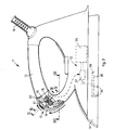
- a command device 10 is applied for the delivery of steam and is arranged in the front part of an iron 11.
- the iron 11 ( fig. 2 ) comprises a handle 13 arranged on a median plane which passes through the iron 11 longitudinally, a metal ironing plate 14, heated by means of electric resistances, an electric cable 19 to feed the various devices inside the iron 11, and a circuit to deliver the steam 12.
- the circuit to deliver the steam 12, of known type, comprises as schematized in fig. 2 , a boiler 35 where the water is heated, for example by means of an electric resistance, and a plurality of through holes 36, only partly shown here, arranged on the ironing plate 14, from which the steam selectively emerges.
- the circuit to deliver the steam 12 also comprises an electrically commanded valve, or electrovalve 37, which is connected upstream with the boiler 35 and downstream, by means of a plurality of pipes 38, only partly shown, with the through holes 36.
- the electrovalve 37 can be selectively opened to obtain the delivery of the steam.
- the command device 10 comprises an electric switch 15 of a known type, arranged inside the handle 13, having a mushroom-shaped actuator 16 and connected to the electrovalve 37 of the circuit to deliver the steam 12.
- the user By actuating the command device 10, the user causes the electrovalve 37 to be activated and hence the delivery of the steam on the ironing plate through the through holes 36.
- the command device 10 also comprises a first button 17 and a second button 18, made of synthetic material, or any material suitable for the purpose.
- the first button 17 is located on the front part of the handle 13, is arranged on the median plane and is connected to the electric switch 15 to activate the delivery of the steam.
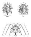
- the second button 18 is associated with the first button 17 and comprises two fins 26 ( fig. 1 ), lateral and opposite, shaped so as to at least partly surround the first button 17 and the front part of the handle 13.
- the second button 18 also comprises a lower zone 27, elongated in shape, which extends into the front zone of the iron 11.
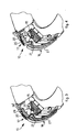
- the first button 17 ( figs. 3, 4 , 5 and 6 ) has a knurled outer zone 20 and two walls 21 arranged inside the handle 13, opposite each other and parallel to the median plane.
- An intermediate wall 22 is arranged between the two walls 21, parallel to them and able to contact the underlying actuator 16 of the electric switch 15.
- Each wall 21 comprises an attachment element 24 ( figs. 5 and 6 ), cylindrical in shape, made in a single piece and able to be hinged in a respective seating 25 made inside each fin 26 of the second button 18.
- the first button 17 can rotate with respect to the seatings 25, parallel to the median plane and according to the direction of the upper arrow shown in fig. 2 .
- the lower zone 27 of the second button 18 ( fig. 7 ) comprises two arms 32 made in a single piece and inserted inside the handle 13. Each of the two arms 32 has a cylindrical seating 34 parallel to the median plane. In the two cylindrical seatings 34 a tubular element 33 is inserted which is attached to the handle 13 and on which the two arms 32 are free to rotate.
- the second button 18 can also rotate with respect to the tubular element 33 parallel to the median plane and according to the direction of the lower arrow shown in fig. 2 .
- the first button 17 and the second button 18 are in a first inactive position in which the intermediate wall 22 does not contact the actuator 16 of the electric switch 15 and therefore no steam is delivered.
- the first button 17 and/or the second button 18 are in a second actuation position in which the intermediate wall 22 contacts the actuator 16 of the electric switch 15 driving the delivery of the steam.
- the second actuation position is reached if the user directly actuates the first button 17 or the second button 18 in any one direction of the directions indicated by the arrows in fig. 1 , or any direction comprised among those illustrated.
- the fins 26 of the second button 18 protrude with respect to the handle 13, so that any direction of actuation on the fins 26 possesses a component parallel to the median plane and orthogonal to the external surface of the second button 18.
- the second button 18 can be actuated from any direction comprised between those shown in fig. 1 .
- the first button 17 is in a third position to keep delivery active, to reach which the first button 17 is rotated by the user so that a step 29 of the first button 17 is clamped in a mating clamping seating 30 made in the handle 13.
- the intermediate wall 22 of the first button 17 remains thrust against the actuator 16 until the user rotates the first button 17 in the opposite direction, so as to detach and distance the step 29 from the clamping seating 30.
- the user is considerably facilitated in all the ironing operations that provide the delivery of steam to the garment to be ironed.
- the command device 10 does not have the first button 17 and comprises a button shaped so as to surround the front part of the handle 13 and having a similar shape to that of the second button 18, which actuates the electric switch 15 directly.
- the command device 10 can also be used in irons having the boiler to heat the water arranged outside the iron.
- command device 10 can comprise more than two buttons, each of which is able to actuate the electric switch 15 directly or indirectly.
Landscapes
- Engineering & Computer Science (AREA)
- Textile Engineering (AREA)
- Irons (AREA)
- Supply And Distribution Of Alternating Current (AREA)
- Vending Machines For Individual Products (AREA)
- Electrical Discharge Machining, Electrochemical Machining, And Combined Machining (AREA)
- Massaging Devices (AREA)
Claims (11)
- Steuervorrichtung zur Abgabe von Dampf bei einem Bügeleisen (11), das einen Griff (13), der in einer in Längsrichtung durch das Bügeleisen (11) verlaufenden Mittelebene senkrecht angeordnet ist, und eine Abgabeschaltung für den Dampf (12) aufweist, wobei die Steuervorrichtung einen in dem Griff (13) angeordneten und der Abgabeschaltung für den Dampf (12) zugeordneten elektrischen Schalter (15) sowie eine Betätigungseinrichtung (17, 18) aufweist, die entsprechend dem Vorderteil des Griffs (13) angeordnet und mit dem elektrischen Schalter (15) verbunden ist, um die Abgabe von Dampf zu aktivieren, dadurch gekennzeichnet, dass die Betätigungseinrichtung (17, 18) so gestaltet ist, dass sie den Vorderteil des Griffs (13) mindestens teilweise umgibt, und sich sowohl von vorne als auch seitlich sowie bezüglich des Griffs (13) von oben betätigen lässt, um den elektrischen Schalter (15) zu aktivieren.
- Steuervorrichtung nach Anspruch 1, gekennzeichnet durch Rastmittel (21, 24, 25, 32, 33, 34) zum Verrasten der Betätigungseinrichtung (17, 18) mit dem Bügeleisen (11).
- Steuervorrichtung nach Anspruch 1 oder 2, gekennzeichnet durch eine Klemmeinrichtung (29, 30), die mindestens einen Teil der Betätigungseinrichtung (17, 18) selektiv und vorübergehend gegen den elektrischen Schalter (15) gedrückt hält.
- Steuervorrichtung nach Anspruch 3, dadurch gekennzeichnet, dass die Betätigungseinrichtung (17, 18) eine erste inaktive Stellung (i) aufweist, in der der elektrische Schalter (15) nicht betätigt ist, eine zweite, von den Rastmitteln (21, 24, 25, 32, 33, 34) bestimmte Betätigungsstellung (ii), in der mindestens ein Teil der Betätigungseinrichtung (17, 18) den elektrischen Schalter (15) berührt, um die Abgabe von Dampf zu aktivieren, und eine dritte Stellung (iii), die die Abgabe von Dampf aktiv hält, wobei mittels der Klemmeinrichtung (29, 30) mindestens ein Teil der Betätigungseinrichtung (17, 18) in Berührung mit dem elektrischen Schalter (15) gehalten wird.
- Steuervorrichtung nach einem der vorhergehenden Ansprüche, dadurch gekennzeichnet, dass die Betätigungseinrichtung ein erstes Betätigungselement (17), das mit dem elektrischen Schalter (15) mechanisch verbunden ist, und ein zweites Betätigungselement (18) aufweist, das dem ersten Betätigungselement (17) zugeordnet ist und mit diesem zusammenarbeitet, um den elektrischen Schalter (15) zu betätigen.
- Steuervorrichtung nach Anspruch 2 und 5, dadurch gekennzeichnet, dass zu den dem ersten Betätigungselement (17) zugeordneten Rastmitteln mindestens zwei Wände (21) mit jeweils einem Verriegelungselement (24) gehören, das in einem jeweiligen, in dem zweiten Betätigungselement (18) ausgebildeten Sitz (25) hinein schwenkbar ist.
- Steuervorrichtung nach Anspruch 2 und 5, dadurch gekennzeichnet, dass zu den dem zweiten Betätigungselement (18) zugeordneten Rastmitteln mindestens zwei Arme (32) und mindestens ein an dem Griff (13) angebrachtes Rohrelement (33) gehören, wobei die Arme (32) jeweils einen Sitz (34) aufweisen, in den das Rohrelement (33) eingreift.
- Steuervorrichtung nach einem der Ansprüche 5 bis 7, dadurch gekennzeichnet, dass das zweite Betätigungselement (18) zwei seitliche und entgegengesetzte Rippen (26) aufweist, die so gestaltet sind, dass sie das erste Betätigungselement (17) und den Vorderteil des Griffs (13) mindestens teilweise umgeben.
- Steuervorrichtung nach Anspruch 8, dadurch gekennzeichnet, dass die Rippen (26) aus dem Griff (13) herausragen.
- Steuervorrichtung nach Anspruch 3 und 5, dadurch gekennzeichnet, dass die Klemmeinrichtung (29, 30) dem ersten Betätigungselement (17) zugeordnet ist.
- Steuervorrichtung nach einem der vorhergehenden Ansprüche, dadurch gekennzeichnet, dass sie mit einer Ventileinrichtung (37) elektrisch verbunden ist, die ein oder mehrere Rohre verbindet, um Dampf (38) durch in der Arbeitsplatte (14) des Bügeleisens (11) vorhandene Löcher (36) abzugeben.
Applications Claiming Priority (1)
| Application Number | Priority Date | Filing Date | Title |
|---|---|---|---|
| IT000197A ITUD20040197A1 (it) | 2004-10-22 | 2004-10-22 | Dispositivo di comando per l'erogazione del |
Publications (2)
| Publication Number | Publication Date |
|---|---|
| EP1650345A1 EP1650345A1 (de) | 2006-04-26 |
| EP1650345B1 true EP1650345B1 (de) | 2008-07-16 |
Family
ID=34956787
Family Applications (1)
| Application Number | Title | Priority Date | Filing Date |
|---|---|---|---|
| EP05109798A Expired - Lifetime EP1650345B1 (de) | 2004-10-22 | 2005-10-20 | Steuerungsvorrichtung der Dampfzufuhr in einem Bügeleisen |
Country Status (5)
| Country | Link |
|---|---|
| EP (1) | EP1650345B1 (de) |
| AT (1) | ATE401448T1 (de) |
| DE (1) | DE602005008159D1 (de) |
| ES (1) | ES2313225T3 (de) |
| IT (1) | ITUD20040197A1 (de) |
Cited By (1)
| Publication number | Priority date | Publication date | Assignee | Title |
|---|---|---|---|---|
| DE102014100753A1 (de) * | 2014-01-23 | 2015-07-23 | Miele & Cie. Kg | Bügelgerät mit einem Dampferzeuger |
Families Citing this family (1)
| Publication number | Priority date | Publication date | Assignee | Title |
|---|---|---|---|---|
| ITMI20120742A1 (it) * | 2012-05-03 | 2013-11-04 | Pony S P A | Dispositivo di stiratura a vapore |
Family Cites Families (3)
| Publication number | Priority date | Publication date | Assignee | Title |
|---|---|---|---|---|
| JP2589716B2 (ja) * | 1987-12-03 | 1997-03-12 | 松下電器産業株式会社 | スチームアイロン |
| AU6075399A (en) * | 1998-10-27 | 2000-05-15 | Divelit Sa | Steam controlling device for steam iron |
| EP1043441A1 (de) * | 1999-04-07 | 2000-10-11 | San Marco Piccoli Elettrodomestici s.r.l. | Dampfbügeleisen mit Wasserbehälter und Pumpe |
-
2004
- 2004-10-22 IT IT000197A patent/ITUD20040197A1/it unknown
-
2005
- 2005-10-20 DE DE602005008159T patent/DE602005008159D1/de not_active Expired - Lifetime
- 2005-10-20 AT AT05109798T patent/ATE401448T1/de not_active IP Right Cessation
- 2005-10-20 ES ES05109798T patent/ES2313225T3/es not_active Expired - Lifetime
- 2005-10-20 EP EP05109798A patent/EP1650345B1/de not_active Expired - Lifetime
Cited By (1)
| Publication number | Priority date | Publication date | Assignee | Title |
|---|---|---|---|---|
| DE102014100753A1 (de) * | 2014-01-23 | 2015-07-23 | Miele & Cie. Kg | Bügelgerät mit einem Dampferzeuger |
Also Published As
| Publication number | Publication date |
|---|---|
| DE602005008159D1 (de) | 2008-08-28 |
| ITUD20040197A1 (it) | 2005-01-22 |
| ATE401448T1 (de) | 2008-08-15 |
| ES2313225T3 (es) | 2009-03-01 |
| EP1650345A1 (de) | 2006-04-26 |
Similar Documents
| Publication | Publication Date | Title |
|---|---|---|
| EP3596264B1 (de) | Vorrichtung für den häuslichen gebrauch zum bügeln von kleidung und dergleichen | |
| DE602006015520D1 (de) | Kleidungsschutzsystem | |
| EP1650345B1 (de) | Steuerungsvorrichtung der Dampfzufuhr in einem Bügeleisen | |
| US1958876A (en) | Steaming iron | |
| KR900008497B1 (ko) | 전원공급시스템에 전기적으로 접속된 기부판상에 지지된 용기로 구성된 전기 케틀 | |
| US3561662A (en) | Solder-removing device | |
| US20220053992A1 (en) | Device for the hot cleaning of various types of surfaces | |
| CN109082868B (zh) | 配备有通过第一和第二电阻加热的槽的熨烫设备 | |
| WO2005009171A1 (de) | Handluftdusche mit zwei haltegriffen | |
| RU2664238C1 (ru) | Гладильная станция с несколькими потоками пара | |
| FR2868676B1 (fr) | Appareil electrique de chauffage de liquide | |
| DE10211879A1 (de) | Bügeleisen für eine Dampfbügelvorrichtung | |
| US3080469A (en) | Wire stripping tool | |
| US1249464A (en) | Laundry appliance. | |
| KR100205188B1 (ko) | 가스기기의 점화시의 화력조정기구 | |
| US3824719A (en) | Seambuster iron | |
| US1842784A (en) | Ironing apparatus | |
| EP3135808B1 (de) | Elektrohaushaltsgerät für die wäschebehandlung mit dampf, das einen bedienungsknopf für die dampfdiffusion umfasst | |
| US10053814B2 (en) | Iron with steam channels and textured soleplate | |
| EP3947805B1 (de) | Bügelvorrichtung und verfahren zum bügeln | |
| EP2049728B1 (de) | Temperaturregler für bügelvorrichtung | |
| US1753559A (en) | Sadiron | |
| US1536271A (en) | Ironing board | |
| WO2003085189A1 (en) | Iron and plate for an iron | |
| US1718895A (en) | Switch-control mechanism |
Legal Events
| Date | Code | Title | Description |
|---|---|---|---|
| PUAI | Public reference made under article 153(3) epc to a published international application that has entered the european phase |
Free format text: ORIGINAL CODE: 0009012 |
|
| AK | Designated contracting states |
Kind code of ref document: A1 Designated state(s): AT BE BG CH CY CZ DE DK EE ES FI FR GB GR HU IE IS IT LI LT LU LV MC NL PL PT RO SE SI SK TR |
|
| AX | Request for extension of the european patent |
Extension state: AL BA HR MK YU |
|
| 17P | Request for examination filed |
Effective date: 20061025 |
|
| AKX | Designation fees paid |
Designated state(s): AT BE BG CH CY CZ DE DK EE ES FI FR GB GR HU IE IS IT LI LT LU LV MC NL PL PT RO SE SI SK TR |
|
| GRAP | Despatch of communication of intention to grant a patent |
Free format text: ORIGINAL CODE: EPIDOSNIGR1 |
|
| GRAS | Grant fee paid |
Free format text: ORIGINAL CODE: EPIDOSNIGR3 |
|
| GRAA | (expected) grant |
Free format text: ORIGINAL CODE: 0009210 |
|
| AK | Designated contracting states |
Kind code of ref document: B1 Designated state(s): AT BE BG CH CY CZ DE DK EE ES FI FR GB GR HU IE IS IT LI LT LU LV MC NL PL PT RO SE SI SK TR |
|
| REG | Reference to a national code |
Ref country code: GB Ref legal event code: FG4D |
|
| RIN1 | Information on inventor provided before grant (corrected) |
Inventor name: RIGO, FLAVIO Inventor name: ANTONEL, ALESSANDRO |
|
| REG | Reference to a national code |
Ref country code: CH Ref legal event code: EP |
|
| REF | Corresponds to: |
Ref document number: 602005008159 Country of ref document: DE Date of ref document: 20080828 Kind code of ref document: P |
|
| REG | Reference to a national code |
Ref country code: IE Ref legal event code: FG4D |
|
| REG | Reference to a national code |
Ref country code: GR Ref legal event code: EP Ref document number: 20080402800 Country of ref document: GR |
|
| NLV1 | Nl: lapsed or annulled due to failure to fulfill the requirements of art. 29p and 29m of the patents act | ||
| PG25 | Lapsed in a contracting state [announced via postgrant information from national office to epo] |
Ref country code: NL Free format text: LAPSE BECAUSE OF FAILURE TO SUBMIT A TRANSLATION OF THE DESCRIPTION OR TO PAY THE FEE WITHIN THE PRESCRIBED TIME-LIMIT Effective date: 20080716 Ref country code: LT Free format text: LAPSE BECAUSE OF FAILURE TO SUBMIT A TRANSLATION OF THE DESCRIPTION OR TO PAY THE FEE WITHIN THE PRESCRIBED TIME-LIMIT Effective date: 20080716 Ref country code: IS Free format text: LAPSE BECAUSE OF FAILURE TO SUBMIT A TRANSLATION OF THE DESCRIPTION OR TO PAY THE FEE WITHIN THE PRESCRIBED TIME-LIMIT Effective date: 20081116 |
|
| PG25 | Lapsed in a contracting state [announced via postgrant information from national office to epo] |
Ref country code: LV Free format text: LAPSE BECAUSE OF FAILURE TO SUBMIT A TRANSLATION OF THE DESCRIPTION OR TO PAY THE FEE WITHIN THE PRESCRIBED TIME-LIMIT Effective date: 20080716 Ref country code: FI Free format text: LAPSE BECAUSE OF FAILURE TO SUBMIT A TRANSLATION OF THE DESCRIPTION OR TO PAY THE FEE WITHIN THE PRESCRIBED TIME-LIMIT Effective date: 20080716 Ref country code: BG Free format text: LAPSE BECAUSE OF FAILURE TO SUBMIT A TRANSLATION OF THE DESCRIPTION OR TO PAY THE FEE WITHIN THE PRESCRIBED TIME-LIMIT Effective date: 20081016 Ref country code: PT Free format text: LAPSE BECAUSE OF FAILURE TO SUBMIT A TRANSLATION OF THE DESCRIPTION OR TO PAY THE FEE WITHIN THE PRESCRIBED TIME-LIMIT Effective date: 20081216 Ref country code: SI Free format text: LAPSE BECAUSE OF FAILURE TO SUBMIT A TRANSLATION OF THE DESCRIPTION OR TO PAY THE FEE WITHIN THE PRESCRIBED TIME-LIMIT Effective date: 20080716 Ref country code: AT Free format text: LAPSE BECAUSE OF FAILURE TO SUBMIT A TRANSLATION OF THE DESCRIPTION OR TO PAY THE FEE WITHIN THE PRESCRIBED TIME-LIMIT Effective date: 20080716 |
|
| REG | Reference to a national code |
Ref country code: ES Ref legal event code: FG2A Ref document number: 2313225 Country of ref document: ES Kind code of ref document: T3 |
|
| PG25 | Lapsed in a contracting state [announced via postgrant information from national office to epo] |
Ref country code: BE Free format text: LAPSE BECAUSE OF FAILURE TO SUBMIT A TRANSLATION OF THE DESCRIPTION OR TO PAY THE FEE WITHIN THE PRESCRIBED TIME-LIMIT Effective date: 20080716 |
|
| PG25 | Lapsed in a contracting state [announced via postgrant information from national office to epo] |
Ref country code: EE Free format text: LAPSE BECAUSE OF FAILURE TO SUBMIT A TRANSLATION OF THE DESCRIPTION OR TO PAY THE FEE WITHIN THE PRESCRIBED TIME-LIMIT Effective date: 20080716 Ref country code: DK Free format text: LAPSE BECAUSE OF FAILURE TO SUBMIT A TRANSLATION OF THE DESCRIPTION OR TO PAY THE FEE WITHIN THE PRESCRIBED TIME-LIMIT Effective date: 20080716 |
|
| PLBE | No opposition filed within time limit |
Free format text: ORIGINAL CODE: 0009261 |
|
| STAA | Information on the status of an ep patent application or granted ep patent |
Free format text: STATUS: NO OPPOSITION FILED WITHIN TIME LIMIT |
|
| PG25 | Lapsed in a contracting state [announced via postgrant information from national office to epo] |
Ref country code: MC Free format text: LAPSE BECAUSE OF NON-PAYMENT OF DUE FEES Effective date: 20081031 Ref country code: CZ Free format text: LAPSE BECAUSE OF FAILURE TO SUBMIT A TRANSLATION OF THE DESCRIPTION OR TO PAY THE FEE WITHIN THE PRESCRIBED TIME-LIMIT Effective date: 20080716 Ref country code: RO Free format text: LAPSE BECAUSE OF FAILURE TO SUBMIT A TRANSLATION OF THE DESCRIPTION OR TO PAY THE FEE WITHIN THE PRESCRIBED TIME-LIMIT Effective date: 20080716 Ref country code: SK Free format text: LAPSE BECAUSE OF FAILURE TO SUBMIT A TRANSLATION OF THE DESCRIPTION OR TO PAY THE FEE WITHIN THE PRESCRIBED TIME-LIMIT Effective date: 20080716 |
|
| 26N | No opposition filed |
Effective date: 20090417 |
|
| REG | Reference to a national code |
Ref country code: IE Ref legal event code: MM4A |
|
| PG25 | Lapsed in a contracting state [announced via postgrant information from national office to epo] |
Ref country code: IE Free format text: LAPSE BECAUSE OF NON-PAYMENT OF DUE FEES Effective date: 20081020 |
|
| PG25 | Lapsed in a contracting state [announced via postgrant information from national office to epo] |
Ref country code: SE Free format text: LAPSE BECAUSE OF FAILURE TO SUBMIT A TRANSLATION OF THE DESCRIPTION OR TO PAY THE FEE WITHIN THE PRESCRIBED TIME-LIMIT Effective date: 20081016 |
|
| PGFP | Annual fee paid to national office [announced via postgrant information from national office to epo] |
Ref country code: DE Payment date: 20091026 Year of fee payment: 5 |
|
| PGFP | Annual fee paid to national office [announced via postgrant information from national office to epo] |
Ref country code: FR Payment date: 20091110 Year of fee payment: 5 |
|
| PG25 | Lapsed in a contracting state [announced via postgrant information from national office to epo] |
Ref country code: PL Free format text: LAPSE BECAUSE OF FAILURE TO SUBMIT A TRANSLATION OF THE DESCRIPTION OR TO PAY THE FEE WITHIN THE PRESCRIBED TIME-LIMIT Effective date: 20080716 |
|
| REG | Reference to a national code |
Ref country code: CH Ref legal event code: PL |
|
| PGFP | Annual fee paid to national office [announced via postgrant information from national office to epo] |
Ref country code: GR Payment date: 20091015 Year of fee payment: 5 |
|
| PG25 | Lapsed in a contracting state [announced via postgrant information from national office to epo] |
Ref country code: LU Free format text: LAPSE BECAUSE OF NON-PAYMENT OF DUE FEES Effective date: 20081020 Ref country code: CY Free format text: LAPSE BECAUSE OF FAILURE TO SUBMIT A TRANSLATION OF THE DESCRIPTION OR TO PAY THE FEE WITHIN THE PRESCRIBED TIME-LIMIT Effective date: 20080716 Ref country code: HU Free format text: LAPSE BECAUSE OF FAILURE TO SUBMIT A TRANSLATION OF THE DESCRIPTION OR TO PAY THE FEE WITHIN THE PRESCRIBED TIME-LIMIT Effective date: 20090117 |
|
| PG25 | Lapsed in a contracting state [announced via postgrant information from national office to epo] |
Ref country code: TR Free format text: LAPSE BECAUSE OF FAILURE TO SUBMIT A TRANSLATION OF THE DESCRIPTION OR TO PAY THE FEE WITHIN THE PRESCRIBED TIME-LIMIT Effective date: 20080716 |
|
| PG25 | Lapsed in a contracting state [announced via postgrant information from national office to epo] |
Ref country code: LI Free format text: LAPSE BECAUSE OF NON-PAYMENT OF DUE FEES Effective date: 20091031 Ref country code: CH Free format text: LAPSE BECAUSE OF NON-PAYMENT OF DUE FEES Effective date: 20091031 |
|
| PG25 | Lapsed in a contracting state [announced via postgrant information from national office to epo] |
Ref country code: GB Free format text: LAPSE BECAUSE OF NON-PAYMENT OF DUE FEES Effective date: 20091020 |
|
| PG25 | Lapsed in a contracting state [announced via postgrant information from national office to epo] |
Ref country code: GR Free format text: LAPSE BECAUSE OF NON-PAYMENT OF DUE FEES Effective date: 20110503 Ref country code: FR Free format text: LAPSE BECAUSE OF NON-PAYMENT OF DUE FEES Effective date: 20101102 |
|
| REG | Reference to a national code |
Ref country code: FR Ref legal event code: ST Effective date: 20110630 |
|
| REG | Reference to a national code |
Ref country code: DE Ref legal event code: R119 Ref document number: 602005008159 Country of ref document: DE Effective date: 20110502 |
|
| PGFP | Annual fee paid to national office [announced via postgrant information from national office to epo] |
Ref country code: ES Payment date: 20121026 Year of fee payment: 8 |
|
| PG25 | Lapsed in a contracting state [announced via postgrant information from national office to epo] |
Ref country code: DE Free format text: LAPSE BECAUSE OF NON-PAYMENT OF DUE FEES Effective date: 20110502 |
|
| REG | Reference to a national code |
Ref country code: ES Ref legal event code: FD2A Effective date: 20141107 |
|
| PG25 | Lapsed in a contracting state [announced via postgrant information from national office to epo] |
Ref country code: ES Free format text: LAPSE BECAUSE OF NON-PAYMENT OF DUE FEES Effective date: 20131021 |
|
| PGFP | Annual fee paid to national office [announced via postgrant information from national office to epo] |
Ref country code: IT Payment date: 20201022 Year of fee payment: 16 |
|
| PG25 | Lapsed in a contracting state [announced via postgrant information from national office to epo] |
Ref country code: IT Free format text: LAPSE BECAUSE OF NON-PAYMENT OF DUE FEES Effective date: 20211020 |