EP1650100A1 - Apparatus for the treatment of food products mounted on wheels - Google Patents
Apparatus for the treatment of food products mounted on wheels Download PDFInfo
- Publication number
- EP1650100A1 EP1650100A1 EP05292207A EP05292207A EP1650100A1 EP 1650100 A1 EP1650100 A1 EP 1650100A1 EP 05292207 A EP05292207 A EP 05292207A EP 05292207 A EP05292207 A EP 05292207A EP 1650100 A1 EP1650100 A1 EP 1650100A1
- Authority
- EP
- European Patent Office
- Prior art keywords
- support
- ground
- axis
- wheels
- operating lever
- Prior art date
- Legal status (The legal status is an assumption and is not a legal conclusion. Google has not performed a legal analysis and makes no representation as to the accuracy of the status listed.)
- Granted
Links
Images

Classifications
-
- B—PERFORMING OPERATIONS; TRANSPORTING
- B62—LAND VEHICLES FOR TRAVELLING OTHERWISE THAN ON RAILS
- B62B—HAND-PROPELLED VEHICLES, e.g. HAND CARTS OR PERAMBULATORS; SLEDGES
- B62B5/00—Accessories or details specially adapted for hand carts
- B62B5/04—Braking mechanisms; Locking devices against movement
- B62B5/049—Braking mechanisms; Locking devices against movement locking against movement by contacting the floor or a wall
-
- B—PERFORMING OPERATIONS; TRANSPORTING
- B62—LAND VEHICLES FOR TRAVELLING OTHERWISE THAN ON RAILS
- B62B—HAND-PROPELLED VEHICLES, e.g. HAND CARTS OR PERAMBULATORS; SLEDGES
- B62B5/00—Accessories or details specially adapted for hand carts
- B62B5/0083—Wheeled supports connected to the transported object
- B62B5/0089—Lifting lever on wheels or rollers
Definitions
- the invention relates more particularly to the field of industrial or community food preparation apparatus, these devices being characterized by a relatively large size and weight.
- these devices are usually placed in a fixed location in a preparation room or kitchen, and are moved only occasionally. Given the stability necessary for the correct use of such a device, the latter is maintained in support on its feet during operation, and the rolling mechanism used to move the device is generally a separate carriage on which one place the device temporarily.
- Some multifunction devices intended to perform various operations in the food preparation chain, however, have a limited flexibility of use because certain regulations in force in the field of collective catering prohibit the completion of several preparation operations in one and the same location.
- the invention aims to achieve this goal without compromising the stability of the device in use.
- the invention which relates to a device of the aforementioned type, in which the mechanism is fixed to the support, and adapted to selectively take a retracted configuration, in which the feet of the support bear on the ground, and a rolling configuration, in which the rollers bear on the ground while the feet are raised from the ground.
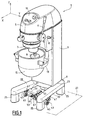
- FIG. 1 there is shown a device 1 for processing food products according to the invention.
- the device consists of a mixer-type device, intended to be used in the field of bakery, or in the field of food preparation for communities.
- the apparatus 1 essentially comprises a body 3, provided with a head 5 which contains an electric motor, and a support 6 on which the body 3 is mounted, and through which the device rests on the ground.
- a tool holder 7 On the head 5 is mounted a tool holder 7, oriented vertically downwards, which is intended to transmit the movement at the motor output to a tool 8.
- the body 3 is provided with a plurality of control members, such as buttons arranged on a control panel 10, and operating levers 11, 12.
- the body 3 is secured to two support arms 13, spaced apart to receive a receptacle 15 in which the tool 8 can be immersed during operation of the apparatus.
- the support 6 essentially comprises two bearing bars 22 extending substantially parallel along the axis X, and spaced transversely.
- the bars 22 are integral with the base 23 of the body 3 at their rear portion.
- the support 6 comprises, at each end of the bars 22, a support foot 25 extending essentially vertically, and resting by its lower face on the bearing surface 27 formed by the ground.
- the apparatus 1 further comprises a rolling mechanism 31, provided to allow the movement of the apparatus 1 by rolling on the ground.
- the mechanism 31 is provided to retract during use of the apparatus, leaving the feet 27 resting on the ground.
- the rolling mechanism 31 is fixed under the two supporting bars 22, on the front side, and on the rear side to the right of the base 23 of the body.
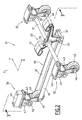
- the mechanism 31 comprises three similar subsets 32, 33 rolling support.
- Each of these subassemblies 32, 33 comprises a mounting plate 41 fixed to the support 6, a wheel clevis 43, and a wheel 45, rotatably mounted about its axis in the yoke 43.
- the axis of rotation of the wheel extends transversely, in the direction Y, and is materialized by a wheel shaft 46.
- the plate 41 has a yoke 47, in which is pivotally mounted the yoke 43, about a transverse tilting axis, parallel to the axis of the wheel 45.
- Two subassemblies 32 are arranged at the front of the mechanism 31, so that the tilting axes of the two corresponding yokes 43 are aligned.
- This common tilting axis is embodied by a shaft 51 secured to each of the two front clevises 43 by means of a pin (not shown) and rotatably mounted in the stirrups 47.
- the other subassembly 33 is arranged at the rear of the mechanism 31, in the vertical median plane of the mechanism 31, so that the latter has a symmetry with respect to this vertical median plane.
- the wheel 45 of the rear subassembly 33 is rotatably mounted in its yoke 43, which is pivotally mounted in its yoke 47.
- the shaft materializing the tilting axis of the yoke in the yoke stirrup is designated by reference 52.
- the axes of rotation of the rear wheel 45 in the yoke 43, on the one hand, and tilting of the yoke 43 in the yoke 47, on the other hand, extend parallel to those of the front subassemblies 32.
- the mechanism further comprises, arranged in the vertical median plane, an operating lever 53 secured to the shaft 51 by means of a pin 55.
- This lever 53 has two distinct pressure-actuated surfaces, defined by two pedals 57, 58.
- the pedals 57, 58 are respectively arranged at the rear and at the front of the shaft 51, so that a pressure exerted on one of the pedals 57, 58 produces a rotation in the opposite direction to that of a rotation produced by pressure on the other pedal.
- the two bearing surfaces are provided on two separate branches of the lever, but they could consist of two areas of the same lever leg, or the same pedal.
- the mechanism 31 further comprises a rigid linkage arm 59, connecting the lever 53 to the yoke 43 of the rear subassembly 33.
- This linkage arm 59 extends along the axis X, and consists essentially of two parallel bars 61.
- the lever 53 is rotatably mounted on the connecting arm 59, in front of the latter, around a transverse shaft 63 connecting the two bars 61.
- the two bars 61 are connected by the shaft 46 of the rear wheel 45, the latter being rotatably mounted between the bars 61 of the link arm.
- the linkage arm 59 further comprises a rod 67 for joining the two bars 61, arranged transversely to the front of the shaft 63, so as to define a stop for rotating the lever 53.
- the plates 41 of the front subassemblies 32 are fixed under the bearing bars 22, towards the front of the latter, so that the pedals 57, 58 are accessible to a user placed in front of the apparatus 1, and that lever 53 is disengaged from support 6.
- the plate 41 of the rear subassembly 33 is fixed under the support 6, to the right of the base of the body 3, as previously mentioned.
- the plates 41 are rigidly connected to each other only via the support 6, that is to say from the moment when the mechanism 31 is mounted on the support 6.
- the mechanism 31 is designed to be able to selectively take one (or) configuration (s) retracted (s), such as shown (s) in Figures 1 to 3, and a rolling configuration, as shown on the Figure 4
- the support legs 25 are on the floor 27, the rollers 45 can also touch the ground, but not ensuring the support of the device.
- the feet are lifted from the ground 27, and the apparatus 1 rests on the ground via the wheels 45 only.
- the yokes are then in a stable position relative to the stirrups, because the axis of rotation of the rollers 45 is at the rear of the tilting axis of the yokes 43.
- the weight of the apparatus tends to tilt the screed in the same clockwise direction, the movement of tilting in this direction being stopped by the stop of the lever 53 on the stop rod 67.
- rolling mechanism which is intended to be fixed permanently under the support of the apparatus, may be optionally mounted on a standard apparatus.
Abstract
Description
La présente invention concerne un dispositif de traitement de produits alimentaires comprenant
- un corps,
- un support, sur lequel est monté le corps et possédant des pieds d'appui au sol, et
- un mécanisme de roulement doté de roulettes, prévu pour permettre le déplacement du dispositif par roulement sur le sol.
- a body,
- a support, on which is mounted the body and having support feet on the ground, and
- a rolling mechanism provided with wheels, provided to allow the device to be rotated on the ground.
L'invention concerne plus particulièrement le domaine des appareils de préparation alimentaire industrielle ou pour collectivités, ces appareils se caractérisant par une taille et un poids relativement importants.The invention relates more particularly to the field of industrial or community food preparation apparatus, these devices being characterized by a relatively large size and weight.
Pour cette raison, ces appareils sont généralement placés à demeure à un emplacement déterminé d'une salle de préparation ou d'une cuisine, et ne sont déplacés qu'occasionnellement. Compte-tenu de la stabilité nécessaire à une utilisation correcte d'un tel appareil, ce dernier est maintenu en appui sur ses pieds lors de son fonctionnement, et le mécanisme de roulement utilisé pour déplacer l'appareil est généralement un chariot distinct sur lequel on place provisoirement l'appareil.For this reason, these devices are usually placed in a fixed location in a preparation room or kitchen, and are moved only occasionally. Given the stability necessary for the correct use of such a device, the latter is maintained in support on its feet during operation, and the rolling mechanism used to move the device is generally a separate carriage on which one place the device temporarily.
Certains appareils multifonctions, prévus pour réaliser différentes opérations dans la chaîne de préparation alimentaire, ont cependant une souplesse d'utilisation limitée par le fait que certaines réglementations en vigueur dans le domaine de la restauration collective interdisent la réalisation de plusieurs opérations de préparation en un même lieu.Some multifunction devices, intended to perform various operations in the food preparation chain, however, have a limited flexibility of use because certain regulations in force in the field of collective catering prohibit the completion of several preparation operations in one and the same location.
Il est donc nécessaire, pour accroître la souplesse d'utilisation de ces appareils, de rendre plus facile leurs déplacements d'un point à un autre de la chaîne de préparation alimentaire.It is therefore necessary, to increase the flexibility of use of these devices, to make their movements easier from one point to another in the food preparation chain.
Il est également souhaitable de rendre plus faciles les déplacements de ces appareils entre leur lieu d'utilisation et des zones de nettoyage ou de stockage, notamment.It is also desirable to make it easier to move these devices between their place of use and cleaning or storage areas, among others.
L'invention a pour but d'atteindre cet objectif sans compromettre la stabilité de l'appareil en utilisation.The invention aims to achieve this goal without compromising the stability of the device in use.
Ce but est atteint par l'invention, qui a pour objet un dispositif du type précité, dans lequel le mécanisme est fixé au support, et adapté pour pouvoir prendre sélectivement une configuration escamotée, dans laquelle les pieds du support portent sur le sol, et une configuration de roulement, dans laquelle les roulettes portent sur le sol tandis que les pieds sont soulevés du sol.This object is achieved by the invention, which relates to a device of the aforementioned type, in which the mechanism is fixed to the support, and adapted to selectively take a retracted configuration, in which the feet of the support bear on the ground, and a rolling configuration, in which the rollers bear on the ground while the feet are raised from the ground.
Suivant d'autres caractéristiques de l'invention, prises seules ou selon toutes les combinaisons techniquement envisageables :
- le mécanisme comprend un levier de manoeuvre, dont l'actionnement permet de passer d'une configuration à une autre ;
- le mécanisme comprend une structure de montage sur laquelle est fixé le support, un train avant et un train arrière de roulettes, chaque roulette étant susceptible de tourner autour de son axe, et de basculer autour d'un axe parallèle sous l'effet de l'actionnement du levier de manoeuvre, entre une position escamotée et une position portante ;
- le mécanisme comprend un bras de liaison permettant de lier le basculement des roulettes du train avant et du train arrière ;
- chaque roulette est montée rotative autour de son axe dans une chape en U, laquelle est montée basculante sur la structure ;
- les roulettes du train avant ont un axe de basculement commun, matérialisé par un arbre, solidaire du levier de manoeuvre et des chapes des roulettes du train avant ;
- le levier de manoeuvre est articulé en rotation sur le bras de liaison autour d'un axe parallèle audit arbre, et arrêté en rotation dans la position portante des roulettes au moyen d'une butée solidaire du bras de liaison ;
- le train avant comporte deux roulettes espacées transversalement ;
- le levier de manoeuvre est agencé entre les deux roulettes du train avant ;
- le train arrière comprend une roulette unique ;
- la structure de montage comprend une pluralité de platines sur lesquelles est fixé le support, et sur chaque platine est montée une roulette respective, les platines constituant ensemble une structure déformable ; et
- le levier de manoeuvre comprend deux surfaces d'appui prévues chacune pour assurer, lorsqu'elle est pressée, un basculement du levier dans l'un respective des deux sens opposés, correspondant au passage des roulettes de l'une à l'autre de leur position escamotée et de leur position portante.
- the mechanism comprises an operating lever, the actuation of which moves from one configuration to another;
- the mechanism comprises a mounting structure on which is fixed the support, a front axle and a rear wheel set, each wheel being able to rotate about its axis, and to tilt about a parallel axis under the effect of the actuating the operating lever, between a retracted position and a bearing position;
- the mechanism comprises a link arm for linking the tilting of the casters of the front axle and the rear axle;
- each wheel is rotatably mounted about its axis in a U-shaped yoke, which is pivotally mounted on the structure;
- the wheels of the front axle have a common tilting axis, materialized by a shaft, integral with the operating lever and clevis wheels of the front axle;
- the operating lever is articulated in rotation on the connecting arm about an axis parallel to said shaft, and stopped in rotation in the bearing position of the rollers by means of an abutment integral with the connecting arm;
- the front axle comprises two casters spaced transversely;
- the operating lever is arranged between the two wheels of the front axle;
- the rear axle includes a single wheel;
- the mounting structure comprises a plurality of plates on which the support is fixed, and on each plate is mounted a respective wheel, the plates together forming a deformable structure; and
- the operating lever comprises two support surfaces each provided to ensure, when pressed, a tilting of the lever in a respective one of the two opposite directions, corresponding to the passage of the wheels from one to the other of their retracted position and their bearing position.
Un mode particulier de réalisation de l'invention va maintenant être décrit en référence aux dessins annexés, sur lesquels :
- la Figure 1 est une vue en perspective d'un dispositif selon l'invention ;
- la Figure 2 est une vue en perspective, à plus grande échelle, du mécanisme de roulement du dispositif de la Figure 1, seul;
- la Figure 3 est une vue en coupe dans un plan médian vertical, suivant la direction 3-3, du mécanisme de la Figure 2 en configuration escamotée ; et
- la Figure 4 est une vue analogue à la Figure 3, en configuration de roulement.
- Figure 1 is a perspective view of a device according to the invention;
- Figure 2 is a perspective view, on a larger scale, of the rolling mechanism of the device of Figure 1, alone;
- Figure 3 is a sectional view in a vertical median plane, in the direction 3-3, of the mechanism of Figure 2 in a retracted configuration; and
- Figure 4 is a view similar to Figure 3, in rolling configuration.
Sur la Figure 1, on a représenté un dispositif 1 de traitement de produits alimentaires selon l'invention. Dans l'exemple représenté, le dispositif est constitué d'un appareil du type batteur-mélangeur, prévu pour être utilisé dans le domaine de la boulangerie-pâtisserie, ou dans la domaine de la préparation alimentaire pour collectivités.In Figure 1, there is shown a
Bien entendu, l'invention pourrait être illustrée avec d'autres types d'appareils, tels que des éplucheuses, des trancheuses, ou encore des mixeurs.Of course, the invention could be illustrated with other types of apparatus, such as peelers, slicers, or mixers.
Dans la partie de description faite en référence à la Figure 1, l'appareil sera supposé être dans sa position d'utilisation, en appui sur le sol, telle que représentée.In the description part made with reference to FIG. 1, the apparatus will be assumed to be in its position of use, resting on the ground, as shown.
L'appareil 1 est orienté suivant un système d'axes X, Y, Z, dans lequel :
- l'axe X est l'axe horizontal, orienté de l'appareil vers l'emplacement prévu pour l'utilisateur, cette orientation étant supposée d'arrière en avant ;
- l'axe Y est l'axe horizontal transversal ; et
- l'axe Z est l'axe vertical orienté du bas vers le haut.
- the X axis is the horizontal axis, oriented from the device to the location provided for the user, this orientation being assumed from back to front;
- the Y axis is the transverse horizontal axis; and
- the Z axis is the vertical axis oriented from bottom to top.
Tous les termes de direction et de position s'entendront par rapport à ce système d'axes.All direction and position terms will be related to this axis system.
Comme cela est visible sur la Figure 1, l'appareil 1 comporte essentiellement un corps 3, doté d'une tête 5 qui contient un moteur électrique, et un support 6, sur lequel est monté le corps 3, et par l'intermédiaire duquel l'appareil repose sur le sol.As can be seen in FIG. 1, the
Sur la tête 5 est monté un porte-outils 7, orienté verticalement vers le bas, qui est destiné à transmettre le mouvement en sortie de moteur à un outil 8.On the
Le corps 3 est pourvu d'une pluralité d'organes de commande, tels que des boutons agencés sur un panneau de commande 10, et des leviers de manoeuvre 11, 12.The body 3 is provided with a plurality of control members, such as buttons arranged on a
Le corps 3 est solidaire de deux bras de support 13, espacés pour recevoir en appui un récipient 15, dans lequel peut être plongé l'outil 8, en fonctionnement de l'appareil.The body 3 is secured to two
Dans l'exemple représenté, le support 6 comporte essentiellement deux barres portantes 22 s'étendant sensiblement parallèlement suivant l'axe X, et espacées transversalement. Les barres 22 sont solidaires de la base 23 du corps 3 au niveau de leur partie arrière.In the example shown, the
Le support 6 comporte, à chaque extrémité des barres 22, un pied d'appui 25 s'étendant essentiellement de façon verticale, et reposant par sa face inférieure sur la surface d'appui 27 constituée par le sol.The
L'appareil 1 comprend en outre un mécanisme de roulement 31, prévu pour permettre le déplacement de l'appareil 1 par roulement sur le sol. Le mécanisme 31 est prévu pour s'escamoter lors de l'utilisation de l'appareil, en laissant les pieds 27 en appui sur le sol.The
Le mécanisme de roulement 31 est fixé sous les deux barres portantes 22, du côté avant, et du côté arrière au droit de la base 23 du corps.The rolling
Le mécanisme 31 va maintenant être décrit plus en détail en référence aux Figures 2 à 4.The
Le mécanisme 31 comprend trois sous-ensembles analogues 32, 33 de support roulant.The
Chacun de ces sous-ensembles 32, 33 comprend une platine de montage 41 fixée au support 6, une chape de roue 43, et une roulette 45, montée rotative autour de son axe dans la chape 43. L'axe de rotation de la roulette s'étend transversalement, selon la direction Y, et est matérialisé par un arbre de roulette 46.Each of these
La platine 41 présente un étrier 47, dans lequel est montée pivotante la chape 43, autour d'un axe de basculement transversal, parallèle à l'axe de la roulette 45.The
Deux sous-ensembles 32 sont disposés à l'avant du mécanisme 31, de façon que les axes de basculement des deux chapes 43 correspondantes soient alignés. Cet axe de basculement commun est matérialisé par un arbre 51, solidaire de chacune des deux chapes avant 43 au moyen d'une goupille (non représentée), et monté libre en rotation dans les étriers 47.Two
L'autre sous-ensemble 33 est agencé à l'arrière du mécanisme 31, dans le plan médian vertical du mécanisme 31, de sorte que ce dernier présente une symétrie par rapport à ce plan médian vertical.The
De façon analogue aux sous-ensembles avant 32, la roulette 45 du sous-ensemble arrière 33 est montée rotative dans sa chape 43, laquelle est montée pivotante dans son étrier 47. L'arbre matérialisant l'axe de basculement de la chape dans l'étrier est désigné par la référence 52.Similarly to the
Les axes de rotation de la roulette arrière 45 dans la chape 43, d'une part, et de basculement de la chape 43 dans l'étrier 47, d'autre part, s'étendent parallèlement à ceux des sous-ensembles avant 32.The axes of rotation of the
Le mécanisme comprend en outre, agencé dans le plan médian vertical, un levier de manoeuvre 53 solidarisé à l'arbre 51 au moyen d'une goupille 55.The mechanism further comprises, arranged in the vertical median plane, an operating
Ce levier 53 présente deux surfaces distinctes d'actionnement par pression, définies par deux pédales 57, 58. Les pédales 57, 58 sont agencées respectivement à l'arrière et à l'avant de l'arbre 51, de sorte qu'une pression exercée sur l'une des pédales 57, 58 produit une rotation en sens opposé à celui d'une rotation produite par pression sur l'autre pédale.This
Dans l'exemple représenté, les deux surfaces d'appui sont prévues sur deux branches distinctes du levier, mais elles pourraient être constituées de deux zones d'une même branche de levier, ou d'une même pédale.In the example shown, the two bearing surfaces are provided on two separate branches of the lever, but they could consist of two areas of the same lever leg, or the same pedal.
Le mécanisme 31 comprend en outre un bras de liaison rigide 59, reliant le levier 53 à la chape 43 du sous-ensemble arrière 33. Ce bras de liaison 59 s'étend selon l'axe X, et est constitué essentiellement de deux barres parallèles 61.The
Le levier 53 est monté rotatif sur le bras de liaison 59, à l'avant de ce dernier, autour d'un arbre transversal 63 reliant les deux barres 61.The
Du côté opposé du bras de liaison 59, les deux barres 61 sont reliées par l'arbre 46 de la roulette arrière 45, cette dernière étant ainsi montée rotative entre les barres 61 du bras de liaison.On the opposite side of the connecting
Le bras de liaison 59 comprend en outre une tige 67 de jonction des deux barres 61, agencée transversalement à l'avant de l'arbre 63, de façon à définir une butée d'arrêt en rotation pour le levier 53.The
Comme cela apparaît sur la Figure 1, les platines 41 des sous-ensembles avant 32 sont fixées sous les barres portantes 22, vers l'avant de ces dernières, de façon que les pédales 57, 58 soient accessibles pour un utilisateur placé devant l'appareil 1, et que le levier 53 soit dégagé du support 6.As shown in Figure 1, the
La platine 41 du sous-ensemble arrière 33 est, elle, fixée sous le support 6, au droit de la base du corps 3, comme cela a été évoqué précédemment.The
Les platines 41 des trois sous-ensembles 32, 33 définissent ensemble une structure de montage, qui est déformable avant montage du mécanisme 31 sur le support 6, puisque les platines ne sont alors pas reliées rigidement les unes aux autres. Les platines 41 ne sont rigidement liées entre elles que par l'intermédiaire du support 6, c'est-à-dire à partir du moment où le mécanisme 31 est monté sur le support 6.The
Le mécanisme 31 est conçu pour pouvoir prendre sélectivement une (ou des) configuration(s) escamotée(s), telle(s) que représentée(s) sur les Figures 1 à 3, et une configuration de roulement, telle que représentée sur la Figure 4.The
Dans la (ou les) configuration(s) escamotée(s), les pieds de support 25 portent sur le sol 27, les roulettes 45 pouvant également toucher le sol, mais n'assurant pas le support de l'appareil.In the (or) configuration (s) retracted (s), the
Dans la configuration de roulement, les pieds sont soulevés du sol 27, et l'appareil 1 repose sur le sol par l'intermédiaire des roulettes 45 uniquement.In the rolling configuration, the feet are lifted from the
A partir de la position escamotée représentée sur la Figure 3, une pression sur la pédale 58 située à l'avant de l'arbre 51 entraîne un basculement des chapes avant 43 dans le sens horaire (selon la direction d'observation de la Figure 3), solidairement avec la rotation de l'arbre 51. Ce même mouvement de basculement est transmis à la chape arrière 43 par l'intermédiaire du bras de liaison 59, ce dernier subissant un recul sensiblement suivant son axe.From the retracted position shown in FIG. 3, a pressure on the pedal 58 situated at the front of the
Le basculement des chapes 43 fait passer les arbres de roulette 46 à l'arrière des arbres respectifs 51, 52 de basculement, jusqu'à la position de blocage, définie par la venue en butée du levier 53 sur la tige d'arrêt 67. Cette position est illustrée sur la Figure 4.The tilting of the
Dans cette position de blocage des chapes 43 dans leurs étriers 47 respectifs, les roulettes 45 sont portantes.In this locking position of the
Les chapes sont alors dans une position stable par rapport aux étriers, du fait que l'axe de rotation des roulettes 45 soit à l'arrière de l'axe de basculement des chapes 43. Le poids de l'appareil tend à faire basculer les chapes dans le même sens horaire, le mouvement de basculement dans ce sens étant arrêté par la butée du levier 53 sur la tige d'arrêt 67.The yokes are then in a stable position relative to the stirrups, because the axis of rotation of the
On comprend que, de façon inverse, pour faire passer le mécanisme 31 de sa configuration de roulement (Figure 4) à sa configuration escamotée (Figure 3), il est nécessaire d'appliquer une pression sur la pédale arrière 57. Une telle pression produit dans un premier temps le soulèvement de l'appareil 1 sur les roulettes, puis, après passage de l'axe de rotation des roulettes 45 au droit de l'axe de basculement des chapes 43, une redescente de l'appareil jusqu'à l'appui des pieds 25 au sol.It is understood that, inversely, to move the
Aucune butée d'arrêt pour le levier 53 n'est nécessaire dans ce sens de pivotement, puisqu'après venue en appui des pieds 25, les chapes 43 ne sont plus sollicitées en basculement par le poids de l'appareil. Les roulettes 45 sont alors libres de venir en contact avec le sol, mais n'assurent plus le support de l'appareil.No stop stop for the
Un avantage important de l'invention est que le mécanisme de roulement, qui est destiné à être fixé à demeure sous le support de l'appareil, peut être monté de façon optionnelle sur un appareil standard.An important advantage of the invention is that the rolling mechanism, which is intended to be fixed permanently under the support of the apparatus, may be optionally mounted on a standard apparatus.
Claims (10)
en ce que le mécanisme (31) comprend un levier de manoeuvre (53), dont l'actionnement permet de passer d'une configuration à une autre, et
en ce que le mécanisme (31) comprend une structure de montage (41) sur laquelle est fixé le support (6), un train avant et un train arrière de roulettes, chaque roulette (45) étant susceptible de tourner autour de son axe, et de basculer autour d'un axe parallèle sous l'effet de l'actionnement du levier de manoeuvre (53), entre une position escamotée et une position portante.Food processing device comprising
in that the mechanism (31) comprises an operating lever (53), the actuation of which makes it possible to switch from one configuration to another, and
in that the mechanism (31) comprises a mounting structure (41) on which is fixed the support (6), a front axle and a rear wheel set, each wheel (45) being rotatable about its axis, and tilt about a parallel axis under the effect of actuating the operating lever (53) between a retracted position and a bearing position.
caractérisé en ce que le mécanisme (31) comprend un bras de liaison (59) permettant de lier le basculement des roulettes (45) du train avant et du train arrière.Device according to claim 1,
characterized in that the mechanism (31) comprises a connecting arm (59) for linking the tilting of the rollers (45) of the front axle and the rear axle.
caractérisé en ce que chaque roulette (45) est montée rotative autour de son axe dans une chape en U (43), laquelle est montée basculante sur la structure (41).Device according to Claim 1 or 2,
characterized in that each roller (45) is rotatably mounted about its axis in a U-shaped yoke (43), which is pivotally mounted on the structure (41).
caractérisé en ce que les roulettes (45) du train avant ont un axe de basculement commun, matérialisé par un arbre (51), solidaire du levier de manoeuvre (53) et des chapes (43) des roulettes (45) du train avant.Device according to Claim 3,
characterized in that the wheels (45) of the front axle have a common tilting axis, embodied by a shaft (51) integral with the operating lever (53) and clevises (43) of the wheels (45) of the front axle.
caractérisé en ce que le levier de manoeuvre (53) est articulé en rotation sur le bras de liaison (59) autour d'un axe (63) parallèle audit arbre (51), et arrêté en rotation dans la position portante des roulettes (45) au moyen d'une butée (67) solidaire du bras de liaison (59).Device according to Claim 4,
characterized in that the operating lever (53) is articulated in rotation on the link arm (59) about an axis (63) parallel to said shaft (51), and stopped in rotation in the bearing position of the rollers (45). ) by means of a stop (67) integral with the connecting arm (59).
caractérisé en ce que le levier de manoeuvre (53) est agencé entre les deux roulettes (45) du train avant.Device according to Claim 6,
characterized in that the operating lever (53) is arranged between the two wheels (45) of the front axle.
caractérisé en ce que le train arrière comprend une roulette (45) unique.Device according to Claim 6 or 7,
characterized in that the rear axle comprises a single wheel (45).
Applications Claiming Priority (1)
| Application Number | Priority Date | Filing Date | Title |
|---|---|---|---|
| FR0411305A FR2876893B1 (en) | 2004-10-22 | 2004-10-22 | PROCESSING DEVICE FOR FOOD PRODUCTS MOUNTED ON WHEELS |
Publications (2)
| Publication Number | Publication Date |
|---|---|
| EP1650100A1 true EP1650100A1 (en) | 2006-04-26 |
| EP1650100B1 EP1650100B1 (en) | 2007-07-11 |
Family
ID=34949979
Family Applications (1)
| Application Number | Title | Priority Date | Filing Date |
|---|---|---|---|
| EP05292207A Not-in-force EP1650100B1 (en) | 2004-10-22 | 2005-10-20 | Apparatus for the treatment of food products mounted on wheels |
Country Status (6)
| Country | Link |
|---|---|
| EP (1) | EP1650100B1 (en) |
| AT (1) | ATE366688T1 (en) |
| DE (1) | DE602005001598T2 (en) |
| DK (1) | DK1650100T3 (en) |
| ES (1) | ES2289672T3 (en) |
| FR (1) | FR2876893B1 (en) |
Cited By (1)
| Publication number | Priority date | Publication date | Assignee | Title |
|---|---|---|---|---|
| FR2985420A1 (en) * | 2012-01-09 | 2013-07-12 | Denis Jean Montbabut | Device for assisting person having reduced mobility and moving with walker or English cane in old people home, has steel pedal fixed by nut on tube between rear legs of chair, where large wheel is fixed on steel pedal by nuts |
Citations (5)
| Publication number | Priority date | Publication date | Assignee | Title |
|---|---|---|---|---|
| US3422929A (en) * | 1967-07-31 | 1969-01-21 | Carl W Oja | Floor contacting brake mechanism |
| US4846493A (en) * | 1987-10-26 | 1989-07-11 | Mason Donald W | Portable cooler with retractable wheels |
| DE10108562A1 (en) * | 2001-02-22 | 2002-09-12 | Apollinaris Brunnen Ag | Multi-functional food and drink serving trolley, comprising various storage facilities and snack preparation area |
| DE10126962A1 (en) * | 2001-03-15 | 2002-10-02 | Helmut Plagge | Mobility device for movable object has wheel element able to rotate and/or move so that wheel axle of wheel element can be moved by pressure applied to wheel element |
| US20020144846A1 (en) * | 2001-02-20 | 2002-10-10 | Darby Kenneth S. | Device to move an occupied chair |
-
2004
- 2004-10-22 FR FR0411305A patent/FR2876893B1/en not_active Expired - Fee Related
-
2005
- 2005-10-20 ES ES05292207T patent/ES2289672T3/en active Active
- 2005-10-20 DK DK05292207T patent/DK1650100T3/en active
- 2005-10-20 AT AT05292207T patent/ATE366688T1/en not_active IP Right Cessation
- 2005-10-20 EP EP05292207A patent/EP1650100B1/en not_active Not-in-force
- 2005-10-20 DE DE602005001598T patent/DE602005001598T2/en active Active
Patent Citations (5)
| Publication number | Priority date | Publication date | Assignee | Title |
|---|---|---|---|---|
| US3422929A (en) * | 1967-07-31 | 1969-01-21 | Carl W Oja | Floor contacting brake mechanism |
| US4846493A (en) * | 1987-10-26 | 1989-07-11 | Mason Donald W | Portable cooler with retractable wheels |
| US20020144846A1 (en) * | 2001-02-20 | 2002-10-10 | Darby Kenneth S. | Device to move an occupied chair |
| DE10108562A1 (en) * | 2001-02-22 | 2002-09-12 | Apollinaris Brunnen Ag | Multi-functional food and drink serving trolley, comprising various storage facilities and snack preparation area |
| DE10126962A1 (en) * | 2001-03-15 | 2002-10-02 | Helmut Plagge | Mobility device for movable object has wheel element able to rotate and/or move so that wheel axle of wheel element can be moved by pressure applied to wheel element |
Cited By (1)
| Publication number | Priority date | Publication date | Assignee | Title |
|---|---|---|---|---|
| FR2985420A1 (en) * | 2012-01-09 | 2013-07-12 | Denis Jean Montbabut | Device for assisting person having reduced mobility and moving with walker or English cane in old people home, has steel pedal fixed by nut on tube between rear legs of chair, where large wheel is fixed on steel pedal by nuts |
Also Published As
| Publication number | Publication date |
|---|---|
| FR2876893A1 (en) | 2006-04-28 |
| DE602005001598T2 (en) | 2008-04-03 |
| ES2289672T3 (en) | 2008-02-01 |
| FR2876893B1 (en) | 2008-04-18 |
| DE602005001598D1 (en) | 2007-08-23 |
| ATE366688T1 (en) | 2007-08-15 |
| EP1650100B1 (en) | 2007-07-11 |
| DK1650100T3 (en) | 2007-11-05 |
Similar Documents
| Publication | Publication Date | Title |
|---|---|---|
| EP0511113B1 (en) | Personal vehicle usable in a handpropelled or motorised mode, especially a wheelchair or tricycle | |
| FR2541204A1 (en) | ARTICULATED SEAT, ESPECIALLY FOR TRUCKS AND BUSES | |
| FR2561099A1 (en) | IMPROVED HOSPITAL BED | |
| FR2492657A1 (en) | Wheelchair for handicapped person - has articulated seat and back sections with jack tilting seat to vertical position to help user to stand | |
| EP1650100B1 (en) | Apparatus for the treatment of food products mounted on wheels | |
| FR2740652A1 (en) | HAYING MACHINE WITH AT LEAST ONE SWATCHING ROTOR AND ENABLING IN PARTICULAR BETTER ADAPTATION OF THE ROTOR TO THE GROUND SURFACE | |
| EP3079545B1 (en) | Household food preparation appliance comprising a base, a lower arm and an upper arm pivotably mounted on the lower arm | |
| EP2915454B1 (en) | Furniture equipped with displacement means | |
| WO2021152228A1 (en) | Wheelchair | |
| WO1997035060A1 (en) | Ironing press | |
| EP2762121B1 (en) | Stand-up wheelchair for disabled persons | |
| FR2887143A1 (en) | Manual or electric wheelchair for mobility impaired person, has roller placed higher so that supports and roller pivot towards front during blocking of another roller till former roller contacts ground to permit wheelchair to cross obstacle | |
| FR3014669A1 (en) | CULINARY PREPARATION ELECTRICAL APPLIANCE COMPRISING A LOWER ARM CARRIED BY A BASE AND AN UPPER ARM CONNECTED TO THE LOWER ARM BY A JOINT DEVICE | |
| FR3019019A1 (en) | BODY-HOLDING DEVICE IN STAND-UP POSITION OR SITTING-STANDING OR SITTING | |
| FR2704740A1 (en) | Nozzle for dust vacuum cleaner. | |
| EP0047210A1 (en) | Retractable caster assembly, and appliances equipped with it | |
| EP0060798A1 (en) | Muscle exercise apparatus | |
| WO2019180654A1 (en) | Device for helping the transition from a seated position to a standing position, and vice versa, mobility platform for seat comprising such a device, and wheelchair | |
| EP0113635A1 (en) | Apparatus for displacing handicapped persons | |
| BE681213A (en) | ||
| EP4344591A1 (en) | Cooking appliance with rotatable grip handle | |
| EP0722849B1 (en) | Castor with adjustable locking of steering | |
| EP4355682A1 (en) | Control console for a personnel-lifting machine, and personnel-lifting machine comprising such a control console | |
| EP0274312A2 (en) | Re-education apparatus for the recuperation and exercising of the mobility of the pelvis | |
| FR2641664A1 (en) | Apparatus for working the ground, particularly for forestry work |
Legal Events
| Date | Code | Title | Description |
|---|---|---|---|
| PUAI | Public reference made under article 153(3) epc to a published international application that has entered the european phase |
Free format text: ORIGINAL CODE: 0009012 |
|
| AK | Designated contracting states |
Kind code of ref document: A1 Designated state(s): AT BE BG CH CY CZ DE DK EE ES FI FR GB GR HU IE IS IT LI LT LU LV MC NL PL PT RO SE SI SK TR |
|
| AX | Request for extension of the european patent |
Extension state: AL BA HR MK YU |
|
| 17P | Request for examination filed |
Effective date: 20060928 |
|
| AKX | Designation fees paid |
Designated state(s): AT BE BG CH CY CZ DE DK EE ES FI FR GB GR HU IE IS IT LI LT LU LV MC NL PL PT RO SE SI SK TR |
|
| GRAP | Despatch of communication of intention to grant a patent |
Free format text: ORIGINAL CODE: EPIDOSNIGR1 |
|
| GRAS | Grant fee paid |
Free format text: ORIGINAL CODE: EPIDOSNIGR3 |
|
| GRAA | (expected) grant |
Free format text: ORIGINAL CODE: 0009210 |
|
| AK | Designated contracting states |
Kind code of ref document: B1 Designated state(s): AT BE BG CH CY CZ DE DK EE ES FI FR GB GR HU IE IS IT LI LT LU LV MC NL PL PT RO SE SI SK TR |
|
| REG | Reference to a national code |
Ref country code: GB Ref legal event code: FG4D Free format text: NOT ENGLISH |
|
| REG | Reference to a national code |
Ref country code: CH Ref legal event code: EP |
|
| GBT | Gb: translation of ep patent filed (gb section 77(6)(a)/1977) |
Effective date: 20070719 |
|
| REF | Corresponds to: |
Ref document number: 602005001598 Country of ref document: DE Date of ref document: 20070823 Kind code of ref document: P |
|
| REG | Reference to a national code |
Ref country code: IE Ref legal event code: FG4D Free format text: LANGUAGE OF EP DOCUMENT: FRENCH |
|
| REG | Reference to a national code |
Ref country code: SE Ref legal event code: TRGR |
|
| REG | Reference to a national code |
Ref country code: DK Ref legal event code: T3 |
|
| PG25 | Lapsed in a contracting state [announced via postgrant information from national office to epo] |
Ref country code: LT Free format text: LAPSE BECAUSE OF FAILURE TO SUBMIT A TRANSLATION OF THE DESCRIPTION OR TO PAY THE FEE WITHIN THE PRESCRIBED TIME-LIMIT Effective date: 20070711 Ref country code: PT Free format text: LAPSE BECAUSE OF FAILURE TO SUBMIT A TRANSLATION OF THE DESCRIPTION OR TO PAY THE FEE WITHIN THE PRESCRIBED TIME-LIMIT Effective date: 20071211 Ref country code: IS Free format text: LAPSE BECAUSE OF FAILURE TO SUBMIT A TRANSLATION OF THE DESCRIPTION OR TO PAY THE FEE WITHIN THE PRESCRIBED TIME-LIMIT Effective date: 20071111 Ref country code: FI Free format text: LAPSE BECAUSE OF FAILURE TO SUBMIT A TRANSLATION OF THE DESCRIPTION OR TO PAY THE FEE WITHIN THE PRESCRIBED TIME-LIMIT Effective date: 20070711 Ref country code: NL Free format text: LAPSE BECAUSE OF FAILURE TO SUBMIT A TRANSLATION OF THE DESCRIPTION OR TO PAY THE FEE WITHIN THE PRESCRIBED TIME-LIMIT Effective date: 20070711 Ref country code: BG Free format text: LAPSE BECAUSE OF FAILURE TO SUBMIT A TRANSLATION OF THE DESCRIPTION OR TO PAY THE FEE WITHIN THE PRESCRIBED TIME-LIMIT Effective date: 20071011 |
|
| NLV1 | Nl: lapsed or annulled due to failure to fulfill the requirements of art. 29p and 29m of the patents act | ||
| REG | Reference to a national code |
Ref country code: ES Ref legal event code: FG2A Ref document number: 2289672 Country of ref document: ES Kind code of ref document: T3 |
|
| PG25 | Lapsed in a contracting state [announced via postgrant information from national office to epo] |
Ref country code: AT Free format text: LAPSE BECAUSE OF FAILURE TO SUBMIT A TRANSLATION OF THE DESCRIPTION OR TO PAY THE FEE WITHIN THE PRESCRIBED TIME-LIMIT Effective date: 20070711 Ref country code: PL Free format text: LAPSE BECAUSE OF FAILURE TO SUBMIT A TRANSLATION OF THE DESCRIPTION OR TO PAY THE FEE WITHIN THE PRESCRIBED TIME-LIMIT Effective date: 20070711 |
|
| REG | Reference to a national code |
Ref country code: IE Ref legal event code: FD4D |
|
| PG25 | Lapsed in a contracting state [announced via postgrant information from national office to epo] |
Ref country code: LV Free format text: LAPSE BECAUSE OF FAILURE TO SUBMIT A TRANSLATION OF THE DESCRIPTION OR TO PAY THE FEE WITHIN THE PRESCRIBED TIME-LIMIT Effective date: 20070711 |
|
| BERE | Be: lapsed |
Owner name: ELECTROLUX PROFESSIONNEL Effective date: 20071031 |
|
| PG25 | Lapsed in a contracting state [announced via postgrant information from national office to epo] |
Ref country code: GR Free format text: LAPSE BECAUSE OF FAILURE TO SUBMIT A TRANSLATION OF THE DESCRIPTION OR TO PAY THE FEE WITHIN THE PRESCRIBED TIME-LIMIT Effective date: 20071012 |
|
| PLBE | No opposition filed within time limit |
Free format text: ORIGINAL CODE: 0009261 |
|
| STAA | Information on the status of an ep patent application or granted ep patent |
Free format text: STATUS: NO OPPOSITION FILED WITHIN TIME LIMIT |
|
| PG25 | Lapsed in a contracting state [announced via postgrant information from national office to epo] |
Ref country code: SK Free format text: LAPSE BECAUSE OF FAILURE TO SUBMIT A TRANSLATION OF THE DESCRIPTION OR TO PAY THE FEE WITHIN THE PRESCRIBED TIME-LIMIT Effective date: 20070711 Ref country code: MC Free format text: LAPSE BECAUSE OF NON-PAYMENT OF DUE FEES Effective date: 20071031 Ref country code: CZ Free format text: LAPSE BECAUSE OF FAILURE TO SUBMIT A TRANSLATION OF THE DESCRIPTION OR TO PAY THE FEE WITHIN THE PRESCRIBED TIME-LIMIT Effective date: 20070711 Ref country code: IE Free format text: LAPSE BECAUSE OF FAILURE TO SUBMIT A TRANSLATION OF THE DESCRIPTION OR TO PAY THE FEE WITHIN THE PRESCRIBED TIME-LIMIT Effective date: 20070711 |
|
| 26N | No opposition filed |
Effective date: 20080414 |
|
| PG25 | Lapsed in a contracting state [announced via postgrant information from national office to epo] |
Ref country code: RO Free format text: LAPSE BECAUSE OF FAILURE TO SUBMIT A TRANSLATION OF THE DESCRIPTION OR TO PAY THE FEE WITHIN THE PRESCRIBED TIME-LIMIT Effective date: 20070711 |
|
| PG25 | Lapsed in a contracting state [announced via postgrant information from national office to epo] |
Ref country code: BE Free format text: LAPSE BECAUSE OF NON-PAYMENT OF DUE FEES Effective date: 20071031 |
|
| PG25 | Lapsed in a contracting state [announced via postgrant information from national office to epo] |
Ref country code: EE Free format text: LAPSE BECAUSE OF FAILURE TO SUBMIT A TRANSLATION OF THE DESCRIPTION OR TO PAY THE FEE WITHIN THE PRESCRIBED TIME-LIMIT Effective date: 20070711 |
|
| PG25 | Lapsed in a contracting state [announced via postgrant information from national office to epo] |
Ref country code: SI Free format text: LAPSE BECAUSE OF FAILURE TO SUBMIT A TRANSLATION OF THE DESCRIPTION OR TO PAY THE FEE WITHIN THE PRESCRIBED TIME-LIMIT Effective date: 20070711 |
|
| PG25 | Lapsed in a contracting state [announced via postgrant information from national office to epo] |
Ref country code: CY Free format text: LAPSE BECAUSE OF FAILURE TO SUBMIT A TRANSLATION OF THE DESCRIPTION OR TO PAY THE FEE WITHIN THE PRESCRIBED TIME-LIMIT Effective date: 20070711 |
|
| PG25 | Lapsed in a contracting state [announced via postgrant information from national office to epo] |
Ref country code: LU Free format text: LAPSE BECAUSE OF NON-PAYMENT OF DUE FEES Effective date: 20071020 |
|
| PG25 | Lapsed in a contracting state [announced via postgrant information from national office to epo] |
Ref country code: HU Free format text: LAPSE BECAUSE OF FAILURE TO SUBMIT A TRANSLATION OF THE DESCRIPTION OR TO PAY THE FEE WITHIN THE PRESCRIBED TIME-LIMIT Effective date: 20080112 Ref country code: TR Free format text: LAPSE BECAUSE OF FAILURE TO SUBMIT A TRANSLATION OF THE DESCRIPTION OR TO PAY THE FEE WITHIN THE PRESCRIBED TIME-LIMIT Effective date: 20070711 |
|
| REG | Reference to a national code |
Ref country code: CH Ref legal event code: PL |
|
| REG | Reference to a national code |
Ref country code: CH Ref legal event code: AEN Free format text: LE BREVET A ETE REACTIVE SELON LA DEMANDE DE LA POURSUITE DE LA PROCEDURE DU 09.07.2010. |
|
| PG25 | Lapsed in a contracting state [announced via postgrant information from national office to epo] |
Ref country code: LI Free format text: LAPSE BECAUSE OF NON-PAYMENT OF DUE FEES Effective date: 20091031 |
|
| PGFP | Annual fee paid to national office [announced via postgrant information from national office to epo] |
Ref country code: CH Payment date: 20100714 Year of fee payment: 5 |
|
| PGRI | Patent reinstated in contracting state [announced from national office to epo] |
Ref country code: CH Effective date: 20100709 |
|
| REG | Reference to a national code |
Ref country code: CH Ref legal event code: PL |
|
| PG25 | Lapsed in a contracting state [announced via postgrant information from national office to epo] |
Ref country code: LI Free format text: LAPSE BECAUSE OF NON-PAYMENT OF DUE FEES Effective date: 20101031 Ref country code: CH Free format text: LAPSE BECAUSE OF NON-PAYMENT OF DUE FEES Effective date: 20101031 |
|
| PGFP | Annual fee paid to national office [announced via postgrant information from national office to epo] |
Ref country code: DK Payment date: 20141022 Year of fee payment: 10 |
|
| PGFP | Annual fee paid to national office [announced via postgrant information from national office to epo] |
Ref country code: DE Payment date: 20141022 Year of fee payment: 10 Ref country code: ES Payment date: 20141028 Year of fee payment: 10 Ref country code: FR Payment date: 20141022 Year of fee payment: 10 |
|
| REG | Reference to a national code |
Ref country code: DE Ref legal event code: R119 Ref document number: 602005001598 Country of ref document: DE |
|
| REG | Reference to a national code |
Ref country code: DK Ref legal event code: EBP Effective date: 20151031 |
|
| PG25 | Lapsed in a contracting state [announced via postgrant information from national office to epo] |
Ref country code: DE Free format text: LAPSE BECAUSE OF NON-PAYMENT OF DUE FEES Effective date: 20160503 |
|
| REG | Reference to a national code |
Ref country code: FR Ref legal event code: ST Effective date: 20160630 |
|
| PG25 | Lapsed in a contracting state [announced via postgrant information from national office to epo] |
Ref country code: FR Free format text: LAPSE BECAUSE OF NON-PAYMENT OF DUE FEES Effective date: 20151102 |
|
| PG25 | Lapsed in a contracting state [announced via postgrant information from national office to epo] |
Ref country code: DK Free format text: LAPSE BECAUSE OF NON-PAYMENT OF DUE FEES Effective date: 20151031 |
|
| REG | Reference to a national code |
Ref country code: ES Ref legal event code: FD2A Effective date: 20161128 |
|
| PG25 | Lapsed in a contracting state [announced via postgrant information from national office to epo] |
Ref country code: ES Free format text: LAPSE BECAUSE OF NON-PAYMENT OF DUE FEES Effective date: 20151021 |
|
| PGFP | Annual fee paid to national office [announced via postgrant information from national office to epo] |
Ref country code: GB Payment date: 20171019 Year of fee payment: 13 Ref country code: IT Payment date: 20171023 Year of fee payment: 13 |
|
| GBPC | Gb: european patent ceased through non-payment of renewal fee |
Effective date: 20181020 |
|
| PG25 | Lapsed in a contracting state [announced via postgrant information from national office to epo] |
Ref country code: IT Free format text: LAPSE BECAUSE OF NON-PAYMENT OF DUE FEES Effective date: 20181020 Ref country code: GB Free format text: LAPSE BECAUSE OF NON-PAYMENT OF DUE FEES Effective date: 20181020 |
|
| PGFP | Annual fee paid to national office [announced via postgrant information from national office to epo] |
Ref country code: SE Payment date: 20201015 Year of fee payment: 16 |
|
| REG | Reference to a national code |
Ref country code: SE Ref legal event code: EUG |
|
| PG25 | Lapsed in a contracting state [announced via postgrant information from national office to epo] |
Ref country code: SE Free format text: LAPSE BECAUSE OF NON-PAYMENT OF DUE FEES Effective date: 20211021 |