EP1649239B1 - Drehwinkel-berechnungsverfahren eines kabelbaums, drehwinkel-berechnungsvorrichtung und computerlesbares aufzeichnungsmedium - Google Patents
Drehwinkel-berechnungsverfahren eines kabelbaums, drehwinkel-berechnungsvorrichtung und computerlesbares aufzeichnungsmedium Download PDFInfo
- Publication number
- EP1649239B1 EP1649239B1 EP04771160.1A EP04771160A EP1649239B1 EP 1649239 B1 EP1649239 B1 EP 1649239B1 EP 04771160 A EP04771160 A EP 04771160A EP 1649239 B1 EP1649239 B1 EP 1649239B1
- Authority
- EP
- European Patent Office
- Prior art keywords
- shape
- wire harness
- rotation angle
- calculating
- angles
- Prior art date
- Legal status (The legal status is an assumption and is not a legal conclusion. Google has not performed a legal analysis and makes no representation as to the accuracy of the status listed.)
- Expired - Lifetime
Links
Images





Classifications
-
- G—PHYSICS
- G06—COMPUTING OR CALCULATING; COUNTING
- G06F—ELECTRIC DIGITAL DATA PROCESSING
- G06F30/00—Computer-aided design [CAD]
- G06F30/20—Design optimisation, verification or simulation
-
- B—PERFORMING OPERATIONS; TRANSPORTING
- B60—VEHICLES IN GENERAL
- B60R—VEHICLES, VEHICLE FITTINGS, OR VEHICLE PARTS, NOT OTHERWISE PROVIDED FOR
- B60R16/00—Electric or fluid circuits specially adapted for vehicles and not otherwise provided for; Arrangement of elements of electric or fluid circuits specially adapted for vehicles and not otherwise provided for
- B60R16/02—Electric or fluid circuits specially adapted for vehicles and not otherwise provided for; Arrangement of elements of electric or fluid circuits specially adapted for vehicles and not otherwise provided for electric constitutive elements
- B60R16/0207—Wire harnesses
-
- G—PHYSICS
- G06—COMPUTING OR CALCULATING; COUNTING
- G06F—ELECTRIC DIGITAL DATA PROCESSING
- G06F2113/00—Details relating to the application field
- G06F2113/16—Cables, cable trees or wire harnesses
Definitions
- the present invention relates to a rotation angle calculating method of a wire harness, a rotation angle calculating apparatus of the wire harness, a recording medium which stores a rotation angle calculating program. More specifically, the present invention relates to a rotation angle calculating method of a wire harness, a rotation angle calculating apparatus of the wire harness, a recording medium which stores a rotation angle calculating program thereof, by which a rotation angle involving a rotation direction can be calculated.
- US 2003/0101029 A1 relates to a constraint based method for designing a route for a transport element.
- a wire harness provided with such restricting members is distributively arranged on a predetermined portion, while being deformed from an initial shape of the wire harness under which this wire harness is expanded on a jig plate up to a final shape of the wire harness which may depend upon a shape of a vehicle body and various sorts of interfering articles.
- the respective portions in the final shape of the wire harness are brought into a rotated condition with respect to the same portions in the initial shape thereof. For instance, in such a case that the restricting member mounted on the predetermined portion of the wire harness corresponds to an elongated hole type cramp, or the like, distortions and stresses are continuously applied to the restricting member and the portion of the wire harness on which the restricting member is mounted.
- one related calculating method proposes a method of calculating a rotation angle at a predetermined portion of the wire harness in a final shape thereof by utilizing a computer.
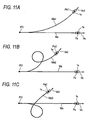
- a problem could be revealed in the related rotation angle calculating method, since the rotation angle is calculated by merely considering only predetermined measuring points in the initial shape and the final shape. This problem will now be explained with Figs. 11A to 11C and Fig. 12 .
- Fig. 11A to Fig. 11C are diagrams showing three typical patterns which may possibly occur when wire harnesses are deformed from initial shapes thereof to final shapes thereof.
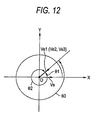
- Fig. 12 is a diagram showing measuring points in both the initial shapes and the final shapes by employing vectors shown in Figs. 11A to Fig. 11C . It should be noted that for the sake of simple explanations, although the initials shapes are assumed as linear shapes, these initial shapes are not limited to the linear shapes.
- the initial shapes Ws of the wire harnesses are commonly equal to each other, and directions of the connectors 1 s in the final shapes are equal to each other.
- the directions of the connectors 1 s in the initial shapes Ws are expressed by a vector Vs;
- the directions of the connectors 1 s in the finals shapes We1, We2, We3 are expressed by a vector Ve1, a vector Ve2, and a vector Ve3, respectively.
- these vectors may be represented as shown in Fig. 12 .
- the coupling points of the plural elements, the fixed point, and the measuring point are set as the node respectively;
- the tangent vector at the measuring point of the initial shape is set as a reference tangent vector;
- the tangent vectors at the respective nodes of the final shape are set as tangent vectors respectively.
- the angles which involve the rotation directions and are defined between the respective tangent vectors at the respective adjoining nodes are calculated as respective angles, and the respective angles are added to each other so as to calculate the rotation angle involving the rotation direction at the measuring point.
- the rotation angle may involve such rotation angles larger than, or equal to 360 degrees.
- the coupling points of the plural elements, the fixed point, and the measuring point are set as the node respectively;
- the tangent vector at the measuring point of the initial shape is set as a reference tangent vector;
- the tangent vector at the measuring point of the final shape as a final tangent vector;
- the respective sequence of points vectors which are obtained from the lines for connecting the respective adjoining nodes of the final shape are set as respective sequence of points vectors.
- the angle involving the rotation angle which is defined between the reference tangent vector and the sequence of points vector while the fixed point is defined as a starting point; the angle involving the rotation angle, which is defined between the respective sequence of points vectors where the respective adjoining nodes are defined as starting points; and the angle involving the rotation angle, which is defined between the sequence of points vector directed to the measuring point and the final tangent vector are calculated as respective angles.
- the respective angles are added to each other so as to calculate the rotation angle involving the rotation direction at the measuring point. It should also be understood that the rotation angle may involve such rotation angles larger than, or equal to 360 degrees.
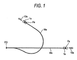
- Fig. 1 is a diagram showing both an initial shape and a final shape of a wire harness in order to explain both a first embodiment and a second embodiment of the present invention.
- Fig. 2 is block diagram showing hardware according to the present invention.
- Fig. 3 is a flow chart showing a process sequential operation of a computer according to the first embodiment of the present invention.
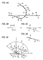
- Fig. 4A to Fig. 4E are diagrams for explaining a calculation method of a rotation angle according to the first embodiment of the present invention.
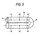
- Fig. 5 is a diagram for explaining a desirable node-to-node distance.
- an elongated hole type connector 1 s which is mounted on one end of a wire harness shown in "Ps" is rotated by an angle " ⁇ " to be displayed up to a position shown in "Pe", and thus, the wire harness is deformed from an initial shape "Ws” having a linear shape up to a final shape "We.”
- the other end of the wire harness is located at a fixed point "P0.”
- the elongated hole type connector 1s has a shape of a rectangular flat plane.
- the connector 1s has an elongated hole shaped mounting shaft portion which is inserted into an elongated hole pierced in a body of a vehicle.
- a longitudinal direction of the connector 1 s is directed to such a direction shown by "10s" in the initial shape Ws, and is directed to such a direction shown by "10e” in the final shape We.
- a rotation angle (alternatively, may becomes larger than, or equal 360 degrees) which is defined by the direction 10s of the connector 1 s in the initial shape Ws and the direction 10e of the connector 1 s in the final shape We is calculated, while a rotation direction is involved in the rotation angle.
- this hardware will now be explained with reference to Fig. 2 .
- a desk top type computer As indicated in Fig. 2 , as the hardware used to realize the present invention, for instance, either a well-known notebook type computer, a desk top type computer is employed.
- the computer includes a microcomputer 11, an input device 12, a display device 13, a printing device 14, a storage device 15, a communication interface 16 and a read/write device 17.
- the microcomputer 11 contains a CPU (central processing unit) 11 a, a ROM 11b, and a RAM 11c.
- the ROM 11b stores a boot program, and the like thereinto.
- the RAM 11c temporarily stores various sorts of processed results thereinto.
- the input device 12 corresponds to a keyboard, a mouse, and the like, which are used to input the various values.
- the display device 13 corresponds to an LCD, a CRT, and the like, which display a processed result.
- the printing device 14 corresponds to a printer for printing a processed result.
- the storage device 15 corresponds to, for instance, a hard disk drive which stores an installed rotation angle calculation program 19a, a processed result obtained by this rotation angle calculation program 19a, and the like thereinto.
- the communication interface 16 corresponds to a modem board, and the like, which performs a data communication operation with respect to another apparatus by employing, for example, a leased line, a LAN, the Internet, and so on.
- the read/write device 17 corresponds to such an apparatus which reads the rotation angle calculation program 19 which is stored in the recording medium 19 such as a CR-ROM and a DVD-ROM; which reads initial shape data and final shape data, which are stored in the storage medium 19; and which writes a calculated rotation angle into the recording medium 19.
- the rotation angle calculation program 19a any one of programs corresponding to the first embodiment through a fourth embodiment (will be explained later) may be employed.
- the microcomputer 11 installs the rotation angle calculations program 19a which is read by the read/write device 17 into the storage device 15. Also, after the power supply is turned ON, the microcomputer 11 is initiated in accordance with the boot program which is stored in the ROM 11 b, and boots the installed rotation angle calculation program 19a. Then, the microcomputer 11 may calculate a rotation angle of a wire harness, may output the calculated rotation angle to the display device 13 and/or the printing device 14, and may store this calculated result into the storage device 15 in accordance with the rotation angle calculation program 19a.
- the rotation angle calculation program 19a may also be installed into another personal computer, or the like, which contains the above-described basic construction. After this rotation angle calculation program 19a is installed in the personal computer, this personal computer may function as a rotation angle calculating apparatus.
- the rotation angle calculation program 19a may be provided from not only the recording medium 19, but also may be provided via a communication line such as the Internet and a LAN.
- both initial shape data and final shape data are acquired.
- Both the initial shape data and the final shape data may be previously stored in the storage medium 19, and both the initial shape data ant the final shape data are read by operating the read/write device 17.
- the initial shape data and the final shape data may be acquired via a LAN, the Internet, or the like.
- data which have been inputted through the input device 12 may be acquired.
- both the initial shape data and the final shape data are preferably displayed on the display device 13 in the form of such an image shown in Fig. 1 .
- a node setting operation is carried out.
- a portion of the wire harness between a fixed point "NO” (corresponding to fixed point "P0" of Fig. 1 ) of the final shape We and an arbitrary measuring point, for instance, a point "Ne” (corresponding to point "Pe” of Fig. 1 ) where the connector 1 s is mounted are segmented to a plurality of elements.
- the measuring point Ne is not limited to an end point of the wire harness.
- the measuring point may be an intermediate point of the wire harness.
- a center line of a wire harness having a predetermined width may be utilized.
- the step S103 corresponds to a node setting step and a node setting unit.
- a distance "R” between successive nodes i.e., n1-n2, ⁇ , n5-n6, ⁇ , smaller than, ⁇ d/2.
- a dot line indicates a center line of the wire harness W, and the center line is utilized to form both a model of the initial shape Ws and a shape of the final shape We in Fig. 4A .
- a vector setting operation is carried out.
- a tangent vector at the measuring point Ns of the initial shape Ws is set as a reference tangent vector "Vs.”
- tangent vectors at the respective nodes No, ⁇ , Ne of the final shape We are set as tangent vectors "V0", ⁇ , "Ve", respectively.
- Both the reference tangent vector Vs and the respective tangent vectors V0, ⁇ , Ve are set as unit vectors having specific directions.
- the step S104 corresponds to a reference tangent vector setting step, the tangent vector setting step, the reference tangent vector setting step, and the tangent vector setting unit.
- each of angles " ⁇ i" is calculated.
- Fig. 4B first of all, an angle “ ⁇ 0" defined between the reference tangent vector Vs and a first tangent vector V0 is calculated.
- Fig. 4C an angle “ ⁇ 1” defined between the first tangent vector V0 and a next tangent vector V1 is calculated.
- Fig. 4D an angle “ ⁇ 2" defined between the tangent vector V1 and next tangent vector V2 is calculated. That is, as shown in Fig. 4E , the respective angles ⁇ 0, ⁇ , ⁇ 6 are sequentially calculated.
- the step S105 corresponds to an angle calculating step and an angle calculating unit.
- rotation directions of the respective angles " ⁇ i" may be expressed.
- directions may be expressed in such a manner that an angle change from the vector V0 to the vector V1 is expressed as plus (+), whereas an angle change from the vector V1 to the vector V2 is expressed as minus (-).
- a calculating operation as to a final rotation angle " ⁇ " is carried out in a step S106 of Fig. 3 .
- This rotation angle " ⁇ ” corresponds to such an angle which is defined by both the above-described reference tangent vector Vs and the final tangent vector Ve, and which involves a rotation direction.
- the step S106 corresponds to a rotation angle calculating step and a rotation angle calculating unit.
- This rotation angle ⁇ which has been calculated is outputted.
- This rotation angle ⁇ may be alternatively displayed on the display device 13, or may be alternatively printed out by the printing device 14. Further, this rotation angle ⁇ may be alternatively stored in the storage device 15, may be alternatively recorded via the read/write device 17 onto the recording medium 19, or may be alternatively outputted through both the communication I/F 16 and the Internet, a LAN, etc. to other apparatus. Also, as a display image displayed on the display device 13, a figure, a character, a numeral, or a combination of these elements may be alternatively displayed on the display device 13, or the like.
- the rotation angles involving the rotation directions can be calculated at the arbitrary measuring points on the wire harness.
- the respective adjoining nodes are set with respect to the final shape.
- the wire harness is deformed from the initial shape having the linear shape.
- Fig. 6 is a flow chart for describing a process operation of the computer, according to a second embodiment of the present invention.
- Figs. 7A to 7E are explanatory diagrams for explaining a calculation method of a rotation angle according to the second embodiment of the present invention.
- a description is made by supposing both the initial shape and the final shape of such a wire harness shown in Fig. 1 .
- the hardware exemplified in Fig. 2 is similarly utilized.
- both initial shape data and final shape data are acquired.
- a step S203 a node setting operation is carried out. Since these data acquiring/node setting process operations are equivalent to those defined in the step S101, the step S102, and the step S103 of the first embodiments, duplicated explanations thereof are omitted. Similar to the first embodiment, a distance "R" between the respective adjoining nodes may be preferably made shorter than ⁇ d/2 in Fig. 5 .
- the step S203 corresponds to a node setting step.
- a vector setting operation is carried out.
- a tangent vector at the measuring point Ns of the initial shape Ws is set as a reference tangent vector "Vs.”
- a tangent vector at the measuring point Ne (see Fig. 1 ) of the final shape We is set as a final tangent vector "Ve.”
- respective sequence of points vectors which are obtained from lines connecting the respective adjoining nodes N0, ⁇ , Ne of the final shape We are set as sequence of points vectors W0, ⁇ , W5, respectively.
- the reference tangent vector Vs, the final tangent vector Ve, and the respective sequence of points vectors W0, ⁇ , W5 are also set as unit vectors having specific directions, respectively. As to directions of the reference tangent vector Vs, the final tangent vector Ve, and the respective sequence of points vectors W0, ⁇ , W5, such tangent vectors which are largely directed to measuring points are set.
- the step S204 corresponds to a reference tangent vector setting step, a final tangent vector setting step, and a sequence of points vector setting step.
- each angle " ⁇ i" is calculated.
- Fig. 7B first of all, an angle “ ⁇ 0" defined between the reference tangent vector Vs and a first sequence of points vector W0 is calculated.
- Fig. 7C an angle “ ⁇ 1” defined between the first sequence of points vector W0 and a next sequence of points vector W1 is calculated.
- Fig. 7D an angle “ ⁇ 2" defined between the sequence of points vector W1 and a next sequence of points vector W2 is calculated. That is, as shown in Fig. 7E , the respective angles ⁇ 0, ⁇ , ⁇ 6 are sequentially calculated.
- the final angle " ⁇ 6" corresponds to such an angle defined between the sequence of points vector W5 and the final tangent vector Ve. Similar to the first embodiment, the definitions as to the vector inner product and the vector outer product are utilized so as to calculate the respective angles " ⁇ i.”
- the step S205 corresponds to an angle calculating step.
- a calculating operation as to a final rotation angle " ⁇ " is carried out in a step S206.
- This rotation angle " ⁇ ” corresponds to such an angle which is defined by both the above-described reference tangent vector Vs and the final tangent vector Ve, and which involves a rotation direction. As apparent from the foregoing description, there are some possibilities that the rotation angle " ⁇ " may become larger than, or equal to 360 degrees.
- the step S206 corresponds to a rotation angle calculating step.
- a step S207 the rotation angle ⁇ which has been calculated in the above-explained manner is outputted.
- This rotation angle ⁇ may be alternatively displayed on the display device 13, or may be alternatively printed out by the printing device 14. Further, this rotation angle ⁇ may be alternatively outputted to the storage device 15, may be alternatively outputted via the read/write device 17 onto the recording medium 19, or may be alternatively outputted through both the communication I/F 16 and the Internet, a LAN, etc. to other apparatus. Also, as a display image displayed on the display device 13, a figure, a character, a numeral, or a combination of these elements may be alternatively displayed on the display device 13, or the like.
- the respective angles are calculated by utilizing the sequence of points vectors which are obtained from the line connecting the respective nodes in the final shape, and then, these calculated angles are added to each other.
- the rotation angles involving the rotation directions can be calculated at the arbitrary measuring points on the wire harness which has been deformed from the initial shape having the linear shape. More specifically, since the sequence of points vectors are obtained from the lines which connect the respective nodes to each other, the vector setting operation required in the angle calculation can be readily carried out.
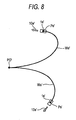
- Fig. 8 is a diagram showing both an initial shape and a final shape of a wire harness according the third embodiment of the present invention.
- Fig. 9 is a flow chart for describing a process operation of the computer according to the third embodiment.
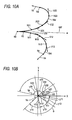
- Fig. 10A and Fig. 10B are explanatory diagrams for explaining a calculating method of a rotation angle according to the third embodiment. In this third embodiment, the hardware shown in Fig. 2 is similarly utilized.
- an initial shape "Ws"' of a wire harness having a non-linear shape is deformed as a final shape "We"' having a non-linear shape. Since an elongated hole type connector "1s"' which is mounted on one edge of such a wire harness shown in "Ps"' is rotated by an angle of " ⁇ " and then is displaced up to such a position shown in "Pe”', the wire harness is deformed from the initial shape Ws' to the final shape We'. In this case, the other edge of the wire harness is assumed as a fixed point "P0'.” The connector 1s' completely restricts a fixing portion of this connector 1s'.
- a longitudinal direction of the connector 1 s' is directed to such a direction indicated by symbol “10s'” in the initial shape Ws', and then, the longitudinal direction thereof is directed to such a direction indicated by symbol “10e”” in the final shape We'.
- such a rotation angle (alternatively, may becomes larger than, or equal 360 degrees) which is defined by the direction 10s' of the connector 1 s' in the initial shape Ws' and the direction 10e' of the connector 1 s' in the final shape We' is calculated, while a rotation direction is contained.
- both initial shape data and final shape data are acquired.
- Both the initial shape data and the final shape data may be alternatively acquired in such a manner that such shape data which have been previously stored in the above-explained storage medium 19 are read by operating the read/write device 17.
- the initial shape data and the final shape data may be acquired via a LAN, the Internet, or the like.
- data which have been inputted by employing the input device 12 may be acquired.
- Both the initial shape data and the final shape data, which have been acquired, are preferably displayed on the display device 13 in the form of such an image shown in Fig. 8 .
- a node setting operation is carried out.
- a portion of the wire harness between a fixed point "N0" (corresponding to fixed point P0' of Fig. 8 ) of the initial shape Ws', and an arbitrary measuring point, for instance, a point "Ns" (corresponding to point Ps' of Fig. 8 ) where the connector 1s' is mounted are segmented to a plurality of elements. Under this condition, coupling points of these elements, the fixed point "N0", and the measuring point "Ns" are set as nodes "N0", N11, ⁇ , N13, and Ns.
- the measuring point Ne is not limited to an end point of the wire harness, but the measuring point Ne may be an intermediate point of the wire harness.
- a portion of the wire harness between a fixed point "N0" (apparently, coincident with fixed point N0 of initial shape Ws') of the final shape We', and a point "Ne" (corresponding to Pe' of Fig. 8 ) where the connector 1s' is mounted are segmented to a plurality of elements. Then, coupling points of these elements, the fixed point N0, and the measuring point Ne are set as nodes N0, N21, ⁇ , N23, and Ne.
- a virtual initial shape "W0"' having a linear shape is set which corresponds to the tangent vector V0 at the fixed point N0.
- a final rotation angle is calculated.
- a distance "R" between the respective nodes is preferably smaller than ⁇ d/2 in Fig. 5 similar to the first embodiment.
- a vector setting operation is carried out.
- This vector setting operation is performed in a similar manner to that of the step S104 of the first embodiment.
- respective tangent vectors at respective nodes N0, N11, ⁇ , N13, and Ns of the initial shape Ws' are set as respective tangent vectors V0, V11, ⁇ , V13, and V2
- respective tangent vectors at respective nodes N21, ⁇ , N23, and Ne of the final shape We' are set as respective tangent vectors V21, ⁇ , V23, and Ve.
- the reference tangent vector Vs, and the respective tangent vectors V0, V11, ⁇ , V13, and Vs, V21, ⁇ , V23, and Ve are set as unit vectors having specific directions, respectively. As to directions of these vectors, tangent vectors which are further directed to the measuring points are set.
- a calculation of respective angles " ⁇ 2j" is carried out in such an assumption case that the virtual initial shape W0' is deformed to the final shape We'.
- the definitions as to the vector inner product and the vector outer product which are well known in this field, are also utilized to the calculations of the respective angles ⁇ 2j.
- a final rotation angle " ⁇ " is calculated in a step S307.
- an angle of "- ⁇ 1i” is added to a second rotation angle “ ⁇ 2j” so as to calculate the final rotation angle ⁇ .
- the final rotation angle " ⁇ " corresponds to such an angle which involves rotation direction and which is defined between the reference tangent vector Vs and the final respective tangent vectors Ve, and there are some possibilities that this final rotation angle " ⁇ " may become larger than, or equal to 360 degrees.
- a step S308 the rotation angle ⁇ which has been calculated in the above-explained manner is outputted.
- This rotation angle ⁇ may be alternatively displayed on the display device 13, or may be alternatively printed out by the printing device 14. Further, this rotation angle ⁇ may be alternatively stored in the storage device 15, may be alternatively recorded via the read/write device 17 onto the recording medium 19, or may be alternatively outputted through both the communication I/F 16 and the Internet, a LAN, etc. to other apparatus. Also, as a display image displayed on the display device 13, a figure, a character, a numeral, or a combination of these elements may be alternatively displayed on the display device 13, or the like.
- both the rotation angle in the case that the virtual initial shape is deformed into the initial shape, and also, the rotation angle in such a case that the virtual initial shape is deformed into the final shape are calculated by utilizing the tangent vectors as explained above, respectively.
- a rotation angle involving a rotation direction may also be calculated at an arbitrary measuring point on a wire harness whose shape has been deformed from an initial shape having a non-linear shape.
- a rotation angle in the case that both an initial shape and a final shape are commonly equal to non-linear shapes may be furthermore calculated as a fourth embodiment.
- this fourth embodiment while a virtual initial shape having a linear shape is supposed, this virtual initial shape is deformed into both an initial shape and a final shape, which own non-linear shapes, and then, a final rotation angle is calculated.
- the final rotation angle is calculated by utilizing such sequence of points vectors shown in the second embodiment instead of the respective tangent vectors of the third embodiments.
- both the rotation angle calculating method of the wire harness, the rotation angle calculating apparatus, and the recording medium storing rotation angle calculating program can be provided by which the rotation angles including the rotation directions can be correctly calculated, although the related technique could not correctly calculate the rotation angles involving the rotation directions.
- rotation angles in a three-dimensional space may be similarly calculated.
- the present invention may cover the rotation angle calculating operation in the three-dimensional space.
- a measuring point used to calculate a rotation angle is not limited only to an edge point of a wire harness, but may be alternatively set to an intermediate point of the wire harness. Further, a plurality of measuring points may be alternatively employed.
- the present invention may cover such a modification example which has been modified within a range which is not deviated from the technical scope of the present invention as claimed.
- the rotation angle involving the rotation direction at the arbitrary measuring point on the wire harness deformed from the linear shape can be calculated.
- the respective angles are calculated, and then, the calculated angles are added to each other.
- the rotation angle involving the rotation direction at the arbitrary measuring point on the wire harness deformed from the linear shape can be calculated.
- the vector setting operations required for calculating the angles can also be easily carried out.
- the rotation angle in the case that the virtual initial shape is deformed to the initial shape and the rotation angle in the case that the virtual initial shape is deformed to the final shape are calculated respectively by utilizing the tangent vectors, as explained above.
- a rotation angle can also be calculated which involve a rotation direction and which is located at an arbitrary measuring point on a wire harness which has been deformed from an initial shape equal to a non-linear shape.
- the rotation angle in the case that the virtual initial shape is deformed to the initial shape and the rotation angle in the case that the virtual initial shape is deformed to the final shape are calculated respectively by utilizing the sequence of points vectors, as explained above.
- a rotation angle can also be calculated which involve a rotation direction and which is located at an arbitrary measuring point on a wire harness which has been deformed from an initial shape equal to a non-linear shape.
- the sequence of points vectors are obtained from the lines for connecting the respective nodes, the vector setting operations required for calculating the angles can also be easily carried out.
Landscapes
- Engineering & Computer Science (AREA)
- Theoretical Computer Science (AREA)
- Physics & Mathematics (AREA)
- General Engineering & Computer Science (AREA)
- Evolutionary Computation (AREA)
- Geometry (AREA)
- Computer Hardware Design (AREA)
- General Physics & Mathematics (AREA)
- Mechanical Engineering (AREA)
- Image Analysis (AREA)
- Length Measuring Devices With Unspecified Measuring Means (AREA)
- Image Processing (AREA)
- Details Of Indoor Wiring (AREA)
- Installation Of Indoor Wiring (AREA)
Claims (9)
- Drehwinkelberechnungsverfahren für einen Kabelbaum, wobei der Drehwinkel des Kabelbaums an einem beliebigen Messpunkt (Ne) des Kabelbaums berechnet wird, wenn der Kabelbaum von einer ersten Form (Ws) zu einer zweiten Form (We) verformt wird, während ein fixer Punkt (N0) des Kabelbaums fixiert ist, wobei das Drehwinkelberechnungsverfahren die folgenden Schritte umfasst:Setzen einer Vielzahl von Zwischenpunkten (N1, N2, N3, N4, N5) zwischen dem fixierten Punkt (N0) und dem Messpunkt (Ne) des Kabelbaums in der zweiten Form (We), wobei der fixe Punkt (N0), der Messpunkt (Ne) und die Zwischenpunkte (N1, N2, N3, N4, N5) jeweils als Knoten gesetzt werden,Setzen eines Tangentenvektors an dem Messpunkt (Ns := Ne) des Kabelbaums in der ersten Form (Ws) als einen Bezugs-Tangentenvektor (Vs),Setzen von Vektoren an den Knoten (N0, N1, N2, N3, N4, N5, Ne) des Kabelbaums in der zweiten Form (We) jeweils als Knotenvektoren (V0, V1, V2, V3, V4, V5, Ve),Berechnen eines Winkels (α0), der zwischen dem Bezugs-Tangentenvektor (Vs) und dem ersten Knotenvektor (V0; W0) definiert ist, an dem fixen Punkt (N0) als Startpunkt,Berechnen von Winkeln (αi), die jeweils eine Drehrichtung aufweisen, wobei jeder der Winkel (αi) zwischen den Knotenvektoren (V0, V1, V2, V3, V4, V5, Ve) an den benachbarten Knoten definiert ist, undAddieren der Winkel (α0, αi) miteinander, um einen Drehwinkel (Θ) mit einer Drehrichtung an dem Messpunkt (Ne) zu berechnen.
- Drehwinkelberechnungsverfahren nach Anspruch 1, wobei die Vektoren (V0, V1, V2, V3, V4, V5, Ve) an den Knoten (N0, N1, N2, N3, N4, N5, Ne) des Kabelbaums in der zweiten Form Tangentenvektoren sind.
- Drehwinkelberechnungsverfahren nach Anspruch 1, das weiterhin die folgenden Schritte umfasst:Setzen eines Tangentenvektors an dem Messpunkt (Ne) des Kabelbaums in der zweiten Form (We) als einen endgültigen Tangentenvektor (Ve),wobei die Vektoren an den Zwischenpunkten (N1, N2, N3, N4, N5) der Knoten des Kabelbaums in der zweiten Form (We) eine Folge von Punktvektoren sind, die jeweils aus Linien (W0, W1, W2, W3, W4, W5) erhalten werden, die die entsprechenden benachbarten Knoten des Kabelbaums in der zweiten Form (We) verbinden, undwobei in dem Winkelberechnungsschritt ein Winkel, der zwischen dem Bezugs-Tangentenvektor (Vs) und der ersten Folge von Punktvektoren an dem fixen Punkt (P0) als ein Startpunkt definiert ist, ein Winkel mit einem Drehwinkel, der zwischen den entsprechenden Folgen von Punktvektoren an den entsprechenden benachbarten Zwischenpunkten der Knoten als Starpunkte definiert ist, und ein Winkel mit einem Drehwinkel, der zwischen der zu dem Messpunkt gerichteten Folge von Punktvektoren und dem endgültigen Tangentenvektor definiert ist, berechnet werden.
- Drehwinkelberechnungsverfahren nach Anspruch 2, das weiterhin die folgenden Schritte umfasst:Setzen einer virtuellen Form mit einer linearen Form, die sich in einer Richtung eines Tangentenvektors an dem fixen Punkt erstreckt, wenn die erste Form (Ws) und die zweite Form (We) des Kabelbaums beide nicht-lineare Formen sind,Berechnen eines ersten Drehwinkels (γ1i) an dem Messpunkt, wenn der Kabelbaum von der virtuellen Form zu der ersten Form (Ws) verformt wird, während der fixe Punkt des Kabelbaums fixiert ist, durch das Durchführen des Knotensetzschritts, des Vektorsetzschritts,des Winkelberechnungsschritts und des Winkeladditionsschritts,Berechnen eines zweiten Drehwinkels (γ2i) an dem Messpunkt, wenn der Kabelbaum von der virtuellen Form zu der zweiten Form (We) verformt wird, während der fixe Punkt des Kabelbaums fixiert ist, durch das Durchführen des Knotensetzschritts, des Vektorsetzschritts, des Winkelberechnungsschritts und des Winkeladditionsschritts, undBerechnen eines Drehwinkels mit einer Drehrichtung an dem Messpunkt, wenn der Kabelbaum von der ersten Form (Ws) zu der zweiten Form (We) verformt wird, basierend auf den ersten und zweiten Drehwinkeln.
- Drehwinkelberechnungsverfahren nach Anspruch 3, das weiterhin umfasst:Setzen einer virtuellen Form mit einer linearen Form, die sich in einer Richtung eines Tangentenvektors erstreckt, an dem fixen Punkt, wenn die erste Form (Ws) und die zweite Form (We) des Kabelbaums nicht-lineare Formen sind,Berechnen eines ersten Drehwinkels (γ1i) an dem Messpunkt, wenn der Kabelbaum von der virtuellen Form zu der ersten Form (Ws) verformt wird, während der fixe Punkt des Kabelbaums fixiert ist, durch das Durchführen des Knotensetzschritts, des Vektorsetzschritts, des Bezugs-Tangentenvektorsetzschritts, des Endgültiger-Tangentenvektorsetzschritts, des Winkelberechnungsschritts und des Winkeladditionsschritts,Berechnen eines zweiten Drehwinkels (γ2i) an dem Messpunkt, wenn der Kabelbaum von der virtuellen Form zu der zweiten Form (We) verformt wird, während der fixe Punkt des Kabelbaums fixiert ist, durch das Durchführen des Knotensetzschritts, des Vektorsetzschritts, des Bezugs-Tangentenvektorsetzschritts, des Endgültiger-Tangentenvektorsetzschritts, des Winkelberechnungsschritts und des Winkeladditionsschritts, undBerechnen eines Drehwinkels mit einer Drehrichtung an dem Messpunkt, wenn der Kabelbaum von der ersten Form (Ws) zu der zweiten Form (We) verformt wird, basierend auf den ersten und zweiten Drehwinkeln.
- Drehwinkelberechnungsverfahren nach Anspruch 1, wobei die Vielzahl von Knoten auf einer Mittenlinie des Kabelbaums gesetzt wird.
- Drehwinkelberechnungsverfahren nach Anspruch 1, wobei die Distanz zwischen den benachbarten Knoten gemäß der folgenden Formel gesetzt wird, dass die Distanz R kleiner als π.d/2 ist, wobei "d" der Durchmesser des Kabelbaums ist.
- Computerlesbares Aufzeichnungsmedium, das einen Computer veranlasst, das Drehwinkelberechnungsverfahren nach einem der Ansprüche 1 bis 7 auszuführen.
- Drehwinkelberechnungsvorrichtung zum Berechnen eines Drehwinkels eines Kabelbaums an einem beliebigen Messpunkt (Ne) des Kabelbaums, wenn der Kabelbaum von einer ersten Form (Ws) zu einer zweiten Form (We) verformt wird, während ein fixer Punkt (N0) des Kabelbaums fixiert ist, wobei die Drehwinkelberechnungsvorrichtung umfasst:eine Knotensetzeinheit, die eine Vielzahl von Zwischenpunkten (N1, N2, N3, N4, N5) zwischen dem fixen Punkt (N0) und dem Messpunkt (Ne) des Kabelbaums in der zweiten Form (We) setzt, wobei der fixe Punkt (N0), der Messpunkt (Ne) und die Zwischenpunkte (N1, N2, N3, N4, N5) jeweils als Knoten gesetzt werden,eine Bezugs-Tangentenvektor (Vs)-Setzeinheit, die einen Tangentenvektor (Vs) an dem Messpunkt (Ns := Ne) des Kabelbaums in der ersten Form (Ws) als einen Bezugs-Tangentenvektor (Vs) setzt,eine Knotenvektor-Setzeinheit, die Vektortangenten zu dem Kabelbaum an den Knoten (N0, N1, N2, N3, N4, N5, Ne) des Kabelbaums in der zweiten Form (We) jeweils als Knotenvektoren (V0, V1, V2, V3, V4, V5, Ve) setzt,eine Startpunktwinkel-Berechnungseinheit, die einen Winkel (α0), der zwischen dem Bezugs-Tangentenvektor (Vs) und dem ersten Knotenvektor (V0; W0) definiert ist, an dem fixen Punkt (N0) als Startpunkt berechnet,eine Winkelberechnungseinheit, die Winkel (αi), die jeweils eine Drehrichtung aufweisen, berechnet, wobei jeder der Winkel (αi) zwischen den Knotenvektoren (V0, V1, V2, V3, V4, V5, Ve) an den benachbarten Knoten definiert ist, undeine Winkeladditionseinheit, die die Winkel (α0, αi) miteinander addiert, um einen Drehwinkel (Θ) mit einer Drehrichtung an dem Messpunkt (Ne) zu berechnen.
Applications Claiming Priority (2)
| Application Number | Priority Date | Filing Date | Title |
|---|---|---|---|
| JP2003204374A JP4383114B2 (ja) | 2003-07-31 | 2003-07-31 | ワイヤーハーネスの回転角度計算方法、その装置及びそのプログラム |
| PCT/JP2004/011107 WO2005012830A2 (en) | 2003-07-31 | 2004-07-28 | Rotation angle calculating method of wire harness, rotation angle calcurating appratus, and computer-readable recording medium |
Publications (2)
| Publication Number | Publication Date |
|---|---|
| EP1649239A2 EP1649239A2 (de) | 2006-04-26 |
| EP1649239B1 true EP1649239B1 (de) | 2014-04-09 |
Family
ID=34113644
Family Applications (1)
| Application Number | Title | Priority Date | Filing Date |
|---|---|---|---|
| EP04771160.1A Expired - Lifetime EP1649239B1 (de) | 2003-07-31 | 2004-07-28 | Drehwinkel-berechnungsverfahren eines kabelbaums, drehwinkel-berechnungsvorrichtung und computerlesbares aufzeichnungsmedium |
Country Status (6)
| Country | Link |
|---|---|
| US (1) | US7395179B2 (de) |
| EP (1) | EP1649239B1 (de) |
| JP (1) | JP4383114B2 (de) |
| KR (1) | KR100752441B1 (de) |
| CN (1) | CN101124106B (de) |
| WO (1) | WO2005012830A2 (de) |
Families Citing this family (9)
| Publication number | Priority date | Publication date | Assignee | Title |
|---|---|---|---|---|
| JP4804501B2 (ja) * | 2008-04-16 | 2011-11-02 | 関東自動車工業株式会社 | ワイヤハーネスの配索形状表示装置 |
| CN102096307A (zh) * | 2009-12-14 | 2011-06-15 | 鸿富锦精密工业(深圳)有限公司 | 测试相机镜头偏转角度的方法和装置 |
| FR2974268B1 (fr) * | 2011-04-13 | 2013-05-31 | Dassault Aviat | Procede de determination du positionnement angulaire d'un composant monte sur un cheminement filiforme, methode d'assemblage et systeme associes |
| JP5166579B2 (ja) * | 2011-08-04 | 2013-03-21 | ファナック株式会社 | 線条体の振る舞いをシミュレートするロボットシミュレーション装置 |
| JP5882661B2 (ja) * | 2011-10-13 | 2016-03-09 | キヤノン株式会社 | 3次元コンピュータ設計支援プログラム、コンピュータ読取可能な記録媒体、3次元コンピュータ設計支援システム及び3次元コンピュータ設計支援方法 |
| CN102629292B (zh) * | 2012-03-26 | 2014-04-09 | 河北省送变电公司 | 连接管钢梁不同平面间的斜角钢制弯计算方法 |
| JP5927270B2 (ja) * | 2014-11-06 | 2016-06-01 | ファナック株式会社 | ロボットシミュレーション装置 |
| US10635777B2 (en) * | 2016-02-16 | 2020-04-28 | Bayerische Motoren Werke Aktiengesellschaft | Method for generating and using a two-dimensional drawing having three-dimensional orientation information |
| JP7570966B2 (ja) * | 2021-04-15 | 2024-10-22 | 株式会社神戸製鋼所 | 多関節ロボットの線状部材形状シミュレータ、該方法および該プログラム |
Family Cites Families (10)
| Publication number | Priority date | Publication date | Assignee | Title |
|---|---|---|---|---|
| JPH0736193B2 (ja) * | 1989-09-21 | 1995-04-19 | 日産自動車株式会社 | 線状物体のレイアウト解析cadシステム |
| US5506950A (en) * | 1992-12-18 | 1996-04-09 | Computervision Corporation | Method and apparatus for producing a three dimensional representation of a wire harness into a two dimensional presentation |
| JP2993341B2 (ja) * | 1993-12-24 | 1999-12-20 | 日産自動車株式会社 | 線条材のシミュレーション方法 |
| JP2001250438A (ja) * | 2000-03-02 | 2001-09-14 | Mazda Motor Corp | 線条材の配線設計支援装置及び配線設計方法及びコンピュータ読み取り可能な記憶媒体 |
| EP1236989B1 (de) * | 2001-03-02 | 2012-09-19 | Sumitomo Wiring Systems, Ltd. | Verfahren und Programm zur Konstruktion eines Kabelbaums und Verfahren zum Schätzen seiner Biegungsdauer |
| EP1267285A3 (de) * | 2001-06-13 | 2003-02-12 | Sumitomo Wiring Systems, Ltd. | Verfahren, Computerprogramm und System zum Entwurf einer Kabelbaum-Montagetabelle |
| JP3692971B2 (ja) * | 2001-06-13 | 2005-09-07 | 住友電装株式会社 | 3次元仮想組立システム |
| JP2003022721A (ja) * | 2001-07-09 | 2003-01-24 | Sumitomo Wiring Syst Ltd | ワイヤーハーネス設計支援方法及びプログラム |
| US20030030206A1 (en) * | 2001-07-23 | 2003-02-13 | Yazaki Corporation | Wire harness arranging-purpose wire holding member and wire harness arranging-method |
| US7444269B2 (en) * | 2001-09-29 | 2008-10-28 | The Boeing Company | Constraint-based method of designing a route for a transport element |
-
2003
- 2003-07-31 JP JP2003204374A patent/JP4383114B2/ja not_active Expired - Fee Related
-
2004
- 2004-07-28 KR KR1020067002096A patent/KR100752441B1/ko not_active Expired - Fee Related
- 2004-07-28 EP EP04771160.1A patent/EP1649239B1/de not_active Expired - Lifetime
- 2004-07-28 US US10/566,571 patent/US7395179B2/en not_active Expired - Fee Related
- 2004-07-28 CN CN2004800216585A patent/CN101124106B/zh not_active Expired - Lifetime
- 2004-07-28 WO PCT/JP2004/011107 patent/WO2005012830A2/en not_active Ceased
Also Published As
| Publication number | Publication date |
|---|---|
| WO2005012830A2 (en) | 2005-02-10 |
| JP4383114B2 (ja) | 2009-12-16 |
| US7395179B2 (en) | 2008-07-01 |
| JP2005050602A (ja) | 2005-02-24 |
| EP1649239A2 (de) | 2006-04-26 |
| WO2005012830A3 (en) | 2007-10-11 |
| CN101124106B (zh) | 2011-03-30 |
| KR20060040728A (ko) | 2006-05-10 |
| KR100752441B1 (ko) | 2007-08-27 |
| US20060241896A1 (en) | 2006-10-26 |
| CN101124106A (zh) | 2008-02-13 |
Similar Documents
| Publication | Publication Date | Title |
|---|---|---|
| EP1649239B1 (de) | Drehwinkel-berechnungsverfahren eines kabelbaums, drehwinkel-berechnungsvorrichtung und computerlesbares aufzeichnungsmedium | |
| EP1236989B1 (de) | Verfahren und Programm zur Konstruktion eines Kabelbaums und Verfahren zum Schätzen seiner Biegungsdauer | |
| EP1275565B1 (de) | Methode und Programm zum Kabelbaumentwurf | |
| EP1418513A2 (de) | CAD Vorrichtung, Verfahren, Programm und Speichermedium zum Entwurf eines Leitungsführung | |
| JP3726737B2 (ja) | ワイヤーハーネス設計システム | |
| US6968289B1 (en) | Method of predicting displacement range of wire harness, predicting device and predicting program | |
| JP5605540B2 (ja) | ワイヤハーネス導通検査方法およびワイヤハーネス導通検査プログラム | |
| EP2116976A2 (de) | Systeme und Verfahren mit Oberflächenanpassung | |
| US20090222121A1 (en) | Enhanced flattening for cable and wiring harnesses in computer-aided design drawings | |
| US7826989B2 (en) | Computer-readable medium storing electromagnetic field analysis program, and method of causing computer to perform electromagnetic field analysis | |
| EP1624396A1 (de) | Verfahren zur Berechnung der Gestalt einer Verdrahtung, Rechner und rechnerlesbares Aufzeichnungsmedium | |
| US20100070243A1 (en) | Wire Harness Unfolding | |
| US7337096B2 (en) | Calculation method for packing a plurality of wires and calculation apparatus using the same | |
| US11237931B2 (en) | Method and device for testing a technical system | |
| CN118484360A (zh) | 基于北斗系统的桥梁打桩机监控方法及其系统 | |
| US11592360B2 (en) | Method and device for testing a technical system | |
| JP2004119134A (ja) | ワイヤーハーネスの2次元展開方法及びその装置 | |
| Wakamatsu et al. | Fishbone Model for Belt Object Deformation. | |
| Koznov | Round-trip engineering of reactive systems | |
| EP3667546A1 (de) | Zeichnungszeugungsverfahren, kabelbaumherstellungsverfahren und zeichnungserzeugungsvorrichtung | |
| CN101630341B (zh) | 用于建立网格网络和估计围绕车身表面的空气流动的方法和系统 | |
| JP6981314B2 (ja) | 情報処理装置、シミュレーションプログラム及びシミュレーション方法 | |
| US7559013B2 (en) | Error detecting device, error detection method and control system | |
| van Holland et al. | Extracting grip areas from feature information | |
| JP5173942B2 (ja) | 保護継電装置 |
Legal Events
| Date | Code | Title | Description |
|---|---|---|---|
| PUAI | Public reference made under article 153(3) epc to a published international application that has entered the european phase |
Free format text: ORIGINAL CODE: 0009012 |
|
| 17P | Request for examination filed |
Effective date: 20060117 |
|
| AK | Designated contracting states |
Kind code of ref document: A2 Designated state(s): AT BE BG CH CY CZ DE DK EE ES FI FR GB GR HU IE IT LI LU MC NL PL PT RO SE SI SK TR |
|
| AX | Request for extension of the european patent |
Extension state: AL HR LT LV MK |
|
| DAX | Request for extension of the european patent (deleted) | ||
| RBV | Designated contracting states (corrected) |
Designated state(s): DE FR GB IT |
|
| PUAK | Availability of information related to the publication of the international search report |
Free format text: ORIGINAL CODE: 0009015 |
|
| 17Q | First examination report despatched |
Effective date: 20110523 |
|
| REG | Reference to a national code |
Ref country code: DE Ref legal event code: R079 Ref document number: 602004044795 Country of ref document: DE Free format text: PREVIOUS MAIN CLASS: G01B0007000000 Ipc: B60R0016020000 |
|
| GRAP | Despatch of communication of intention to grant a patent |
Free format text: ORIGINAL CODE: EPIDOSNIGR1 |
|
| RIC1 | Information provided on ipc code assigned before grant |
Ipc: G06F 17/50 20060101ALI20131011BHEP Ipc: B60R 16/02 20060101AFI20131011BHEP |
|
| INTG | Intention to grant announced |
Effective date: 20131104 |
|
| RIN1 | Information on inventor provided before grant (corrected) |
Inventor name: SAWAI, MASAYOSHI C/O YAZAKI PARTS CO. LTD. |
|
| GRAS | Grant fee paid |
Free format text: ORIGINAL CODE: EPIDOSNIGR3 |
|
| GRAA | (expected) grant |
Free format text: ORIGINAL CODE: 0009210 |
|
| AK | Designated contracting states |
Kind code of ref document: B1 Designated state(s): DE FR GB IT |
|
| REG | Reference to a national code |
Ref country code: GB Ref legal event code: FG4D |
|
| REG | Reference to a national code |
Ref country code: DE Ref legal event code: R096 Ref document number: 602004044795 Country of ref document: DE Effective date: 20140522 |
|
| REG | Reference to a national code |
Ref country code: DE Ref legal event code: R097 Ref document number: 602004044795 Country of ref document: DE |
|
| PLBE | No opposition filed within time limit |
Free format text: ORIGINAL CODE: 0009261 |
|
| STAA | Information on the status of an ep patent application or granted ep patent |
Free format text: STATUS: NO OPPOSITION FILED WITHIN TIME LIMIT |
|
| 26N | No opposition filed |
Effective date: 20150112 |
|
| GBPC | Gb: european patent ceased through non-payment of renewal fee |
Effective date: 20140728 |
|
| PG25 | Lapsed in a contracting state [announced via postgrant information from national office to epo] |
Ref country code: IT Free format text: LAPSE BECAUSE OF FAILURE TO SUBMIT A TRANSLATION OF THE DESCRIPTION OR TO PAY THE FEE WITHIN THE PRESCRIBED TIME-LIMIT Effective date: 20140409 |
|
| REG | Reference to a national code |
Ref country code: DE Ref legal event code: R097 Ref document number: 602004044795 Country of ref document: DE Effective date: 20150112 |
|
| PG25 | Lapsed in a contracting state [announced via postgrant information from national office to epo] |
Ref country code: GB Free format text: LAPSE BECAUSE OF NON-PAYMENT OF DUE FEES Effective date: 20140728 |
|
| REG | Reference to a national code |
Ref country code: FR Ref legal event code: PLFP Year of fee payment: 13 |
|
| REG | Reference to a national code |
Ref country code: FR Ref legal event code: PLFP Year of fee payment: 14 |
|
| REG | Reference to a national code |
Ref country code: FR Ref legal event code: PLFP Year of fee payment: 15 |
|
| PGFP | Annual fee paid to national office [announced via postgrant information from national office to epo] |
Ref country code: FR Payment date: 20230620 Year of fee payment: 20 |
|
| PGFP | Annual fee paid to national office [announced via postgrant information from national office to epo] |
Ref country code: DE Payment date: 20230531 Year of fee payment: 20 |
|
| REG | Reference to a national code |
Ref country code: DE Ref legal event code: R071 Ref document number: 602004044795 Country of ref document: DE |