EP1648686B1 - Procede et appareil pour frittage selectif d'un materiau particulaire - Google Patents
Procede et appareil pour frittage selectif d'un materiau particulaire Download PDFInfo
- Publication number
- EP1648686B1 EP1648686B1 EP04743477A EP04743477A EP1648686B1 EP 1648686 B1 EP1648686 B1 EP 1648686B1 EP 04743477 A EP04743477 A EP 04743477A EP 04743477 A EP04743477 A EP 04743477A EP 1648686 B1 EP1648686 B1 EP 1648686B1
- Authority
- EP
- European Patent Office
- Prior art keywords
- radiation
- layer
- particulate material
- area
- absorption
- Prior art date
- Legal status (The legal status is an assumption and is not a legal conclusion. Google has not performed a legal analysis and makes no representation as to the accuracy of the status listed.)
- Active
Links
- 239000011236 particulate material Substances 0.000 title claims abstract description 113
- 238000000034 method Methods 0.000 title claims abstract description 38
- 238000005245 sintering Methods 0.000 title claims abstract description 13
- 230000005855 radiation Effects 0.000 claims abstract description 184
- 239000000463 material Substances 0.000 claims abstract description 161
- 230000002745 absorbent Effects 0.000 claims abstract description 49
- 239000002250 absorbent Substances 0.000 claims abstract description 49
- 238000010521 absorption reaction Methods 0.000 claims abstract description 31
- 230000008021 deposition Effects 0.000 claims description 6
- 230000004044 response Effects 0.000 claims description 3
- 239000004033 plastic Substances 0.000 abstract description 2
- 229920003023 plastic Polymers 0.000 abstract description 2
- 239000000758 substrate Substances 0.000 description 27
- 238000000151 deposition Methods 0.000 description 9
- 239000000843 powder Substances 0.000 description 8
- 238000009529 body temperature measurement Methods 0.000 description 6
- 230000008569 process Effects 0.000 description 6
- 230000007423 decrease Effects 0.000 description 5
- 239000002245 particle Substances 0.000 description 5
- 230000001427 coherent effect Effects 0.000 description 4
- 239000002131 composite material Substances 0.000 description 4
- PNEYBMLMFCGWSK-UHFFFAOYSA-N Alumina Chemical compound [O-2].[O-2].[O-2].[Al+3].[Al+3] PNEYBMLMFCGWSK-UHFFFAOYSA-N 0.000 description 3
- 230000005540 biological transmission Effects 0.000 description 3
- 238000010438 heat treatment Methods 0.000 description 3
- 239000003112 inhibitor Substances 0.000 description 3
- 238000002844 melting Methods 0.000 description 3
- 230000008018 melting Effects 0.000 description 3
- 238000001931 thermography Methods 0.000 description 3
- CURLTUGMZLYLDI-UHFFFAOYSA-N Carbon dioxide Chemical compound O=C=O CURLTUGMZLYLDI-UHFFFAOYSA-N 0.000 description 2
- 239000011230 binding agent Substances 0.000 description 2
- 239000006229 carbon black Substances 0.000 description 2
- 239000000919 ceramic Substances 0.000 description 2
- 239000003795 chemical substances by application Substances 0.000 description 2
- 238000013461 design Methods 0.000 description 2
- 238000005259 measurement Methods 0.000 description 2
- 230000001737 promoting effect Effects 0.000 description 2
- 238000012546 transfer Methods 0.000 description 2
- 230000007704 transition Effects 0.000 description 2
- RYGMFSIKBFXOCR-UHFFFAOYSA-N Copper Chemical compound [Cu] RYGMFSIKBFXOCR-UHFFFAOYSA-N 0.000 description 1
- 239000004677 Nylon Substances 0.000 description 1
- 229910000831 Steel Inorganic materials 0.000 description 1
- 239000011358 absorbing material Substances 0.000 description 1
- 230000015572 biosynthetic process Effects 0.000 description 1
- 229910002092 carbon dioxide Inorganic materials 0.000 description 1
- 239000001569 carbon dioxide Substances 0.000 description 1
- 239000011248 coating agent Substances 0.000 description 1
- 238000000576 coating method Methods 0.000 description 1
- 239000003086 colorant Substances 0.000 description 1
- 229910052802 copper Inorganic materials 0.000 description 1
- 239000010949 copper Substances 0.000 description 1
- 230000000694 effects Effects 0.000 description 1
- 239000000945 filler Substances 0.000 description 1
- 239000011521 glass Substances 0.000 description 1
- 229910052736 halogen Inorganic materials 0.000 description 1
- 150000002367 halogens Chemical class 0.000 description 1
- 230000001939 inductive effect Effects 0.000 description 1
- 239000006194 liquid suspension Substances 0.000 description 1
- 238000004519 manufacturing process Methods 0.000 description 1
- 229910052751 metal Inorganic materials 0.000 description 1
- 239000002184 metal Substances 0.000 description 1
- 238000012986 modification Methods 0.000 description 1
- 230000004048 modification Effects 0.000 description 1
- 229920001778 nylon Polymers 0.000 description 1
- 230000009467 reduction Effects 0.000 description 1
- 239000010959 steel Substances 0.000 description 1
- 239000000126 substance Substances 0.000 description 1
- 230000008646 thermal stress Effects 0.000 description 1
- 239000011800 void material Substances 0.000 description 1
Images


Classifications
-
- B—PERFORMING OPERATIONS; TRANSPORTING
- B29—WORKING OF PLASTICS; WORKING OF SUBSTANCES IN A PLASTIC STATE IN GENERAL
- B29C—SHAPING OR JOINING OF PLASTICS; SHAPING OF MATERIAL IN A PLASTIC STATE, NOT OTHERWISE PROVIDED FOR; AFTER-TREATMENT OF THE SHAPED PRODUCTS, e.g. REPAIRING
- B29C67/00—Shaping techniques not covered by groups B29C39/00 - B29C65/00, B29C70/00 or B29C73/00
- B29C67/02—Moulding by agglomerating
- B29C67/04—Sintering
-
- B—PERFORMING OPERATIONS; TRANSPORTING
- B29—WORKING OF PLASTICS; WORKING OF SUBSTANCES IN A PLASTIC STATE IN GENERAL
- B29C—SHAPING OR JOINING OF PLASTICS; SHAPING OF MATERIAL IN A PLASTIC STATE, NOT OTHERWISE PROVIDED FOR; AFTER-TREATMENT OF THE SHAPED PRODUCTS, e.g. REPAIRING
- B29C64/00—Additive manufacturing, i.e. manufacturing of three-dimensional [3D] objects by additive deposition, additive agglomeration or additive layering, e.g. by 3D printing, stereolithography or selective laser sintering
- B29C64/10—Processes of additive manufacturing
- B29C64/141—Processes of additive manufacturing using only solid materials
- B29C64/153—Processes of additive manufacturing using only solid materials using layers of powder being selectively joined, e.g. by selective laser sintering or melting
-
- B—PERFORMING OPERATIONS; TRANSPORTING
- B29—WORKING OF PLASTICS; WORKING OF SUBSTANCES IN A PLASTIC STATE IN GENERAL
- B29C—SHAPING OR JOINING OF PLASTICS; SHAPING OF MATERIAL IN A PLASTIC STATE, NOT OTHERWISE PROVIDED FOR; AFTER-TREATMENT OF THE SHAPED PRODUCTS, e.g. REPAIRING
- B29C67/00—Shaping techniques not covered by groups B29C39/00 - B29C65/00, B29C70/00 or B29C73/00
- B29C67/02—Moulding by agglomerating
-
- B—PERFORMING OPERATIONS; TRANSPORTING
- B29—WORKING OF PLASTICS; WORKING OF SUBSTANCES IN A PLASTIC STATE IN GENERAL
- B29C—SHAPING OR JOINING OF PLASTICS; SHAPING OF MATERIAL IN A PLASTIC STATE, NOT OTHERWISE PROVIDED FOR; AFTER-TREATMENT OF THE SHAPED PRODUCTS, e.g. REPAIRING
- B29C35/00—Heating, cooling or curing, e.g. crosslinking or vulcanising; Apparatus therefor
- B29C35/02—Heating or curing, e.g. crosslinking or vulcanizing during moulding, e.g. in a mould
- B29C35/0288—Controlling heating or curing of polymers during moulding, e.g. by measuring temperatures or properties of the polymer and regulating the process
-
- B—PERFORMING OPERATIONS; TRANSPORTING
- B29—WORKING OF PLASTICS; WORKING OF SUBSTANCES IN A PLASTIC STATE IN GENERAL
- B29K—INDEXING SCHEME ASSOCIATED WITH SUBCLASSES B29B, B29C OR B29D, RELATING TO MOULDING MATERIALS OR TO MATERIALS FOR MOULDS, REINFORCEMENTS, FILLERS OR PREFORMED PARTS, e.g. INSERTS
- B29K2105/00—Condition, form or state of moulded material or of the material to be shaped
- B29K2105/0005—Condition, form or state of moulded material or of the material to be shaped containing compounding ingredients
- B29K2105/0047—Agents changing thermal characteristics
- B29K2105/005—Heat sensitisers or absorbers
-
- B—PERFORMING OPERATIONS; TRANSPORTING
- B29—WORKING OF PLASTICS; WORKING OF SUBSTANCES IN A PLASTIC STATE IN GENERAL
- B29K—INDEXING SCHEME ASSOCIATED WITH SUBCLASSES B29B, B29C OR B29D, RELATING TO MOULDING MATERIALS OR TO MATERIALS FOR MOULDS, REINFORCEMENTS, FILLERS OR PREFORMED PARTS, e.g. INSERTS
- B29K2105/00—Condition, form or state of moulded material or of the material to be shaped
- B29K2105/06—Condition, form or state of moulded material or of the material to be shaped containing reinforcements, fillers or inserts
- B29K2105/16—Fillers
-
- B—PERFORMING OPERATIONS; TRANSPORTING
- B29—WORKING OF PLASTICS; WORKING OF SUBSTANCES IN A PLASTIC STATE IN GENERAL
- B29K—INDEXING SCHEME ASSOCIATED WITH SUBCLASSES B29B, B29C OR B29D, RELATING TO MOULDING MATERIALS OR TO MATERIALS FOR MOULDS, REINFORCEMENTS, FILLERS OR PREFORMED PARTS, e.g. INSERTS
- B29K2995/00—Properties of moulding materials, reinforcements, fillers, preformed parts or moulds
- B29K2995/0018—Properties of moulding materials, reinforcements, fillers, preformed parts or moulds having particular optical properties, e.g. fluorescent or phosphorescent
- B29K2995/003—Reflective
-
- B—PERFORMING OPERATIONS; TRANSPORTING
- B33—ADDITIVE MANUFACTURING TECHNOLOGY
- B33Y—ADDITIVE MANUFACTURING, i.e. MANUFACTURING OF THREE-DIMENSIONAL [3-D] OBJECTS BY ADDITIVE DEPOSITION, ADDITIVE AGGLOMERATION OR ADDITIVE LAYERING, e.g. BY 3-D PRINTING, STEREOLITHOGRAPHY OR SELECTIVE LASER SINTERING
- B33Y10/00—Processes of additive manufacturing
Definitions
- Embodiments of the present invention relate to a method of selectively combining particulate material and/or apparatus for combining particulate material.
- Rapid Prototyping is widely used to form prototype components, and a number of methods are currently available for carrying out rapid prototyping.
- a computer generated three dimensional model of the component is initially produced using computer assisted drawing (CAD) software.
- CAD computer assisted drawing
- the three dimensional model is then sliced into a number of virtual layers, and a device used to form and combine the layers to create the three dimensional component.
- D1 discloses a process of making a three-dimensional object that includes providing a layer of powder material and selectively depositing bonding inhibitor on selected areas of the layer of powder material. The areas to be deposited with the bonding inhibitor are selected according to a cross-section design of the three-dimensional object. The process also includes promoting bonding of the uninhibited areas of the entire layer of powder material by either sintering or bulk deposition of chemical binders. The process further includes repeating the steps of providing a layer of powder material, selectively depositing bonding inhibitor and promoting bonding until the three-dimensional object is formed.
- D2 discloses a method for the manufacturing of parts, especially molds or cores, by a deposition technique, comprising the steps of: depositing a layer of a pourable composite material containing particles with a binder material coating, into a process area of a defined length and width fitting to the dimensions of a part to be manufactured; applying a moderating agent onto said composite material layer in a selective sub-area of said process area; inducing energy to solidify said selective sub-area, respectively the area of said process area void of said moderating agent; repeating the aforementioned steps; and separating of solidified composite material from non-solidified composite material.
- the Features of the preamble of claim 14 are known from this document.
- the surface portion that receives variable radiation absorption may be a part, and not the whole, of the surface of the layer of particulate material.
- variable radiation absorption across the surface portion may require the existence of multiple areas in which the absorption of radiation is different and greater than zero.
- variable radiation absorption across the surface portion may be provided by varying the intensity of the provided radiation incident on the surface portion of the layer of particulate material.
- variable radiation absorption across the surface portion may be provided by varying the absorptive properties of the particulate material across the selected surface portion of the layer.
- apparatus for combining particulate material for example plastics material by sintering
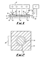
- the apparatus comprising a controller C for enabling the exposure of a surface portion of a layer 10 of particulate material to radiation, for example infra-red radiation provided by a radiation source 12, the controller C being arranged to control the variation of radiation absorption across the surface portion.
- radiation for example infra-red radiation provided by a radiation source 12
- Fig. 1 illustrates an apparatus, not claimed, for sintering particulate material in which an obscurer 14 (i.e. a mask) is provided for selectively obscuring the radiation provided by the source 12 on the surface portion of the layer 10 to thereby vary the intensity of the radiation incident on the surface portion of the layer 10.
- the obscurer 14 comprises a radiation transmissive substrate 16, such as a glass plate, which carries a varying amount of radiation reflective material 18, such as aluminium oxide.
- the amount and pattern of material 18 deposited on the substrate may be varied to selectively vary the intensity of radiation incident on the surface portion of the layer 10, as will be described hereinafter.
- the surface portion of the layer 10 is logically divided by the obscurer 14 into a number of areas including a combination portion 20, which is to be exposed to radiation to combine the particulate material, and a non-combination portion 22 which is to be shielded, or at least substantially shielded, from radiation to prevent combination of the particulate material by sintering.
- Full shielding of the non-combination portion 22 is not essential, provided that the intensity of radiation transmitted to the non-combination portion 22 is such that the particulate material is not heated to its sintering temperature. In some circumstances, transmission of low intensity radiation onto the non-combination portion 22 to heat the material can be desirable and can result in improved accuracy of the finished component. This is because heating material in the non-combination portion 22 reduces the thermal gradient between the material in the combination portion 20 and the non-combination portion 22.
- the combination portion 20 is logically divided by the obscurer 14 into a central portion 24 and an edge portion 26, and reflective material 18 is deposited onto the substrate 16 such that a greater amount of the material 18 is provided on the central portion 24 than on the edge portion 26 where no reflective material 18 may be provided. Consequently, the intensity of radiation provided across the surface of the combination portion 20 increases from a minimum value at the central portion 24 to a maximum value at the edge portion 26 where the surface of the layer 10 of particulate material is fully exposed to radiation provided by the radiation source 12.
- the layer of reflective material is schematically illustrated in Fig. 1 .
- the variation of thickness of the layer in the figure does not illustrate a variation of thickness of the layer in practice but illustrates a variation in the amount of the material. Where the layer is thick in the figure, in practice there will be a large amount of the material present.
- combination portion 20 has been shown to have only one edge portion 26 such that the central portion 24 is located at the centre of the combination portion 20, it should be appreciated that the combination portion 20 may for example be of annular configuration such that the central portion 24 is bounded on two sides by edge portions 26. Moreover, it is not essential that the central portion 24 is located at the centre of the surface portion of the layer 10 of particulate material.
- the controller C is arranged to control a motor 28 for moving the obscurer 16 from an obscuring position in which it overlies the layer 10, as shown in Fig. 1 , to a non-obscuring position in which it does not overly the layer 10.
- the controller C is also arranged to control a deposition device, such as a printing head 30, for depositing the reflective material 18 onto the substrate 16.
- the controller C controls the amount of material 18 deposited by the head 30 onto each part of the substrate 16.
- the head 30 remains stationary and deposits reflective material 18 onto the substrate 16 as the motor 28 moves the substrate 16 past the head 30.
- the substrate 16 may remain stationary, overlying the layer 10, and the motor 28 may move the printing head 30 over the substrate 16 to deposit reflective material 18 thereon.
- the reflective material 18 is contemporaneously printed onto the substrate 16 during operation of the apparatus.
- the amount of material 18 printed onto the substrate 16 by the head 30 may be varied by the controller C according to the surface temperature of the layer 10.
- the surface temperature of the layer 10 may be measured by a temperature measuring device, such as, for example, a pyrometer P or a thermal imaging camera, and surface temperature measurements are communicated in real time to the controller C.
- a wiping arrangement (not shown) may be provided for removing reflective material 18 from the substrate 16, so that it can be re-used. Different amounts of material 18 can be deposited onto the substrate 16, in dependence on the desired radiation intensity profile at the substrate surface.
- the reflective material 18 may be pre-printed onto the substrate 16 prior to operation of the apparatus and the same pre-printed substrate 16, or a number of pre-printed substrates 16, may be used, one for each layer 10 of particulate material. In this case, measurement of the surface temperature using pyrometer P may not be needed.
- the use of a plurality of pre-printed substrates 16 is particularly advantageous when there is a need to produce a large quantity of the same component since it reduces the time taken to sinter each layer of material and hence produce the prototype component, increases repeatability and leads to a reduction in the cost of producing the components.
- the apparatus may be operable to utilise a plurality of pre-printed substrates 16, or to contemporaneously print different amounts of reflective material 18 onto the same substrate 16, and to use these to expose the same layer 10 of material to different radiation intensity profiles in multiple exposure steps.
- Fig. 3 illustrates an apparatus, not claimed, for combining particulate material, in which corresponding elements are given corresponding reference numerals.
- the apparatus of Fig. 3 is similar to that shown in Fig. 1 , except that instead of the reflective material 18 being deposited onto a substrate 16, the reflective material 18 is deposited, using the printing head 30, directly onto the surface portion of the layer 10 of particulate material.
- the printing head 30 is again controlled by the controller C which controls both the movement of the head 30 across the surface of the layer 10 and the rate of deposition of reflective material 18 onto the layer 10.
- real time measurement of the surface temperature of the layer 10 may be carried out using a temperature measurement device, for example, a pyrometer P or thermal imaging camera, the temperature measurement being used by the controller C to determine the amount of reflective material 18 to be printed by the head 30 onto the surface portion of the layer 10.
- the layer of reflective material is schematically illustrated in Fig. 3 .
- the variation of thickness of the layer in the figure does not illustrate a variation of thickness of the layer in practice but illustrates a variation in the amount of the material. Where the layer is thick in the figure, in practice there will be a large amount of the material present.
- Fig. 4 illustrates an apparatus, not claimed, for combining particulate material which is similar to the apparatus illustrated in Figs. 1 and 3 and in which corresponding elements are given corresponding reference numerals.
- the controller C is arranged to selectively redirect the radiation provided by the source 12 and thereby vary the radiation intensity incident across the surface portion of the layer 10. Selective redirection of the radiation is achieved by controlling, using the controller C, a plurality of mirrors 34 which form a Digital Mirror Device (DMD) 36.
- DMD Digital Mirror Device
- Each mirror 34 is adjustable by the controller to an operative position, in which radiation is fully redirected onto the surface portion of the layer 10, or to an inoperative position in which radiation is fully redirected away from the surface portion.
- the surface portion of the layer 10 can be effectively divided into an array of segments, as discussed hereinafter, and the intensity of the radiation incident on each segment can be varied, according to a bitmap image, by selectively varying the frequencies at which individual mirrors 34 are moved between the operative and inoperative positions.
- a temperature measurement device such as a pyrometer P
- the controller C in response to instantaneous temperature variations across the surface portion of the layer 10.
- Fig. 5 illustrates an apparatus according to various embodiments of the present invention for combining particulate material which is similar to the apparatus described above and in which corresponding elements have been given corresponding reference numerals.
- the apparatus of Fig. 5 is most similar to the apparatus of Fig. 3 in that material is deposited directly onto the surface portion of the layer 10 of particulate material.
- the material is a radiation absorbent material 50, for example a material such as carbon black in powder form.
- radiation provided by the radiation source 12 is absorbed by the radiation absorbent material 50 where it is present on the surface, causing the radiation absorbent material 50 to heat up.
- Heat from the radiation absorbent material 50 is radiated to the underlying particulate material raising the temperature of individual particles of the particulate material. As the particles are heated to a temperature approaching their melting temperature, they neck and coalesce with adjacent heated particles. As the temperature subsequently decreases, the particles form a coherent mass of combined particulate material.
- a radiation absorbent material 50 directly onto the surface portion of the layer 10 enables the radiation absorptive properties of the particulate material to be varied and carefully controlled, as desired.
- varying the amount of the radiation absorbent material 50 on the surface enables the variation of the radiation absorptive properties of the surface portion of the underlying layer 10 of particulate material.
- a greater amount of the radiation provided by the radiation source 12 is absorbed. This provides for a greater amount of heat transfer to the underlying particulate material thereby heating it to a higher temperature and causing it to combine more rapidly.
- there is lower absorbent material 50 there is lower radiation absorption and hence less heat transfer to the underlying particulate material, causing it to combine at a slower rate.
- the layer of radiation absorbent material 50 is schematically illustrated in Fig. 5 .
- the variation of thickness of the layer in the figure does not illustrate a variation of thickness of the layer in practice but illustrates a variation in the amount of the material. Where the layer is thick in the figure, in practice there will be a large amount of the material present.
- the amount of the radiation absorbent material 50 decreases from a maximum value at the edge portion 26 to a minimum value at the central portion 24.
- no radiation absorbent material 50 is provided on the surface portion of the layer 10 of the particulate material in the non-combination portion 22.
- the printing head 30 is operable to deposit desired amounts of the radiation absorbent material 50 onto the surface portion of the layer 10, and the movement of the printing head 30 and the amount of material 50 deposited by the head 30 is controlled by the controller C.
- the pyrometer P or a thermal imaging camera may be used to measure the surface temperature of the layer 10, the amount of radiation absorbent material 50 deposited being varied by the controller C in accordance with the temperature measurements.
- the applicant has appreciated that when the particulate material is combined by sintering at a slow rate, the combined material has good material properties, for example high strength, but has poor definition at the edge portion 26.
- the poor edge definition arises because as the particulate material combines, there is some shrinkage which causes unwanted movement of uncombined particulate material from the non-combination portion 22 towards the combination portion 20.
- the particulate material is combined by sintering at a rapid rate, the combined material has inferior material properties, but has good edge definition since the particulate material in the edge portion 26 is rapidly combined and locked in position, thereby minimising unwanted movement of surrounding uncombined particulate material.
- One method by which this can be achieved is to use the apparatus according to the various embodiments of the invention described above to provide for greater absorption of radiation at the edge portion 26 than over the remainder of the combination portion 20.
- This can be achieved by varying the intensity of the radiation incident on the selected surface portion of the layer 10 using the apparatus illustrated in Figs. 1 , 3 and 4 and not claimed, or by varying the absorption of the radiation across the selected surface portion by providing a variable amount of radiation absorbent material 50 across the surface portion.
- radiation is provided over the layer 10 in a single exposure step.
- a constant first amount of radiation absorbent material 50 is provided over the combination portion 20, and radiation is then provided over the layer 10, using the radiation source 12, to cause the underlying particulate material in the combination portion 20 to combine.
- the first amount of radiation absorbent material 50 is selected to be a relatively low amount so that the underlying particulate material combines at a slow rate and has good material properties.
- the particulate material After the particulate material has been combined, further particulate material is added to the layer 10 at the edge portion 26 where there will have been shrinkage.
- a second amount of the same radiation absorbent material 50 which is greater than the first amount, is then provided over the edge portion 26, and radiation is again provided over the layer 10 using the radiation source 12.
- the second amount of material is selected to be a relatively high amount so that the underlying particulate material is caused to combine at a rapid rate. Due to the increased amount of radiation absorbent material 50 present at the edge portion 26, and hence the rapid combination of the underlying particulate material, material shrinkage is minimised thus providing the resultant layer 10 of combined material with good definition at the edge portion 26.
- a constant amount of a first radiation absorbent material 50 having a first natural radiation absorbency is provided over the combination portion 20, and radiation provided over the layer 10, using the radiation source 12, to cause the underlying particulate material in the combination portion 20 to combine.
- the first radiation absorbent material 50 is selected to have a low natural radiation absorbency so that a relatively low amount of the radiation is absorbed and so that the underlying particulate material combines at a slow rate and has good material properties.
- a second different radiation absorbent material 50 having a second natural radiation absorbency, is then provided over the edge portion 26, and radiation is again provided over the layer 10 using the radiation source 12.
- the second radiation absorbent material 50 is selected to have a high natural radiation absorbency, which is higher than the absorbency of the first radiation absorbent material 50, so that a high amount of the radiation is absorbed and so that the underlying particulate material in the edge portion 26 combines at a rapid rate.
- a fist radiation absorbent material 50 capable of absorbing a first wavelength of radiation is provided over the combination portion 20, and radiation of a first wavelength is then provided over the layer 10, using the radiation source 12, to cause the underlying particulate material in the combination portion 20 to combine.
- a second radiation absorbent material 50 capable of absorbing a second different wavelength of radiation, is then provided over the edge portion 26, and radiation of a second wavelength is provided over the layer 10 using the radiation source 12.
- the radiation at the first wavelength may be selected to have a relatively low intensity so that the first radiation absorbent material 50 is heated at a slow rate thereby causing the underlying particulate material to combine at a slow rate.
- the radiation at the second wavelength may selected to have a relatively high intensity so that the second radiation absorbent material 50 is heated rapidly thereby causing the underlying particulate material to combine at a rapid rate.
- a greater amount of the second radiation absorbent material 50 than the first radiation absorbent material 50 may be provided, as described above with reference to the first method, and the radiation of the first and second wavelengths provided by the radiation source 12 selected to have the same intensity.
- the second radiation absorbent material 50 may be selected to have a higher natural radiation absorbency than the first radiation absorbent material 50, as described above with reference to the second method, and the radiation of the first and second wavelengths provided by the radiation source 12 selected to have the same intensity.
- the third method could be adapted so that the first and second radiation absorbent materials 50 are simultaneously applied to the surface of the layer of particulate material, and the radiation of the first and second wavelengths provided in separate steps.
- first, second and third methods described above could be modified so that the particulate material at the edge portion 26 of the layer 10 is initially caused to combine at a rapid rate to lock the edge portion 26, and the particulate material in the remainder of the combination portion 20 is subsequently caused to combine at a slow rate to provide the desired material properties.
- the apparatus allows the surface portion of the layer 10 of particulate material to be logically divided into an array of segments 32.
- the controller can control the amount of radiation absorption on each segment 32 independently and a bitmap image can be used to specify the amount of radiation that should be absorbed at the surface portion.
- the greyscale of each segment 32 of the bitmap image is individually adjustable, and in the case of the apparatus illustrated in Figs. 1 and 3 and not claimed, the amount of reflective material 18 deposited onto each segment of the substrate 16 or surface portion of the layer 10 is individually adjustable, according to the bitmap image, to provide any desired radiation intensity profile over the surface portion of the layer 10.
- the mirrors 34 are adjusted to vary the intensity of radiation incident on each segment 32 of the array.
- the amount of radiation absorbent material 50 deposited onto each segment of the surface portion of the layer 10 is individually adjustable, according to the bitmap image, to provide any desired radiation absorption profile over the surface portion of the layer 10.
- a first amount of reflective material 18 has been deposited by printing head 30 onto the segments 32 defining the central portion 24 of the combination portion 20. Accordingly, a first intensity of radiation, which is less than the maximum intensity, is incident on the surface portion of the layer 10 located beneath these segments 32. The first intensity of radiation is sufficiently high to raise the temperature of the particulate material to cause it to combine.
- No reflective material 18 has been provided on the segments 32 which define the edge portion 26 of the combination portion 20, thereby allowing a maximum intensity of radiation to reach the surface portion of the layer 10 located beneath these segments 32.
- the maximum intensity of radiation causes the particulate material located beneath the segments 32 defining the edge portion 26 to combine more quickly than particulate material in the central portion 24.
- a sufficient amount of material 18 may be provided to prevent transmission of any radiation to the surface portion of the layer 10 located beneath these segments 32. Consequently, the particulate material located beneath these segments 32 does not combine.
- the layer of reflective material is schematically illustrated in Fig. 6b .
- the variation of thickness of the layer in the figure does not illustrate a variation of thickness of the layer in practice but illustrates a variation in the amount of the material. Where the layer is thick in the figure, in practice there will be a large amount of the material present.
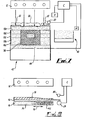
- FIG. 7 there is shown a diagrammatic illustration of the apparatus of Fig. 3 , not claimed, being used to form a three dimensional object 38. Again, elements of the apparatus which have been referred to above are given corresponding reference numerals.
- the apparatus is used to form a three dimensional object 38 by combining a plurality of layers 10a to 10e of particulate material.
- a supply of particulate material for example Nylon powder, is provided in a supply tank 40 and the controller C is arranged to control a motor M which can move particulate material from the tank 40 into a building device 42, which includes a vertically movable platform 44. Movement of the platform 44 is controlled by the controller C, such that the platform 44 is moved vertically downwards in discrete steps after each layer 10 has been formed.
- the controller C actuates the motor M to provide a first layer 10a of particulate material on the platform 44.
- the controller C then actuates the printing head 30 to deposit a desired pattern of reflective material 18 onto the surface portion of the layer 10 of material.
- the reflective material 18 may be deposited by the printing head 30 onto a substrate 16, as previously discussed, or the intensity incident at the surface may be controlled using digital mirrors.
- the controller C then activates the radiation source 12 to provide radiation over a selected surface portion of the layer 10, as defined by the reflective material 18. As shown in Fig. 7 , radiation is provided with varying intensity across the combination portion 20 and the material in this portion is combined.
- the reflective material 18 prevents, or at least substantially prevents, transmission of radiation to the surface portion of the material in the non-combination portion 22 where the material is not combined and remains in particulate form. The varying amount of reflective material 18 thus provides for variable intensity radiation across the combination portion 20 of the layer 10.
- the controller C deactivates the radiation source 12 and lowers the platform 44 by a distance approximately equivalent to the desired layer thickness.
- the controller C then actuates the motor M to provide a second layer 10b of particulate material overlying the first layer 10a including a previously combined portion of material.
- the controller C then actuates the printing head 30 to deposit reflective material 18 onto the surface portion of the second layer 10b.
- the amount and pattern of reflective material 18 deposited onto the surface portion of the second layer 10b may be the same as that provided on the first layer 10a, or may be different, for example in response to design or surface temperature measurements carried out using the pyrometer P.
- the controller C then activates the radiation source 12 to provide radiation across the surface portion of the second layer 10b, the reflective material 18 providing for variable intensity radiation across the surface portion.
- the material in the combination portion 20 of the second layer 10b is thus caused to combine, and also to combine with the previously combined portion of material in the first layer 10a.
- the adjacent layers 10a, 10b are thus combined to form part of a coherent object 38.
- the controller C continues to operate in this manner to provide further layers 10c to 10e of particulate material and combine them, until formation of the object 38 has been completed. Once the coherent object 38 has been formed, the platform 44 is raised by the controller C to eject the combined object 38 and any remaining uncombined particulate material surrounding the object 38 from the device 42.
- the apparatus may be used to form a three dimensional object 38.
- Fig. 8 illustrates use of the apparatus of Fig. 1 , not claimed, to combine different particulate materials P1 and P2 which are located adjacent to each other in a layer 10.
- the material P1 for example copper
- the material P2 may have a lower melting point than the material P2, for example steel, and may therefore combine by sintering at a lower temperature.
- the concentration of material P2 decreases from right to left across a transition gradient region 19.
- the concentration of material P1 decreases from left to right across the transition gradient region 19.
- the substrate 16 may be provided with a high amount of reflective material 18 on the portion overlying the material P1 of the layer 10, a low amount of reflective material on the portion overlying the material P2 and an amount of reflective material over the gradient region 19 that decreases from left to right in the figure.
- the materials P1 and P2 are heated to different temperatures using a fixed intensity radiation source 12 and are simultaneously combined to form a coherent layer.
- the layer of reflective material 18 is schematically illustrated in Fig. 8 .
- the variation of thickness of the layer in the figure does not illustrate a variation of thickness of the layer in practice but illustrates a variation in the amount of the material. Where the layer is thick in the figure, in practice there will be a large amount of the material present
- Fig. 1 Whilst the apparatus illustrated in Fig. 1 has been described for use in combining the dissimilar particulate materials P1 and P2, it will be readily appreciated that the apparatus illustrated in Fig. 3 in which reflective material 18 is printed directly onto the surface portion of the layer 10, the apparatus illustrated in Fig. 4 which uses mirrors 34 to selectively redirect radiation, or the apparatus according to various embodiments of the present invention in which radiation absorbent material 50 is printed directly onto the surface portion of the layer 10, could alternatively be used.
- a material such as carbon black may be used for this purpose.
- particulate materials such as ceramic filler powder, may be added to the particulate material to improve the material properties of the resultant component.
- infra-red radiation radiation other than infra-red may be used, provided that it is able to elevate the particulate material to a temperature at which it combines by sintering.
- the source of radiation may be of any suitable type, for example, LEDs, a scanning laser or a halogen source.
- the particulate material that is combined by the above described embodiments may be any suitable material, such as a metal, ceramic etc.
- a device other than a motor M may be used to move particulate material from the supply tank 40 to the combination device 42.
- the combination device 42 may be of a different configuration to that shown. Any number of different types of particulate material may be provided in a layer 10. Alternatively, different types of particulate material may be provided in adjacent layers.
- Reflective material 18 may be deposited onto a lower surface of the substrate 16 rather than an upper surface, as illustrated. Different materials may be used for the reflective material 18 and the substrate 16. Any suitable material may be used for the radiation absorbent material 50. For example, a liquid suspension and/or a gas, for example carbon dioxide, could be employed instead of a powder material.
- the digital mirror device described in relation to Fig. 4 could be replaced by a series of diffractive optics, one for each layer.
Landscapes
- Engineering & Computer Science (AREA)
- Mechanical Engineering (AREA)
- Physics & Mathematics (AREA)
- Optics & Photonics (AREA)
- Chemical & Material Sciences (AREA)
- Materials Engineering (AREA)
- Manufacturing & Machinery (AREA)
- Manufacture And Refinement Of Metals (AREA)
- Physical Or Chemical Processes And Apparatus (AREA)
Claims (16)
- Procédé de frittage sélectif de matériau particulaire, comprenant les étapes suivantes :(i) prendre une couche de matériau particulaire (10) ;(ii) faire varier l'absorption de rayonnement reçu à travers une partie choisie (20) de surface de la couche (10), afin de fritter une partie du matériau de la couche (10) ;(iii) prendre une couche supplémentaire de matériau particulaire (10) recouvrant la couche précédente de matériau particulaire (10), qui comprend la partie préalablement frittée de matériau ;(iv) faire varier l'absorption du rayonnement reçu à travers une partie choisie (20) de la surface de la couche supplémentaire (10), afin de fritter une partie supplémentaire du matériau au sein de la couche supplémentaire de recouvrement, et de fritter ladite partie supplémentaire avec la partie préalablement frittée de matériau dans la couche précédente ;(v) répéter successivement les étapes (iii) et (iv), afin d'obtenir un objet tridimensionnel ;caractérisé en ce que la variation de l'absorption du rayonnement des étapes (ii) et (iv) est possible par placement d'une certaine quantité de matériau (50) absorbant du rayonnement sur la partie choisie (20) de surface de la couche (10), et de la couche supplémentaire (10) respectivement.
- Procédé selon la revendication 1, où les étapes (ii) et (iv) comprennent l'obtention d'un premier niveau d'absorption de rayonnement sur une première zone de la partie choisie (20) et un deuxième niveau différent d'absorption de rayonnement sur une deuxième zone de la partie choisie (20), contiguë à la première zone.
- Procédé selon la revendication 2, où les étapes (ii) et (iv) comprennent l'obtention d'un troisième niveau différent d'absorption de rayonnement sur une troisième zone de la partie choisie (20), contiguë à la deuxième zone.
- Procédé selon la revendication 2 ou 3, dans lequel l'étape (i) comprend le fait de prendre un premier matériau particulaire dans la première zone et un deuxième matériau particulaire dans la deuxième zone de la couche.
- Procédé selon la revendication 1, comprenant le rayonnement sur une zone (20) de combinaison, dans laquelle on doit fritter du matériau particulaire, cette zone de combinaison comprenant une partie centrale (24) et une partie de bord (26), et où les étapes (ii) et (iv) comprennent le fait de prévoir une absorption de rayonnement plus importante au niveau de la partie de bord (26) qu'au niveau de la partie centrale (24).
- Procédé selon la revendication 5, où l'absorption du rayonnement augmente à partir d'une valeur minimale au niveau de la partie centrale (24) jusqu'à une valeur maximale au niveau de la partie de bord (26).
- Procédé selon la revendication 5 ou 6, où l'étape de rayonnement comprend le rayonnement sur une zone (22) d'absence de combinaison, contiguë et extérieure par rapport à la zone (20) de combinaison, et où les étapes (ii) et (iv) comprennent le fait de faire varier l'absorption du rayonnement émis, si bien que l'absorption du rayonnement sur la zone (22) d'absence de combinaison est moins importante que l'absorption du rayonnement sur la partie de bord (26) de la zone (20) de combinaison.
- Procédé selon la revendication 7, où l'absorption du rayonnement sur la zone (22) d'absence de combinaison est moins importante que l'absorption du rayonnement sur la partie centrale (24) de la zone (20) de combinaison.
- Procédé selon l'une quelconque des revendications précédentes, où les étapes (ii) et (iv) comprennent le fait de diviser de manière logique la surface de la partie choisie (20) en un ensemble de segments, et l'obtention d'un niveau différent d'absorption du rayonnement sur différents segments de l'ensemble.
- Procédé selon la revendication 9, où les étapes (ii) et (iv) comprennent la création d'une image matricielle qui divise la surface en une pluralité de segments.
- Procédé selon l'une quelconque des revendications précédentes, où les étapes (ii) et (iv) comprennent le fait de prendre un matériau (50) absorbant du rayonnement pour absorber une première longueur d'onde de rayonnement sur une première zone de la partie choisie (20) de surface, et le fait de prendre un matériau (50) absorbant du rayonnement pour absorber une deuxième longueur d'onde différente de rayonnement sur une deuxième zone de la partie choisie (20) de surface.
- Procédé selon la revendication 11, où le procédé comprend un rayonnement de première longueur d'onde sur la couche de matériau particulaire (10), permettant de combiner le matériau dans la première zone, et un rayonnement de deuxième longueur d'onde sur la couche de matériau particulaire (10), permettant de combiner le matériau dans la deuxième zone.
- Procédé selon l'une quelconque des revendications précédentes, où les étapes (ii) et (iv) impliquent des quantités variables de matériau (50) absorbant du rayonnement sur la partie choisie (20) de surface de la couche (10), par impression de matériau (50) absorbant du rayonnement sur la partie choisie (20) de surface.
- Appareil de frittage de matériau particulaire, l'appareil comprenant une tête d'impression (30) et un contrôleur permettant l'exposition d'une partie de surface d'une couche de matériau particulaire (10) à du rayonnement, caractérisé en ce que la tête d'impression contient du matériau absorbant du rayonnement et en ce que le contrôleur est conçu pour réguler la variation d'absorption de rayonnement à travers ladite partie de surface en commandant le dépôt d'une certaine quantité de matériau (50) absorbant du rayonnement sur la couche de matériau particulaire (10) par la tête d'impression (30).
- Appareil selon la revendication 14, dans lequel le contrôleur est sensible aux variations de température à travers la partie de surface, celui-ci étant conçu pour réguler le dépôt d'une certaine quantité de matériau (50) absorbant du rayonnement en réponse à la variation de température.
- Appareil selon la revendication 14, dans lequel le contrôleur est conçu pour réguler le dépôt de différents matériau (50) absorbant du rayonnement, à même d'absorber différentes longueurs d'onde de rayonnement directement sur la partie de surface de la couche (10), et pour permettre l'exposition de la partie de surface au rayonnement de différentes longueurs d'onde.
Applications Claiming Priority (2)
| Application Number | Priority Date | Filing Date | Title |
|---|---|---|---|
| GBGB0317387.9A GB0317387D0 (en) | 2003-07-25 | 2003-07-25 | Method and apparatus for combining particulate material |
| PCT/GB2004/003142 WO2005011959A1 (fr) | 2003-07-25 | 2004-07-20 | Procede et appareil pour combiner un materiau particulaire |
Publications (3)
| Publication Number | Publication Date |
|---|---|
| EP1648686A1 EP1648686A1 (fr) | 2006-04-26 |
| EP1648686B1 true EP1648686B1 (fr) | 2009-12-02 |
| EP1648686B2 EP1648686B2 (fr) | 2015-06-24 |
Family
ID=27772625
Family Applications (1)
| Application Number | Title | Priority Date | Filing Date |
|---|---|---|---|
| EP04743477.4A Active EP1648686B2 (fr) | 2003-07-25 | 2004-07-20 | Procede et appareil pour frittage selectif d'un materiau particulaire |
Country Status (7)
| Country | Link |
|---|---|
| US (2) | US7879282B2 (fr) |
| EP (1) | EP1648686B2 (fr) |
| JP (1) | JP4691680B2 (fr) |
| AT (1) | ATE450361T1 (fr) |
| DE (1) | DE602004024403D1 (fr) |
| GB (1) | GB0317387D0 (fr) |
| WO (1) | WO2005011959A1 (fr) |
Cited By (14)
| Publication number | Priority date | Publication date | Assignee | Title |
|---|---|---|---|---|
| DE102013004940A1 (de) | 2012-10-15 | 2014-04-17 | Voxeljet Ag | Verfahren und Vorrichtung zum Herstellen von dreidimensionalen Modellen mit temperiertem Druckkopf |
| DE102013019716A1 (de) | 2013-11-27 | 2015-05-28 | Voxeljet Ag | 3D-Druckverfahren mit Schlicker |
| DE102015006533A1 (de) | 2014-12-22 | 2016-06-23 | Voxeljet Ag | Verfahren und Vorrichtung zum Herstellen von 3D-Formteilen mit Schichtaufbautechnik |
| WO2016122660A1 (fr) * | 2015-01-30 | 2016-08-04 | Hewlett-Packard Development Company, L.P. | Étalonnage d'agent |
| DE102015014964A1 (de) | 2015-11-20 | 2017-05-24 | Voxeljet Ag | Verfahren und Vorrichtung für 3D-Druck mit engem Wellenlängenspektrum |
| DE102015016464A1 (de) | 2015-12-21 | 2017-06-22 | Voxeljet Ag | Verfahren und Vorrichtung zum Herstellen von 3D-Formteilen mit Schichtaufbautechnik und steuerbarer Pulverwalze |
| EP3157737B1 (fr) | 2014-06-23 | 2018-07-18 | Covestro Deutschland AG | Utilisation de polyuréthane en poudre thermoplastique |
| WO2019015707A1 (fr) | 2017-07-21 | 2019-01-24 | Voxeljet Ag | Procédé et dispositif de fabrication de pièces façonnées en 3d à l'aide d'un convertisseur de spectre |
| WO2021008641A1 (fr) | 2019-07-17 | 2021-01-21 | Voxeljet Ag | Procédé pour produire des pièces moulées 3d dont les points d'image imprimés présentent des propriétés cibles variables |
| WO2021069003A1 (fr) | 2019-10-11 | 2021-04-15 | Voxeljet Ag | Procédé et dispositif pour la production de pièces façonnées en 3d à l'aide d'émetteurs de rayonnement à haute performance |
| WO2021098898A2 (fr) | 2019-11-18 | 2021-05-27 | Voxeljet Ag | Dispositif d'impression 3d ayant une géométrie d'espace occupé avantageuse |
| US11504906B2 (en) | 2017-05-09 | 2022-11-22 | Covestro Deutschland Ag | Method for producing products by means of additive manufacturing methods using reactive powders, and products thereof |
| US11679560B2 (en) | 2014-01-16 | 2023-06-20 | Hewlett-Packard Development Company, L.P. | Generating a three-dimensional object |
| US11767428B2 (en) | 2017-10-04 | 2023-09-26 | Arkema France | Thermoplastic powder composition and reinforced three-dimensional object produced by 3D printing of such a composition |
Families Citing this family (132)
| Publication number | Priority date | Publication date | Assignee | Title |
|---|---|---|---|---|
| EP1226019B1 (fr) | 1999-11-05 | 2004-03-03 | Z Corporation | Procedes pour impression tridimensionnelle |
| EP1459871B1 (fr) * | 2003-03-15 | 2011-04-06 | Evonik Degussa GmbH | Procédé et dispositif pour la fabrication des objets tridimensionnels au moyen de radiation à micro-ondes et pièce moulée ainsi obtenue |
| DE102004012682A1 (de) * | 2004-03-16 | 2005-10-06 | Degussa Ag | Verfahren zur Herstellung von dreidimensionalen Objekten mittels Lasertechnik und Auftragen eines Absorbers per Inkjet-Verfahren |
| DE102004020452A1 (de) | 2004-04-27 | 2005-12-01 | Degussa Ag | Verfahren zur Herstellung von dreidimensionalen Objekten mittels elektromagnetischer Strahlung und Auftragen eines Absorbers per Inkjet-Verfahren |
| GB2422344B (en) * | 2005-01-24 | 2008-08-20 | Univ Montfort | Rapid prototyping method using infrared sintering |
| US20070241482A1 (en) * | 2006-04-06 | 2007-10-18 | Z Corporation | Production of three-dimensional objects by use of electromagnetic radiation |
| EP2089215B1 (fr) | 2006-12-08 | 2015-02-18 | 3D Systems Incorporated | Système de matériaux d'impression tridimensionnelle |
| EP2109528B1 (fr) | 2007-01-10 | 2017-03-15 | 3D Systems Incorporated | Système de matériau d'impression tridimensionnel avec une couleur, une performance de l'article et une facilité d'utilisation améliorées et procédé utilisant ce système |
| US7968626B2 (en) | 2007-02-22 | 2011-06-28 | Z Corporation | Three dimensional printing material system and method using plasticizer-assisted sintering |
| DE102007024469B4 (de) | 2007-05-25 | 2009-04-23 | Eos Gmbh Electro Optical Systems | Verfahren zum schichtweisen Herstellen eines dreidimensionalen Objekts |
| WO2009084991A1 (fr) | 2008-01-03 | 2009-07-09 | Arcam Ab | Procédé et appareil de production d'objets en trois dimensions |
| KR101596432B1 (ko) * | 2009-07-15 | 2016-02-22 | 아르켐 에이비 | 삼차원 물체의 제작 방법 및 장치 |
| CN103338880B (zh) | 2011-01-28 | 2015-04-22 | 阿卡姆股份有限公司 | 三维物体生产方法 |
| GB2493398B (en) * | 2011-08-05 | 2016-07-27 | Univ Loughborough | Methods and apparatus for selectively combining particulate material |
| EP2797730B2 (fr) | 2011-12-28 | 2020-03-04 | Arcam Ab | Procédé et appareil de détection de défauts pour une fabrication de forme libre |
| US10189086B2 (en) | 2011-12-28 | 2019-01-29 | Arcam Ab | Method and apparatus for manufacturing porous three-dimensional articles |
| JP6101707B2 (ja) | 2011-12-28 | 2017-03-22 | ア−カム アーベー | 積層造形法による三次元物品の解像度を向上させるための方法および装置 |
| DE112012006355B4 (de) | 2012-05-11 | 2023-05-11 | Arcam Ab | Pulververteilung bei additiver Herstellung |
| US9776282B2 (en) | 2012-10-08 | 2017-10-03 | Siemens Energy, Inc. | Laser additive manufacture of three-dimensional components containing multiple materials formed as integrated systems |
| EP2916980B1 (fr) | 2012-11-06 | 2016-06-01 | Arcam Ab | Prétraitement de poudres pour fabrication additive |
| US10023739B2 (en) | 2012-11-21 | 2018-07-17 | Stratasys, Inc. | Semi-crystalline build materials |
| US10144828B2 (en) | 2012-11-21 | 2018-12-04 | Stratasys, Inc. | Semi-crystalline build materials |
| US9925714B2 (en) | 2012-11-21 | 2018-03-27 | Stratasys, Inc. | Method for printing three-dimensional items wtih semi-crystalline build materials |
| US9505172B2 (en) | 2012-12-17 | 2016-11-29 | Arcam Ab | Method and apparatus for additive manufacturing |
| US9718129B2 (en) | 2012-12-17 | 2017-08-01 | Arcam Ab | Additive manufacturing method and apparatus |
| US9550207B2 (en) | 2013-04-18 | 2017-01-24 | Arcam Ab | Method and apparatus for additive manufacturing |
| US9676031B2 (en) | 2013-04-23 | 2017-06-13 | Arcam Ab | Method and apparatus for forming a three-dimensional article |
| US9415443B2 (en) | 2013-05-23 | 2016-08-16 | Arcam Ab | Method and apparatus for additive manufacturing |
| US9468973B2 (en) | 2013-06-28 | 2016-10-18 | Arcam Ab | Method and apparatus for additive manufacturing |
| US9505057B2 (en) | 2013-09-06 | 2016-11-29 | Arcam Ab | Powder distribution in additive manufacturing of three-dimensional articles |
| US9676033B2 (en) | 2013-09-20 | 2017-06-13 | Arcam Ab | Method for additive manufacturing |
| US10434572B2 (en) | 2013-12-19 | 2019-10-08 | Arcam Ab | Method for additive manufacturing |
| US9802253B2 (en) | 2013-12-16 | 2017-10-31 | Arcam Ab | Additive manufacturing of three-dimensional articles |
| US10130993B2 (en) | 2013-12-18 | 2018-11-20 | Arcam Ab | Additive manufacturing of three-dimensional articles |
| US9789563B2 (en) | 2013-12-20 | 2017-10-17 | Arcam Ab | Method for additive manufacturing |
| MX2016009288A (es) | 2014-01-16 | 2016-10-07 | Hewlett Packard Development Co Lp | Generar objetos tridimensionales. |
| JP6570542B2 (ja) | 2014-01-16 | 2019-09-04 | ヒューレット−パッカード デベロップメント カンパニー エル.ピー.Hewlett‐Packard Development Company, L.P. | 三次元物体の生成 |
| WO2015106838A1 (fr) | 2014-01-16 | 2015-07-23 | Hewlett-Packard Development Company, L.P. | Génération d'un objet tridimensionnel |
| GB2538408B (en) * | 2014-01-16 | 2020-06-03 | Hewlett Packard Development Co | Generating three-dimensional objects |
| US9789541B2 (en) | 2014-03-07 | 2017-10-17 | Arcam Ab | Method for additive manufacturing of three-dimensional articles |
| EP2918359A1 (fr) | 2014-03-11 | 2015-09-16 | BAE Systems PLC | Frittage de matériau particulaire |
| GB201404247D0 (en) * | 2014-03-11 | 2014-04-23 | Bae Systems Plc | Sintering particulate material |
| WO2015136278A1 (fr) | 2014-03-11 | 2015-09-17 | Bae Systems Plc | Frittage d'une matière particulaire |
| US10293593B2 (en) | 2014-03-11 | 2019-05-21 | Bae Systems Plc | Forming a three dimensional object |
| EP2918394A1 (fr) | 2014-03-11 | 2015-09-16 | BAE Systems PLC | Frittage de matériau particulaire |
| US20150283613A1 (en) | 2014-04-02 | 2015-10-08 | Arcam Ab | Method for fusing a workpiece |
| WO2015167520A1 (fr) | 2014-04-30 | 2015-11-05 | Hewlett-Packard Development Company, L.P. | Modèle informatique et procédés d'impression en trois dimensions (3d) |
| WO2016010536A1 (fr) * | 2014-07-16 | 2016-01-21 | Hewlett-Packard Development Company, L.P. | Consolidation d'un substrat de matériau de construction destiné à la fabrication additive |
| US9347770B2 (en) | 2014-08-20 | 2016-05-24 | Arcam Ab | Energy beam size verification |
| US10386797B2 (en) * | 2014-09-16 | 2019-08-20 | 3D Systems, Inc. | Fracturing a shell of a three-dimensional object |
| WO2016048357A1 (fr) * | 2014-09-26 | 2016-03-31 | Hewlett-Packard Development Company, L.P. | Éclairage pour la fabrication additive |
| CN114474725A (zh) * | 2014-09-26 | 2022-05-13 | 惠普发展公司, 有限责任合伙企业 | 用于增材制造的光照 |
| US10730242B2 (en) | 2014-10-03 | 2020-08-04 | Hewlett-Packard Development Company, L.P. | Controlling temperature in an apparatus for generating a three-dimensional object |
| WO2016050319A1 (fr) * | 2014-10-03 | 2016-04-07 | Hewlett-Packard Development Company, L. P. | Commande de chauffage de surface |
| US10926326B2 (en) | 2014-10-05 | 2021-02-23 | Yazaki Corporation | 3D printers and feedstocks for 3D printers |
| WO2016060703A1 (fr) | 2014-10-14 | 2016-04-21 | 3D Forms, Inc. | Fabrication additive à l'aide de faisceaux gazeux chauffés et mis en forme |
| CN106794519B (zh) * | 2014-10-14 | 2019-05-28 | 西门子能源有限公司 | 形成为一体化体系的包含多种材料的三维部件的激光增材制造 |
| EP3233425B1 (fr) * | 2014-12-15 | 2021-03-31 | Hewlett-Packard Development Company, L.P. | Fabrication additive |
| US10786865B2 (en) | 2014-12-15 | 2020-09-29 | Arcam Ab | Method for additive manufacturing |
| US9406483B1 (en) | 2015-01-21 | 2016-08-02 | Arcam Ab | Method and device for characterizing an electron beam using an X-ray detector with a patterned aperture resolver and patterned aperture modulator |
| WO2016140670A1 (fr) * | 2015-03-05 | 2016-09-09 | Hewlett-Packard Development Company, L.P. | Production d'objets tridimensionnels |
| US11014161B2 (en) | 2015-04-21 | 2021-05-25 | Arcam Ab | Method for additive manufacturing |
| WO2016171724A1 (fr) | 2015-04-24 | 2016-10-27 | Hewlett-Packard Development Company, L.P. | Agent de détaillage pour impression en trois dimensions (3d) |
| KR20170100000A (ko) | 2015-04-30 | 2017-09-01 | 휴렛-팩커드 디벨롭먼트 컴퍼니, 엘.피. | 다중-구조의 3d 물체의 프린팅 |
| WO2016173668A1 (fr) | 2015-04-30 | 2016-11-03 | Hewlett-Packard Development Company, L.P. | Détection de défauts d'alignement pour un dispositif d'impression 3d |
| US10675812B2 (en) | 2015-04-30 | 2020-06-09 | Hewlett-Packard Development Company, L.P. | Three-dimensional (3D) printing |
| WO2017015241A1 (fr) * | 2015-07-18 | 2017-01-26 | Vulcanforms Inc. | Fabrication additive par fusion de matériau spatialement contrôlée |
| WO2017019102A1 (fr) * | 2015-07-30 | 2017-02-02 | Hewlett-Packard Development Company, L.P. | Production d'objets en trois dimensions |
| US10843415B1 (en) | 2015-08-07 | 2020-11-24 | University Of South Florida | Projection material processing system and associated method of use |
| US10807187B2 (en) | 2015-09-24 | 2020-10-20 | Arcam Ab | X-ray calibration standard object |
| US11571748B2 (en) | 2015-10-15 | 2023-02-07 | Arcam Ab | Method and apparatus for producing a three-dimensional article |
| US10525531B2 (en) | 2015-11-17 | 2020-01-07 | Arcam Ab | Additive manufacturing of three-dimensional articles |
| US10610930B2 (en) | 2015-11-18 | 2020-04-07 | Arcam Ab | Additive manufacturing of three-dimensional articles |
| JP6994295B2 (ja) * | 2015-12-17 | 2022-01-14 | セイコーエプソン株式会社 | 三次元造形物の製造方法および三次元造形物製造装置 |
| WO2017138915A1 (fr) * | 2016-02-08 | 2017-08-17 | Hewlett-Packard Development Company, L.P. | Régulation de température de couche de construction |
| JP2017141505A (ja) * | 2016-02-09 | 2017-08-17 | 株式会社ジェイテクト | 造形物の製造装置、及び製造方法 |
| US11247274B2 (en) | 2016-03-11 | 2022-02-15 | Arcam Ab | Method and apparatus for forming a three-dimensional article |
| CN109070467B (zh) * | 2016-04-04 | 2021-04-13 | 惠普发展公司,有限责任合伙企业 | 用于增材制造的防护特征的定义 |
| US20190061267A1 (en) * | 2016-05-12 | 2019-02-28 | Hewlett-Packard Development Company, L.P. | Thermal imaging device calibration |
| EP3429825B1 (fr) | 2016-05-12 | 2021-03-03 | Hewlett-Packard Development Company, L.P. | Correction de température par application d'un agent d'impression |
| US11179894B2 (en) | 2016-05-12 | 2021-11-23 | Hewlett-Packard Development Company, L.P. | Managing thermal contributions between layers during additive manufacturing |
| KR102182753B1 (ko) * | 2016-05-12 | 2020-11-26 | 휴렛-팩커드 디벨롭먼트 컴퍼니, 엘.피. | 3차원 물체 형성 기법 |
| WO2017197388A1 (fr) * | 2016-05-13 | 2017-11-16 | Board Of Regents, The University Of Texas System | Systèmes et procédés de fusion volumétrique en lit de poudre |
| US10549348B2 (en) | 2016-05-24 | 2020-02-04 | Arcam Ab | Method for additive manufacturing |
| US11325191B2 (en) | 2016-05-24 | 2022-05-10 | Arcam Ab | Method for additive manufacturing |
| US10525547B2 (en) | 2016-06-01 | 2020-01-07 | Arcam Ab | Additive manufacturing of three-dimensional articles |
| ES2906330T3 (es) | 2016-09-12 | 2022-04-18 | Covestro Deutschland Ag | Procedimiento de fabricación aditiva a base de polvo a baja temperatura |
| US11161296B2 (en) | 2016-09-26 | 2021-11-02 | Formlabs, Inc. | Techniques for reducing differential cure artifacts for additive fabrication and related systems and methods |
| US10792757B2 (en) | 2016-10-25 | 2020-10-06 | Arcam Ab | Method and apparatus for additive manufacturing |
| US20190315062A1 (en) | 2016-11-22 | 2019-10-17 | Covestro Deutschland Ag | Method and system for producing an article by layer-by-layer buildup in a stamping process |
| KR102477958B1 (ko) * | 2016-11-25 | 2022-12-19 | 코베스트로 도이칠란트 아게 | 적어도 부분적으로 코팅된 물품을 제조하는 방법 |
| US20200009769A1 (en) | 2016-12-14 | 2020-01-09 | Covestro Deutschland Ag | Method for producing a 3d printed, foam-filed object |
| US10987752B2 (en) | 2016-12-21 | 2021-04-27 | Arcam Ab | Additive manufacturing of three-dimensional articles |
| WO2018125630A1 (fr) * | 2016-12-29 | 2018-07-05 | 3D Systems, Inc. | Régulation de la température de poudres pour fabrication additive par modulation spatiale de la lumière |
| WO2018136048A1 (fr) | 2017-01-18 | 2018-07-26 | Hewlett-Packard Development Company, L.P. | Contrôle de déviants dans la fabrication additive |
| EP3388169B1 (fr) | 2017-04-11 | 2023-07-26 | Fundació Institut de Ciències Fotòniques | Procédé et système de production d'un objet tridimensionnel |
| CN110573325A (zh) * | 2017-04-21 | 2019-12-13 | 惠普发展公司,有限责任合伙企业 | 增材制造机器热流 |
| US11059123B2 (en) | 2017-04-28 | 2021-07-13 | Arcam Ab | Additive manufacturing of three-dimensional articles |
| US11911958B2 (en) | 2017-05-04 | 2024-02-27 | Stratasys, Inc. | Method and apparatus for additive manufacturing with preheat |
| US11292062B2 (en) | 2017-05-30 | 2022-04-05 | Arcam Ab | Method and device for producing three-dimensional objects |
| WO2018229095A1 (fr) | 2017-06-14 | 2018-12-20 | Covestro Deutschland Ag | Procédé de fabrication additif en utilisant des amines à des fins de post-durcissement |
| US11152556B2 (en) | 2017-07-29 | 2021-10-19 | Nanohmics, Inc. | Flexible and conformable thermoelectric compositions |
| US11185926B2 (en) | 2017-09-29 | 2021-11-30 | Arcam Ab | Method and apparatus for additive manufacturing |
| US10529070B2 (en) | 2017-11-10 | 2020-01-07 | Arcam Ab | Method and apparatus for detecting electron beam source filament wear |
| US10821721B2 (en) | 2017-11-27 | 2020-11-03 | Arcam Ab | Method for analysing a build layer |
| US11072117B2 (en) | 2017-11-27 | 2021-07-27 | Arcam Ab | Platform device |
| EP3725496A4 (fr) | 2017-12-13 | 2021-02-17 | Konica Minolta, Inc. | Méthode de production d'un objet moulé tridimensionnel, et matériau en poudre utilisé dans celle-ci |
| CN111465482A (zh) | 2017-12-19 | 2020-07-28 | 科思创德国股份有限公司 | 制造处理过的3d打印物件的方法 |
| WO2019121277A1 (fr) | 2017-12-20 | 2019-06-27 | Covestro Deutschland Ag | Procédé de fabrication additive faisant appel à de la poudre |
| CN111601716B (zh) | 2017-12-20 | 2022-07-08 | 科思创德国股份有限公司 | 粉末基增材制造法 |
| US11517975B2 (en) | 2017-12-22 | 2022-12-06 | Arcam Ab | Enhanced electron beam generation |
| WO2019146474A1 (fr) | 2018-01-29 | 2019-08-01 | コニカミノルタ株式会社 | Composition de résine pour moulage 3d, et article moulé en 3d ainsi que procédé de fabrication de celui-ci |
| US11458682B2 (en) | 2018-02-27 | 2022-10-04 | Arcam Ab | Compact build tank for an additive manufacturing apparatus |
| US11267051B2 (en) | 2018-02-27 | 2022-03-08 | Arcam Ab | Build tank for an additive manufacturing apparatus |
| US10875094B2 (en) | 2018-03-29 | 2020-12-29 | Vulcanforms Inc. | Additive manufacturing systems and methods |
| US11400519B2 (en) | 2018-03-29 | 2022-08-02 | Arcam Ab | Method and device for distributing powder material |
| DE102018108001A1 (de) | 2018-04-05 | 2019-10-10 | Lean Plastics Technologies GmbH | Verfahren und Vorrichtung zur Herstellung von kugelförmigen Polymerpartikeln und deren Verwendung |
| WO2019226170A1 (fr) * | 2018-05-25 | 2019-11-28 | Hewlett-Packard Development Company, L.P. | Fourniture de matériaux de construction sur la base de cartes thermiques théoriques |
| JP7139720B2 (ja) | 2018-06-27 | 2022-09-21 | 株式会社リコー | 造形物の製造方法、及び造形物の製造装置 |
| US11376795B1 (en) | 2018-09-21 | 2022-07-05 | University Of South Florida | Sintering monitoring method |
| FR3087198B1 (fr) | 2018-10-11 | 2021-11-19 | Arkema France | Poudre de polymere thermoplastique pour impression 3d a recyclabilite amelioree |
| CA3107856A1 (fr) | 2018-11-13 | 2020-05-22 | Covestro Intellectual Property Gmbh & Co. Kg | Procede de production d'un objet fabrique et traite de maniere additive |
| JP6730412B2 (ja) * | 2018-12-06 | 2020-07-29 | ヒューレット−パッカード デベロップメント カンパニー エル.ピー.Hewlett‐Packard Development Company, L.P. | 3次元物体の生成 |
| WO2020114963A1 (fr) | 2018-12-06 | 2020-06-11 | Covestro Deutschland Ag | Surfaces de film fonctionnalisées par impression 3d pour équiper des surfaces de pièces |
| WO2020127634A1 (fr) | 2018-12-20 | 2020-06-25 | Covestro Intellectual Property Gmbh & Co. Kg | Procédé d'application de poudre en couches pour fabriquer par impression 3d des pièces présentant des propriétés mécaniques améliorées |
| FR3093945B1 (fr) | 2019-03-18 | 2023-10-27 | Arkema France | Polyamides et copolyamides ignifuges pour impression 3d |
| US11926101B2 (en) | 2019-05-03 | 2024-03-12 | Hewlett-Packard Development Company, L.P. | Agent composition determination based on thermal values |
| DE102019007595A1 (de) | 2019-11-01 | 2021-05-06 | Voxeljet Ag | 3d-druckverfahren und damit hergestelltes formteil unter verwendung von ligninsulfat |
| WO2021175886A1 (fr) | 2020-03-06 | 2021-09-10 | Basf Se | Agents de fusion |
| EP4188972A1 (fr) | 2020-08-03 | 2023-06-07 | Basf Se | Poudre de frittage (sp) contenant un polyuréthane thermoplastique, un plastifiant et un additif organique |
| US11945155B2 (en) | 2020-09-21 | 2024-04-02 | Formlabs, Inc. | Techniques for reducing peel forces in additive fabrication and related systems and methods |
| EP4359462A1 (fr) | 2021-06-21 | 2024-05-01 | Basf Se | Poudre de frittage (sp) comprenant un polyuréthane thermoplastique |
Family Cites Families (38)
| Publication number | Priority date | Publication date | Assignee | Title |
|---|---|---|---|---|
| DE3702449A1 (de) | 1986-01-30 | 1987-08-06 | Electronic Instrumentation And | Vorrichtung zum regeln der uv-strahlung, die auf einen gegenstand trifft |
| EP0287657B2 (fr) * | 1986-10-17 | 1999-08-11 | Board Of Regents, The University Of Texas System | Procede et appareil de production de pieces par frittage selectif |
| US5296062A (en) * | 1986-10-17 | 1994-03-22 | The Board Of Regents, The University Of Texas System | Multiple material systems for selective beam sintering |
| US4752498A (en) | 1987-03-02 | 1988-06-21 | Fudim Efrem V | Method and apparatus for production of three-dimensional objects by photosolidification |
| EP0351413B1 (fr) * | 1987-03-02 | 1993-08-04 | FUDIM, Efrem V. | Procede et appareil pour la production d'objets tridimensionnels par photosolidification |
| US5182056A (en) | 1988-04-18 | 1993-01-26 | 3D Systems, Inc. | Stereolithography method and apparatus employing various penetration depths |
| US5014207A (en) * | 1989-04-21 | 1991-05-07 | E. I. Du Pont De Nemours And Company | Solid imaging system |
| US5204055A (en) * | 1989-12-08 | 1993-04-20 | Massachusetts Institute Of Technology | Three-dimensional printing techniques |
| JPH0571994A (ja) * | 1991-09-10 | 1993-03-23 | Sekisui Chem Co Ltd | 立体画像表示盤の製造方法 |
| ATE170008T1 (de) | 1991-10-02 | 1998-09-15 | Spectra Group Ltd Inc | Herstellung dreidimensionaler objekte |
| JP3166130B2 (ja) * | 1992-04-14 | 2001-05-14 | ソニー株式会社 | 光学的造形装置及び造形方法 |
| DE4309524C2 (de) * | 1993-03-24 | 1998-05-20 | Eos Electro Optical Syst | Verfahren zum Herstellen eines dreidimensionalen Objekts |
| JPH07205305A (ja) * | 1994-01-14 | 1995-08-08 | Nippon Telegr & Teleph Corp <Ntt> | 三次元立体モデルの製造方法および装置 |
| DE4416901A1 (de) | 1994-05-13 | 1995-11-16 | Eos Electro Optical Syst | Vorrichtung und Verfahren zum Herstellen eines dreidimensionalen Objekts |
| DE59501852D1 (de) * | 1994-05-13 | 1998-05-14 | Eos Electro Optical Syst | Verfahren und vorrichtung zum herstellen dreidimensionaler objekte |
| JPH115254A (ja) | 1997-04-25 | 1999-01-12 | Toyota Motor Corp | 積層造形方法 |
| SE509088C2 (sv) | 1997-04-30 | 1998-12-07 | Ralf Larsson | Sätt och anordning för framställning av volymkroppar |
| DE19723892C1 (de) | 1997-06-06 | 1998-09-03 | Rainer Hoechsmann | Verfahren zum Herstellen von Bauteilen durch Auftragstechnik |
| US6007764A (en) * | 1998-03-27 | 1999-12-28 | United Technologies Corporation | Absorption tailored laser sintering |
| JP3697567B2 (ja) * | 1999-04-21 | 2005-09-21 | 日立造船株式会社 | 積層造形方法 |
| WO2001038061A1 (fr) | 1999-10-26 | 2001-05-31 | University Of Southern California | Procede de fabrication d'un objet tridimensionnel |
| TWI228114B (en) * | 1999-12-24 | 2005-02-21 | Nat Science Council | Method and equipment for making ceramic work piece |
| US6500378B1 (en) | 2000-07-13 | 2002-12-31 | Eom Technologies, L.L.C. | Method and apparatus for creating three-dimensional objects by cross-sectional lithography |
| JP2002264221A (ja) | 2001-03-14 | 2002-09-18 | Minolta Co Ltd | 三次元造形装置、および三次元造形方法 |
| US6780368B2 (en) * | 2001-04-10 | 2004-08-24 | Nanotek Instruments, Inc. | Layer manufacturing of a multi-material or multi-color 3-D object using electrostatic imaging and lamination |
| US20020149137A1 (en) | 2001-04-12 | 2002-10-17 | Bor Zeng Jang | Layer manufacturing method and apparatus using full-area curing |
| JP2003080604A (ja) | 2001-09-10 | 2003-03-19 | Fuji Photo Film Co Ltd | 積層造形装置 |
| DE10236697A1 (de) * | 2002-08-09 | 2004-02-26 | Eos Gmbh Electro Optical Systems | Verfahren und Vorrichtung zur Herstellung eines dreidimensionalen Objekts mittels Sintern |
| EP1459871B1 (fr) * | 2003-03-15 | 2011-04-06 | Evonik Degussa GmbH | Procédé et dispositif pour la fabrication des objets tridimensionnels au moyen de radiation à micro-ondes et pièce moulée ainsi obtenue |
| US20050012247A1 (en) * | 2003-07-18 | 2005-01-20 | Laura Kramer | Systems and methods for using multi-part curable materials |
| US7220380B2 (en) | 2003-10-14 | 2007-05-22 | Hewlett-Packard Development Company, L.P. | System and method for fabricating a three-dimensional metal object using solid free-form fabrication |
| US7329379B2 (en) * | 2003-11-04 | 2008-02-12 | Hewlett-Packard Development Company, Lp. | Method for solid freeform fabrication of a three-dimensional object |
| DE102004012682A1 (de) | 2004-03-16 | 2005-10-06 | Degussa Ag | Verfahren zur Herstellung von dreidimensionalen Objekten mittels Lasertechnik und Auftragen eines Absorbers per Inkjet-Verfahren |
| US20050263933A1 (en) | 2004-05-28 | 2005-12-01 | 3D Systems, Inc. | Single side bi-directional feed for laser sintering |
| US7790096B2 (en) | 2005-03-31 | 2010-09-07 | 3D Systems, Inc. | Thermal management system for a removable build chamber for use with a laser sintering system |
| DE102005022308B4 (de) * | 2005-05-13 | 2007-03-22 | Eos Gmbh Electro Optical Systems | Vorrichtung und Verfahren zum Herstellen eines dreidimensionalen Objekts mit einem beheizten Beschichter für pulverförmiges Aufbaumaterial |
| US7296990B2 (en) | 2005-10-14 | 2007-11-20 | Hewlett-Packard Development Company, L.P. | Systems and methods of solid freeform fabrication with translating powder bins |
| CN101479064B (zh) | 2006-07-27 | 2011-08-31 | 阿卡姆股份公司 | 生产三维物体的方法和装置 |
-
2003
- 2003-07-25 GB GBGB0317387.9A patent/GB0317387D0/en not_active Ceased
-
2004
- 2004-07-02 US US10/564,575 patent/US7879282B2/en active Active
- 2004-07-20 AT AT04743477T patent/ATE450361T1/de not_active IP Right Cessation
- 2004-07-20 EP EP04743477.4A patent/EP1648686B2/fr active Active
- 2004-07-20 DE DE602004024403T patent/DE602004024403D1/de active Active
- 2004-07-20 WO PCT/GB2004/003142 patent/WO2005011959A1/fr active Search and Examination
- 2004-07-20 JP JP2006521645A patent/JP4691680B2/ja active Active
-
2011
- 2011-01-14 US US13/007,509 patent/US8535036B2/en active Active
Cited By (24)
| Publication number | Priority date | Publication date | Assignee | Title |
|---|---|---|---|---|
| WO2014059958A1 (fr) | 2012-10-15 | 2014-04-24 | Voxeljet Ag | Procédé et dispositif de production de modèles tridimensionnels au moyen d'une tête d'impression thermorégulable |
| DE102013004940A1 (de) | 2012-10-15 | 2014-04-17 | Voxeljet Ag | Verfahren und Vorrichtung zum Herstellen von dreidimensionalen Modellen mit temperiertem Druckkopf |
| US11097469B2 (en) | 2012-10-15 | 2021-08-24 | Voxeljet Ag | Method and device for producing three-dimensional models with a temperature-controllable print head |
| DE102013019716A1 (de) | 2013-11-27 | 2015-05-28 | Voxeljet Ag | 3D-Druckverfahren mit Schlicker |
| WO2015078430A1 (fr) | 2013-11-27 | 2015-06-04 | Voxeljet Ag | Procédé d'impression 3d à barbotine |
| US11679560B2 (en) | 2014-01-16 | 2023-06-20 | Hewlett-Packard Development Company, L.P. | Generating a three-dimensional object |
| EP3157737B1 (fr) | 2014-06-23 | 2018-07-18 | Covestro Deutschland AG | Utilisation de polyuréthane en poudre thermoplastique |
| DE102015006533A1 (de) | 2014-12-22 | 2016-06-23 | Voxeljet Ag | Verfahren und Vorrichtung zum Herstellen von 3D-Formteilen mit Schichtaufbautechnik |
| WO2016101942A1 (fr) | 2014-12-22 | 2016-06-30 | Voxeljet Ag | Procédé et dispositif de fabrication de pièces en 3d selon la technique d'impression par couches |
| US10682809B2 (en) | 2014-12-22 | 2020-06-16 | Voxeljet Ag | Method and device for producing 3D moulded parts by means of a layer construction technique |
| WO2016122660A1 (fr) * | 2015-01-30 | 2016-08-04 | Hewlett-Packard Development Company, L.P. | Étalonnage d'agent |
| CN107206688A (zh) * | 2015-01-30 | 2017-09-26 | 惠普发展公司, 有限责任合伙企业 | 试剂校准 |
| WO2017084648A1 (fr) | 2015-11-20 | 2017-05-26 | Voxeljet Ag | Procédé et dispositif pour l'impression 3d avec un spectre de longueurs d'ondes étroit |
| DE102015014964A1 (de) | 2015-11-20 | 2017-05-24 | Voxeljet Ag | Verfahren und Vorrichtung für 3D-Druck mit engem Wellenlängenspektrum |
| WO2017108019A1 (fr) | 2015-12-21 | 2017-06-29 | Voxeljet Ag | Procédé et dispositif de fabrication de pièces en 3d selon la technique d'impression par couches et à l'aide d'un dépôt de poudre pouvant être commandé |
| DE102015016464B4 (de) | 2015-12-21 | 2024-04-25 | Voxeljet Ag | Verfahren und Vorrichtung zum Herstellen von 3D-Formteilen |
| DE102015016464A1 (de) | 2015-12-21 | 2017-06-22 | Voxeljet Ag | Verfahren und Vorrichtung zum Herstellen von 3D-Formteilen mit Schichtaufbautechnik und steuerbarer Pulverwalze |
| US11504906B2 (en) | 2017-05-09 | 2022-11-22 | Covestro Deutschland Ag | Method for producing products by means of additive manufacturing methods using reactive powders, and products thereof |
| DE102017006860A1 (de) | 2017-07-21 | 2019-01-24 | Voxeljet Ag | Verfahren und Vorrichtung zum Herstellen von 3D-Formteilen mit Spektrumswandler |
| WO2019015707A1 (fr) | 2017-07-21 | 2019-01-24 | Voxeljet Ag | Procédé et dispositif de fabrication de pièces façonnées en 3d à l'aide d'un convertisseur de spectre |
| US11767428B2 (en) | 2017-10-04 | 2023-09-26 | Arkema France | Thermoplastic powder composition and reinforced three-dimensional object produced by 3D printing of such a composition |
| WO2021008641A1 (fr) | 2019-07-17 | 2021-01-21 | Voxeljet Ag | Procédé pour produire des pièces moulées 3d dont les points d'image imprimés présentent des propriétés cibles variables |
| WO2021069003A1 (fr) | 2019-10-11 | 2021-04-15 | Voxeljet Ag | Procédé et dispositif pour la production de pièces façonnées en 3d à l'aide d'émetteurs de rayonnement à haute performance |
| WO2021098898A2 (fr) | 2019-11-18 | 2021-05-27 | Voxeljet Ag | Dispositif d'impression 3d ayant une géométrie d'espace occupé avantageuse |
Also Published As
| Publication number | Publication date |
|---|---|
| US8535036B2 (en) | 2013-09-17 |
| JP4691680B2 (ja) | 2011-06-01 |
| DE602004024403D1 (de) | 2010-01-14 |
| EP1648686B2 (fr) | 2015-06-24 |
| ATE450361T1 (de) | 2009-12-15 |
| JP2007533480A (ja) | 2007-11-22 |
| WO2005011959A1 (fr) | 2005-02-10 |
| US20060180957A1 (en) | 2006-08-17 |
| US20110107967A1 (en) | 2011-05-12 |
| EP1648686A1 (fr) | 2006-04-26 |
| GB0317387D0 (en) | 2003-08-27 |
| US7879282B2 (en) | 2011-02-01 |
Similar Documents
| Publication | Publication Date | Title |
|---|---|---|
| EP1648686B1 (fr) | Procede et appareil pour frittage selectif d'un materiau particulaire | |
| US11718022B2 (en) | Methods and apparatus for selectively combining particulate material | |
| US5904890A (en) | Apparatus and method for producing three-dimensional objects | |
| GB2422344A (en) | Rapid prototyping using infrared sintering | |
| CN107206677A (zh) | 通过层施工技术生产三维模制件的方法和装置 | |
| US11225016B2 (en) | Additive manufacturing layers | |
| US11458687B2 (en) | Additive manufacturing system | |
| US10994485B2 (en) | Additive manufacturing device including a movable beam generation unit or directing unit | |
| US11981072B2 (en) | Carriage assembly for an additive manufacturing system | |
| EP3911496B1 (fr) | Commande de rouleau pour imprimante 3d | |
| EP3468774B1 (fr) | Dispositif de fabrication additive comprenant une unité de génération de rayon ou unité de direction mobile |
Legal Events
| Date | Code | Title | Description |
|---|---|---|---|
| PUAI | Public reference made under article 153(3) epc to a published international application that has entered the european phase |
Free format text: ORIGINAL CODE: 0009012 |
|
| 17P | Request for examination filed |
Effective date: 20060112 |
|
| AK | Designated contracting states |
Kind code of ref document: A1 Designated state(s): AT BE BG CH CY CZ DE DK EE ES FI FR GB GR HU IE IT LI LU MC NL PL PT RO SE SI SK TR |
|
| DAX | Request for extension of the european patent (deleted) | ||
| 17Q | First examination report despatched |
Effective date: 20071018 |
|
| RTI1 | Title (correction) |
Free format text: METHOD AND APPARATUS FOR SELECTIVE SINTERING OF PARTICULATE MATERIAL |
|
| GRAP | Despatch of communication of intention to grant a patent |
Free format text: ORIGINAL CODE: EPIDOSNIGR1 |
|
| GRAS | Grant fee paid |
Free format text: ORIGINAL CODE: EPIDOSNIGR3 |
|
| GRAA | (expected) grant |
Free format text: ORIGINAL CODE: 0009210 |
|
| AK | Designated contracting states |
Kind code of ref document: B1 Designated state(s): AT BE BG CH CY CZ DE DK EE ES FI FR GB GR HU IE IT LI LU MC NL PL PT RO SE SI SK TR |
|
| REG | Reference to a national code |
Ref country code: GB Ref legal event code: FG4D |
|
| REG | Reference to a national code |
Ref country code: CH Ref legal event code: EP |
|
| REG | Reference to a national code |
Ref country code: IE Ref legal event code: FG4D |
|
| REF | Corresponds to: |
Ref document number: 602004024403 Country of ref document: DE Date of ref document: 20100114 Kind code of ref document: P |
|
| REG | Reference to a national code |
Ref country code: NL Ref legal event code: VDEP Effective date: 20091202 |
|
| PG25 | Lapsed in a contracting state [announced via postgrant information from national office to epo] |
Ref country code: FI Free format text: LAPSE BECAUSE OF FAILURE TO SUBMIT A TRANSLATION OF THE DESCRIPTION OR TO PAY THE FEE WITHIN THE PRESCRIBED TIME-LIMIT Effective date: 20091202 Ref country code: SE Free format text: LAPSE BECAUSE OF FAILURE TO SUBMIT A TRANSLATION OF THE DESCRIPTION OR TO PAY THE FEE WITHIN THE PRESCRIBED TIME-LIMIT Effective date: 20091202 |
|
| PG25 | Lapsed in a contracting state [announced via postgrant information from national office to epo] |
Ref country code: PL Free format text: LAPSE BECAUSE OF FAILURE TO SUBMIT A TRANSLATION OF THE DESCRIPTION OR TO PAY THE FEE WITHIN THE PRESCRIBED TIME-LIMIT Effective date: 20091202 Ref country code: SI Free format text: LAPSE BECAUSE OF FAILURE TO SUBMIT A TRANSLATION OF THE DESCRIPTION OR TO PAY THE FEE WITHIN THE PRESCRIBED TIME-LIMIT Effective date: 20091202 Ref country code: CY Free format text: LAPSE BECAUSE OF FAILURE TO SUBMIT A TRANSLATION OF THE DESCRIPTION OR TO PAY THE FEE WITHIN THE PRESCRIBED TIME-LIMIT Effective date: 20091202 |
|
| PG25 | Lapsed in a contracting state [announced via postgrant information from national office to epo] |
Ref country code: AT Free format text: LAPSE BECAUSE OF FAILURE TO SUBMIT A TRANSLATION OF THE DESCRIPTION OR TO PAY THE FEE WITHIN THE PRESCRIBED TIME-LIMIT Effective date: 20091202 |
|
| PG25 | Lapsed in a contracting state [announced via postgrant information from national office to epo] |
Ref country code: NL Free format text: LAPSE BECAUSE OF FAILURE TO SUBMIT A TRANSLATION OF THE DESCRIPTION OR TO PAY THE FEE WITHIN THE PRESCRIBED TIME-LIMIT Effective date: 20091202 Ref country code: EE Free format text: LAPSE BECAUSE OF FAILURE TO SUBMIT A TRANSLATION OF THE DESCRIPTION OR TO PAY THE FEE WITHIN THE PRESCRIBED TIME-LIMIT Effective date: 20091202 Ref country code: ES Free format text: LAPSE BECAUSE OF FAILURE TO SUBMIT A TRANSLATION OF THE DESCRIPTION OR TO PAY THE FEE WITHIN THE PRESCRIBED TIME-LIMIT Effective date: 20100313 Ref country code: RO Free format text: LAPSE BECAUSE OF FAILURE TO SUBMIT A TRANSLATION OF THE DESCRIPTION OR TO PAY THE FEE WITHIN THE PRESCRIBED TIME-LIMIT Effective date: 20091202 Ref country code: BG Free format text: LAPSE BECAUSE OF FAILURE TO SUBMIT A TRANSLATION OF THE DESCRIPTION OR TO PAY THE FEE WITHIN THE PRESCRIBED TIME-LIMIT Effective date: 20100302 Ref country code: PT Free format text: LAPSE BECAUSE OF FAILURE TO SUBMIT A TRANSLATION OF THE DESCRIPTION OR TO PAY THE FEE WITHIN THE PRESCRIBED TIME-LIMIT Effective date: 20100402 |
|
| PLAZ | Examination of admissibility of opposition: despatch of communication + time limit |
Free format text: ORIGINAL CODE: EPIDOSNOPE2 |
|
| PLBI | Opposition filed |
Free format text: ORIGINAL CODE: 0009260 |
|
| PG25 | Lapsed in a contracting state [announced via postgrant information from national office to epo] |
Ref country code: BE Free format text: LAPSE BECAUSE OF FAILURE TO SUBMIT A TRANSLATION OF THE DESCRIPTION OR TO PAY THE FEE WITHIN THE PRESCRIBED TIME-LIMIT Effective date: 20091202 Ref country code: CZ Free format text: LAPSE BECAUSE OF FAILURE TO SUBMIT A TRANSLATION OF THE DESCRIPTION OR TO PAY THE FEE WITHIN THE PRESCRIBED TIME-LIMIT Effective date: 20091202 Ref country code: SK Free format text: LAPSE BECAUSE OF FAILURE TO SUBMIT A TRANSLATION OF THE DESCRIPTION OR TO PAY THE FEE WITHIN THE PRESCRIBED TIME-LIMIT Effective date: 20091202 |
|
| 26 | Opposition filed |
Opponent name: EVONIK DEGUSSA GMBH Effective date: 20100819 |
|
| PLBA | Examination of admissibility of opposition: reply received |
Free format text: ORIGINAL CODE: EPIDOSNOPE4 |
|
| PLAX | Notice of opposition and request to file observation + time limit sent |
Free format text: ORIGINAL CODE: EPIDOSNOBS2 |
|
| PG25 | Lapsed in a contracting state [announced via postgrant information from national office to epo] |
Ref country code: GR Free format text: LAPSE BECAUSE OF FAILURE TO SUBMIT A TRANSLATION OF THE DESCRIPTION OR TO PAY THE FEE WITHIN THE PRESCRIBED TIME-LIMIT Effective date: 20100303 |
|
| PLAF | Information modified related to communication of a notice of opposition and request to file observations + time limit |
Free format text: ORIGINAL CODE: EPIDOSCOBS2 |
|
| PG25 | Lapsed in a contracting state [announced via postgrant information from national office to epo] |
Ref country code: DK Free format text: LAPSE BECAUSE OF FAILURE TO SUBMIT A TRANSLATION OF THE DESCRIPTION OR TO PAY THE FEE WITHIN THE PRESCRIBED TIME-LIMIT Effective date: 20091202 |
|
| PG25 | Lapsed in a contracting state [announced via postgrant information from national office to epo] |
Ref country code: MC Free format text: LAPSE BECAUSE OF NON-PAYMENT OF DUE FEES Effective date: 20100731 |
|
| REG | Reference to a national code |
Ref country code: CH Ref legal event code: PL |
|
| PLBB | Reply of patent proprietor to notice(s) of opposition received |
Free format text: ORIGINAL CODE: EPIDOSNOBS3 |
|
| PG25 | Lapsed in a contracting state [announced via postgrant information from national office to epo] |
Ref country code: LI Free format text: LAPSE BECAUSE OF NON-PAYMENT OF DUE FEES Effective date: 20100731 Ref country code: CH Free format text: LAPSE BECAUSE OF NON-PAYMENT OF DUE FEES Effective date: 20100731 |
|
| PG25 | Lapsed in a contracting state [announced via postgrant information from national office to epo] |
Ref country code: IE Free format text: LAPSE BECAUSE OF NON-PAYMENT OF DUE FEES Effective date: 20100720 |
|
| PG25 | Lapsed in a contracting state [announced via postgrant information from national office to epo] |
Ref country code: LU Free format text: LAPSE BECAUSE OF NON-PAYMENT OF DUE FEES Effective date: 20100720 Ref country code: HU Free format text: LAPSE BECAUSE OF FAILURE TO SUBMIT A TRANSLATION OF THE DESCRIPTION OR TO PAY THE FEE WITHIN THE PRESCRIBED TIME-LIMIT Effective date: 20100603 |
|
| PG25 | Lapsed in a contracting state [announced via postgrant information from national office to epo] |
Ref country code: TR Free format text: LAPSE BECAUSE OF FAILURE TO SUBMIT A TRANSLATION OF THE DESCRIPTION OR TO PAY THE FEE WITHIN THE PRESCRIBED TIME-LIMIT Effective date: 20091202 |
|
| APAH | Appeal reference modified |
Free format text: ORIGINAL CODE: EPIDOSCREFNO |
|
| APBM | Appeal reference recorded |
Free format text: ORIGINAL CODE: EPIDOSNREFNO |
|
| APBP | Date of receipt of notice of appeal recorded |
Free format text: ORIGINAL CODE: EPIDOSNNOA2O |
|
| PLAB | Opposition data, opponent's data or that of the opponent's representative modified |
Free format text: ORIGINAL CODE: 0009299OPPO |
|
| APBQ | Date of receipt of statement of grounds of appeal recorded |
Free format text: ORIGINAL CODE: EPIDOSNNOA3O |
|
| R26 | Opposition filed (corrected) |
Opponent name: EVONIK DEGUSSA GMBH Effective date: 20100819 |
|
| PLBP | Opposition withdrawn |
Free format text: ORIGINAL CODE: 0009264 |
|
| APAN | Information on closure of appeal procedure modified |
Free format text: ORIGINAL CODE: EPIDOSCNOA9O |
|
| APBU | Appeal procedure closed |
Free format text: ORIGINAL CODE: EPIDOSNNOA9O |
|
| PUAH | Patent maintained in amended form |
Free format text: ORIGINAL CODE: 0009272 |
|
| STAA | Information on the status of an ep patent application or granted ep patent |
Free format text: STATUS: PATENT MAINTAINED AS AMENDED |
|
| 27A | Patent maintained in amended form |
Effective date: 20150624 |
|
| AK | Designated contracting states |
Kind code of ref document: B2 Designated state(s): AT BE BG CH CY CZ DE DK EE ES FI FR GB GR HU IE IT LI LU MC NL PL PT RO SE SI SK TR |
|
| REG | Reference to a national code |
Ref country code: DE Ref legal event code: R102 Ref document number: 602004024403 Country of ref document: DE |
|
| REG | Reference to a national code |
Ref country code: FR Ref legal event code: PLFP Year of fee payment: 13 |
|
| REG | Reference to a national code |
Ref country code: DE Ref legal event code: R079 Ref document number: 602004024403 Country of ref document: DE Free format text: PREVIOUS MAIN CLASS: B29C0067000000 Ipc: B29C0064106000 |
|
| REG | Reference to a national code |
Ref country code: FR Ref legal event code: PLFP Year of fee payment: 14 |
|
| REG | Reference to a national code |
Ref country code: FR Ref legal event code: PLFP Year of fee payment: 15 |
|
| P01 | Opt-out of the competence of the unified patent court (upc) registered |
Effective date: 20230601 |
|
| PGFP | Annual fee paid to national office [announced via postgrant information from national office to epo] |
Ref country code: FR Payment date: 20230530 Year of fee payment: 20 |
|
| PGFP | Annual fee paid to national office [announced via postgrant information from national office to epo] |
Ref country code: IT Payment date: 20230704 Year of fee payment: 20 Ref country code: GB Payment date: 20230505 Year of fee payment: 20 |
|
| PGFP | Annual fee paid to national office [announced via postgrant information from national office to epo] |
Ref country code: DE Payment date: 20230512 Year of fee payment: 20 |