EP1647994A2 - Erstspaltzonen-Kernbrennstabbündel-Konfiguration und Verfahren zur Durchfürhung derselben - Google Patents
Erstspaltzonen-Kernbrennstabbündel-Konfiguration und Verfahren zur Durchfürhung derselben Download PDFInfo
- Publication number
- EP1647994A2 EP1647994A2 EP05018755A EP05018755A EP1647994A2 EP 1647994 A2 EP1647994 A2 EP 1647994A2 EP 05018755 A EP05018755 A EP 05018755A EP 05018755 A EP05018755 A EP 05018755A EP 1647994 A2 EP1647994 A2 EP 1647994A2
- Authority
- EP
- European Patent Office
- Prior art keywords
- fuel
- core
- batches
- initial
- enriched
- Prior art date
- Legal status (The legal status is an assumption and is not a legal conclusion. Google has not performed a legal analysis and makes no representation as to the accuracy of the status listed.)
- Granted
Links
Images



Classifications
-
- G—PHYSICS
- G21—NUCLEAR PHYSICS; NUCLEAR ENGINEERING
- G21C—NUCLEAR REACTORS
- G21C19/00—Arrangements for treating, for handling, or for facilitating the handling of, fuel or other materials which are used within the reactor, e.g. within its pressure vessel
- G21C19/20—Arrangements for introducing objects into the pressure vessel; Arrangements for handling objects within the pressure vessel; Arrangements for removing objects from the pressure vessel
- G21C19/205—Interchanging of fuel elements in the core, i.e. fuel shuffling
-
- G—PHYSICS
- G21—NUCLEAR PHYSICS; NUCLEAR ENGINEERING
- G21C—NUCLEAR REACTORS
- G21C3/00—Reactor fuel elements and their assemblies; Selection of substances for use as reactor fuel elements
-
- G—PHYSICS
- G21—NUCLEAR PHYSICS; NUCLEAR ENGINEERING
- G21C—NUCLEAR REACTORS
- G21C1/00—Reactor types
- G21C1/04—Thermal reactors ; Epithermal reactors
- G21C1/06—Heterogeneous reactors, i.e. in which fuel and moderator are separated
- G21C1/08—Heterogeneous reactors, i.e. in which fuel and moderator are separated moderator being highly pressurised, e.g. boiling water reactor, integral super-heat reactor, pressurised water reactor
- G21C1/086—Pressurised water reactors
-
- G—PHYSICS
- G21—NUCLEAR PHYSICS; NUCLEAR ENGINEERING
- G21C—NUCLEAR REACTORS
- G21C3/00—Reactor fuel elements and their assemblies; Selection of substances for use as reactor fuel elements
- G21C3/02—Fuel elements
- G21C3/04—Constructional details
- G21C3/06—Casings; Jackets
- G21C3/12—Means forming part of the element for locating it within the reactor core
-
- G—PHYSICS
- G21—NUCLEAR PHYSICS; NUCLEAR ENGINEERING
- G21C—NUCLEAR REACTORS
- G21C3/00—Reactor fuel elements and their assemblies; Selection of substances for use as reactor fuel elements
- G21C3/30—Assemblies of a number of fuel elements in the form of a rigid unit
- G21C3/32—Bundles of parallel pin-, rod-, or tube-shaped fuel elements
- G21C3/326—Bundles of parallel pin-, rod-, or tube-shaped fuel elements comprising fuel elements of different composition; comprising, in addition to the fuel elements, other pin-, rod-, or tube-shaped elements, e.g. control rods, grid support rods, fertile rods, poison rods or dummy rods
-
- G—PHYSICS
- G21—NUCLEAR PHYSICS; NUCLEAR ENGINEERING
- G21C—NUCLEAR REACTORS
- G21C5/00—Moderator or core structure; Selection of materials for use as moderator
-
- G—PHYSICS
- G21—NUCLEAR PHYSICS; NUCLEAR ENGINEERING
- G21C—NUCLEAR REACTORS
- G21C3/00—Reactor fuel elements and their assemblies; Selection of substances for use as reactor fuel elements
- G21C3/30—Assemblies of a number of fuel elements in the form of a rigid unit
- G21C3/32—Bundles of parallel pin-, rod-, or tube-shaped fuel elements
- G21C3/326—Bundles of parallel pin-, rod-, or tube-shaped fuel elements comprising fuel elements of different composition; comprising, in addition to the fuel elements, other pin-, rod-, or tube-shaped elements, e.g. control rods, grid support rods, fertile rods, poison rods or dummy rods
- G21C3/3262—Enrichment distribution in zones
- G21C3/3265—Radial distribution
-
- Y—GENERAL TAGGING OF NEW TECHNOLOGICAL DEVELOPMENTS; GENERAL TAGGING OF CROSS-SECTIONAL TECHNOLOGIES SPANNING OVER SEVERAL SECTIONS OF THE IPC; TECHNICAL SUBJECTS COVERED BY FORMER USPC CROSS-REFERENCE ART COLLECTIONS [XRACs] AND DIGESTS
- Y02—TECHNOLOGIES OR APPLICATIONS FOR MITIGATION OR ADAPTATION AGAINST CLIMATE CHANGE
- Y02E—REDUCTION OF GREENHOUSE GAS [GHG] EMISSIONS, RELATED TO ENERGY GENERATION, TRANSMISSION OR DISTRIBUTION
- Y02E30/00—Energy generation of nuclear origin
- Y02E30/30—Nuclear fission reactors
Definitions
- the present invention relates generally to fuel assemblies for a nuclear reactor and, more particularly, to an advanced method of fuel management through arrangement of nuclear fuel assemblies within the initial core of a light water reactor.
- the invention also relates to advanced initial cores for nuclear reactors.
- Modern commercial nuclear power reactors are fueled with uranium having a slightly enriched U-235 content.
- the core of the reactor is formed by numerous elongated, rectangular fuel assemblies arranged in a cylindrical vessel.
- the fuel assemblies are arranged in accordance with a loading pattern intended to meet certain engineering requirements, such as the distribution of power, including limits on power peaks within the core. Other considerations include the maximization of the fuel cycle, or the time required between refuelings.
- the initial loading configuration and plan of replacement and arrangement of fuel during the life of the reactor is known as in-core fuel management, and is a major nuclear reactor design consideration.
- Use of the slightly enriched U-235 fuel necessitates that portions of the core be periodically removed and replaced with new or fresh fuel.
- a typical inventory of fuel assemblies includes about one-third new fuel assemblies, commonly referred to as feed assemblies, about one-third once-burned fuel assemblies and about one-third twice-burned fuel assemblies.
- the fuel loading pattern for the first core of a nuclear reactor commonly utilizes three enrichment zones, based upon the average enrichment of U-235 of the fuel assemblies with a given zone, with each zone having generally equal proportions.
- Figure 1 shows a schematic representation of such a known prior art loading pattern 2 which uses three generally equal-sized fuel batches 4,6,8.
- a batch is a group of fuel assemblies that are typically placed into, and then permanently removed from, the core 14 together. Note that the pattern shown in Figure 1 illustrates only one-eighth of the reactor core 14 and assumes core symmetry.
- the zones include two low enrichment zones 4, 6 which, as shown, are generally loaded in a checkerboard fashion toward the reactor interior 10, and a high enrichment zone 8, which is loaded primarily at the reactor periphery 12.
- the length of the fuel reload cycle for cores 14 assembled in accordance with the foregoing arrangement is adjusted by varying the enrichments of all of the zones 4, 6, 8 in a substantially equal manner.
- this results in the disadvantage of relatively poor fuel utilization due primarily to high neutron leakage caused by the high enrichment zone 8 being disposed at the reactor periphery 12.
- the use of three generally equal-sized regions in zones 4, 6, 8 is inconsistent with current industry fuel management practices with regard to reload cycles, wherein the refueling fraction varies as a function of the desired cycle length.
- a cycle is the time during which the arrangement of normally stationary fuel in the reactor core is unchanged, usually beginning with the placement of a feed batch, or a batch of fresh fuel, into the core, and ending with the removal of highly burned fuel assemblies.
- the number of bums a fuel assembly has experienced is the number of cycles it has been in the reactor core.
- a typical cycle might range from 10 to 18 months in duration.
- 18-month cycles in accordance with the aforementioned prior art require about 40% of the core to be replaced at each cycle, with the replacement typically comprising a mixture of fuel assemblies having both low and high initial enrichments. Therefore, it will be appreciated that the use of equal size batches results in the discharge of low enrichment regions or zones at very low bum-up, while requiring a significant financial investment. Accordingly, such practice is inefficient and uneconomical. The greatest savings in overall fuel costs is achieved by minimizing the initial enrichment required achieve an equilibrium fuel management scheme.
- initial cores created by such methods must be conservatively designed, with a built in margin for error, which results in the core taking longer than necessary to reach equilibrium, thereby raising costs.
- the present invention is directed to a method of loading an initial core for a nuclear reactor such that it substantially emulates the highly economical and efficient equilibrium cycle reload core of a nuclear reactor.
- a method of implementing an economical initial core for a nuclear reactor comprises: providing a plurality of fuel assemblies having different average enrichments of uranium 235; and arranging the plurality of fuel assemblies in an initial core configuration structured to emulate a known equilibrium reload cycle core at least in terms of spatial reactivity distribution.
- the method may include providing bundles of the plurality of fuel assemblies, wherein the bundles include at least highly enriched fuel batches, less enriched fuel batches and least enriched fuel batches.
- the equilibrium cycle reload core may include batches of feed fuel assemblies, once-burned fuel assemblies and twice-burned fuel assemblies, wherein the feed fuel assemblies have the highest average enrichment of uranium 235, the once-burned fuel assemblies have less enriched fuel and the twice-burned fuel assemblies have the least enriched fuel, and wherein the highly enriched fuel batches of the initial core are approximately the same size and enrichment as the feed fuel batch of the equilibrium cycle reload core.
- the method may further include the step of approximating the reactivity of the once-burned fuel batches and the twice-burned fuel batches of the equilibrium cycle reload core in the initial core through use of fuel batches in the initial core which have initial average enrichments based upon the reactivity of the non-zero, beginning of cycle bumup and initial enrichment of the once and twice-burned fuel of the equilibrium reload cycle core.
- One or more of the fuel batches of the initial core may include one or more sub-batches comprising fuel assemblies of similar average enrichment.
- the method may include providing as the highly enriched fuel batches, two high enrichment sub-batches sized and enriched to emulate the feed fuel batches of the known equilibrium reload cycle core.
- the high enrichment sub-batches may be loaded toward the interior of the initial core and the low enrichment batches of fuel may be primarily loaded at the periphery of the initial core.
- the method may include providing an advanced lattice design for the initial core wherein the lattice design is structured to compensate for a large thermal neutron flux peak which results from the highly enriched fuel batches within the initial core configuration being disposed adjacent less enriched fuel batches within the initial core configuration.
- the advanced lattice design may include a generally square pattern of adjacent rows of fuel rods wherein the fuel rods include at least six different fuel rod types ranging in average enrichment from least enriched to most enriched and wherein the advanced lattice disposes the least enriched fuel rods at the corners of the generally square pattern, the next to least enriched fuel rods at the outermost rows of the generally square pattern and the most enriched fuel rods toward the center of the generally square pattern.
- an advanced initial core for a nuclear reactor comprises: a plurality of fuel assemblies having different average enrichments of uranium 235, wherein the initial core is loaded by arranging the plurality of fuel assemblies in a configuration that emulates a known equilibrium reload cycle core, at least in terms of spatial reactivity distribution.
- the advanced initial core may include bundles of the plurality of fuel assemblies wherein the bundles include at least highly enriched fuel batches, less enriched fuel batches and least enriched fuel batches.
- the equilibrium cycle reload core may include batches of feed fuel assemblies, once-burned fuel assemblies and twice-burned fuel assemblies wherein the feed fuel assemblies have the highest average enrichment of uranium 235, the once-burned fuel assemblies have less enriched fuel and the twice-burned fuel assemblies have the least enriched fuel and wherein the highly enriched fuel batches of the initial core are approximately the same size and enrichment as the feed fuel batch of the equilibrium cycle reload core.
- the reactivity of the once-burned fuel batches and the twice-burned fuel batches of the equilibrium cycle reload core may be approximated in the initial core through use of fuel batches in the initial core which have initial average enrichments based upon the reactivity of the non-zero, beginning of cycle bumup and initial enrichment of the once and twice-burned fuel of the equilibrium reload cycle core.
- One or more of the fuel batches of the initial core may include one or more sub-batches comprising fuel assemblies of similar average enrichment.
- the highly enriched fuel batches of the initial core may include two high enrichment sub-batches sized and enriched to emulate the feed fuel batches of the known equilibrium reload cycle core.
- the high enrichment sub-batches may be loaded toward the interior of the initial core and the low enrichment batches of fuel may be primarily loaded at the periphery of the initial core.
- the advanced initial core may include an advanced lattice design wherein the lattice design is structured to compensate for a large thermal neutron flux peak which results from the highly enriched fuel batches within the initial core configuration being disposed adjacent less enriched fuel batches within the initial core configuration.
- checkerboard is used to describe a known prior art reactor core fuel assembly loading pattern wherein fuel assemblies of like enrichment are arranged in a manner analogous similar to the grid of red and black squares on a checkerboard, with fuel assemblies of one enrichment (e.g., once-burned fuel) being disposed in a position corresponding to the red squares of the checkerboard, and fuel assemblies of another enrichment (e.g., twice-burned fuel) being disposed in the staggered, adjacent positions corresponding to the black squares of the checkerboard.
- fuel assemblies of one enrichment e.g., once-burned fuel
- another enrichment e.g., twice-burned fuel
- equilibrium is typically used with reference to the highly desirable, substantially stable state of the reactor core which is traditionally achieved after several fuel reload cycles following the initial core cycle. Once achieved, the equilibrium cycle provides very efficient operation (e.g., fuel bum) and predictable, economical reloading of the core at subsequent reload cycles. Accordingly, it is usually desirable to achieve an equilibrium in-core fuel management scheme as early as possible in the plant lifetime. In equilibrium, the feed assemblies will always have substantially the same enrichment and will be placed in the same locations as the previous feed assemblies and the once-burned and twice-burned assemblies that remain in the core, will be shuffled to identical locations occupied by the previously once and twice-burned assemblies.
- the term “bundle” refers to one or more than one (i.e., a plurality) fuel assembly.
- laminate refers to the array of fuel within a fuel assembly and the particular arrangement of individual fuel rods within such array.
- the advanced fuel assembly configuration of the present invention results in a first core loading pattern that closely emulates the spatial reactivity distribution of such desirable equilibrium reload core.
- Figure 1 shows a known prior art reactor core loading pattern 2, as represented in a schematic diagram of one-eighth of the reactor core 14 which is assumed to be symmetric in shape.
- Figure 1A shows the outline of the entire core 14 and the location of the one-eighth section thereof, shown in Figure 1.
- the loading pattern 2 places the highest enrichment zone 8, which includes fuel represented symbolically with the letter A, at the periphery 12 of the core 14.
- Zones 4, 6 include less reactive, once-burned fuel B and least reactive, twice-burned fuel C, respectively, which are disposed in a checkerboard pattern toward the interior 10 of the core 14, as shown.
- Such configuration results in a reactor power distribution that is peaked near the core periphery 12, where neutrons will leak out of the reactor and never return. Accordingly, the aforementioned fuel assembly arrangement results in poor fuel utilization and economical inefficiency.
- the advanced initial core e.g. , 214 of Figure 3 and method of implementing the same, of the present invention, overcome these shortcomings by providing an initial core 214 ( Figure 3) that permits a lower initial enrichment while providing the same energy extraction and establishes a power distribution which remains centrally peaked throughout the bumup cycle.
- the present invention uses the desirable equilibrium cycle reload core 114 ( Figure 2) as a design target and emulates at least the reactivity distribution of the equilibrium core 114 in the initial reactor core 214 ( Figure 3).
- the reactivity distribution of the equilibrium core 114 ( Figure 2) provides a model for determining the number of discrete regions within the first core loading pattern 216 ( Figure 3) that emulate the fresh (e.g., fuel assemblies A' of zone 108 in Figure 2), once-burned (e.g., fuel assemblies B' of zone 104 in Figure 2) and twice-burned fuel (e.g., fuel assemblies C' of zone 106 in Figure 2) of the target equilibrium reload cycle core 114.
- the reactivity values for the equilibrium core 114 are obtained through the initial enrichment of the fuel assemblies A, B, C and, to a lesser extent, from the burnable absorber loading of such assemblies. This can be more fully understood by comparing Figures 2 and 3, which will now be discussed in further detail.
- Figure 2 shows a schematic representation of the loading pattern 116 of the target equilibrium cycle reload core. Like Figure 1, Figure 2 also assumes one-eighth core symmetry. As shown, unlike the high enrichment fuel A of zone B in the prior art loading pattern 2 of Figure 1, the high enrichment fuel assemblies A' are located toward the core interior 110, in zone 108. the highly enriched fuel A' is checkcrboarded with once-burned fuel assemblies B', also disposed towards the core interior 110, in zone 104. The least enriched fuel assembles C' are primarily disposed on the core periphery 112.
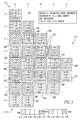
- Figure 3 shows a schematic illustration of a representative first core loading pattern 216 and resulting initial core 214 when employing the advanced method of the present invention in order to emulate the desired equilibrium cycle reload core 114 of Figure 2.
- the reactivity distribution of the desirable equilibrium cycle reload core 114 is known. Such distribution is illustrated in the example of Figure 2.
- much data including data relating to such reactivity distribution, is available with respect to equilibrium cycles for nuclear reactors, generally. Such data has been obtained through years of monitoring the equilibrium cycles of various reactors and through the development and application of many known prior art methods (e.g., algorithms) in the nuclear art over the years in an attempt to optimize in-core fuel management.
- the advanced method of the present invention involves taking such data and applying it to emulate the reactivity distribution of the highly economic and efficient equilibrium cycle reload core 114 (Figure 2), in the initial core 214.
- the method of the present invention emulates a desired end result (e.g., core equilibrium) which typically takes years to achieve, and achieves a comparable result in an initial step (e.g., the initial core 214 of the reactor), thereby dramatically improving fuel management efficiency and economy.
- known parameters of the desired equilibrium cycle reload core 114 such as the initial enrichment of particular fuel assemblies 104, 106, 108 and the burnable absorber loading or amount of burnup of the assembly, and emulating the reactivity distribution which results from such parameters, using only those fuel assembly parameters which may be varied within the initial core 214.
- only initial enrichment, batch quantity and location of the fuel assemblies within the core may be varied because all other parameters are at an initial start up value of zero variability, the initial core has not yet experienced any bumup. Therefore, the method of the present invention backs out an advanced core 214 using known parameters from the desired equilibrium target core and replicating them as closely as possible.
- Figure 3 again illustrates one-eighth of the core 214 and assumes core symmetry. Comparing the initial core 214 of Figure 3 with the equilibrium cycle reload core 114 of Figure 2, it is evident that the exemplary initial core 214 succeeds in closely emulating the spatial reactivity distribution of the very economical target equilibrium cycle reload core 114 both in terms of sub-batch quantity and spatial distribution.
- the method of the present invention unlike the three substantially equal zones of known initial cores (e.g., zones 4, 6 and 8 of Figure 1), provides a core having essentially any necessary, suitable combination and configuration of fuel batches and sub-batches.
- the enrichments of the exemplary initial core 214 are obtained through use of a group of high enrichment bundles 208 of approximately the same size and enrichment as the equilibrium cycle feed batch 108.
- the burned fuel 104, 106 in the equilibrium reload cycle core 114 is approximated through use of initial enrichments that approximate the reactivity of the non-zero beginning of cycle (BOC) bumup and initial enrichment of the burned fuel inventory 104, 106 of the equilibrium reload cycle core 114.
- BOC non-zero beginning of cycle
- the resulting enrichment range of the initial core 214 is much larger than the known prior art (see, e.g., Figure 1).
- the enrichment of the exemplary initial core 214 of Figure 3 ranges from about 0.30 to above about 4.5, as measured in weight of U-235.
- the representative prior art initial core 14 of Figure I has an enrichment range from about 2.35 to about 4.45 weight of U-235.
- the exemplary initial core 214 of Figure 3 includes two high enrichment sub-batches 208, 208' which are sized and enriched to emulate the fresh fuel region or zone 108 of the equilibrium reload cycle 116.
- the next two sub-batches 204, 204' are sized similarly to and are enriched to emulate the reactivity of the once-burned portion 104 of the equilibrium cycle reload core 114.
- the remaining sub-batches, for example, 206, 206' are sized to reflect the twice-burned portion 106 of the reload core 114 with enrichments being similarly selected to emulate the reactivity of the twice-burned fuel 106 in the equilibrium reload core 114.
- the two sub-batches of highly enriched fuel 208, 208' are positioned toward the interior 210 of the core 214 rather than at the periphery 212 like the known prior art (see, e.g., highly enriched fuel 8 at core periphery 12 of Figure 1).
- the method next involves positioning the pair of sub-batches of fuel 206, 206' emulating the twice-burned fuel 106 of the equilibrium cycle reload core 114 primarily at the periphery 212 of the core 214.
- the remainder of the fuel within the initial core 214 can be enriched and arranged as needed, in any combination, in order to replicate the desired equilibrium cycle.
- the initial core 214 shown in Figure 3 includes two sub-batches 204, 204' sized and enriched to emulate the once-burned fuel 104 of the equilibrium core 214.
- Such sub-batches 204, 204' are disposed intermittently, as necessary to achieve the desired reactivity distribution. Accordingly, the initial core 214 and method of implementing the same, of the invention, overcomes the disadvantageous neutron leakage of the prior art, premature removal or replacement of highly enriched fuel and the economic inefficiencies associated therewith.
- the initial core 214 emulates the reactivity distributions of the equilibrium reload core 114, the time or cycle length to transition to the reload core cycle is dramatically improved. Such improvement is due largely to the much wider range of enrichments and to the unequal sub-batch sizes used in the advanced initial core 214.
- This set of advanced core design parameters has the effect of minimizing the discharge enrichment of the initial core 214 and, thereby, maximizing the enrichment of the fuel carried over for further exposure within the reactor.
- the fuel which is carried over from the initial cycle 214 to the reload cycles is of an enrichment and reactivity that is representative of the target reload core 114.
- an advanced lattice design is required.
- the lattice is the array of fuel and the particular arrangement of rod locations in a fuel assembly.
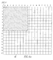
- Figure 4 shows a representative example of such an advanced lattice design 300 for at least some of the fuel assemblies of the exemplary initial core 214.
- Only the upper left quadrant of the lattice 300 is shown.
- Mirror symmetry in the remaining quadrants is assumed (see Figure 4A, highlighting the location of the one-quarter section of Figure 4 within the lattice 300).
- the lattice 300 is designed to compensate for the highly enriched inboard fuel bundles 208, 208' that are adjacent to low enrichment bundles ( e .
- each fuel rod in a given assembly generally has the same enrichment.
- a uniformly enriched bundle design, for the highly enriched bundles, would result in unacceptably high power peaking factors within the exemplary initial core 214 ( Figure 3).
- the advanced lattice design 300 of the present invention uses six different rod types (see, e.g., the key beneath lattice 300 of Figure 4) in a configuration designed to reduce peaking factors when the highly enriched assemblies are adjacent lower enriched assemblies (see, e.g., fuel assemblies 208 adjacent fuel assemblies 206' of Figure 2).
- Lower enriched in this case refers to enrichments ranging from between about 1 to 2.50 weight of U-235, in order to simulate the reactivity of burned assemblies (e.g., 104, 106).
- radial zoning of the bundle 208 is employed to reduce the enrichment of the fuel rods 302 at the edges of the bundle 208 and, thereby, result in a bundle power distribution that compensates for the unusually high thermal neutron flux at the bundle periphery 212 (Figure 3).
- Such enrichment reduction is typically limited to the first two rows 304, 306 of the bundle 208 due to the thermal neutron mean-free path in the high enrichment bundle 208 which is relatively short ( e.g ., roughly one pitch).
- FIG. 4 shows the lattice 300 or how the fuel rods are arranged to form a bundle, such as the high enrichment bundle 208, shown.
- Six types of fuel rods 302, 304, 306, 308, 310, 312 are employed and range, respectively, in level of enrichment from least enriched to most enriched.
- low enrichment in the exemplary case refers to between about 1-2.50 weight of U-235.
- Medium enrichment is preferably between about 2.50-3.50 weight of U-235 and high enrichment is preferably between about 3.50-5 weight of U-235. It will, however, be appreciated that there are variations in enrichment even with these designated categories (e.g., low, medium, high).
- the lattice 300 of Figure 4 has a generally square pattern of adjacent fuel rods.
- the lowest enrichment fuel rods 302 are disposed at the corners of the lattice 300.
- the next lowest enrichment rods 304 are disposed along the sides or edges of the lattice 300.
- the fuel rod enrichments then gradually increase as the rod positions approach the center of the lattice 300 where the most highly enriched fuel rods 310 and next to most highly enriched fuel rods 308 are disposed in a symmetric pattern.
- the foregoing advanced lattice design 300 of the present invention compensates for the thermal flux peak of the environment, primarily caused by the inboard highly enriched bundles 208, 208' (best shown in Figure 3) of the exemplary initial core 214 ( Figure 3) being adjacent low enrichment bundles 206, 206' (best shown in Figure 3), by lowering the enrichment at the edges or sides 304 of the lattice 300, thereby reducing such power peaks and supporting the highly efficient and thus economical initial core 214 ( Figure 3) of the present invention.
Landscapes
- Physics & Mathematics (AREA)
- Engineering & Computer Science (AREA)
- Plasma & Fusion (AREA)
- General Engineering & Computer Science (AREA)
- High Energy & Nuclear Physics (AREA)
- Monitoring And Testing Of Nuclear Reactors (AREA)
Applications Claiming Priority (1)
| Application Number | Priority Date | Filing Date | Title |
|---|---|---|---|
| US96690704A | 2004-10-15 | 2004-10-15 |
Publications (3)
| Publication Number | Publication Date |
|---|---|
| EP1647994A2 true EP1647994A2 (de) | 2006-04-19 |
| EP1647994A3 EP1647994A3 (de) | 2012-02-29 |
| EP1647994B1 EP1647994B1 (de) | 2015-07-15 |
Family
ID=35708433
Family Applications (1)
| Application Number | Title | Priority Date | Filing Date |
|---|---|---|---|
| EP05018755.8A Expired - Lifetime EP1647994B1 (de) | 2004-10-15 | 2005-08-30 | Verfahren zur Durchführung einer Erstspaltzonen-Kernbrennstabbündel-Konfiguration |
Country Status (6)
| Country | Link |
|---|---|
| US (2) | US9293228B2 (de) |
| EP (1) | EP1647994B1 (de) |
| JP (2) | JP2006113072A (de) |
| KR (1) | KR101290842B1 (de) |
| CN (1) | CN1760990B (de) |
| ES (1) | ES2546615T3 (de) |
Cited By (4)
| Publication number | Priority date | Publication date | Assignee | Title |
|---|---|---|---|---|
| CN103151084A (zh) * | 2013-02-21 | 2013-06-12 | 中科华核电技术研究院有限公司 | 一种压水堆堆芯及其新组件换料装载方法 |
| WO2015077404A1 (en) | 2013-11-21 | 2015-05-28 | Terrapower, Llc | Method and system for generating a nuclear reactor core loading distribution |
| CN109741844A (zh) * | 2018-12-29 | 2019-05-10 | 中核北方核燃料元件有限公司 | 一种芯块自动装管装置 |
| CN114242283A (zh) * | 2021-12-22 | 2022-03-25 | 中国核动力研究设计院 | 一种压水堆堆芯24个月换料周期燃料装载方法 |
Families Citing this family (19)
| Publication number | Priority date | Publication date | Assignee | Title |
|---|---|---|---|---|
| CN1760990B (zh) * | 2004-10-15 | 2011-11-30 | 西屋电气有限责任公司 | 改进的首次堆芯燃料组件布置和实现上述布置的方法 |
| CN101206930B (zh) * | 2006-12-22 | 2011-06-15 | 深圳中广核工程设计有限公司 | 多堆联合核燃料循环利用方法 |
| CN101241772B (zh) * | 2007-09-26 | 2011-07-27 | 大亚湾核电运营管理有限责任公司 | 压水堆核电站百万千瓦机组18个月换料方法 |
| CN101847450B (zh) * | 2009-05-27 | 2012-10-03 | 中广核工程有限公司 | 一种核电站燃料联合配置方法 |
| CN102054538B (zh) * | 2009-10-30 | 2013-07-17 | 中国广东核电集团有限公司 | 压水堆核电站百万千瓦机组完全低中子泄漏先进四分之一换料方法及其安全分析系统 |
| CN102184751B (zh) * | 2011-03-01 | 2013-03-20 | 福建福清核电有限公司 | 利用首炉堆芯备用燃料组件提高反应堆燃料安全性的方法 |
| US20140133619A1 (en) * | 2012-04-17 | 2014-05-15 | Babcock & Wilcox Mpower, Inc. | Extended operating cycle for pressurized water reactor |
| CN103871528B (zh) * | 2012-12-14 | 2017-04-05 | 中国核动力研究设计院 | 一种压水堆堆芯的长周期燃料管理方法 |
| CN105843178B (zh) * | 2015-01-13 | 2019-10-01 | 国核(北京)科学技术研究院有限公司 | 用于循环燃料管理的自动换料方法及系统 |
| US10818403B2 (en) * | 2016-03-29 | 2020-10-27 | Nuscale Power, Llc | Inter-module fuel shuffling |
| JP6896561B2 (ja) * | 2016-09-26 | 2021-06-30 | 株式会社東芝 | 軽水炉用燃料集合体、軽水炉炉心、軽水炉用燃料集合体製造方法およびmox燃料集合体製造方法 |
| JP6878251B2 (ja) * | 2017-02-09 | 2021-05-26 | 株式会社東芝 | 軽水炉用燃料集合体、軽水炉炉心設計方法および軽水炉用燃料集合体設計方法 |
| CN108039216B (zh) * | 2017-12-08 | 2019-09-24 | 中国核动力研究设计院 | 一种压水堆堆芯的平衡循环18个月换料装载方法 |
| KR102159723B1 (ko) * | 2018-03-08 | 2020-09-24 | 울산과학기술원 | 가압 경수로 장주기 운전을 위한 핵연료 집합체 및 혼합주기 운전 방법 |
| CN110991809B (zh) * | 2019-11-06 | 2022-11-15 | 中国辐射防护研究院 | 一种基于华龙一号的堆芯积存量实时估算方法 |
| CN111584107B (zh) * | 2020-04-17 | 2022-04-19 | 岭东核电有限公司 | 核电站燃料机组重组替代方法、装置、设备和存储介质 |
| CN115064293B (zh) * | 2022-04-25 | 2025-05-27 | 中国核电工程有限公司 | 一种vver堆型24个月平衡循环的堆芯装载方法 |
| CN117409997B (zh) * | 2023-10-30 | 2026-02-13 | 上海核工程研究设计院股份有限公司 | 长周期高燃耗的燃料管理方法 |
| CN119694617B (zh) * | 2024-12-23 | 2025-11-25 | 中国原子能科学研究院 | 反应堆燃料组件的装载的方法以及铅铋堆的装载的方法 |
Family Cites Families (37)
| Publication number | Priority date | Publication date | Assignee | Title |
|---|---|---|---|---|
| US3432389A (en) * | 1966-07-25 | 1969-03-11 | Combustion Eng | Core design for nuclear reactor |
| JPS5459594A (en) | 1977-10-21 | 1979-05-14 | Hitachi Ltd | Nuclear reactor |
| US4451427A (en) * | 1978-02-03 | 1984-05-29 | Combustion Engineering, Inc. | In-core fuel management for nuclear reactor |
| JPS5572891A (en) * | 1978-11-29 | 1980-06-02 | Hitachi Ltd | Reactor core structure |
| US4574069A (en) | 1980-11-21 | 1986-03-04 | Combustion Engineering, Inc. | In-core fuel management for nuclear reactor |
| JPS57197490A (en) * | 1981-05-29 | 1982-12-03 | Nippon Atomic Ind Group Co | Boiling-water reactor |
| JPS61128185A (ja) | 1984-11-28 | 1986-06-16 | 株式会社日立製作所 | 原子炉炉心 |
| JP2564383B2 (ja) | 1988-12-12 | 1996-12-18 | 株式会社日立製作所 | 原子炉の炉心及び原子炉の燃料装荷方法並びに原子炉の運転方法 |
| US5272736A (en) | 1992-11-05 | 1993-12-21 | General Electric Company | Core loading strategy for reload of a plurality of different fuel bundle fuel designs |
| CA2115876A1 (en) | 1993-03-22 | 1994-09-23 | Henry Alexander Kautz | Methods and apparatus for constraint satisfaction |
| JP3175996B2 (ja) * | 1993-06-04 | 2001-06-11 | 株式会社東芝 | 沸騰水型原子炉の初装荷炉心 |
| US5631939A (en) * | 1994-09-09 | 1997-05-20 | Hitachi, Ltd. | Initial core of nuclear power plant |
| JPH0915361A (ja) | 1995-06-30 | 1997-01-17 | Hitachi Ltd | 初装荷炉心 |
| JP3186546B2 (ja) | 1995-10-11 | 2001-07-11 | 株式会社日立製作所 | 初装荷炉心 |
| US5923717A (en) | 1996-01-29 | 1999-07-13 | General Electric Company | Method and system for determining nuclear core loading arrangements |
| JPH09329682A (ja) * | 1996-06-07 | 1997-12-22 | Hitachi Ltd | 初装荷炉心 |
| WO1998010426A1 (fr) * | 1996-09-04 | 1998-03-12 | Hitachi, Ltd. | Coeur de chargement initial |
| US5822388A (en) | 1996-11-15 | 1998-10-13 | Combustion Engineering Inc. | MOX fuel arrangement for nuclear core |
| US6504889B1 (en) * | 1997-03-17 | 2003-01-07 | Hitachi, Ltd. | Method of operating reactor |
| JP3435308B2 (ja) * | 1997-05-16 | 2003-08-11 | 株式会社日立製作所 | 初装荷炉心 |
| US6934350B1 (en) | 1998-02-17 | 2005-08-23 | General Electric Company | Core configuration for a nuclear reactor |
| FR2778749B1 (fr) | 1998-05-15 | 2000-07-28 | Jay Electronique Sa | Barriere optique formee d'elements emetteurs/recepteurs regroupes en mobiles |
| KR100279614B1 (ko) | 1998-09-10 | 2001-03-02 | 구자홍 | 자기 기록 재생기의 회전 검출장치 및 방법 |
| US6404437B1 (en) | 1999-09-10 | 2002-06-11 | General Electric Company | Nuclear reactor core performance data visualization system |
| DE60007053T2 (de) | 1999-10-14 | 2004-10-21 | Toshiba Kawasaki Kk | Kernbrennstabbündel und Kernreaktor |
| JP4161486B2 (ja) | 1999-10-26 | 2008-10-08 | 株式会社日立製作所 | 沸騰水型原子炉の初装荷炉心 |
| US6748348B1 (en) | 1999-12-30 | 2004-06-08 | General Electric Company | Design method for nuclear reactor fuel management |
| JP2001272489A (ja) * | 2001-03-09 | 2001-10-05 | Hitachi Ltd | 燃料集合体 |
| US6658078B2 (en) | 2001-07-23 | 2003-12-02 | Tokyo Electric Power Co. | MOX nuclear fuel assembly employable for a thermal neutron nuclear reactor |
| US6891912B1 (en) | 2002-06-26 | 2005-05-10 | Pinnacle West Capital Corporation | Fuel assemblies in a reactor core and method of designing and arranging same |
| US7231333B2 (en) | 2003-03-31 | 2007-06-12 | Global Nuclear Fuel - Americas, Llc | Method and arrangement for developing core loading patterns in nuclear reactors |
| US7266481B2 (en) | 2002-12-23 | 2007-09-04 | Global Nuclear Fuel-Americas, Llc | Method, arrangement and computer program for determining standardized rod types for nuclear reactors |
| US7693249B2 (en) | 2003-01-31 | 2010-04-06 | Global Nuclear Fuel - Americas, Llc | Method of improving nuclear reactor performance |
| US6931090B2 (en) * | 2003-02-25 | 2005-08-16 | Westinghouse Electric Company Llc | Method of establishing a nuclear reactor core fuel assembly loading pattern |
| US6862329B1 (en) | 2003-10-06 | 2005-03-01 | Global Nuclear Fuel-Americas Llc | In-cycle shuffle |
| CN1760990B (zh) * | 2004-10-15 | 2011-11-30 | 西屋电气有限责任公司 | 改进的首次堆芯燃料组件布置和实现上述布置的方法 |
| US7224761B2 (en) | 2004-11-19 | 2007-05-29 | Westinghouse Electric Co. Llc | Method and algorithm for searching and optimizing nuclear reactor core loading patterns |
-
2005
- 2005-02-21 CN CN2005100717053A patent/CN1760990B/zh not_active Expired - Lifetime
- 2005-08-22 KR KR1020050076930A patent/KR101290842B1/ko not_active Expired - Lifetime
- 2005-08-30 EP EP05018755.8A patent/EP1647994B1/de not_active Expired - Lifetime
- 2005-08-30 ES ES05018755.8T patent/ES2546615T3/es not_active Expired - Lifetime
- 2005-10-17 JP JP2005301127A patent/JP2006113072A/ja active Pending
-
2012
- 2012-04-19 US US13/451,050 patent/US9293228B2/en active Active
-
2014
- 2014-03-25 JP JP2014061594A patent/JP6010573B2/ja not_active Expired - Lifetime
-
2015
- 2015-12-02 US US14/956,469 patent/US9984779B2/en not_active Expired - Lifetime
Cited By (9)
| Publication number | Priority date | Publication date | Assignee | Title |
|---|---|---|---|---|
| CN103151084A (zh) * | 2013-02-21 | 2013-06-12 | 中科华核电技术研究院有限公司 | 一种压水堆堆芯及其新组件换料装载方法 |
| CN103151084B (zh) * | 2013-02-21 | 2016-02-03 | 中科华核电技术研究院有限公司 | 一种压水堆堆芯及其新组件换料装载方法 |
| WO2015077404A1 (en) | 2013-11-21 | 2015-05-28 | Terrapower, Llc | Method and system for generating a nuclear reactor core loading distribution |
| US10566100B2 (en) | 2013-11-21 | 2020-02-18 | Terrapower, Llc | Method and system for generating a nuclear reactor core loading distribution |
| US10593436B2 (en) | 2013-11-21 | 2020-03-17 | Terrapower, Llc | Method and system for generating a nuclear reactor core loading distribution |
| EP3074982B1 (de) * | 2013-11-21 | 2023-06-07 | TerraPower LLC | Verfahren und system zur erzeugung einer kernladungsverteilung eines kernreaktors |
| CN109741844A (zh) * | 2018-12-29 | 2019-05-10 | 中核北方核燃料元件有限公司 | 一种芯块自动装管装置 |
| CN109741844B (zh) * | 2018-12-29 | 2022-10-21 | 中核北方核燃料元件有限公司 | 一种芯块自动装管装置 |
| CN114242283A (zh) * | 2021-12-22 | 2022-03-25 | 中国核动力研究设计院 | 一种压水堆堆芯24个月换料周期燃料装载方法 |
Also Published As
| Publication number | Publication date |
|---|---|
| JP6010573B2 (ja) | 2016-10-19 |
| US9293228B2 (en) | 2016-03-22 |
| CN1760990A (zh) | 2006-04-19 |
| EP1647994A3 (de) | 2012-02-29 |
| KR20060050547A (ko) | 2006-05-19 |
| EP1647994B1 (de) | 2015-07-15 |
| KR101290842B1 (ko) | 2013-07-29 |
| JP2014142356A (ja) | 2014-08-07 |
| JP2006113072A (ja) | 2006-04-27 |
| ES2546615T3 (es) | 2015-09-25 |
| US20160111174A1 (en) | 2016-04-21 |
| CN1760990B (zh) | 2011-11-30 |
| US9984779B2 (en) | 2018-05-29 |
| US20120294406A1 (en) | 2012-11-22 |
Similar Documents
| Publication | Publication Date | Title |
|---|---|---|
| US9984779B2 (en) | Advanced first core fuel assembly configuration | |
| US4285769A (en) | Control cell nuclear reactor core | |
| US5677938A (en) | Method for fueling and operating a nuclear reactor core | |
| US6263038B1 (en) | MOX fuel arrangement for nuclear core | |
| US4451427A (en) | In-core fuel management for nuclear reactor | |
| US5781604A (en) | Initial core and fuel assembly | |
| EP1658620B1 (de) | Verfahren zum betrieb eines kernreaktors | |
| US4574069A (en) | In-core fuel management for nuclear reactor | |
| EP3062312A1 (de) | Kern eines kernreaktors | |
| JPH05249270A (ja) | 原子炉の炉心 | |
| CA1107409A (en) | In-core fuel management for nuclear reactor | |
| US5319685A (en) | Method for operation of a boiling water nuclear reactor | |
| JPH1090461A (ja) | 原子炉初装荷炉心及び燃料装荷方法 | |
| JPS6166988A (ja) | 燃料の装荷方法 | |
| Urban et al. | Advanced fuel assemblies for economic and flexible operation of light water reactors | |
| JPH058398B2 (de) | ||
| JPH10319162A (ja) | 初装荷炉心 | |
| MXPA97006919A (en) | Method for fuel supply and operating the central laparte of a nucl reactor | |
| JPH1123762A (ja) | 燃料集合体及び初装荷炉心 | |
| JP2001099972A (ja) | 沸騰水型原子炉の初装荷炉心及びその燃料交換方法 | |
| JPH04249794A (ja) | 原子炉初装荷炉心の運転方法 | |
| JPH03251794A (ja) | 原子炉の初装荷炉心 | |
| JPH0422894A (ja) | 沸騰水型原子炉の運転方法 | |
| JPH0472595A (ja) | 原子炉の炉心及び燃料の装荷方法 | |
| JPH09243773A (ja) | 沸騰水型原子炉の炉心 |
Legal Events
| Date | Code | Title | Description |
|---|---|---|---|
| PUAI | Public reference made under article 153(3) epc to a published international application that has entered the european phase |
Free format text: ORIGINAL CODE: 0009012 |
|
| AK | Designated contracting states |
Kind code of ref document: A2 Designated state(s): AT BE BG CH CY CZ DE DK EE ES FI FR GB GR HU IE IS IT LI LT LU LV MC NL PL PT RO SE SI SK TR |
|
| AX | Request for extension of the european patent |
Extension state: AL BA HR MK YU |
|
| PUAL | Search report despatched |
Free format text: ORIGINAL CODE: 0009013 |
|
| AK | Designated contracting states |
Kind code of ref document: A3 Designated state(s): AT BE BG CH CY CZ DE DK EE ES FI FR GB GR HU IE IS IT LI LT LU LV MC NL PL PT RO SE SI SK TR |
|
| AX | Request for extension of the european patent |
Extension state: AL BA HR MK YU |
|
| RIC1 | Information provided on ipc code assigned before grant |
Ipc: G21C 19/20 20060101ALI20120125BHEP Ipc: G21C 3/326 20060101ALI20120125BHEP Ipc: G21C 5/00 20060101AFI20120125BHEP |
|
| 17P | Request for examination filed |
Effective date: 20120829 |
|
| 17Q | First examination report despatched |
Effective date: 20120927 |
|
| AKX | Designation fees paid |
Designated state(s): ES FR GB SE |
|
| REG | Reference to a national code |
Ref country code: DE Ref legal event code: R108 |
|
| REG | Reference to a national code |
Ref country code: DE Ref legal event code: R108 Effective date: 20121107 |
|
| GRAP | Despatch of communication of intention to grant a patent |
Free format text: ORIGINAL CODE: EPIDOSNIGR1 |
|
| GRAS | Grant fee paid |
Free format text: ORIGINAL CODE: EPIDOSNIGR3 |
|
| INTG | Intention to grant announced |
Effective date: 20150512 |
|
| GRAA | (expected) grant |
Free format text: ORIGINAL CODE: 0009210 |
|
| AK | Designated contracting states |
Kind code of ref document: B1 Designated state(s): ES FR GB SE |
|
| REG | Reference to a national code |
Ref country code: GB Ref legal event code: FG4D |
|
| REG | Reference to a national code |
Ref country code: FR Ref legal event code: PLFP Year of fee payment: 11 |
|
| REG | Reference to a national code |
Ref country code: ES Ref legal event code: FG2A Ref document number: 2546615 Country of ref document: ES Kind code of ref document: T3 Effective date: 20150925 |
|
| REG | Reference to a national code |
Ref country code: SE Ref legal event code: TRGR |
|
| PLBE | No opposition filed within time limit |
Free format text: ORIGINAL CODE: 0009261 |
|
| STAA | Information on the status of an ep patent application or granted ep patent |
Free format text: STATUS: NO OPPOSITION FILED WITHIN TIME LIMIT |
|
| 26N | No opposition filed |
Effective date: 20160418 |
|
| REG | Reference to a national code |
Ref country code: FR Ref legal event code: PLFP Year of fee payment: 12 |
|
| REG | Reference to a national code |
Ref country code: FR Ref legal event code: PLFP Year of fee payment: 13 |
|
| REG | Reference to a national code |
Ref country code: FR Ref legal event code: PLFP Year of fee payment: 14 |
|
| PGFP | Annual fee paid to national office [announced via postgrant information from national office to epo] |
Ref country code: GB Payment date: 20200826 Year of fee payment: 16 Ref country code: FR Payment date: 20200828 Year of fee payment: 16 Ref country code: ES Payment date: 20200901 Year of fee payment: 16 |
|
| PGFP | Annual fee paid to national office [announced via postgrant information from national office to epo] |
Ref country code: SE Payment date: 20200826 Year of fee payment: 16 |
|
| REG | Reference to a national code |
Ref country code: SE Ref legal event code: EUG |
|
| GBPC | Gb: european patent ceased through non-payment of renewal fee |
Effective date: 20210830 |
|
| PG25 | Lapsed in a contracting state [announced via postgrant information from national office to epo] |
Ref country code: SE Free format text: LAPSE BECAUSE OF NON-PAYMENT OF DUE FEES Effective date: 20210831 |
|
| PG25 | Lapsed in a contracting state [announced via postgrant information from national office to epo] |
Ref country code: GB Free format text: LAPSE BECAUSE OF NON-PAYMENT OF DUE FEES Effective date: 20210830 Ref country code: FR Free format text: LAPSE BECAUSE OF NON-PAYMENT OF DUE FEES Effective date: 20210831 |
|
| REG | Reference to a national code |
Ref country code: ES Ref legal event code: FD2A Effective date: 20220930 |
|
| PG25 | Lapsed in a contracting state [announced via postgrant information from national office to epo] |
Ref country code: ES Free format text: LAPSE BECAUSE OF NON-PAYMENT OF DUE FEES Effective date: 20210831 |