EP1647836A2 - Radar antenna for monitoring the environment of a motor vehicle - Google Patents
Radar antenna for monitoring the environment of a motor vehicle Download PDFInfo
- Publication number
- EP1647836A2 EP1647836A2 EP05028254A EP05028254A EP1647836A2 EP 1647836 A2 EP1647836 A2 EP 1647836A2 EP 05028254 A EP05028254 A EP 05028254A EP 05028254 A EP05028254 A EP 05028254A EP 1647836 A2 EP1647836 A2 EP 1647836A2
- Authority
- EP
- European Patent Office
- Prior art keywords
- antenna
- delay lines
- radar antenna
- radar
- terminals
- Prior art date
- Legal status (The legal status is an assumption and is not a legal conclusion. Google has not performed a legal analysis and makes no representation as to the accuracy of the status listed.)
- Withdrawn
Links
Images


Classifications
-
- H—ELECTRICITY
- H01—ELECTRIC ELEMENTS
- H01Q—ANTENNAS, i.e. RADIO AERIALS
- H01Q21/00—Antenna arrays or systems
- H01Q21/06—Arrays of individually energised antenna units similarly polarised and spaced apart
- H01Q21/061—Two dimensional planar arrays
- H01Q21/065—Patch antenna array
-
- G—PHYSICS
- G01—MEASURING; TESTING
- G01S—RADIO DIRECTION-FINDING; RADIO NAVIGATION; DETERMINING DISTANCE OR VELOCITY BY USE OF RADIO WAVES; LOCATING OR PRESENCE-DETECTING BY USE OF THE REFLECTION OR RERADIATION OF RADIO WAVES; ANALOGOUS ARRANGEMENTS USING OTHER WAVES
- G01S7/00—Details of systems according to groups G01S13/00, G01S15/00, G01S17/00
- G01S7/02—Details of systems according to groups G01S13/00, G01S15/00, G01S17/00 of systems according to group G01S13/00
- G01S7/03—Details of HF subsystems specially adapted therefor, e.g. common to transmitter and receiver
- G01S7/032—Constructional details for solid-state radar subsystems
-
- H—ELECTRICITY
- H01—ELECTRIC ELEMENTS
- H01Q—ANTENNAS, i.e. RADIO AERIALS
- H01Q1/00—Details of, or arrangements associated with, antennas
- H01Q1/27—Adaptation for use in or on movable bodies
- H01Q1/32—Adaptation for use in or on road or rail vehicles
- H01Q1/3208—Adaptation for use in or on road or rail vehicles characterised by the application wherein the antenna is used
- H01Q1/3233—Adaptation for use in or on road or rail vehicles characterised by the application wherein the antenna is used particular used as part of a sensor or in a security system, e.g. for automotive radar, navigation systems
-
- H—ELECTRICITY
- H01—ELECTRIC ELEMENTS
- H01Q—ANTENNAS, i.e. RADIO AERIALS
- H01Q1/00—Details of, or arrangements associated with, antennas
- H01Q1/27—Adaptation for use in or on movable bodies
- H01Q1/32—Adaptation for use in or on road or rail vehicles
- H01Q1/325—Adaptation for use in or on road or rail vehicles characterised by the location of the antenna on the vehicle
- H01Q1/3283—Adaptation for use in or on road or rail vehicles characterised by the location of the antenna on the vehicle side-mounted antennas, e.g. bumper-mounted, door-mounted
-
- H—ELECTRICITY
- H01—ELECTRIC ELEMENTS
- H01Q—ANTENNAS, i.e. RADIO AERIALS
- H01Q23/00—Antennas with active circuits or circuit elements integrated within them or attached to them
-
- H—ELECTRICITY
- H01—ELECTRIC ELEMENTS
- H01Q—ANTENNAS, i.e. RADIO AERIALS
- H01Q25/00—Antennas or antenna systems providing at least two radiating patterns
- H01Q25/002—Antennas or antenna systems providing at least two radiating patterns providing at least two patterns of different beamwidth; Variable beamwidth antennas
-
- H—ELECTRICITY
- H01—ELECTRIC ELEMENTS
- H01Q—ANTENNAS, i.e. RADIO AERIALS
- H01Q25/00—Antennas or antenna systems providing at least two radiating patterns
- H01Q25/007—Antennas or antenna systems providing at least two radiating patterns using two or more primary active elements in the focal region of a focusing device
- H01Q25/008—Antennas or antenna systems providing at least two radiating patterns using two or more primary active elements in the focal region of a focusing device lens fed multibeam arrays
-
- G—PHYSICS
- G01—MEASURING; TESTING
- G01S—RADIO DIRECTION-FINDING; RADIO NAVIGATION; DETERMINING DISTANCE OR VELOCITY BY USE OF RADIO WAVES; LOCATING OR PRESENCE-DETECTING BY USE OF THE REFLECTION OR RERADIATION OF RADIO WAVES; ANALOGOUS ARRANGEMENTS USING OTHER WAVES
- G01S13/00—Systems using the reflection or reradiation of radio waves, e.g. radar systems; Analogous systems using reflection or reradiation of waves whose nature or wavelength is irrelevant or unspecified
- G01S13/88—Radar or analogous systems specially adapted for specific applications
- G01S13/93—Radar or analogous systems specially adapted for specific applications for anti-collision purposes
- G01S13/931—Radar or analogous systems specially adapted for specific applications for anti-collision purposes of land vehicles
- G01S2013/9325—Radar or analogous systems specially adapted for specific applications for anti-collision purposes of land vehicles for inter-vehicle distance regulation, e.g. navigating in platoons
-
- G—PHYSICS
- G01—MEASURING; TESTING
- G01S—RADIO DIRECTION-FINDING; RADIO NAVIGATION; DETERMINING DISTANCE OR VELOCITY BY USE OF RADIO WAVES; LOCATING OR PRESENCE-DETECTING BY USE OF THE REFLECTION OR RERADIATION OF RADIO WAVES; ANALOGOUS ARRANGEMENTS USING OTHER WAVES
- G01S13/00—Systems using the reflection or reradiation of radio waves, e.g. radar systems; Analogous systems using reflection or reradiation of waves whose nature or wavelength is irrelevant or unspecified
- G01S13/88—Radar or analogous systems specially adapted for specific applications
- G01S13/93—Radar or analogous systems specially adapted for specific applications for anti-collision purposes
- G01S13/931—Radar or analogous systems specially adapted for specific applications for anti-collision purposes of land vehicles
- G01S2013/9327—Sensor installation details
- G01S2013/93271—Sensor installation details in the front of the vehicles
-
- G—PHYSICS
- G01—MEASURING; TESTING
- G01S—RADIO DIRECTION-FINDING; RADIO NAVIGATION; DETERMINING DISTANCE OR VELOCITY BY USE OF RADIO WAVES; LOCATING OR PRESENCE-DETECTING BY USE OF THE REFLECTION OR RERADIATION OF RADIO WAVES; ANALOGOUS ARRANGEMENTS USING OTHER WAVES
- G01S13/00—Systems using the reflection or reradiation of radio waves, e.g. radar systems; Analogous systems using reflection or reradiation of waves whose nature or wavelength is irrelevant or unspecified
- G01S13/88—Radar or analogous systems specially adapted for specific applications
- G01S13/93—Radar or analogous systems specially adapted for specific applications for anti-collision purposes
- G01S13/931—Radar or analogous systems specially adapted for specific applications for anti-collision purposes of land vehicles
- G01S2013/9327—Sensor installation details
- G01S2013/93275—Sensor installation details in the bumper area
-
- H—ELECTRICITY
- H01—ELECTRIC ELEMENTS
- H01L—SEMICONDUCTOR DEVICES NOT COVERED BY CLASS H10
- H01L2924/00—Indexing scheme for arrangements or methods for connecting or disconnecting semiconductor or solid-state bodies as covered by H01L24/00
- H01L2924/0001—Technical content checked by a classifier
- H01L2924/0002—Not covered by any one of groups H01L24/00, H01L24/00 and H01L2224/00
Definitions
- the present invention relates to a radar antenna, which is particularly suitable for monitoring the environment of a motor vehicle, according to the preamble of claim 1.
- Such radar antennas are needed for different comfort and safety-relevant driver assistance systems. They use forward-facing sensors in the direction of travel to gather information about traffic and obstacles on the road. This information is used by the associated driver assistance system to perform automatic ranging or automatic emergency braking, or to use for adaptive cruise control, collision avoidance, and future autonomous vehicle driving applications.
- a radar sensor which has a control circuit and a radar antenna, wherein the control circuit is designed as a transmitting and receiving module and wherein the radar antenna is connected to at least one supply line to the control circuit.
- a part of the control circuit is designed as an MMIC (monolithic millimeter-wave integrated circuit).
- the radar antenna is in the form of a printed circuit and has a red lens and a group antenna.
- the red-lens lens has a lenticular parallel plate line, at least two lead terminals, a plurality of docking terminals, and delay lines. Furthermore, the array antenna is composed of a plurality of individual antennas, which are connected in series to at least two rows. Each of these series of individual antennas is connected to a delay line which transmits the high-frequency signal delivered by the parallel plate line to the associated coupling terminal to the row of individual antennas.
- a further disadvantage of the radar antenna known from the prior art is that in the transmission of the high-frequency signals between the array antenna and the Rotmanlinse a defined phase relationship between the respective rows of individual antennas and the associated coupling terminals of the red lens is given.
- a variable amplitude distribution of the high frequency signals to the separate rows of individual antennas of the array antenna in this radar antenna is not possible.
- the directional characteristic of the array antenna can not be set optimally.
- the invention is therefore based on the technical problem of designing and developing the radar antenna known from the prior art in such a way that the disadvantages of the prior art described above are eliminated.
- a radar sensor with a control circuit which is designed as a transmitting and / or receiving module and has at least one MMIC (monolithic millimeter-wave integrated circuit), and with a radar antenna over at least one supply line is connected to the control circuit and has a red lens and a group antenna, wherein the control circuit and the radar antenna are arranged substantially parallel to each other.
- MMIC monolithic millimeter-wave integrated circuit
- a line carrier is provided, wherein lines for transmitting high-frequency signals between the control circuit and the at least one supply line of the radar antenna are arranged on the line carrier, wherein the line carrier is arranged between the control circuit and the radar antenna.
- the signal transmission between the differently dimensioned components namely the at least one MMIC component and the radar antenna
- the additional conductor carrier lines can be made prior to assembly of the radar sensor and thus the actual connections between the at least one MMIC component and the radar antenna can be made in a simple manner after assembly including the cable carrier.
- the lines arranged on the conductor carrier are dimensioned at their connection points to the at least one MMIC component and to the radar antenna in a suitable manner.
- the lines run on the conductor carrier substantially in a plane parallel to the conductor tracks of the control circuit and the at least one supply line of the radar antenna.
- these lines are arranged substantially at the same height as the control circuit and the radar antenna, the result is an arrangement of the different line elements, which lie substantially in one plane.
- the lines are formed as microstrip lines on the line carrier, which are particularly suitable for the transmission of high-frequency electromagnetic signals.
- a circuit carrier is provided, with which the at least one MMIC component of the control circuit, the line carrier and at least partially the radar antenna, preferably with an adhesive, are connected.
- the circuit carrier can therefore also be referred to as a multi-chip module.
- all components form a unit, which are interconnected via circuit carriers.
- transmission lines for signal transmission between the lines of the line carrier and the feed connections of the radar antenna can also be formed on the circuit carrier.
- the circuit carrier also partially takes on functional tasks.
- connection possibilities between the lines of the conductor carrier and the at least one supply line of the radar antenna on the one hand wire bonds and on the other hand electromagnetic field couplings are possible.
- the very exact cutting of the connecting elements must be taken into account, since the electrical properties of the wire bond significantly depend on this accuracy.
- a connection by electromagnetic field coupling allows higher manufacturing tolerances of the individual elements, but requires a greater amount of circuit design.
- An important advantage of the structure described above is the modularity. Because it can be used with different radar antennas different control circuits in the form of prefabricated MMIC components for different applications. The assembly and connection takes place on the circuit board.
- a radar antenna having a red lens having a parallelepiped-shaped lenticular line, at least two lead terminals, a plurality of coupling terminals and delay lines, and a group antenna having a plurality of individual antennas.
- Delay line is provided which transmits the output from the parallel plate line to the associated coupling port high-frequency signal to the series of individual antennas, and wherein for a given frequency of the high-frequency signal, the lengths of the delay lines are chosen so that upon application of the high-frequency signal to each of the supply terminals Signals with a predetermined phase distribution at the antenna terminals, wherein the signal propagation times that occur between the supply terminals and the antenna terminals are varied for different predetermined frequency lines of the high-frequency signal by substantially integral multiple of the periods of the signal to an amplitude distribution of the specify the signals applied to the antenna terminals.
- the signal propagation times for external delay lines be extended in relation to internal delay lines.
- the advantage of this embodiment is that compared to the radar antenna known from the prior art, not only is a suitable phase allocation on the rows of individual antennas of the array antenna achieved, but beyond that now is possible, the amplitude distribution of the voltage applied to the rows of individual antennas Targeting signals.
- different geometric lengths of the delay lines predetermine the signal propagation times along the delay lines.
- the high-frequency signals are fed with a predetermined by the injected signal phase relationship to the various rows of individual antennas. This is possible because of the narrow band of the high-frequency signal to be transmitted, since the frequency differences within the bandwidth of the high-frequency signal only lead to negligible phase differences due to different signal propagation times. As a result, a very accurate directional characteristic of the array antenna is achieved.
- a radar antenna having a red lens which includes a lenticular parallel-parallel line, at least two lead terminals, a plurality of Coupling terminals and delay lines, and with a group antenna having a plurality of individual antennas, which are connected to at least two rows each in series, wherein the rotor lens and the array antenna are arranged substantially parallel and spaced from each other.
- a space-saving arrangement of red lens and array antenna is achieved in an advantageous manner, so that a planar design of the radar antenna and beyond the radar sensor is possible, which greatly simplifies a deployment in a motor vehicle.
- it is, for example, possible to integrate a planar radar sensor, or a planar radar antenna in the bumper of a motor vehicle. This includes the arrangement of the red lens and the array antenna on a substrate side by side with a.
- the red lens and the array antenna are formed on two different substrates, wherein the two substrates are connected to each other with their side facing away from the red lens or the array antenna and wherein between the two substrates a common metallization layer is arranged.
- This preferably serves as a common ground for the red lens and the array antenna.
- coupling slots are formed in the metallization layer, which couple the antenna terminals of the rows of individual antennas of the array antenna with the connection points of the delay lines electromagnetically.
- connection points of the rows of individual antennas are arranged substantially in the middle of the rows, whereby a symmetrical amplitude distribution is achieved on the individual antennas within a row of individual antennas.
- the directional characteristic of the radar antenna is further improved.
- a motor vehicle 1 which has at its front end in the region of the bumper a radar sensor 2 with a radar antenna 4 which has an azimuthal directional characteristic which has a separate sensitivity for different angular sections ⁇ .
- objects can be detected with angular resolution to characterize the environment of the motor vehicle 1.
- the determination of the distance R and the relative velocity v is also possible, so that vehicles or objects traveling in front can be detected on the road, in order thus to influence the driving behavior of the motor vehicle 1.
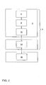
- Fig. 2 shows a block diagram of the general structure of the entire radar sensor and a downstream evaluation system.
- the radar antenna 4 In the front end 6, the radar antenna 4, a control circuit 8 and an analog / digital converter 10 are arranged.
- the control circuit 8 is designed as a transmitting and / or receiving module and has at least one MMIC device.
- the radar antenna 4 is connected to at least one feed line 12 to the control circuit 8.
- the analog / digital converter 10 is connected to a trained as an electronic control unit first controller 14, which in turn is connected to a second control device, which is formed, for example, as a vehicle-internal evaluation computer.
- a second control device which is formed, for example, as a vehicle-internal evaluation computer.
- the electronic control unit of the first control unit 14 is not only used to evaluate the signals received by the radar antenna 4, but also the control of the radar antenna 4 for emitting radar signals. Therefore, in the embodiment shown in Fig. 2, the radar antenna 4 is formed monostatically, so serves both as a transmitting antenna and as a receiving antenna.
- a bistatic embodiment of the radar sensor with two different radar antennas 4 is possible, one of which serves as a transmitting antenna and the other as a receiving antenna.
- These can be dimensioned differently and adapted in each case to the requirements as a transmitting or receiving antenna.
- a small transmitting antenna is sufficient for completely illuminating the area to be monitored, while the receiving antenna has a larger antenna area due to the necessary angular resolution.
- a central unit of the radar sensor 2 according to the invention is the control circuit 8, which is designed as a transmitting and receiving module. On the one hand, it has the task of providing the frequency-modulated radar signal with sufficient power of the radar antenna 4. On the other hand, the control circuit 8 mixes the signal received by the radar antenna 4 with a local oscillator signal, so that a signal is produced in the baseband.
- the control circuit 8 as a transmitting and receiving module thus represents the interface between the signal processing and the radar antenna 4 and the radar antennas 4.
- both the radar antenna 4 and the control circuit 8 are constructed in planar technology. As already mentioned, the control circuit 8 has MMIC components for this purpose.
- FIG. 3 schematically shows a first example of a radar sensor.
- the control circuit 8 has two MMIC components 18 and 20, which realize, inter alia, the functions of the ozillator and an I / O mixer.
- the radar sensor has a planar radar antenna 4, which-as will be explained in more detail below-has a red-lens lens 22 and an array antenna 24, which are applied to a substrate 26.
- a line carrier 28 is provided, are formed on the lines 30, which serve for the transmission of high-frequency signals between the MMIC components 18 and 20 of the control circuit 8 and the leads 12 of the radar antenna 4.
- the line carrier 28 between the control circuit 8, so the MMIC components 18 and 20, and the radar antenna 4 is arranged.
- the lines 30 formed on the line carrier 28 extend substantially in a plane parallel to the tracks of the control circuit 8 and the leads 12 of the radar antenna 4. This advantageously achieves that the connections between the lines 30 and the leads 12 of the radar antenna 4 and the MMIC components 18 and 20 can be made very short. As a result, in particular the losses in the transmission of high-frequency signals are kept to a minimum.
- the lines 30 for the transmission of high-frequency signals are formed as microstrip lines on the line carrier 28.
- the line carrier 28 is, for example, made of GaAs or Al 2 O 3 .
- microstrip lines based on GaAs is carried out in a plurality of manufacturing steps.
- a wafer is divided into samples which have meaningful sizes for the production of the conductor carriers. This is done by scribing a predetermined breaking point with a diamond and breaking the wafer over an edge. Subsequently, the wafer piece is thinned to a required thickness by a wet chemical etching polishing method. In addition to the etching attack of the etching solution, such as bromomethane solution, the reduction in thickness is also supported by a purely mechanical abrasion on a polishing cloth. Thereafter, the wafer pieces are cleaned to ensure good adhesion of the metallization on the GaAs. For this purpose, both the self-oxide and organic contaminants are removed from the semiconductor surface.
- the metallization occurs to prevent re-formation of native oxide on the sample surface.
- the metallization consists of a 10nm thick primer made of chrome, a 100nm thick vapor deposited gold layer and finally 3 ⁇ m electroplated gold. Since a microstrip line has its ground potential on the substrate lower side, both sides of the wafer piece serving as a substrate must be metallized.
- the sample consisting of the substrate and metallization is glued to a glass slide with a photoresist. On the one hand, this step facilitates the handling of the sensitive GaAs and, on the other hand, the metallization on the back of the sample is protected during the etching.
- the photoresist is dissolved in acetone and the sample is thus released from its support again.
- they are subjected to a paint ashing step, so that in particular remain on the tracks no paint residues, which lead to a deteriorated adhesion of a bonding wire.
- the samples are cut with high precision into the GaAs conductor carriers.
- a circuit carrier 32 which provides a stable basis for the assembly of the sensitive MMIC devices 18 and 20 and for the line carrier 28. These are connected to the circuit substrate 32 with an adhesive.
- the radar antenna 4 is partially also connected to the circuit carrier 32.
- the material of the circuit substrate 32 is adapted to the thermal expansion behavior of the substrates of the MMIC components 18 and 20, the conductor support 28 and the radar antenna 4, which occur in particular when used with a motor vehicle large temperature differences ,
- Al 2 O 3 has been selected in the present exemplary embodiment.
- 32 lines for power supply and for connection to the first control unit 14 are formed directly on the substrate of the circuit substrate.
- the circuit carrier 32 also has a further function.
- the MMIC components 18 and 20, the line carrier 28 and in part the radar antenna 4 are connected to the circuit carrier 32.
- the line carrier 28 is not connected by means of a wire bond 31, but with the aid of an electromagnetic field coupling 34, as will be explained in more detail with reference to FIG.
- the substrate 36 on which the radar antenna 4 is at least partly formed, namely in the form of the red-lens 22, has on the side shown in FIG. 5 at the top a mass metallization which has a recess 40 and therein a coplanar line 42.
- a ground metallization 44, a recess 46 and a coplanar line 48 are formed symmetrically to the configuration of the surface of the substrate 36.
- the circuit substrate 32 is reversed with the surface shown in Fig. 5 upside down on the substrate 36 for abutment, whereby the two Koplanar effeten 42 and 48 at least partially overlapping each other.
- the Coplanar lines 42 are also shown in Fig. 7 in their arrangement relative to the leads 12.
- a supply line 12 is shown in Fig. 5 with dashed lines, which is designed as a microstrip line.
- the arrow 52 points in the direction of the radar antenna 4, in particular the red-lens 22.
- the line carrier 28 which has a line 30 in the form of a microstrip line with the surface 30 facing away from the surface mounted on the circuit substrate 32, as shown by the arrow 54.
- the arrow 56 points in the direction of the control circuit 8, with which the line 30 is connected.
- Both the feed line 12 and the line 30 are not electrically conductively connected to the coplanar lines 42 and 48, respectively, but they are each spaced from the coplanar lines 42 and 48 by the substrates 36 and 32, respectively.
- the lead 30 is electromagnetically coupled to the lead 12 via a series connection of two microstrip coplanar junctions.
- the first junction connects the line carrier 28 to the circuit carrier 32 and the second transition ensures the coupling of the Rotman lens 22 with the circuit substrate 32.
- the connection of the two Koplanartechnischen 42 and 48 is carried out galvanically by a flip-chip assembly.
- the above-described modular design of the radar sensor is simplified by the flip-chip mounting, since without major adaptation problems different MMIC components of various control circuits can be connected to the circuit substrate 32 and the radar antenna 4.
- the construction described above saves space.
- FIG. 6 shows an exemplary embodiment of a radar antenna 4 according to the invention, which can be used in the exemplary embodiments of the radar sensor 2 described above.
- the radar antenna 4 has a red lens 22 having a lenticular parallel plate line 56, five lead terminals 58a to 58e, a plurality of docking terminals 60, and delay lines 62.
- the radar antenna 4 has a group antenna 24 which has a plurality of individual antennas 64 which are connected in series to a plurality of rows 66. For each row 66 of individual antennas 64 is a delay line 62 is provided which transmits the output from the parallel plate line 56 to the respective associated coupling port 60 high-frequency signal to the row 66 of individual antennas.
- All other connections 68 serve the electrical termination of the parallel plate line 56 and are covered with an absorber material, for example, in the form of a film (not shown).
- all connections that is to say the supply connections 58a to 58e, the connection connections 60 and the termination connections 68 are transferred to microstrip lines in an impendance-matched manner using tap stone tapers.
- the supply connections 58a to 58e shown on the left in FIG. 6 are fed to the electronic control circuit 8 and the coupling connections 60 on the right to the group antenna 24.
- the shape of the parallel plate line 56 and the delay lines 62 is formed so that a targeted phase assignment to the antenna terminals 63 shown in Fig. 6 is realized at a suitable excitation in the focal plane, which is in Fig. 6 in the region of the lead terminals 58a to 58e ,
- a suitable excitation in the focal plane which is in Fig. 6 in the region of the lead terminals 58a to 58e .
- the high-frequency signal is supplied to one of the two outer supply terminals 58a or 58e, then a signal is applied to the coupling terminals 63 which predetermines a fixed phase relationship but has a phase shift between the individual coupling terminals 60.
- the parallel plate line 56 and the delay lines 62 are formed so that the phase relation linearly extends from the upper to the lower coupling terminals 63 shown in FIG.
- the parallel plate line 56 is designed so that an exactly linear phase characteristic is achieved for three focal points of the lens.
- the two outer lead terminals 58a and 58e and the middle lead terminal 58c are the three foci of the red lens.
- the signal propagation times that occur between the lead terminals (58) and the antenna terminals (63) are varied by substantially integer multiples of the periods of the signal for different predetermined delay lines (62) for a given frequency of the high frequency signal to provide an amplitude distribution of the signals at the Antenna connections (63) specify signals.
- the signal propagation times for external delay lines (62) are extended with respect to internal delay lines (62).
- the high-frequency signals applied to the coupling terminals 63 are supplied with their predetermined phase relationship to the rows 66 of the individual antennas 64. If, for example, the middle supply line connection 58c is subjected to the high-frequency signal, high-frequency signals are produced at the coupling connections 63 whose phase shift is substantially equal to zero.
- the outer delay lines 62 have a greater length than the middle delay lines 62, the high-frequency signals are more attenuated on the outside, so that an amplitude distribution is formed within the array antenna 24 having higher in the middle and lower in amplitude. As a result, the directivity of the array antenna 24 can be advantageously influenced.
- the different signal propagation times along the delay lines 62 are predetermined by different geometric lengths. This can be clearly recognized by the more or less curved contours of the delay lines 62. It is also possible to adjust the signal propagation times by different dielectric constants of the substrates used for the delay lines 62, since the electromagnetic signals propagate along the delay lines and are influenced by the dielectric constant of the substrate in its transit time.
- the directional characteristic of the antenna in each case has a main lobe, while in both azimuthal directions side lobes occur whose intensity is considerably lower than that of the main lobe.
- the azimuthal orientation of the main lobe can be controlled by a different control of the Rotman lens on the different supply lines 58a to 58e. Because depending on the phase relationship between the various individual antennas 64, the direction of the main lobe is shifted. Thereby An angular resolution of the radar antenna 4 is achieved without mechanical adjustment solely by electronic means.
- the directional characteristic of the array antenna 24 is also influenced by the fact that the arranged in Fig. 6 above and below rows 66 of the individual antennas 64 are subjected to a signal whose amplitude is lower than that for the rows 66 shown in the middle in Fig. 6 the case is, as already explained above. Thereby, the generation of electromagnetic radiation in the center of the planar array antenna 24 is concentrated.
- a drive with different amplitude is achieved in that the delay lines for the outer rows 66 are significantly longer than for the middle rows 66, whereby the high-frequency signal is attenuated until it enters the outer rows 66 stronger than it is for the middle Delay lines 62 is the case. Due to damping effects alone, a suitable amplitude distribution of the high-frequency signals within the array antenna 24 is thus achieved.
- the delay lines 62 are connected to one of the two ends of the rows 66 of individual antennas 64, respectively.
- the red-lens 22 and the array antenna 24 are formed on a substrate, which substantially corresponds to the embodiment shown in Fig. 3.
- the red lens 22 and the array antenna 24 are arranged substantially in a plane, whereby a planar design of the entire radar antenna is achieved.
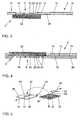
- FIG. 7 shows an additional example of a radar antenna 4 in an exploded view.
- the red lens 22 has the previously described parallel plate line 56, lead terminals 58, docking terminals 60, and delay lines 62.
- the array antenna 24 has individual antennas 64 connected in series 70 in series.
- the rows 70 of individual antennas differ from those of the first embodiment in that, as will be described in detail below, the coupling of the electromagnetic signals takes place substantially in the middle of the rows 70.
- Rotmanlinse 22 and the array antenna 24 parallel and spaced from each other. In contrast to the formation in a plane in the first embodiment, therefore, Rotman lens 22 and array antenna 24 are at least partially arranged overlapping one another.
- the red-lens lens 22 is on a first substrate 72 and the array antenna on a second substrate 74 educated.
- the two substrates 72 and 74, with their sides facing away from the red-lens lens 22 or the array antenna 24, are connected to one another by means of a common metallization layer 76.
- the metallization layer 76 serves as common ground potential.
- the above-described two-layer structure of the radar antenna 4 is also shown in Fig. 4 and in Fig. 8.
- coupling slots 78 are formed in the metallization layer 76, which couple the connection points 80 of the rows 70 of the individual antennas 64 electromagnetically with the connection points 82 of the delay lines 62.
- the electromagnetic field is transmitted from the pads 82 through the substrate 22, through the coupling slots 78, and through the substrate 74 to the pads 80 of the array antenna 24.
- the metallization layer 76 is formed substantially over the entire surface, a good shielding of the red lens 22 is achieved by the array antenna 24 in an advantageous manner.
- a coupling slot 78 and two connection points 80 and 82 is also shown in Fig. 8. Since the coupling slot 78 specifies only a limited spatial area for the electromagnetic coupling of the two connection points 80 and 82, on the one hand a precise defined excitation of the rows 70 takes place and on the other hand a good shielding in the areas outside the coupling slots 78 is ensured.
- the control of the array antenna 24 has been described as a transmitting antenna, wherein the electromagnetic signals from the red lens 22 on the array antenna 24 is carried out.
- the array antenna 24 As a receiving antenna, the signal propagation takes place in the opposite way.
- FIGS. 9 to 11 show a more detailed embodiment of the individual antennas as well as the rows 70 and 66 of individual antennas 64 in detail.
- Fig. 9 shows a single antenna 64 with a feed line 84, which is designed as a microstrip line, and with a radiation surface 86, which is also called patch.
- the length the radiation surface 86 is predetermined by the frequency of the high-frequency signal and corresponds essentially to half the wavelength of the radiation in the substrate.
- the width (b) and the relative position of the feed point (x) are selectable within limits, with both parameters being matched to one another in order to ensure good input matching.
- the edge of the radiation surface 86 labeled y is also referred to as the nonradiative side, and the two edges labeled b are referred to as the radiating sides of the radiation surface 86.
- the two parameters width (b) and length (y) can be varied within limits, as a result of which the size of the power coupled out of the row 70 or 66 for the respective individual antenna 64 and, moreover, the amplitude distribution within the row 70 or 66 can be set.
- a feed network in the form of a three-port series circuit is constructed, as shown in FIG.
- a three-port is composed of two ⁇ / 4 transformers and a single antenna branch. Assuming that all individual antennas 64 work in phase, the decoupling points must therefore be electrically 360 ° apart. The connecting piece between two three-tone converters must therefore realize an electrical phase rotation of 180 °.
- the single three gates are further designed such that along the row 70, a defined fraction of the power P is a coupled in the feed strand into the supply line of the single antenna 64 depending on the desired amplitude of occupancy of the individual antennas 64th
- Z 2 is the impedance level of the feed line 84 of the single antenna 64, while Z 0 is to be referred to as the feed line impedance level.
- these can also be arranged or strung in series within the strand. The amplitude of the respective decoupled signals is then controlled across the width of the radiation surfaces.
- connection points 80 are arranged substantially in the middle of the rows 70, wherein, as shown in FIG. 11, a subdivision into ⁇ / 2 and ⁇ is made to have an equal phase with electromagnetic waves propagating along the rows 70 in two different directions to ensure the left and right of the connection point 80 individual antennas 64.
- the substrates of the red-lens 22 and the array antenna 24 are made of a ceramic-filled composite of polytetrafluoroethylene (PTFE).
- PTFE polytetrafluoroethylene
- the size of the red lens 22 can be reduced with use of a high dielectric constant regardless of the dimensions given by the outer shape of the array antenna 24.
Abstract
Description
Die vorliegende Erfindung betrifft eine Radarantenne, die insbesondere für ein Überwachen der Umgebung eines Kraftfahrzeuges geeignet ist, nach dem Oberbegriff des Anspruchs 1.The present invention relates to a radar antenna, which is particularly suitable for monitoring the environment of a motor vehicle, according to the preamble of
Derartige Radarantennen werden für unterschiedliche Komfort- und sicherheitsrelevante Fahrerassistenz-Systeme benötigt. Sie verwenden in Fahrtrichtung nach vorne ausgerichtete Sensoren, um Informationen über den Verkehr und Hindernisse auf der Straße zu sammeln. Diese Informationen werden von dem zugeordneten Fahrerassistenz-System verwendet, um eine automatische Distanzregelung oder eine automatische Notbremsfunktion durchzuführen oder für Anwendungen aus dem Bereich der adaptiven Fahrtregelung, der Kollisionsverhinderung und für das zukünftige autonome Fahren von Fahrzeugen zu verwenden.Such radar antennas are needed for different comfort and safety-relevant driver assistance systems. They use forward-facing sensors in the direction of travel to gather information about traffic and obstacles on the road. This information is used by the associated driver assistance system to perform automatic ranging or automatic emergency braking, or to use for adaptive cruise control, collision avoidance, and future autonomous vehicle driving applications.
Aus der IEEE Transactions on Mircowave Theory and Techniques, VOL. 45, NO. 12 Dezember 1997, "Milimeter-Wave Radar Sensor for Automotive Intelligent Cruise Control (ICC)", M. E. Russell et al. ist ein Radarsensor bekannt, der eine Steuerschaltung und eine Radarantenne aufweist, wobei die Steuerschaltung als Sende- und Empfangsmodul ausgebildet ist und wobei die Radarantenne mit mindestens einer Zuleitung mit der Steuerschaltung verbunden ist. Ein Teil der Steuerschaltung ist dabei als MMIC (monolithic millimeterwave integrated circuit) ausgebildet. Darüber hinaus ist die Radarantenne in Form eines gedruckten Schaltkreises ausgebildet und weist eine Rotmanlinse und eine Gruppenantenne auf. Die Rotmanlinse weist eine linsenförmige Parallelplattenleitung, mindestens zwei Zuleitungsanschlüsse, eine Mehrzahl von Ankopplungsanschlüssen und Verzögerungsleitungen auf. Weiterhin ist die Gruppenantenne aus einer Mehrzahl von Einzelantennen aufgebaut, die zu mindestens zwei Reihen in Serie geschaltet sind. Jede dieser Reihe von Einzelantennen ist mit einer Verzögerungsleitung verbunden, die das von der Parallelplattenleitung an den zugeordneten Ankopplungsanschluß abgegebene hochfrequente Signal auf die Reihe von Einzelantennen überträgt.From the IEEE Transactions on Mircowave Theory and Techniques, Vol. 45, NO. 12 December 1997, "Milimeter-Wave Radar Sensor for Automotive Intelligent Cruise Control (ICC)", ME Russell et al. a radar sensor is known which has a control circuit and a radar antenna, wherein the control circuit is designed as a transmitting and receiving module and wherein the radar antenna is connected to at least one supply line to the control circuit. A part of the control circuit is designed as an MMIC (monolithic millimeter-wave integrated circuit). In addition, the radar antenna is in the form of a printed circuit and has a red lens and a group antenna. The red-lens lens has a lenticular parallel plate line, at least two lead terminals, a plurality of docking terminals, and delay lines. Furthermore, the array antenna is composed of a plurality of individual antennas, which are connected in series to at least two rows. Each of these series of individual antennas is connected to a delay line which transmits the high-frequency signal delivered by the parallel plate line to the associated coupling terminal to the row of individual antennas.
Bei dem zuvor dargestellten Radarsensor besteht das Problem in der Verbindung bzw. Ankopplung der MMIC-Bausteine an die Radarantenne, da unterschiedlich dimensionierte und auf verschiedenen Substraten angeordnete Schaltkreise miteinander verbunden werden müssen. Dabei treten häufig Verluste auf, da die Verbindungsleitungen nicht optimal an die Übertragung von hochfrequenten Signalen angepaßt sind.In the radar sensor described above, there is the problem in the connection or coupling of the MMIC components to the radar antenna, since different sized and arranged on different substrates circuits must be connected to each other. In this case, losses often occur because the connection lines are not optimally adapted to the transmission of high-frequency signals.
Ein weiterer Nachteil bei der aus dem Stand der Technik bekannten Radarantenne besteht darin, daß bei der Übertragung der hochfrequenten Signale zwischen der Gruppenantenne und der Rotmanlinse zwar eine definierte Phasenbeziehung zwischen den jeweiligen Reihen der Einzelantennen und den zugeordneten Ankopplungsanschlüssen der Rotmanlinse gegeben ist. Jedoch ist eine variable Amplitudenverteilung der Hochfrequenzsignale auf die separaten Reihen von Einzelantennen der Gruppenantenne bei dieser Radarantenne nicht möglich. Dadurch kann die Richtungscharakteristik der Gruppenantenne nicht optimal eingestellt werden.A further disadvantage of the radar antenna known from the prior art is that in the transmission of the high-frequency signals between the array antenna and the Rotmanlinse a defined phase relationship between the respective rows of individual antennas and the associated coupling terminals of the red lens is given. However, a variable amplitude distribution of the high frequency signals to the separate rows of individual antennas of the array antenna in this radar antenna is not possible. As a result, the directional characteristic of the array antenna can not be set optimally.
Weiterhin besteht bei der oben beschriebenen, aus dem Stand der Technik bekannten Radarantenne ein Problem darin, daß der gesamte Radarsensor aufgrund der Anordnung der Rotmanlinse und der Gruppenantenne im rechten Winkel zueinander ein großes Volumen des Radarsensors einnimmt. Somit können nur ungenügend die Anforderungen an die Abmessungen eines Radarsensors erfüllt werden, um ihn bspw. im Bereich der Stoßstange eines Kraftfahrzeuges anzuordnen.Furthermore, in the above-described radar antenna known from the prior art, there is a problem in that the entire radar sensor occupies a large volume of the radar sensor due to the arrangement of the red lens and the array antenna at right angles to each other. Thus, the requirements for the dimensions of a radar sensor can be met only insufficient to order it, for example, in the bumper of a motor vehicle.
Der Erfindung liegt daher das technische Problem zugrunde, die aus dem Stand der Technik bekannte Radarantenne derart auszugestalten und weiterzubilden, daß die zuvor beschriebenen Nachteile des Standes der Technik behoben werden.The invention is therefore based on the technical problem of designing and developing the radar antenna known from the prior art in such a way that the disadvantages of the prior art described above are eliminated.
Nach einer ersten Lehre der vorliegenden Erfindung wird das zuvor genannte technische Problem gelöst durch einen Radarsensor mit einer Steuerschaltung, die als Sende- und/oder Empfangsmodul ausgebildet ist und mindestens einen MMIC (monolithic millimeterwave integrated circuit) aufweist, und mit einer Radarantenne, die über mindestens eine Zuleitung mit der Steuerschaltung verbunden ist und eine Rotmanlinse und eine Gruppenantenne aufweist, wobei die Steuerschaltung und die Radarantenne im wesentlichen parallel zueinander angeordnet sind.According to a first teaching of the present invention, the aforementioned technical problem is solved by a radar sensor with a control circuit which is designed as a transmitting and / or receiving module and has at least one MMIC (monolithic millimeter-wave integrated circuit), and with a radar antenna over at least one supply line is connected to the control circuit and has a red lens and a group antenna, wherein the control circuit and the radar antenna are arranged substantially parallel to each other.
Aufgrund der planaren Ausgestaltung des gesamten Radarsensors ergibt sich ein kompakter, ein geringes Volumen einnehmender Aufbau, so daß der erfindungsgemäße Radarsensor sich ohne Probleme in den Bereich der Stoßstange eines Kraftfahrzeuges integrieren läßt.Due to the planar design of the entire radar sensor results in a compact, a low volume occupying structure, so that the radar sensor according to the invention can be integrated without problems in the bumper of a motor vehicle.
Bei einer bevorzugten Ausgestaltung ist ein Leitungsträger vorgesehen, wobei Leitungen zur Übertragung von Hochfrequenzsignalen zwischen der Steuerschaltung und der mindestens einen Zuleitung der Radarantenne auf dem Leitungsträger angeordnet sind, wobei der Leitungsträger zwischen der Steuerschaltung und der Radarantenne angeordnet ist.In a preferred embodiment, a line carrier is provided, wherein lines for transmitting high-frequency signals between the control circuit and the at least one supply line of the radar antenna are arranged on the line carrier, wherein the line carrier is arranged between the control circuit and the radar antenna.
Durch den zuvor genannten Aufbau des Radarsensors kann die Signalübertragung zwischen den unterschiedlich dimensionierten Bausteinen, nämlich dem mindestens einem MMIC-Bauelement und der Radarantenne durch einen weiteren Baustein wirkungsvoll realisiert werden. Dazu können die auf dem zusätzlichen Leitungsträger angeordneten Leitungen vor einer Montage des Radarsensors hergestellt werden und somit können die eigentlichen Verbindungen zwischen dem mindestens einen MMIC-Bauelement und der Radarantenne in einfacher Weise nach der Montage einschließlich des Leitungsträgers hergestellt werden. Dabei ist gewährleistet, daß die auf dem Leitungsträger angeordneten Leitungen an ihren Anschlußstellen zu dem mindestens einen MMIC-Bauelement und zu der Radarantenne in geeigneter Weise dimensioniert sind.By means of the aforementioned structure of the radar sensor, the signal transmission between the differently dimensioned components, namely the at least one MMIC component and the radar antenna, can be effectively realized by a further component. For this purpose, arranged on the additional conductor carrier lines can be made prior to assembly of the radar sensor and thus the actual connections between the at least one MMIC component and the radar antenna can be made in a simple manner after assembly including the cable carrier. In this case, it is ensured that the lines arranged on the conductor carrier are dimensioned at their connection points to the at least one MMIC component and to the radar antenna in a suitable manner.
Dabei ist bevorzugt, daß die Leitungen auf dem Leitungsträger im wesentlichen in einer Ebene parallel zu den Leiterbahnen der Steuerschaltung und der mindestens eine Zuleitung der Radarantenne verlaufen. Sind zusätzlich diese Leitungen im wesentlichen auf einer gleichen Höhe wie die Steuerschaltung und die Radarantenne angeordnet, so ergibt sich eine Anordnung der verschiedenen Leitungselemente, die im wesentlichen in einer Ebene liegen. Die somit realisierten elektrischen bzw. elektromagnetischen Verbindungen zwischen den verschiedenen Bausteinen werden somit auf ein Minimum reduziert, so daß auftretende Verluste minimiert werden.It is preferred that the lines run on the conductor carrier substantially in a plane parallel to the conductor tracks of the control circuit and the at least one supply line of the radar antenna. In addition, if these lines are arranged substantially at the same height as the control circuit and the radar antenna, the result is an arrangement of the different line elements, which lie substantially in one plane. The thus realized electrical or electromagnetic connections between the various components are thus reduced to a minimum, so that occurring losses are minimized.
In weiter bevorzugter Weise sind die Leitungen als Mikrostreifenleitungen auf den Leitungsträger ausgebildet, die insbesondere für die Übertragung von hochfrequenten elektromagnetischen Signalen geeignet sind.In a further preferred manner, the lines are formed as microstrip lines on the line carrier, which are particularly suitable for the transmission of high-frequency electromagnetic signals.
Bei einer weiteren Ausgestaltung der Erfindung ist ein Schaltungsträger vorgesehen, mit dem das mindestens eine MMIC-Bauelement der Steuerschaltung, der Leitungsträger und zumindest teilweise die Radarantenne, vorzugsweise mit einem Klebstoff, verbunden sind. Der Schaltungsträger kann daher auch als Multichipmodul bezeichnet werden. Somit bilden sämtliche Bauelemente eine Einheit, die über Schaltungsträger miteinander verbunden sind. Auf dem Schaltungsträger können zusätzlich auch Übertragungsleitungen zur Signalübertragung zwischen den Leitungen des Leitungsträgers und den Zuleitungsanschlüssen der Radarantenne ausgebildet sein. Somit übernimmt der Schaltungsträger auch teilweise funktionale Aufgaben.In a further embodiment of the invention, a circuit carrier is provided, with which the at least one MMIC component of the control circuit, the line carrier and at least partially the radar antenna, preferably with an adhesive, are connected. The circuit carrier can therefore also be referred to as a multi-chip module. Thus, all components form a unit, which are interconnected via circuit carriers. In addition, transmission lines for signal transmission between the lines of the line carrier and the feed connections of the radar antenna can also be formed on the circuit carrier. Thus, the circuit carrier also partially takes on functional tasks.
Als Verbindungsmöglichkeiten zwischen den Leitungen des Leitungsträgers und der mindestens einen Zuleitung der Radarantenne sind einerseits Drahtbondverbindungen und andererseits elektromagnetische Feldkopplungen möglich. Bei der Drahtbondverbindung ist dabei der sehr genaue Zuschnitt der Verbindungselemente zu beachten, da die elektrischen Eigenschaften der Drahtbondverbindung maßgeblich von dieser Genauigkeit abhängen. Daneben erlaubt eine Verbindung durch elektromagnetische Feldkopplung höhere Fertigungstorleranzen der einzelnen Elemente, erfordert jedoch einen höheren Aufwand an Schaltungsdesign.As connection possibilities between the lines of the conductor carrier and the at least one supply line of the radar antenna on the one hand wire bonds and on the other hand electromagnetic field couplings are possible. In the case of the wire bond connection, the very exact cutting of the connecting elements must be taken into account, since the electrical properties of the wire bond significantly depend on this accuracy. In addition, a connection by electromagnetic field coupling allows higher manufacturing tolerances of the individual elements, but requires a greater amount of circuit design.
Ein wichtiger Vorteil des zuvor beschriebenen Aufbaus besteht in der Modularität. Denn es können mit gleichen Radarantennen unterschiedliche Steuerschaltungen in Form vorgefertigter MMIC-Bauelemente für unterschiedliche Anwendungszwecke verwendet werden. Die Montage und Verbindung erfolgt auf dem Schaltungsträger.An important advantage of the structure described above is the modularity. Because it can be used with different radar antennas different control circuits in the form of prefabricated MMIC components for different applications. The assembly and connection takes place on the circuit board.
Weiterhin wird darauf hingewiesen, daß die Ausgestaltung der zuvor beschriebenen Erfindung unabhängig von der speziellen Form der Radarantenne ist. Bevorzugt ist jedoch die nachfolgende erfindungsgemäße Ausgestaltung der Radarantenne.Furthermore, it should be noted that the embodiment of the invention described above is independent of the specific shape of the radar antenna. However, the following embodiment of the radar antenna according to the invention is preferred.
Gemäß einer zweiten Lehre der vorliegenden Erfindung wird das oben genannte technische Problem gelöst durch eine Radarantenne mit einer Rotmanlinse, die eine linsenförmige Parallelplattenleitung, mindestens zwei Zuleitungsanschlüsse, eine Mehrzahl von Ankopplungsanschlüssen und Verzögerungsleitungen aufweist, und mit einer Gruppenantenne, die eine Mehrzahl von Einzelantennen aufweist, die zu mindestens zwei Reihen jeweils in Serie geschaltet sind, wobei jede Reihe mit einem Antennenanschluss mit einer Verzögerungsleitung verbunden ist, wobei für jede Reihe von Einzelantennen eine Verzögerungsleitung vorgesehen ist, die das von der Parallelplattenleitung an den zugeordneten Ankopplungsanschluss abgegebene hochfrequente Signal auf die Reihe von Einzelantennen überträgt, und wobei für eine vorgegebene Frequenz des hochfrequenten Signals die Längen der Verzögerungsleitungen so gewählt sind, dass bei Anlegen des hochfrequenten Signals an jeden der Zuleitungsanschlüsse Signale mit einer vorgegebenen Phasenverteilung an den Antennenanschlüssen anliegen, wobei die Signallaufzeiten, die zwischen den Zuleitungsanschlüssen und den Antennenanschlüssen auftreten, für verschiedene Verzögerungsleitungen für eine vorgegebene Frequenz des hochfrequenten Signals um im wesentlichen ganzzahlige Vielfach der Perioden des Signals verändert sind, um eine Amplitudenverteilung der an den Antennenanschlüssen anliegenden Signale vorzugeben.According to a second teaching of the present invention, the above technical problem is solved by a radar antenna having a red lens having a parallelepiped-shaped lenticular line, at least two lead terminals, a plurality of coupling terminals and delay lines, and a group antenna having a plurality of individual antennas. each connected in series with at least two rows, each row having an antenna terminal connected to a delay line, one for each row of individual antennas Delay line is provided which transmits the output from the parallel plate line to the associated coupling port high-frequency signal to the series of individual antennas, and wherein for a given frequency of the high-frequency signal, the lengths of the delay lines are chosen so that upon application of the high-frequency signal to each of the supply terminals Signals with a predetermined phase distribution at the antenna terminals, wherein the signal propagation times that occur between the supply terminals and the antenna terminals are varied for different predetermined frequency lines of the high-frequency signal by substantially integral multiple of the periods of the signal to an amplitude distribution of the specify the signals applied to the antenna terminals.
Dabei ist es bevorzugt, dass die Signallaufzeiten für außen liegende Verzögerungsleitungen gegenüber innen liegenden Verzögerungsleitungen verlängert sind. Der Vorteil dieser Ausgestaltung liegt darin, dass gegenüber der aus dem bisherigen Stand der Technik bekannten Radarantenne nicht nur eine geeignete Phasenbelegung an den Reihen von Einzelantennen der Gruppenantenne erreicht wird, sondern dass darüber hinaus nunmehr möglich ist, die Amplitudenverteilung der an den Reihen der Einzelantennen anliegenden Signale gezielt einzustellen.In this case, it is preferred that the signal propagation times for external delay lines be extended in relation to internal delay lines. The advantage of this embodiment is that compared to the radar antenna known from the prior art, not only is a suitable phase allocation on the rows of individual antennas of the array antenna achieved, but beyond that now is possible, the amplitude distribution of the voltage applied to the rows of individual antennas Targeting signals.
In bevorzugter Weise geben dabei unterschiedliche geometrische Längen der Verzögerungsleitungen die Signallaufzeiten entlang der Verzögerungsleitungen vor. Andererseits ist es möglich, durch unterschiedliche Dielektrizitätskonstanten der für die Verzögerungsleitungen verwendeten Substrate die Signallaufzeiten entlang der Verzögerungsleitungen vorzugeben. Vorteilhaft ist in jedem Fall, daß die hochfrequenten Signale mit einer durch das eingespeiste Signal vorgegebenen Phasenbeziehung den verschiedenen Reihen von Einzelantennen zugeleitet werden. Dieses ist aufgrund der Schmalbandigkeit des zu übertragenden Hochfrequenzsignals möglich, da die Frequenzunterschiede innerhalb der Bandbreite des Hochfrequenzsignals nur zu vernachlässigbaren Phasendifferenzen aufgrund verschiedener Signallaufzeiten führen. Dadurch wird eine sehr genaue Richtcharakteristik der Gruppenantenne erreicht.In a preferred manner, different geometric lengths of the delay lines predetermine the signal propagation times along the delay lines. On the other hand, it is possible to specify the signal propagation times along the delay lines by means of different dielectric constants of the substrates used for the delay lines. It is advantageous in any case that the high-frequency signals are fed with a predetermined by the injected signal phase relationship to the various rows of individual antennas. This is possible because of the narrow band of the high-frequency signal to be transmitted, since the frequency differences within the bandwidth of the high-frequency signal only lead to negligible phase differences due to different signal propagation times. As a result, a very accurate directional characteristic of the array antenna is achieved.
Gemäß einer dritten Lehre der vorliegenden Erfindung wird das oben genannte technische Problem gelöst durch eine Radarantenne mit einer Rotmanlinse, die eine linsenförmige Parallelplalttenleitung, mindestens zwei Zuleitungsanschlüsse, eine Mehrzahl von Ankopplungsanschlüssen und Verzögerungsleitungen aufweist, und mit einer Gruppenantenne, die eine Mehrzahl von Einzelantennen aufweist, die zu mindestens zwei Reihen jeweils in Serie geschaltet sind, wobei die Rotmanlinse und die Gruppenantenne im wesentlichen parallel und beabstandet zueinander angeordnet sind.According to a third teaching of the present invention, the above-mentioned technical problem is solved by a radar antenna having a red lens which includes a lenticular parallel-parallel line, at least two lead terminals, a plurality of Coupling terminals and delay lines, and with a group antenna having a plurality of individual antennas, which are connected to at least two rows each in series, wherein the rotor lens and the array antenna are arranged substantially parallel and spaced from each other.
Bei dieser Anordnung wird in vorteilhafter Weise eine platzsparende Anordnung von Rotmanlinse und Gruppenantenne erreicht, so daß eine planare Ausführung der Radarantenne und darüber hinaus des Radarsensors möglich wird, die einen Einsatz in einem Kraftfahrzeug erheblich vereinfacht. Somit ist es bspw. möglich, einen flächigen Radarsensor, bzw. eine flächige Radarantenne in die Stoßstange eines Kraftfahrzeuges zu integrieren. Dieser schließt die Anordnung der Rotmanlinse und der Gruppenantenne auf einen Substrat nebeneinander mit ein.In this arrangement, a space-saving arrangement of red lens and array antenna is achieved in an advantageous manner, so that a planar design of the radar antenna and beyond the radar sensor is possible, which greatly simplifies a deployment in a motor vehicle. Thus, it is, for example, possible to integrate a planar radar sensor, or a planar radar antenna in the bumper of a motor vehicle. This includes the arrangement of the red lens and the array antenna on a substrate side by side with a.
Bei einer bevorzugten Ausgestaltung sind die Rotmanlinse und die Gruppenantenne auf zwei verschiedenen Substraten ausgebildet, wobei die beiden Substrate mit ihren der Rotmanlinse bzw. der Gruppenantenne abgewandten Seite miteinander verbunden sind und wobei zwischen den beiden Substraten eine gemeinsame Metallisierungsschicht angeordnet ist. Diese dient bevorzugt als gemeinsame Masse für die Rotmanlinse und die Gruppenantenne.In a preferred embodiment, the red lens and the array antenna are formed on two different substrates, wherein the two substrates are connected to each other with their side facing away from the red lens or the array antenna and wherein between the two substrates a common metallization layer is arranged. This preferably serves as a common ground for the red lens and the array antenna.
In weiter bevorzugter Weise sind in der Metallisierungsschicht Koppelschlitze ausgebildet, die die Antennenanschlüsse der Reihen von Einzelantennen der Gruppenantenne mit den Anschlußpunkten der Verzögerungsleitungen elektromagnetisch koppeln. Damit sind zwei wesentliche Vorteile verbunden. Zum einen braucht keine metallische Verbindung zwischen den Verzögerungsleitungen und den Reihen von Einzelantennen hergestellt werden. Zum anderen wird die Gruppenantenne durch das von der Rotmanlinse erzeugte elektromagnetische Feld nur an den dafür vorgesehenen Koppelschlitzen beeinflußt, im übrigen dient die Metallisierungsschicht einer Abschirmung zwischen der Rotmanlinse und der Gruppenantenne.In a further preferred manner, coupling slots are formed in the metallization layer, which couple the antenna terminals of the rows of individual antennas of the array antenna with the connection points of the delay lines electromagnetically. There are two main advantages associated with this. Firstly, no metallic connection between the delay lines and the rows of individual antennas needs to be made. On the other hand, the group antenna is influenced by the electromagnetic field generated by the red lens only at the designated coupling slots, otherwise the metallization serves a shield between the red lens and the array antenna.
Weiterhin bevorzugt sind die Anschlußpunkte der Reihen von Einzelantennen im wesentlichen in der Mitte der Reihen angeordnet, wodurch eine symmetrische Amplitudenverteilung auf die Einzelantennen innerhalb einer Reihe von Einzelantennen erreicht wird. Dadurch wird die Richtcharakteristik der Radarantenne weiter verbessert.Further preferably, the connection points of the rows of individual antennas are arranged substantially in the middle of the rows, whereby a symmetrical amplitude distribution is achieved on the individual antennas within a row of individual antennas. As a result, the directional characteristic of the radar antenna is further improved.
Weitere Merkmale und Vorteile der vorliegenden Erfindung sind in der nachfolgenden Beschreibung von Ausführungsbeispielen näher erläutert. Dabei wird auf die beigefügte Zeichnung bezug genommen. In dieser zeigen
- Fig. 1
- ein Kraftfahrzeug mit einem erfindungsgemäßen Radarsensor, die Abstrahlcharakteristik darstellend,
- Fig. 2
- ein Blockschaltbild des erfindungsgemäßen Radarsensors,
- Fig. 3
- ein erstes Ausführungsbeispiel eines erfindungsgemäßen Radarsensors im Querschnitt,
- Fig. 4
- ein zweites Ausführungsbeispiel eines erfindungsgemäßen Radarsensors im Querschnitt,
- Fig. 5
- eine Explosionsdarstellung zur Darstellung der Montage eines Schaltungsträgers,
- Fig. 6
- ein erstes Ausführungsbeispiel einer erfindungsgemäßen Radarantenne in einer Draufsicht,
- Fig. 7
- eine Explosionsdarstellung einer weiteren Radarantenne,
- Fig. 8
- eine Teilansicht der in Fig. 7 dargestellten Radarantenne im Querschnitt,
- Fig. 9
- eine Einzelantenne in einer Draufsicht,
- Fig. 10
- einen Ausschnitt aus einer Reihe von Einzelantennen in einer Draufsicht und
- Fig. 11
- zwei Reihen von Einzelantennen die Position der Koppelschlitze darstellend.
- Fig. 1
- a motor vehicle with a radar sensor according to the invention, representing the emission characteristic,
- Fig. 2
- a block diagram of the radar sensor according to the invention,
- Fig. 3
- A first embodiment of a radar sensor according to the invention in cross section,
- Fig. 4
- A second embodiment of a radar sensor according to the invention in cross section,
- Fig. 5
- an exploded view illustrating the mounting of a circuit substrate,
- Fig. 6
- A first embodiment of a radar antenna according to the invention in a plan view,
- Fig. 7
- an exploded view of another radar antenna,
- Fig. 8
- a partial view of the radar antenna shown in Fig. 7 in cross section,
- Fig. 9
- a single antenna in a plan view,
- Fig. 10
- a section of a series of individual antennas in a plan view and
- Fig. 11
- two rows of individual antennas representing the position of the coupling slots.
Fig. 1 zeigt ein Kraftfahrzeug 1, das an seinem vorderen Ende im Bereich der Stoßstange einen Radarsensor 2 mit einer Radarantenne 4 aufweist, die eine azimutale Richtcharakteristik aufweist, die für verschiedene Winkelabschnitte ϕ eine separate Empfindlichkeit aufweist. Somit können Objekte winkelaufgelöst erfaßt werden, um die Umgebung des Kraftfahrzeuges 1 zu charakterisieren. Neben dem Winkel ϕ ist zudem die Bestimmung des Abstandes R und der relativen Geschwindigkeit v möglich, so daß vorausfahrende Fahrzeuge oder Gegenstände auf der Fahrbahn erkannt werden können, um somit das Fahrverhalten des Kraftfahrzeuges 1 zu beeinflussen.1 shows a
Fig. 2 zeigt mit einem Blockschaltbild den generellen Aufbau des gesamten Radarsensors sowie eines nachgeschalteten Auswertesystems. Im Frontend 6 sind die Radarantenne 4, eine Steuerschaltung 8 und ein Analog/Digital-Wandler 10 angeordnet. Die Steuerschaltung 8 ist dabei als Sende- und/oder Empfangsmodul ausgebildet und weist mindestens ein MMIC-Bauelement auf. Die Radarantenne 4 ist mit mindestens einer Zuleitung 12 mit der Steuerschaltung 8 verbunden.Fig. 2 shows a block diagram of the general structure of the entire radar sensor and a downstream evaluation system. In the
Der Analog/Digital-Wandler 10 ist mit einem als elektronische Steuerungseinheit ausgebildenten ersten Steuergerät 14 verbunden, das wiederum mit einem zweiten Steuergerät verbunden ist, das bspw. als fahrzeuginterner Auswerterechner ausgebildet ist. In diesem findet die Auswertung der von der Radarantenne 4 empfangenen Signale statt, um in geeigneter Weise auf das Fahrverhalten des Kraftfahrzeuges 1 einzuwirken. Die elektronische Steuerungseinheit des ersten Steuergerätes 14 dagegen dient nicht nur zur Auswertung der von der Radarantenne 4 empfangenen Signale, sondern auch der Ansteuerung der Radarantenne 4 zum Aussenden von Radarsignalen. Daher ist bei dem in Fig. 2 dargestellten Ausführungsbeispiel die Radarantenne 4 monostatisch ausgebildet, dient also sowohl als Sendeantenne als auch als Empfangsantenne. Dagegen ist selbstverständlich auch eine bistatische Ausgestaltung des Radarsensors mit zwei verschiedenen Radarantennen 4 möglich, von denen eine als Sendeantenne und die andere als Empfangsantenne dient. Diese können unterschiedlich dimensioniert sein und jeweils an die Anforderungen als Sende- oder Empfangsantenne angepaßt sein. So reicht bspw. eine kleine Sendeantenne zum vollständigen Ausleuchten des zu überwachenden Bereiches aus, während die Empfangsantenne aufgrund der notwendigen Winkelauflösung eine größere Antennenfläche aufweist.The analog /
Eine zentrale Einheit des erfindungsgemäßen Radarsensors 2 ist die Steuerschaltung 8, die als Sende- und Empfangsmodul ausgebildet ist. Sie hat zum einen die Aufgabe, das frequenzmodulierte Radarsignal mit ausreichender Leistung der Radarantenne 4 zur Verfügung zu stellen. Zum anderen mischt die Steuerschaltung 8 das von der Radarantenne 4 empfangene Signal mit einem Lokaloszillatorsignal, so daß ein Signal im Basisband entsteht. Die Steuerschaltung 8 als Sende- und Empfangsmodul stellt somit die Schnittstelle zwischen der Signalverarbeitung und der Radarantenne 4 bzw. den Radarantennen 4 dar. Bei der erfindungsgemäßen Ausgestaltung des Radarsensors 2 sind sowohl die Radarantenne 4 als auch die Steuerschaltung 8 in planarer Technik aufgebaut. Wie bereits erwähnt, weist dazu die Steuerschaltung 8 MMIC-Bauelemente auf.A central unit of the
In Fig. 3 ist schematisch ein erstes Beispiel eines Radarsensors dargestellt. Die Steuerschaltung 8 weist zwei MMIC-Bauelemente 18 und 20 auf, die unter anderem die Funktionen des Ozillators und eines I/O-Mischers realisieren. Weiterhin weist der Radarsensor eine planare Radarantenne 4 auf, die - wie unten näher erläutert wird - eine Rotmanlinse 22 und eine Gruppenantenne 24 aufweist, die auf einem Substrat 26 aufgebracht sind.FIG. 3 schematically shows a first example of a radar sensor. The
Weiterhin ist ein Leitungsträger 28 vorgesehen, auf dem Leitungen 30 ausgebildet sind, die zur Übertragung von Hochfrequenzsignalen zwischen den MMIC-Bauelementen 18 und 20 der Steuerschaltung 8 und den Zuleitungen 12 der Radarantenne 4 dienen. Dazu ist der Leitungsträger 28 zwischen der Steuerschaltung 8, also den MMIC-Bauelementen 18 und 20, und der Radarantenne 4 angeordnet.Furthermore, a
Wie weiterhin Fig. 3 zeigt, verlaufen die auf dem Leitungsträger 28 ausgebildeten Leitungen 30 im wesentlichen in einer Ebene parallel zu den Leiterbahnen der Steuerschaltung 8 und den Zuleitungen 12 der Radarantenne 4. Dadurch wird in vorteilhafter Weise erreicht, daß die Verbindungen zwischen den Leitungen 30 und den Zuleitungen 12 der Radarantenne 4 bzw. den MMIC-Bauelementen 18 bzw. 20 sehr kurz ausgebildet werden können. Dadurch werden insbesondere die Verluste bei der Übertragung der Hochfrequenzensignale auf ein Minimum beschränkt.3, the
Dieses gilt insbesondere dann, wenn die Leitungen 30 im wesentlichen auf einer gleichen Höhe wie die Leiterbahnen der Steuerschaltung 8 verlaufen, wie Fig. 3 zeigt. Da der Höhenunterschied zwischen dem Leitungsträger 28 und den Zuleitungen 12 zur Radarantenne 4 ebenfalls nur gering ausfällt, wird hier die vorteilhafte Wirkung kurzer Verbindungen ebenfalls realisiert. Vorliegend ist als Verbindung eine Drahtbondverbindung 31 gewählt worden.This applies in particular when the
Eine sehr gute Anpassung der Leitungen 30 zur Übertragung von Hochfrequenzsignalen besteht darin, daß diese als Mikrostreifenleitungen auf dem Leitungsträger 28 ausgebildet sind. Dazu ist der Leitungsträger 28 bspw. aus GaAs oder Al2O3 hergestellt.A very good adaptation of the
Die Herstellung von Mikrostreifenleitungen auf GaAs-Basis erfolgt in einer Mehrzahl von Herstellungsschritten.The production of microstrip lines based on GaAs is carried out in a plurality of manufacturing steps.
In einem ersten Schritt wird ein Wafer in Proben zerteilt, die für die Herstellung der Leitungsträger sinnvolle Größen haben. Dieses geschieht durch Ritzen einer Sollbruchstelle mit einem Diamanten und Brechen des Wafers über einer Kante. Anschließend wird das Waferstück auf eine erforderliche Dicke mittels eines naßchemischen Ätzpolierverfahrens gedünnt. Neben dem Ätzangriff der Ätzlösung, wie bspw. Brommethanollösung, wird die Dickenreduktion auch durch einen rein mechanischen Abrieb auf einem Poliertuch unterstützt. Danach erfolgt eine Reinigung der Waferstücke, um eine gute Haftung der Metallisierung auf dem GaAs sicherzustellen. Dazu werden sowohl das Eigenoxid als auch organische Verschmutzungen von der Halbleiteroberfläche entfernt. Unmittelbar anschließend erfolgt die Metallisierung, um eine Neubildung von Eigenoxid auf der Probenoberflächen zu verhindern. Die Metallisierung besteht aus einem 10nm dicken Haftgrund aus Chrom, einer 100nm dick aufgedampften Goldschicht und schließlich 3µm galvanisch aufgebrachtem Gold. Da eine Mikrostreifenleitung ihre Massepotential auf der Substratunterseite hat, müssen beide Seiten des Waferstückes, das als Substrat dient, mit einer Metallisierung versehen werden. Vor der danach folgenden Lithographie wird die Probe, die aus dem Substrat und der Metallisierung besteht, mit einem Fotolack auf einem Glasträger geklebt. Mit diesem Schritt wird zum einen die Handhabung des empfindlichen GaAs erleichtert und zum anderen wird während des Ätzens die Metallisierung auf der Probenrückseite geschützt. Nach dem Ätzschritt wird der Fotolack in Azeton aufgelöst und die Probe somit wieder von ihrem Träger gelöst. Um sicherzustellen, daß keine Lackreste auf der Probe zurückbleiben, werden diese einem Lackveraschungsschritt unterzogen, so daß vor allem auf den Leiterbahnen keine Lackreste zurückbleiben, die zu einer verschlechterten Haftung eines Bonddrahtes führen. Schließlich werden die Proben hochgenau zu den GaAs-Leitungsträgern zugeschnitten.In a first step, a wafer is divided into samples which have meaningful sizes for the production of the conductor carriers. This is done by scribing a predetermined breaking point with a diamond and breaking the wafer over an edge. Subsequently, the wafer piece is thinned to a required thickness by a wet chemical etching polishing method. In addition to the etching attack of the etching solution, such as bromomethane solution, the reduction in thickness is also supported by a purely mechanical abrasion on a polishing cloth. Thereafter, the wafer pieces are cleaned to ensure good adhesion of the metallization on the GaAs. For this purpose, both the self-oxide and organic contaminants are removed from the semiconductor surface. Immediately thereafter, metallization occurs to prevent re-formation of native oxide on the sample surface. The metallization consists of a 10nm thick primer made of chrome, a 100nm thick vapor deposited gold layer and finally 3μm electroplated gold. Since a microstrip line has its ground potential on the substrate lower side, both sides of the wafer piece serving as a substrate must be metallized. Before the subsequent lithography, the sample consisting of the substrate and metallization is glued to a glass slide with a photoresist. On the one hand, this step facilitates the handling of the sensitive GaAs and, on the other hand, the metallization on the back of the sample is protected during the etching. After the etching step, the photoresist is dissolved in acetone and the sample is thus released from its support again. To ensure that no paint residues remain on the sample, they are subjected to a paint ashing step, so that in particular remain on the tracks no paint residues, which lead to a deteriorated adhesion of a bonding wire. Finally, the samples are cut with high precision into the GaAs conductor carriers.
Wie Fig. 3 weiterhin zeigt, ist ein Schaltungsträger 32 vorgesehen, der eine stabile Grundlage für die Montage der empfindlichen MMIC-Bauelemente 18 und 20 sowie für den Leitungsträger 28 darstellt. Dazu sind diese mit dem Schaltungsträger 32 mit einem Klebstoff verbunden. Zusätzlich ist die Radarantenne 4 teilweise ebenfalls mit dem Schaltungsträger 32 verbunden. Um eine stabile Grundlage für die verschiedenen Elemente zu bieten, ist das Material des Schaltungsträgers 32 an das thermische Ausdehnungsverhalten der Substrate der MMIC-Bauelemente 18 und 20, des Leitungsträgers 28 und der Radarantenne 4 angepaßt, der insbesondere beim Einsatz mit einem Kraftfahrzeug große Temperaturunterschiede auftreten. Dazu ist im vorliegenden Ausführungsbeispiel Al2O3 ausgewählt worden. Zudem sind direkt auf dem Substrat des Schaltungsträgers 32 Leitungen zur Spannungsversorgung und zur Verbindung mit dem ersten Steuergerät 14 ausgebildet.As further shown in FIG. 3, a
Wie im Zusammenhang mit dem in den Fig. 4 und 5 dargestellten zweiten Ausführungsbeispiel näher erläutert wird, weist der Schaltungsträger 32 darüber hinaus auch eine weitere Funktion auf.As will be explained in more detail in connection with the second exemplary embodiment illustrated in FIGS. 4 and 5, the
Wie in Fig. 4 dargestellt ist, sind auch bei diesem Ausführungsbeispiel die MMIC-Bauelemente 18 und 20, der Leitungsträger 28 und teilweise die Radarantenne 4 mit dem Schaltungsträger 32 verbunden. Im Gegensatz zu dem in Fig. 3 dargestellten Ausführungsbeispiel ist jedoch der Leitungsträger 28 nicht mittels einer Drahtbondverbindung 31, sondern mit Hilfe einer elektromagnetischen Feldkopplung 34 verbunden, wie anhand der Fig. 5 näher erläutert wird.As shown in FIG. 4, also in this exemplary embodiment, the
Das Substrat 36, auf dem die Radarantenne 4 zumindest teilweise ausgebildet ist, nämlich in Form der Rotmanlinse 22, weist auf der in Fig. 5 oben dargestellten Seite eine Massemetallisierung auf, die eine Aussparung 40 und darin eine Koplanarleitung 42 aufweist. Auf der in Fig. 5 oben dargestellten Oberfläche des Schaltungsträgers 32 ist symmetrisch zu der Ausgestaltung der Oberfläche des Substrates 36 eine Massemetallisierung 44, eine Aussparung 46 und eine Koplanarleitung 48 ausgebildet. Wie mit dem Pfeilen 50 dargestellt ist, wird der Schaltungsträger 32 mit der in Fig. 5 nach oben dargestellten Oberfläche umgedreht auf dem Substrat 36 zur Anlage gebracht, wodurch die beiden Koplanarleitungen 42 und 48 zumindest teilweise überlappend aneinander anliegen. Somit entsteht ein elektrischer Kontakt zwischen beiden Koplanarleitungen 42 und 48. Die Koplanarleitungen 42 sind auch in Fig. 7 in ihrer Anordnung relativ zu den Zuleitungen 12 dargestellt.The
Auf der Unterseite des Substrates 36 ist in Fig. 5 mit gestrichelten Linien eine Zuleitung 12 dargestellt, die als Mikrostreifenleitung ausgebildet ist. Der Pfeil 52 deutet dabei in Richtung der Radarantenne 4, insbesondere der Rotmanlinse 22.On the underside of the
Auf der anderen Seite wird der Leitungsträger 28, der eine Leitung 30 in Form einer Mikrostreifenleitung aufweist mit der der Leitung 30 abgewandten Oberfläche auf dem Schaltungsträger 32 befestigt, wie mit dem Pfeil 54 dargestellt ist. Der Pfeil 56 weist dagegen in Richtung der Steuerschaltung 8, mit der die Leitung 30 verbunden ist.On the other hand, the
Sowohl die Zuleitung 12 als auch die Leitung 30 sind nicht mit den Koplanarleitungen 42 bzw. 48 elektrisch leitend verbunden, sondern sie sind jeweils durch die Substrate 36 bzw. 32 von den Koplanarleitungen 42 bzw. 48 beabstandet angeordnet. Somit wird die Leitung 30 mit der Zuleitung 12 über eine Serienschaltung von zwei Mikrostreifen-Koplanar-Übergängen elektromagnetisch miteinander gekoppelt. Der erste Übergang verbindet dabei den Leitungsträger 28 mit dem Schaltungsträger 32 und der zweite Übergang gewährleistet die Ankopplung der Rotmanlinse 22 mit dem Schaltungsträger 32. Dabei erfolgt die Verbindung der beiden Koplanarleitungen 42 und 48 galvanisch durch eine Flip-Chip-Montage. Dadurch wird nicht nur eine vereinfachte Montage erreicht, sondern es treten auch geringere elektrische Verluste gegenüber einer Drahtbondverbindung auf. Nicht zuletzt wird auch die oben beschriebenen modulare Bauweise des Radarsensors durch die Flip-Chip-Montage vereinfacht, da ohne größere Anpassungsprobleme unterschiedliche MMIC-Bauelemente verschiedener Steuerschaltungen mit dem Schaltungsträger 32 und der Radarantenne 4 verbunden werden können. Zudem ist die zuvor beschriebene Bauweise platzsparend.Both the
In Fig. 6 ist ein Ausführungsbeispiel einer erfindungsgemäßen Radarantenne 4, die in dem oben beschriebenen Ausführungsbeispielen des Radarsensors 2 Anwendung finden kann, dargestellt. Die Radarantenne 4 weist eine Rotmanlinse 22 auf, die eine linsenförmige Parallelplattenleitung 56, fünf Zuleitungsanschlüsse 58a bis 58e, eine Mehrzahl von Ankopplungsanschlüssen 60 und Verzögerungsleitungen 62 aufweist. Weiterhin weist die Radarantenne 4 eine Gruppenantenne 24 auf, die eine Mehrzahl von Einzel-antennen 64 aufweist, die zu einer Mehrzahl von Reihen 66 in Serie geschaltet sind. Für jede Reihe 66 von Einzelantennen 64 ist eine Verzögerungsleitung 62 vorgesehen, die das von der Parallelplattenleitung 56 an den jeweils zugeordneten Ankopplungsanschluß 60 abgegebene hochfrequente Signal auf die Reihe 66 von Einzelantennen überträgt. Alle anderen Anschlüsse 68 dienen dem elektrischen Abschluß der Parallelplattenleitung 56 und sind mit einem Absorbermaterial bspw. in Form einer Folie (nicht dargestellt) abgedeckt. Um Vielfachreflexionen innerhalb des Gebietes der Parallelplattenleitung 56 zu vermeiden, sind sämtliche Anschlüsse, also die Zuleitungsanschlüsse 58a bis 58e die Ankopplungsanschlüsse 60 sowie die Abschlußanschlüsse 68 mit Klopfenstein-Tapern impendanzangepaßt in Mikrostreifenleitungen überführt. Dabei werden die in Fig. 6 links dargestellten Zuleitungsanschlüsse 58a bis 58e der elektronischen Steuerschaltung 8 und die rechts dargestellten Ankopplungsanschlüsse 60 der Gruppenantenne 24 zugeführt.FIG. 6 shows an exemplary embodiment of a
Die Form der Parallelplattenleitung 56 und der Verzögerungsleitungen 62 ist so ausgebildet, daß bei einer geeigneten Anregung in der Fokusebene, die in Fig. 6 im Bereich der Zuleitungsanschlüsse 58a bis 58e liegt, eine gezielte Phasenbelegung an den in Fig. 6 dargestellten Antennenanschlüssen 63 realisiert wird. Somit liegt bei einem hochfrequenten Signal schmaler Bandbreite und bei einer Einspeisung über den mittleren Zuleitungsanschluß 58c an den Ankopplungsanschlüssen 63 ein gleichphasiges hochfrequentes Signal an. Wird dagegen das hochfrequente Signal an einem der beiden äußeren Zuleitungsanschlüsse 58a oder 58e zugeführt, so liegt ein Signal an den Ankopplungsanschlüssen 63 an, das eine feste Phasenbeziehung vorgibt, jedoch eine Phasenverschiebung zwischen den einzelnen Ankopplungsanschlüssen 60 aufweist. Dabei sind die Parallelplattenleitung 56 und die Verzögerungsleitungen 62 derart ausgebildet, daß die Phasenbeziehung linear von den oberen bis zu den unteren in Fig. 6 dargestellten Ankopplungsanschlüssen 63 verläuft. Die Parallelplattenleitung 56 ist dabei so ausgebildet, daß für drei Brennpunkte der Linse ein exakt linearer Phasenverlauf erreicht wird. Bspw. stellen die beiden äußeren Zuleitungsanschlüsse 58a und 58e sowie der mittlere Zuleitungsanschluß 58c die drei Brennpunkte der Rotmanlinse dar.The shape of the
Erfindungsgemäß sind die Signallaufzeiten, die zwischen den Zuleitungsanschlüssen (58) und den Antennenanschlüssen (63) auftreten, für verschiedene Verzögerungsleitungen (62) für eine vorgegebene Frequenz des hochfrequenten Signals um im wesentlichen ganzzahlige Vielfache der Perioden des Signals verändert, um eine Amplitudenverteilung der an den Antennenanschlüssen (63) anliegenden Signale vorzugeben. In bevorzugter Weise sind dabei die Signallaufzeiten für außen liegende Verzögerungsleitungen (62) gegenüber innen liegenden Verzögerungsleitungen (62) verlängert.According to the invention, the signal propagation times that occur between the lead terminals (58) and the antenna terminals (63) are varied by substantially integer multiples of the periods of the signal for different predetermined delay lines (62) for a given frequency of the high frequency signal to provide an amplitude distribution of the signals at the Antenna connections (63) specify signals. In a preferred manner In this case, the signal propagation times for external delay lines (62) are extended with respect to internal delay lines (62).
Dadurch wird einerseits gewährleistet, dass die an den Ankopplungsanschlüssen 63 anliegenden hochfrequenten Signale mit ihrer vorgegebenen Phasenbeziehung den Reihen 66 der Einzelantennen 64 zugeführt werden. Wird bspw. der mittlere Zuleitungsanschluss 58c mit dem hochfrequenten Signal beaufschlagt, so entstehen an den Ankopplungsanschlüssen 63 Hochfrequenzsignale, deren Phasenverschiebung im wesentlichen gleich null ist.This ensures, on the one hand, that the high-frequency signals applied to the
Da jedoch andererseits die äußeren Verzögerungsleitungen 62 gezielt eine größere Länge als die mittleren Verzögerungsleitungen 62 aufweisen, werden die Hochfrequenzsignale außen stärker gedämpft, so dass sich eine Amplitudenverteilung innerhalb der Gruppenantenne 24 ausbildet, die in der Mitte höhere und außen eine geringere Amplitude aufweist. Dadurch lässt sich vorteilhaft die Richtcharakteristik der Gruppenantenne 24 beeinflussen.On the other hand, since the
Bei dem in Fig. 6 dargestellten Ausführungsbeispiel werden die unterschiedlichen Signallaufzeiten entlang der Verzögerungsleitungen 62 durch unterschiedliche geometrische Längen vorgegeben. Dieses ist deutlich an den mehr oder weniger kurvenförmig verlaufenden Konturen der Verzögerungsleitungen 62 zu erkennen. Ebenso ist es möglich, die Signallaufzeiten durch unterschiedliche Dielektrizitätskonstanten der für die Verzögerungsleitungen 62 verwendeten Substrate einzustellen, da sich die elektromagnetischen Signale entlang der Verzögerungsleitungen ausbreiten und von der Dielektrizitätskonstanten des Substrates in ihrer Laufzeit beeinflußt werden.In the exemplary embodiment illustrated in FIG. 6, the different signal propagation times along the
Durch die phasengenaue Ansteuerung der Einzelantennen 64 der Gruppenantenne 24 ist ein sehr genaues Einstellen der Richtcharakteristik der Radarantenne 4 möglich. Die Richtcharakteristik der Antenne weist jeweils eine Hauptkeule auf, während zu beiden azimutalen Richtungen Nebenkeulen auftreten, deren Intensität erheblich geringer als die der Hauptkeule ist. Die azimutale Ausrichtung der Hauptkeule läßt sich durch eine unterschiedliche Ansteuerung der Rotmanlinse über die unterschiedlichen Zuleitungsansschlüsse 58a bis 58e steuern. Denn je nach Phasenbeziehung zwischen den verschiedenen Einzelantennen 64 wird die Richtung der Hauptkeule verschoben. Dadurch wird eine Winkelauflösung der Radarantenne 4 ohne ein mechanisches Verstellen allein auf elektronischem Weg erreicht.Due to the phase-accurate control of the
Die Richtcharakteristik der Gruppenantenne 24 wird auch dadurch beeinflußt, daß die in Fig. 6 oben und unten angeordneten Reihen 66 der Einzelantennen 64 mit einem Signal beaufschlagt werden, dessen Amplitude geringer ist, als es für die in Fig. 6 in der Mitte dargestellten Reihen 66 der Fall ist, wie bereits oben erläutert worden ist. Dadurch wird die Erzeugung elektromagnetischer Strahlung in der Mitte der flächigen Gruppenantenne 24 konzentriert. Eine Ansteuerung mit unterschiedlicher Amplitude wird dabei dadurch erreicht, daß die Verzögerungsleitungen für die äußeren Reihen 66 erheblich länger als für die mittleren Reihen 66 sind, wodurch das hochfrequente Signal bis zu seinem Eintreten in die äußeren Reihen 66 stärker abgeschwächt wird, als es für die mittleren Verzögerungsleitungen 62 der Fall ist. Allein aufgrund von Dämpfungseffekten wird somit eine geeignete Amplitudenverteilung der hochfrequenten Signale innerhalb der Gruppenantenne 24 erreicht.The directional characteristic of the
Wie in Fig. 6 dargestellt ist, sind die Verzögerungsleitungen 62 mit jeweils einem der beiden Enden der Reihen 66 von Einzelantennen 64 verbunden. Dabei sind die Rotmanlinse 22 und die Gruppenantenne 24 auf einem Substrat ausgebildet, was im wesentlichen der in Fig. 3 dargestellten Ausführungsform entspricht. Somit sind die Rotmanlinse 22 und die Gruppenantenne 24 im wesentlichen in einer Ebene angeordnet, wodurch eine planare Ausbildung der gesamten Radarantenne erreicht wird.As shown in FIG. 6, the
In Fig. 7 ist ein weiteres Beispiel einer Radarantenne 4 in einer Explosionsdarstellung gezeigt. Auch hier weist die Rotmanlinse 22 die zuvor beschriebene Parallelplattenleitung 56, Zuleitungsanschlüsse 58, Ankopplungsanschlüsse 60 und Verzögerungsleitungen 62 auf. Darüber hinaus weist die Gruppenantenne 24 Einzelantennen 64 auf, die in Reihen 70 in Serie geschaltet sind. Dabei unterscheiden sich die Reihen 70 von Einzelantennen von denen des ersten Ausführungsbeispieles dadurch, daß, wie in folgenden detailliert beschrieben wird, die Einkopplung der elektromagnetischen Signale im wesentlichen in der Mitte der Reihen 70 erfolgt. Es sind nun die Rotmanlinse 22 und die Gruppenantenne 24 parallel und beabstandet zueinander angeordnet. Im Gegensatz zur Ausbildung in einer Ebene beim ersten Ausführungsbeispiel sind daher Rotmanlinse 22 und Gruppenantenne 24 zumindest teilweise sich überlappend übereinander angeordnet. Dazu ist die Rotmanlinse 22 auf einem ersten Substrat 72 und die Gruppenantenne auf einem zweiten Substrat 74 ausgebildet. Die beiden Substrate 72 und 74 sind mit ihren der Rotmanlinse 22 bzw. der Gruppenantenne 24 abgewandten Seiten miteinander mittels einer gemeinsamen Metallisierungsschicht 76 miteinander verbunden. Dabei dient die Metallisierungsschicht 76 als gemeinsame Massepotential. Der zuvor beschriebenen zweischichtige Aufbau der Radarantenne 4 ist ebenfalls in Fig. 4 sowie in Fig. 8 dargestellt.FIG. 7 shows an additional example of a
Die Kopplung zwischen der Rotmanlinse 22 und der Gruppenantenne 24 erfolgt mittels einer elektromagnetischen Feldkopplung, wie sie bereits oben für die verschiedenen Bauelemente des Radarsensors 2 beschrieben worden ist. Dazu sind Koppelschlitze 78 in der Metallisierungsschicht 76 ausgebildet, die die Anschlußpunkte 80 der Reihen 70 der Einzelantennen 64 mit den Anschlußpunkten 82 der Verzögerungsleitungen 62 elektromagnetisch koppeln. Somit wird das elektromagnetische Feld ausgehend von den Anschlußpunkten 82 durch das Substrat 22, durch die Koppelschlitze 78 hindurch und durch das Substrat 74 auf die Anschlußpunkte 80 der Gruppenantenne 24 übertragen. Da darüber hinaus die Metallisierungsschicht 76 im wesentlichen vollflächig ausgebildet ist, wird in vorteilhafter Weise eine gute Abschirmung der Rotmanlinse 22 von der Gruppenantennne 24 erreicht.The coupling between the red-
Die Positionierung und Ausgestaltung eines Koppelschlitzes 78 und zweier Anschlußpunkte 80 und 82 ist auch in Fig. 8 dargestellt. Da der Koppelschlitz 78 nur einen beschränkten räumlichen Bereich zur elektromagnetischen Kopplung der beiden Anschlußpunkte 80 und 82 vorgibt, findet zum einen eine genaue definierte Anregung der Reihen 70 statt und zum anderen ist eine gute Abschirmung in den Bereichen außerhalb der Koppelschlitze 78 gewährleistet.The positioning and configuration of a
Zuvor ist die Ansteuerung der Gruppenantenne 24 als Sendeantenne beschrieben worden, wobei die elektromagnetischen Signale von der Rotmanlinse 22 auf die Gruppenantenne 24 erfolgt. Bei einer Verwendung der Gruppenantenne 24 als Empfangsantenne erfolgt die Signalausbreitung auf dem umgekehrten Weg.Previously, the control of the
In den Fig. 9 bis 11 ist eine genauere Ausgestaltung der Einzelantennen sowie der Reihen 70 bzw. 66 von Einzelantennen 64 im Detail dargestellt.FIGS. 9 to 11 show a more detailed embodiment of the individual antennas as well as the
Fig. 9 zeigt eine Einzelantenne 64 mit einer Zuleitung 84, die als Mikrostreifenleitung ausgebildet ist, und mit einer Strahlungsfläche 86, die auch Patch genannt wird. Die Länge der Strahlungsfläche 86, in Fig. 9 mit y bezeichnet, ist durch die Frequenz des hochfrequenten Signals vorgegeben und entspricht im wesentlichen der halben Wellenlänge der Strahlung im Substrat. Dagegen sind die Breite (b) und die relative Lage des Einspeisepunktes (x) in Grenzen wählbar, wobei beide Parameter aufeinander abgestimmt sind, um eine gute Eingangsanpassung zu gewährleisten. Die mit y gekennzeichnete Kante der Strahlungsfläche 86 wird auch als nicht strahlende Seite und die beiden mit b gekennzeichneten Kanten als strahlenden Seiten der Strahlungsfläche 86 bezeichnet. Die beiden Parameter Breite (b) und Länge (y) sind in Grenzen veränderbar, wodurch die Größe der aus der Reihe 70 bzw. 66 für die jeweilige Einzelantenne 64 ausgekoppelten Leistung und darüber die Amplitudenverteilung innerhalb der Reihe 70 bzw. 66 einstellbar ist.Fig. 9 shows a
Zur Ansteuerung einer Reihe 70 (bzw. 66) von Einzelantennen 64 wird ein Speisenetzwerk in Form einer Dreitor-Serienschaltung aufgebaut, wie sie in Fig. 10 dargestellt ist. Ein Dreitor ist aus zwei λ/4-Transformatoren und einem Einzelantennen-Abzweig zusammengesetzt. Unter der Voraussetzung, daß alle Einzelantennen 64 gleichphasig arbeiten, müssen die Auskoppelpunkte demnach elektrisch 360° voneinander entfernt sein. Das Verbindungstück zwischen zwei Dreitoren muß deshalb eine elektrischen Phasendrehung von 180° realisieren. Die einzelnen Dreitore sind weiterhin so ausgelegt, daß je nach gewünschter Amplitudenbelegung der Einzelantennen 64 entlang der Reihe 70 ein definierter Anteil der Leistung Pein im Speisestrang in die Zuleitung der Einzelantenne 64 ausgekoppelt wird.For driving a row 70 (or 66) of
Für die einzelnen Impedanzen gilt bei festgelegtem auszukoppelnden Anteil α und freigewähltem Impedanzniveau Z0 des Speisestranges: ![]()
![]()
![]()
![]()
Aus den Formeln wird klar, daß neben dem Impedanzniveau Z0 auch der Anteil der ausgekoppelten Leistung frei gewählt werden kann. Z2 ist das Impedanzniveau der Zuleitung 84 der Einzelantenne 64, während Z0 als Impedanzniveau des Speisestranges bezeichnet werden soll.From the formulas it is clear that in addition to the impedance level Z 0 , the proportion of the decoupled power can be freely selected. Z 2 is the impedance level of the
Neben der in Fig. 10 dargestellten Anordnung abgezweigter Einzelantennen können diese auch innerhalb des Stranges in Reihe angeordnet bzw. aufgefädelt sein. Die Amplitude der jeweils ausgekoppelten Signale wird dann über die Breite der Strahlungsflächen gesteuert.In addition to the arrangement of branched-off individual antennas shown in FIG. 10, these can also be arranged or strung in series within the strand. The amplitude of the respective decoupled signals is then controlled across the width of the radiation surfaces.
In Fig. 11 ist die Positionierung der Anschlußpunkte 80 entlang zweier Reihen 70 dargestellt. Die Anschlußpunkte 80 sind im wesentlichen in der Mitte der Reihen 70 angeordnet, wobei, wie Fig. 11 zeigt, eine Unterteilung in λ/2 und λ vorgenommen wird, um bei sich entlang der Reihen 70 in zwei verschiedenen Richtungen ausbreitenden elektromagnetischen Wellen eine gleiche Phase der links und rechts vom Anschlußpunkt 80 liegenden Einzelantennen 64 zu gewährleisten.In Fig. 11, the positioning of the connection points 80 along two
Bei den zuvor beschriebenen Ausführungsbeispielen der Radarantenne 4 sind die Substrate der Rotmanlinse 22 und der Gruppenantenne 24 aus einem keramikgefüllten Komposit aus Polytetrafluoroethylene (PTFE) hergestellt. Dadurch wird eine flexible Ausgestaltung der Form der Radarantenne 4 und nicht zuletzt darüber auch des Radarsensors 2 ermöglicht.In the above-described embodiments of the
Weisen darüber hinaus die Substrate 72 und 74 unterschiedliche Dielektrizitätskonstanten auf, so kann die Größe der Rotmanlinse 22 bei einer Verwendung einer hohen Dielektrizitätkonstante unabhängig von der durch die äußere Form der Gruppenantenne 24 vorgegebenen Abmessungen hinaus verkleinert werden.In addition, if the
Schließlich sei hervorgehoben, daß bei dem in Fig. 7 dargestellten zweiten Ausführungsbeispiel der Radarantenne die Führung der Verzögerungsleitungen im Rahmen des Designs notwendigen gewählt werden können. In bevorzugter Weise sind diese Verzögerungsleitungen 62 jedoch so gewählt, wie es in Bezug auf das erste Ausführungsbeispiel gemäß Fig. 6 beschrieben wurde. Eine Anpassung der Signallaufzeiten stellt somit eine zusätzliche Option für die Radarantenne 4 gemäß dem zweiten Ausführungsbeispiel dar.Finally, it should be emphasized that in the second embodiment of the radar antenna shown in Fig. 7, the guidance of the delay lines necessary in the context of the design can be selected. Preferably, however, these
Claims (6)
Applications Claiming Priority (3)
| Application Number | Priority Date | Filing Date | Title |
|---|---|---|---|
| DE19935542 | 1999-07-30 | ||
| DE19951123A DE19951123C2 (en) | 1999-07-30 | 1999-10-23 | Radar sensor for monitoring the surroundings of a motor vehicle |
| EP00943921A EP1245059B1 (en) | 1999-07-30 | 2000-06-28 | Radar sensor for monitoring the environment of a motor vehicle |
Related Parent Applications (1)
| Application Number | Title | Priority Date | Filing Date |
|---|---|---|---|
| EP00943921A Division EP1245059B1 (en) | 1999-07-30 | 2000-06-28 | Radar sensor for monitoring the environment of a motor vehicle |
Publications (2)
| Publication Number | Publication Date |
|---|---|
| EP1647836A2 true EP1647836A2 (en) | 2006-04-19 |
| EP1647836A3 EP1647836A3 (en) | 2006-05-03 |
Family
ID=7916421
Family Applications (3)
| Application Number | Title | Priority Date | Filing Date |
|---|---|---|---|
| EP04003209A Ceased EP1420266A3 (en) | 1999-07-30 | 2000-06-28 | Radar sensor and radar antenna for monitoring the environment of a motor vehicle |
| EP04003251A Expired - Lifetime EP1420267B1 (en) | 1999-07-30 | 2000-06-28 | Radar sensor and radar antenna for monitoring the environment of a motor vehicle |
| EP05028254A Withdrawn EP1647836A3 (en) | 1999-07-30 | 2000-06-28 | Radar antenna for monitoring the environment of a motor vehicle |
Family Applications Before (2)
| Application Number | Title | Priority Date | Filing Date |
|---|---|---|---|
| EP04003209A Ceased EP1420266A3 (en) | 1999-07-30 | 2000-06-28 | Radar sensor and radar antenna for monitoring the environment of a motor vehicle |
| EP04003251A Expired - Lifetime EP1420267B1 (en) | 1999-07-30 | 2000-06-28 | Radar sensor and radar antenna for monitoring the environment of a motor vehicle |
Country Status (2)
| Country | Link |
|---|---|
| EP (3) | EP1420266A3 (en) |
| DE (1) | DE19951123C2 (en) |
Families Citing this family (15)
| Publication number | Priority date | Publication date | Assignee | Title |
|---|---|---|---|---|
| DE10221989A1 (en) * | 2002-05-17 | 2003-12-24 | Audi Ag | Patch array antenna for vehicle, e.g. radar antenna, is arranged to conform with the vehicle surface on which it is mounted |
| DE10233523A1 (en) * | 2002-07-23 | 2004-02-05 | S.M.S., Smart Microwave Sensors Gmbh | Sensor for transmission and reception of electromagnetic signals e.g. radar sensor for automobile, with transmission of signals into main radiation region and auxiliary radiation region |
| DE10345314A1 (en) * | 2003-09-30 | 2005-04-14 | Robert Bosch Gmbh | Device and method for emitting and / or receiving electromagnetic radiation |
| DE102004039743A1 (en) | 2004-08-17 | 2006-02-23 | Robert Bosch Gmbh | Antenna structure with patch elements |
| DE102004040326A1 (en) * | 2004-08-20 | 2006-02-23 | Volkswagen Ag | Automotive sensor for e.g. adaptive cruise control, blind angle scanning, parking manoeuvres and pre-crash sensors |
| DE102004044130A1 (en) | 2004-09-13 | 2006-03-30 | Robert Bosch Gmbh | Monostatic planar multi-beam radar sensor |
| DE102004044120A1 (en) * | 2004-09-13 | 2006-03-16 | Robert Bosch Gmbh | Antenna structure for series-fed planar antenna elements |
| KR101266698B1 (en) * | 2008-11-28 | 2013-05-28 | 히타치가세이가부시끼가이샤 | Multibeam antenna device |
| JP5590504B2 (en) * | 2009-08-31 | 2014-09-17 | 日立化成株式会社 | Triplate line interlayer connector and planar array antenna |
| US8976061B2 (en) | 2010-03-05 | 2015-03-10 | Sazzadur Chowdhury | Radar system and method of manufacturing same |
| TWI509885B (en) * | 2013-07-24 | 2015-11-21 | Wistron Neweb Corp | Power divider and radio-frequency device |
| FI127074B (en) * | 2014-06-26 | 2017-10-31 | Elektrobit Wireless Communications Oy | Coupling arrangement and coupling procedure |
| DE102015201445A1 (en) | 2015-01-28 | 2016-07-28 | Robert Bosch Gmbh | radar sensor |
| DE102015202872A1 (en) | 2015-02-18 | 2016-08-18 | Robert Bosch Gmbh | Apparatus and method for transmitting a radio frequency signal |
| DE102019204654A1 (en) * | 2019-04-02 | 2020-10-08 | Brose Fahrzeugteile Se & Co. Kommanditgesellschaft, Bamberg | Door handle assembly, vehicle door and vehicle |
Family Cites Families (3)
| Publication number | Priority date | Publication date | Assignee | Title |
|---|---|---|---|---|
| US5675345A (en) * | 1995-11-21 | 1997-10-07 | Raytheon Company | Compact antenna with folded substrate |
| EP1296158B1 (en) * | 1997-11-21 | 2004-12-15 | Raytheon Company | Automotive forward looking sensor |
| US5929802A (en) * | 1997-11-21 | 1999-07-27 | Raytheon Company | Automotive forward looking sensor application |
-
1999
- 1999-10-23 DE DE19951123A patent/DE19951123C2/en not_active Expired - Fee Related
-
2000
- 2000-06-28 EP EP04003209A patent/EP1420266A3/en not_active Ceased
- 2000-06-28 EP EP04003251A patent/EP1420267B1/en not_active Expired - Lifetime
- 2000-06-28 EP EP05028254A patent/EP1647836A3/en not_active Withdrawn
Non-Patent Citations (1)
| Title |
|---|
| M. E. RUSSELL: "Milimeter-Wave Radar Sensor for Automotive Intelligent Cruise Control (ICC", IEEE TRANSACTIONS ON MIRCOWAVE THEORY AND TECHNIQUES, vol. 45, no. 12, December 1997 (1997-12-01) |
Also Published As
| Publication number | Publication date |
|---|---|
| EP1420266A2 (en) | 2004-05-19 |
| EP1420266A3 (en) | 2004-08-11 |
| EP1420267B1 (en) | 2006-05-03 |
| EP1420267A3 (en) | 2004-08-11 |
| EP1647836A3 (en) | 2006-05-03 |
| DE19951123A1 (en) | 2001-02-15 |
| DE19951123C2 (en) | 2003-11-13 |
| EP1420267A2 (en) | 2004-05-19 |
Similar Documents
| Publication | Publication Date | Title |
|---|---|---|
| EP1245059B1 (en) | Radar sensor for monitoring the environment of a motor vehicle | |
| DE69729344T2 (en) | Radar module and MMIC arrangement therefor | |
| EP1825561B1 (en) | Antenna assembly for a radar transceiver | |
| EP1792203B1 (en) | Monostatic planar multibeam radar sensor | |
| DE60221353T2 (en) | radar sensor | |
| DE10355796B4 (en) | Integrated circuit for distance and / or speed measurement of objects | |
| EP1420267B1 (en) | Radar sensor and radar antenna for monitoring the environment of a motor vehicle | |
| DE69731030T2 (en) | Radio transceiver | |
| EP0896749B1 (en) | Microwave antenna array for a motor vehicle radar system | |
| EP1726063B1 (en) | Microwave antenna for flip-chip semiconductor modules | |
| DE112008001621T5 (en) | DC blocking circuit, hybrid circuit device, transmitter, receiver, transceiver and radar device | |
| WO2005099042A1 (en) | Waveguide structure | |
| EP2707742A1 (en) | Circuit configuration for radar applications | |
| EP2820674A1 (en) | Semiconductor module having integrated antenna structures | |
| EP1958002A1 (en) | Antenna array for a radar sensor | |
| EP1969394A1 (en) | Radar device | |
| EP2225799B1 (en) | Antenna arrangement for a radar transceiver and circuit arrangement for feeding an antenna arrangement of such a radar transceiver | |
| DE4323387A1 (en) | Monopulse small radar | |
| EP0815469B1 (en) | Process for conducting a contact-free remote inquiry | |
| DE102016117920B4 (en) | Frequency converter circuit for a radar-based measuring device | |
| DE102019115672A1 (en) | APERTURE COUPLED MICROSTRIPED ANTENNA ARRANGEMENT | |
| DE10057564A1 (en) | Control network for antenna arrangement of radar sensor, has at least two coupling terminals on secondary side for connection to antenna arrangement | |
| DE19755607A1 (en) | Microwave antenna arrangement for a motor vehicle radar system | |
| DE60038073T2 (en) | Manufacturing method for a slit-coupled microfabricated waveguide antenna | |
| DE112021002448T5 (en) | RADAR SENSOR AND RADAR SENSOR SYSTEM |
Legal Events
| Date | Code | Title | Description |
|---|---|---|---|
| PUAI | Public reference made under article 153(3) epc to a published international application that has entered the european phase |
Free format text: ORIGINAL CODE: 0009012 |
|
| PUAL | Search report despatched |
Free format text: ORIGINAL CODE: 0009013 |
|
| AC | Divisional application: reference to earlier application |
Ref document number: 1245059 Country of ref document: EP Kind code of ref document: P |
|
| AK | Designated contracting states |
Kind code of ref document: A2 Designated state(s): DE ES FR GB IT SE |
|
| AK | Designated contracting states |
Kind code of ref document: A3 Designated state(s): DE ES FR GB IT SE |
|
| 17P | Request for examination filed |
Effective date: 20061103 |
|
| AKX | Designation fees paid |
Designated state(s): DE ES FR GB IT SE |
|
| GRAP | Despatch of communication of intention to grant a patent |
Free format text: ORIGINAL CODE: EPIDOSNIGR1 |
|
| STAA | Information on the status of an ep patent application or granted ep patent |
Free format text: STATUS: THE APPLICATION IS DEEMED TO BE WITHDRAWN |
|
| 18D | Application deemed to be withdrawn |
Effective date: 20070612 |