EP1647722A1 - Verfahrabsicherung für einen Hydraulikzylinder - Google Patents
Verfahrabsicherung für einen Hydraulikzylinder Download PDFInfo
- Publication number
- EP1647722A1 EP1647722A1 EP05019508A EP05019508A EP1647722A1 EP 1647722 A1 EP1647722 A1 EP 1647722A1 EP 05019508 A EP05019508 A EP 05019508A EP 05019508 A EP05019508 A EP 05019508A EP 1647722 A1 EP1647722 A1 EP 1647722A1
- Authority
- EP
- European Patent Office
- Prior art keywords
- hydraulic cylinder
- cylinder
- piston
- pawls
- rod
- Prior art date
- Legal status (The legal status is an assumption and is not a legal conclusion. Google has not performed a legal analysis and makes no representation as to the accuracy of the status listed.)
- Granted
Links
- 239000010720 hydraulic oil Substances 0.000 claims description 2
- 238000006073 displacement reaction Methods 0.000 abstract 1
- 239000012530 fluid Substances 0.000 abstract 1
- 238000000034 method Methods 0.000 description 4
- 241000287828 Gallus gallus Species 0.000 description 1
- 239000003795 chemical substances by application Substances 0.000 description 1
- 238000004512 die casting Methods 0.000 description 1
- 230000007257 malfunction Effects 0.000 description 1
- 239000002184 metal Substances 0.000 description 1
- 230000035939 shock Effects 0.000 description 1
- 238000009827 uniform distribution Methods 0.000 description 1
Images
Classifications
-
- B—PERFORMING OPERATIONS; TRANSPORTING
- B62—LAND VEHICLES FOR TRAVELLING OTHERWISE THAN ON RAILS
- B62D—MOTOR VEHICLES; TRAILERS
- B62D55/00—Endless track vehicles
- B62D55/08—Endless track units; Parts thereof
- B62D55/30—Track-tensioning means
- B62D55/305—Track-tensioning means acting on pivotably mounted idlers
-
- F—MECHANICAL ENGINEERING; LIGHTING; HEATING; WEAPONS; BLASTING
- F15—FLUID-PRESSURE ACTUATORS; HYDRAULICS OR PNEUMATICS IN GENERAL
- F15B—SYSTEMS ACTING BY MEANS OF FLUIDS IN GENERAL; FLUID-PRESSURE ACTUATORS, e.g. SERVOMOTORS; DETAILS OF FLUID-PRESSURE SYSTEMS, NOT OTHERWISE PROVIDED FOR
- F15B15/00—Fluid-actuated devices for displacing a member from one position to another; Gearing associated therewith
- F15B15/20—Other details, e.g. assembly with regulating devices
- F15B15/26—Locking mechanisms
- F15B15/261—Locking mechanisms using positive interengagement, e.g. balls and grooves, for locking in the end positions
Definitions
- the invention relates to a procedural safeguard for a hydraulic cylinder, for example a hydraulic tracked or chain tensioning device.
- Ratio-Clamp ® Known are Verfahrommeen the company chicken, which are sold under the name Ratio-Clamp ®. These serve to protect man and machine in the event of a power failure or a fault. These are non-positive safeguards, which are realized via a cone clamping.
- the invention has as its object to provide a procedural safeguard that can absorb high forces in a simple manner.
- the invention is based on the idea to block the method of the hydraulic cylinder by means of adjustable means, for example a plurality of pawls, in the cylinder itself. It is intended to prevent the adjustment of the cylinder rod.
- the cylinder rod located in the hydraulic cylinder has another piston. This serves to accommodate the means which are integrated annularly on / in the piston.
- a ring arrangement of the means has proven sufficient in practice. However, it is also possible to provide a plurality of circumferentially two or more rings forming means.
- the solution is resistant to shocks, allows a positive locking and the inclusion of larger forces in a compact design.
- the use is not limited to chain tensioners.
- Other uses include elevators, metal die casting machines, machine tools, presses, etc., ie, in systems operated with hydraulic cylinders, in which in case of power failure (intentional or unintentional), a malfunction or other external influences the safety of man and machine or the functionality must be guaranteed.
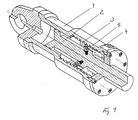
- a hydraulic cylinder 1 is shown in quarter section, which here has a second piston 4 on a cylinder or piston rod 2.
- the piston 4 serves to accommodate means 5 against the undesirable method of the cylinder 1 and the cylinder rod 2.
- the means 5 designed here as pawls form at least one circumferentially integrated in the piston 4 ring assembly. At least two, preferably eight, Pawls 5 provided.
- the cylinder grooves 3 are preferably screwed with defined distances from each other. In this groove 3, the pawls 5 engage the at least one ring, as shown in the figure.
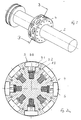
- Fig. 2 shows the piston rod 2 with the second piston 4 and the pawls 5 therein in an isometric view.
- the pawls 5 are here, as also seen in Fig. 2a, retracted.
- the pawls 5 consist essentially of a stamp 5.1, which can be clipped on a holder 5.2 or the like, as well as springs 5.3.
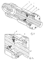
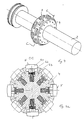
- FIG. 3 and FIG. 3 a show the hydraulic cylinder 1 with pawls 5 extended in the hydraulic cylinder 1 from the piston 4 by the distance ⁇ X.
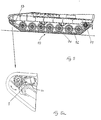
- a drive 10 shown here (one-sided view) consists of a drive wheel 11, rollers 12, a deflection roller 13, a track 14 and support arms, not shown.
- the track 14 is stretched over the guide roller 13.
- the hydraulic cylinder 1 By the hydraulic cylinder 1, the Z-axis, on which the guide roller 13 is attached, moved forward or backward to tension the track or to relax.
- the above-described mechanical procedural safeguarding of the hydraulic cylinder 1 acts by means of pawls 5.
Landscapes
- Engineering & Computer Science (AREA)
- Mechanical Engineering (AREA)
- Fluid Mechanics (AREA)
- Transportation (AREA)
- Combustion & Propulsion (AREA)
- Physics & Mathematics (AREA)
- Chemical & Material Sciences (AREA)
- General Engineering & Computer Science (AREA)
- Actuator (AREA)
- Devices For Conveying Motion By Means Of Endless Flexible Members (AREA)
- Lubricants (AREA)
- Braking Systems And Boosters (AREA)
- Pistons, Piston Rings, And Cylinders (AREA)
- Piles And Underground Anchors (AREA)
Abstract
Description
- Die Erfindung betrifft eine Verfahrabsicherung für einen Hydraulikzylinder beispielsweise einer hydraulischen Raupen- bzw. Kettenspannvorrichtung.
- Insbesondere zum Ablagen / Aufnehmen einer Brücke bzw. eines Brückensegments ist es notwendig, die Raupenkettenspannung hydraulisch anzupassen, damit die Funktionalität des Systems Laufwerk sichergestellt wird.
- Bekannt sind Verfahrsicherungen der Firma Hähnchen, welche unter dem Namen Ratio-Clamp ® vertrieben werden. Diese dienen zur Sicherheit von Mensch und Maschine bei einem Energieausfall oder einer Störung. Hierbei handelt es sich um kraftschlüssige Absicherungen, die über eine Konusverspannung realisiert werden.
- Insbesondere für die Verfahrabsicherung bei den Raupenspannvorrichtungen verwendeten Hydraulikzylindern sind diese kraftschlüssigen Absicherungen nicht ausreichend, um die zu erwartenden Kräfte aufnehmen zu können.
- Die Erfindung stellt sich die Aufgabe, eine Verfahrabsicherung aufzuzeigen, die hohe Kräfte in einfacher Art und Weise aufnehmen kann.
- Gelöst wird die Aufgabe durch die Merkmale des Patentanspruchs 1.
- Der Erfindung liegt die ldee zugrunde, das Verfahren des Hydraulikzylinders mittels verstellbaren Mitteln, beispielsweise mehreren Sperrklinken, im Zylinder selbst zu blockieren. Es ist vorgesehen, das Verstellen der Zylinderstange zu verhindern. Dazu besitzt die im Hydraulikzylinder befindliche Zylinderstange einen weiteren Kolben. Dieser dient zur Aufnahme der Mittel, die ringförmig am / im Kolben eingebunden sind. Als ausreichend hat sich in der Praxis eine Ringanordnung der Mittel gezeigt. Es können aber auch mehrere umfangsseitig zwei oder mehrere Ringe bildende Mittel vorgesehen werden.
- Als gleichfalls vorteilhaft hat sich gezeigt, dass eine gleichmäßige Verteilung des / der Mittel im Ring zu bevorzugen ist. Diese Mittel greifen in im Zylinder mit definierten Anständen vorzugsweise eingedrehte ringförmige Nute, um bei einem Systemausfall (z.B. Druckabfall) ein Verfahren des Hydraulikzylinders zu verhindern. Diese einfache doch sehr effektive Lösung gewährleistet einen sicheren Schutz für Mensch und Maschine
- Vorteilhafte Ausführungen sind in weiteren Unteransprüchen aufgeführt.
- Damit ist die Lösung resistent gegen Erschütterungen, ermöglicht eine formschlüssige Sicherung sowie die Aufnahme größerer Kräfte bei einer kompakten Bauweise.
- Der Einsatz beschränkt sich nicht nur auf Kettenspannvorrichtungen. Weitere Einsatzmöglichkeiten sind Fahrstühle, Metalldruckgussmaschinen, Werkzeugmaschinen, Pressen etc., d.h., bei mit Hydraulikzylindern betriebenen Systemen, bei denen bei einem Energieausfall (beabsichtigt oder unbeabsichtigt), einer Funktionsstörung oder durch andere auch äußere Einflüsse die Sicherheit von Mensch und Maschine bzw. die Funktionalität gewährleistet werden muss.
- Anhand eines Ausführungsbeispiels mit Zeichnung soll die Erfindung näher erläutert werden. Es zeigt:
- Fig. 1
- einen Hydraulikzylinder im Viertelschnitt mit eingefahrenen Mitteln,
- Fig. 2
- die Kolbenstange aus Fig. 1 in isometrischer Darstellung,
- Fig. 2a
- die Schnittansicht B-B aus Fig. 2,
- Fig.3
- der Hydraulikzylinder aus Fig. 1 im Viertelschnitt mit ausgefahrenen Mitteln,
- Fig. 3a
- eine vergrößerte Darstellung aus Fig. 3,
- Fig. 4
- die Kolbenstange aus Fig. 3 in isometrischer Darstellung,
- Fig. 4a
- die Schnittansicht C-C aus Fig. 4,
- Fig. 5
- in einer Prinzipdarstellung einen Systemaufbau eines Laufwerks als ein Anwendungsbeispiel,
- Fig. 5a
- eine vergrößerte Darstellung aus Fig. 5.
- In Fig. 1 ist ein Hydraulikzylinder 1 im Viertelschnitt dargestellt, welcher hier an einer Zylinder- bzw. Kolbenstange 2 einen zweiten Kolben 4 aufweist. Der Kolben 4 dient zur Aufnahme von Mitteln 5 gegen das unerwünschte Verfahren des Zylinders 1 bzw. der Zylinderstange 2. Die hier als Sperrklinken ausgeführten Mittel 5 bilden wenigstens eine umfangsseitig im Kolben 4 eingebundene Ringanordnung. Dabei sind wenigstens zwei, vorzugsweise acht, Sperrklinken 5 vorgesehen. Im Zylinder sind Nuten 3 mit definierten Abständen voneinander vorzugsweise eingedreht. In diese Nut 3 greifen die Sperrklinken 5 des wenigstens einen Ringes, wie in der Figur dargestellt.
- Fig. 2 zeigt die Kolbenstange 2 mit dem zweiten Kolben 4 und den darin befindlichen Sperrklinken 5 in einer isometrischen Darstellung. Die Sperrklinken 5 sind hier, wie auch in Fig. 2a erkennbar, eingefahren. Die Sperrklinken 5 bestehen im Wesentlichen aus einem Stempel 5.1, der auf einem Halter 5.2 aufgeklipst oder dergleichen werden kann, sowie Federn 5.3.
- Fig. 3 und Fig. 3a zeigen den Hydraulikzylinder 1 mit im Hydraulikzylinder 1 aus dem Koben 4 um den Weg Δ X ausgefahrenen Sperrklinken 5.
- Die Darstellung der aus dem Kolben 4 ausgefahrenen Sperrklinken 5 spiegelt sich in den Fig. 4 und 4a wieder.
- Im gesamten Kolbenstangenraum befinde sich Hydrauliköl, welches durch Bohrungen (nicht näher dargestellt) in den Kolben 4 strömen kann. In diesem Raum wird ein Druck aufgebaut, durch den sichergestellt ist, dass Federn 5.3 der Sperrklinken 5 durch Stempel 5.1 in ihre Nulllage gebracht werden und ein Freigang der Sperrklinken 5 sichergestellt ist . Bei einem Druckverlust im Kolben 4 expandieren die Federn 5.3 und schieben die Sperrklinken 5 über die Stempel 5.1 beim Verfahren der Zylinderstange 2 in die nächst mögliche Nut 3 des Zylinders 1. Vor dem erneuten Verfahren der Zylinderstange 2 werden die Sperrklinken 5 durch einen entsprechenden hydraulischen Druck wieder eingefahren und der Hydraulikzylinder 1 kann wieder beliebig verfahren werden.
- Ein Anwendungsbeispiel ist in Fig. 5 und näher in Fig. 5a aufgezeigt. Ein hier dargestelltes Laufwerk 10 (einseitige Betrachtung) besteht aus einem Antriebsrad 11, Laufrollen 12, einer Umlenkrolle 13, einer Gleiskette 14 sowie nicht näher dargestellten Tragarmen. Die Gleiskette 14 wird über die Umlenkrolle 13 gespannt. Durch den Hydraulikzylinder 1 wird die Z-Achse, an der die Umlenkrolle 13 befestigt ist, nach vorne bzw. nach hinten verfahren, um die Gleiskette zu spannen bzw. zu entspannen. Bei einem Energieausfall oder dergleichen wirkt die vorab beschriebene mechanische Verfahrabsicherung des Hydraulikzylinders 1 mittels Sperrklinken 5.
Claims (6)
- Hydraulikzylinder (1), aufweisend wenigstens eine Zylinderstange (2), dadurch gekennzeichnet, dass an der Zylinderstange (2) ein weiterer Kolben (4) eingebunden ist, welcher zur Aufnahme von Mitteln (5) gegen ungewolltes Verfahren der Zylinderstange (2) dient, wobei die Mittel (5) bei einer Druckänderung eines im Raum der Zylinderstange (2) enthaltenen Hydrauliköls in Nute (3) im Hydraulikzylinder (1) greifen und in diese verstellt werden.
- Hydraulikzylinder nach Anspruch 1, dadurch gekennzeichnet, dass die Mittel (5) eine oder mehrere Ringe am /im Kolben (4) bilden.
- Hydraulikzylinder nach Anspruch 1 oder 2, dadurch gekennzeichnet, dass die Mittel (5) Sperrklinken sind.
- Hydraulikzylinder nach Anspruch 3, dadurch gekennzeichnet, dass die Sperrklinken (5) im Wesentlichen aus einem Stempel (5.1), einem Halter (5.2) für den Stempel (5.1) sowie Federn (5.3) besteht.
- Hydraulikzylinder nach Anspruch 3 oder 4, dadurch gekennzeichnet, dass wenigstens zwei, vorzugsweise acht Stempel (5) umfangsseitig verteilt eine Ringanordnung am / im Kolben (4) bilden.
- Laufwerk (10), bestehend aus wenigstens einem Antriebsrad (11), Laufrollen (12), einer Umlenkrolle (13) sowie einer Gleiskette (14) mit wenigstens einem Hydraulikzylinder (1) nach einem der Ansprüche 1 bis 5.
Applications Claiming Priority (1)
| Application Number | Priority Date | Filing Date | Title |
|---|---|---|---|
| DE102004049854A DE102004049854B3 (de) | 2004-10-13 | 2004-10-13 | Verfahrabsicherung für einen Hydraulikzylinder |
Publications (2)
| Publication Number | Publication Date |
|---|---|
| EP1647722A1 true EP1647722A1 (de) | 2006-04-19 |
| EP1647722B1 EP1647722B1 (de) | 2007-12-05 |
Family
ID=35520987
Family Applications (1)
| Application Number | Title | Priority Date | Filing Date |
|---|---|---|---|
| EP05019508A Expired - Lifetime EP1647722B1 (de) | 2004-10-13 | 2005-09-08 | Verfahrabsicherung für einen Hydraulikzylinder |
Country Status (5)
| Country | Link |
|---|---|
| EP (1) | EP1647722B1 (de) |
| AT (1) | ATE380298T1 (de) |
| DE (2) | DE102004049854B3 (de) |
| DK (1) | DK1647722T3 (de) |
| ES (1) | ES2298900T3 (de) |
Cited By (3)
| Publication number | Priority date | Publication date | Assignee | Title |
|---|---|---|---|---|
| WO2016176627A3 (en) * | 2015-04-29 | 2017-01-26 | Clark Equipment Company | Track tensioner |
| WO2022040739A1 (en) * | 2020-08-25 | 2022-03-03 | The Dynamic Engineering Solution Pty Ltd | Track tensioning system |
| CN114542542A (zh) * | 2020-11-19 | 2022-05-27 | 波音公司 | 致动器 |
Families Citing this family (3)
| Publication number | Priority date | Publication date | Assignee | Title |
|---|---|---|---|---|
| ES2863252T3 (es) | 2016-12-28 | 2021-10-11 | Henning Fuhrmann | Dispositivo de cilindro de trabajo con al menos una unidad de cilindro de trabajo con bloqueo mecánico de posición, así como un procedimiento para su operación |
| DE102016125782A1 (de) * | 2016-12-28 | 2018-06-28 | Henning Fuhrmann | Arbeitszylinder-Vorrichtung mit wenigstens einer Arbeitszylinder-Einheit mit mechanischer Positionssicherung sowie Verfahren zu ihrem Betrieb |
| WO2024186335A1 (en) | 2023-03-07 | 2024-09-12 | Herzog Railroad Services, Inc. | Conveyor tensioner system |
Citations (5)
| Publication number | Priority date | Publication date | Assignee | Title |
|---|---|---|---|---|
| US3813065A (en) * | 1969-06-23 | 1974-05-28 | Decoto Aircraft Inc | Locking mechanisms and actuator assemblies of coaxial locked remotely at selected locations after motions of a nearly complete circumferential one piece chamfered locking ring |
| DE3232322A1 (de) * | 1982-08-31 | 1984-03-01 | Krauss-Maffei AG, 8000 München | Hydraulische kettenspannvorrichtung |
| DE8803529U1 (de) * | 1988-03-16 | 1988-04-28 | AHP Gerhard Merkle, 7801 March | Druckmittel-Zylinder mit Verriegelungsvorrichtung |
| US4893883A (en) * | 1988-03-02 | 1990-01-16 | Caterpillar Inc. | Belt tension control system |
| US20040182235A1 (en) * | 2003-03-17 | 2004-09-23 | Hart Kenneth E. | Locking hydraulic actuator |
-
2004
- 2004-10-13 DE DE102004049854A patent/DE102004049854B3/de not_active Expired - Fee Related
-
2005
- 2005-09-08 DK DK05019508T patent/DK1647722T3/da active
- 2005-09-08 DE DE502005002143T patent/DE502005002143D1/de not_active Expired - Lifetime
- 2005-09-08 ES ES05019508T patent/ES2298900T3/es not_active Expired - Lifetime
- 2005-09-08 AT AT05019508T patent/ATE380298T1/de not_active IP Right Cessation
- 2005-09-08 EP EP05019508A patent/EP1647722B1/de not_active Expired - Lifetime
Patent Citations (5)
| Publication number | Priority date | Publication date | Assignee | Title |
|---|---|---|---|---|
| US3813065A (en) * | 1969-06-23 | 1974-05-28 | Decoto Aircraft Inc | Locking mechanisms and actuator assemblies of coaxial locked remotely at selected locations after motions of a nearly complete circumferential one piece chamfered locking ring |
| DE3232322A1 (de) * | 1982-08-31 | 1984-03-01 | Krauss-Maffei AG, 8000 München | Hydraulische kettenspannvorrichtung |
| US4893883A (en) * | 1988-03-02 | 1990-01-16 | Caterpillar Inc. | Belt tension control system |
| DE8803529U1 (de) * | 1988-03-16 | 1988-04-28 | AHP Gerhard Merkle, 7801 March | Druckmittel-Zylinder mit Verriegelungsvorrichtung |
| US20040182235A1 (en) * | 2003-03-17 | 2004-09-23 | Hart Kenneth E. | Locking hydraulic actuator |
Cited By (8)
| Publication number | Priority date | Publication date | Assignee | Title |
|---|---|---|---|---|
| WO2016176627A3 (en) * | 2015-04-29 | 2017-01-26 | Clark Equipment Company | Track tensioner |
| US10113656B2 (en) | 2015-04-29 | 2018-10-30 | Clark Equipment Company | Track tensioner |
| WO2022040739A1 (en) * | 2020-08-25 | 2022-03-03 | The Dynamic Engineering Solution Pty Ltd | Track tensioning system |
| GB2613518A (en) * | 2020-08-25 | 2023-06-07 | The Dynamic Eng Solution Pty Ltd | Track tensioning system |
| US12612125B2 (en) | 2020-08-25 | 2026-04-28 | The Dynamic Engineering Solution Pty Ltd | Track tensioning system |
| CN114542542A (zh) * | 2020-11-19 | 2022-05-27 | 波音公司 | 致动器 |
| JP2022084547A (ja) * | 2020-11-19 | 2022-06-07 | ザ・ボーイング・カンパニー | アクチュエータ |
| US20220205466A1 (en) * | 2020-11-19 | 2022-06-30 | The Boeing Company | Actuator |
Also Published As
| Publication number | Publication date |
|---|---|
| EP1647722B1 (de) | 2007-12-05 |
| DE102004049854B3 (de) | 2006-04-27 |
| ES2298900T3 (es) | 2008-05-16 |
| DK1647722T3 (da) | 2008-04-14 |
| DE502005002143D1 (de) | 2008-01-17 |
| ATE380298T1 (de) | 2007-12-15 |
Similar Documents
| Publication | Publication Date | Title |
|---|---|---|
| DE3723494C2 (de) | Spannvorrichtung | |
| DE60122218T2 (de) | Befestigungsvorrichtung | |
| DE3142279C2 (de) | Haltevorrichtung zum reibschlüssigen Festhalten eines längsbeweglichen Bauteils | |
| DE2632748A1 (de) | Druckmittelbetaetigte schiebevorrichtung | |
| DE102009043034A1 (de) | Vorgespannter hydraulischer Antrieb mit drehzahlvariabler Pumpe | |
| DE202012002850U1 (de) | Schwenkmodul-Kombination für gespannte Werkstücke | |
| DE19546356A1 (de) | Linearaktuatoren | |
| EP1106276A2 (de) | Presswerkzeug zum Verpressen von rotationssymmetrischen Hohlkörpern | |
| DE3728418C2 (de) | ||
| EP1647722B1 (de) | Verfahrabsicherung für einen Hydraulikzylinder | |
| DE2622593A1 (de) | Hydraulisches system fuer einen kreiselbrecher | |
| DE3151275A1 (de) | Befestigungsvorrichtung fuer werkzeuge | |
| DE2841952A1 (de) | Presse wie schmiedepresse o.dgl. | |
| DE4330833A1 (de) | Vorrichtung zum Spannen und Abfedern des Leitrades von Kettenfahrzeugen | |
| DE4025929C2 (de) | Spannvorrichtung für das Leitrad von Kettenfahrzeugen | |
| DE2655284A1 (de) | Pneumatisch oder hydraulisch und einseitig oder doppelt beaufschlagbare kolben-zylinder-vorrichtung | |
| EP0058878B1 (de) | Vorrichtung für die Drehung hängender Lasten | |
| DE3048229C2 (de) | Rückschlagventil für Grubenausbaustempel | |
| DE102010037267A1 (de) | Vorrichtung zum Halten und Transportieren eines Reifengürtels für die Herstellung eines Fahrzeugreifens | |
| DE10004656C1 (de) | Wellenricht- und -härtemaschine | |
| DE1580384A1 (de) | Vorrichtung zur Blockierung des Antriebsrades von Raupenfahrzeugen | |
| DE4444498A1 (de) | Schmiedemaschine | |
| EP0298017B1 (de) | Radialpresse | |
| DE2032874A1 (de) | ||
| DE1807158A1 (de) | Doppeltwirkender Hydraulikzylinder fuer teleskopartig ausschiebbare Kranausleger |
Legal Events
| Date | Code | Title | Description |
|---|---|---|---|
| PUAI | Public reference made under article 153(3) epc to a published international application that has entered the european phase |
Free format text: ORIGINAL CODE: 0009012 |
|
| 17P | Request for examination filed |
Effective date: 20060208 |
|
| AK | Designated contracting states |
Kind code of ref document: A1 Designated state(s): AT BE BG CH CY CZ DE DK EE ES FI FR GB GR HU IE IS IT LI LT LU LV MC NL PL PT RO SE SI SK TR |
|
| AX | Request for extension of the european patent |
Extension state: AL BA HR MK YU |
|
| AKX | Designation fees paid |
Designated state(s): AT BE BG CH CY CZ DE DK EE ES FI FR GB GR HU IE IS IT LI LT LU LV MC NL PL PT RO SE SI SK TR |
|
| GRAP | Despatch of communication of intention to grant a patent |
Free format text: ORIGINAL CODE: EPIDOSNIGR1 |
|
| GRAS | Grant fee paid |
Free format text: ORIGINAL CODE: EPIDOSNIGR3 |
|
| GRAA | (expected) grant |
Free format text: ORIGINAL CODE: 0009210 |
|
| AK | Designated contracting states |
Kind code of ref document: B1 Designated state(s): AT BE BG CH CY CZ DE DK EE ES FI FR GB GR HU IE IS IT LI LT LU LV MC NL PL PT RO SE SI SK TR |
|
| REG | Reference to a national code |
Ref country code: GB Ref legal event code: FG4D Free format text: NOT ENGLISH |
|
| REG | Reference to a national code |
Ref country code: IE Ref legal event code: FG4D Free format text: LANGUAGE OF EP DOCUMENT: GERMAN |
|
| REG | Reference to a national code |
Ref country code: CH Ref legal event code: EP |
|
| REF | Corresponds to: |
Ref document number: 502005002143 Country of ref document: DE Date of ref document: 20080117 Kind code of ref document: P |
|
| REG | Reference to a national code |
Ref country code: GR Ref legal event code: EP Ref document number: 20080400579 Country of ref document: GR |
|
| REG | Reference to a national code |
Ref country code: SE Ref legal event code: TRGR |
|
| GBT | Gb: translation of ep patent filed (gb section 77(6)(a)/1977) |
Effective date: 20080312 |
|
| REG | Reference to a national code |
Ref country code: DK Ref legal event code: T3 |
|
| REG | Reference to a national code |
Ref country code: CH Ref legal event code: NV Representative=s name: OK PAT AG PATENTE MARKEN LIZENZEN |
|
| REG | Reference to a national code |
Ref country code: ES Ref legal event code: FG2A Ref document number: 2298900 Country of ref document: ES Kind code of ref document: T3 |
|
| PG25 | Lapsed in a contracting state [announced via postgrant information from national office to epo] |
Ref country code: SI Free format text: LAPSE BECAUSE OF FAILURE TO SUBMIT A TRANSLATION OF THE DESCRIPTION OR TO PAY THE FEE WITHIN THE PRESCRIBED TIME-LIMIT Effective date: 20071205 Ref country code: PL Free format text: LAPSE BECAUSE OF FAILURE TO SUBMIT A TRANSLATION OF THE DESCRIPTION OR TO PAY THE FEE WITHIN THE PRESCRIBED TIME-LIMIT Effective date: 20071205 Ref country code: LT Free format text: LAPSE BECAUSE OF FAILURE TO SUBMIT A TRANSLATION OF THE DESCRIPTION OR TO PAY THE FEE WITHIN THE PRESCRIBED TIME-LIMIT Effective date: 20071205 Ref country code: LV Free format text: LAPSE BECAUSE OF FAILURE TO SUBMIT A TRANSLATION OF THE DESCRIPTION OR TO PAY THE FEE WITHIN THE PRESCRIBED TIME-LIMIT Effective date: 20071205 |
|
| PG25 | Lapsed in a contracting state [announced via postgrant information from national office to epo] |
Ref country code: IS Free format text: LAPSE BECAUSE OF FAILURE TO SUBMIT A TRANSLATION OF THE DESCRIPTION OR TO PAY THE FEE WITHIN THE PRESCRIBED TIME-LIMIT Effective date: 20080405 Ref country code: CZ Free format text: LAPSE BECAUSE OF FAILURE TO SUBMIT A TRANSLATION OF THE DESCRIPTION OR TO PAY THE FEE WITHIN THE PRESCRIBED TIME-LIMIT Effective date: 20071205 |
|
| ET | Fr: translation filed | ||
| PG25 | Lapsed in a contracting state [announced via postgrant information from national office to epo] |
Ref country code: SK Free format text: LAPSE BECAUSE OF FAILURE TO SUBMIT A TRANSLATION OF THE DESCRIPTION OR TO PAY THE FEE WITHIN THE PRESCRIBED TIME-LIMIT Effective date: 20071205 Ref country code: RO Free format text: LAPSE BECAUSE OF FAILURE TO SUBMIT A TRANSLATION OF THE DESCRIPTION OR TO PAY THE FEE WITHIN THE PRESCRIBED TIME-LIMIT Effective date: 20071205 |
|
| PG25 | Lapsed in a contracting state [announced via postgrant information from national office to epo] |
Ref country code: PT Free format text: LAPSE BECAUSE OF FAILURE TO SUBMIT A TRANSLATION OF THE DESCRIPTION OR TO PAY THE FEE WITHIN THE PRESCRIBED TIME-LIMIT Effective date: 20080505 |
|
| REG | Reference to a national code |
Ref country code: IE Ref legal event code: FD4D |
|
| PLBE | No opposition filed within time limit |
Free format text: ORIGINAL CODE: 0009261 |
|
| STAA | Information on the status of an ep patent application or granted ep patent |
Free format text: STATUS: NO OPPOSITION FILED WITHIN TIME LIMIT |
|
| PG25 | Lapsed in a contracting state [announced via postgrant information from national office to epo] |
Ref country code: IE Free format text: LAPSE BECAUSE OF FAILURE TO SUBMIT A TRANSLATION OF THE DESCRIPTION OR TO PAY THE FEE WITHIN THE PRESCRIBED TIME-LIMIT Effective date: 20071205 |
|
| 26N | No opposition filed |
Effective date: 20080908 |
|
| BERE | Be: lapsed |
Owner name: RHEINMETALL LANDSYSTEME G.M.B.H. Effective date: 20080930 |
|
| PG25 | Lapsed in a contracting state [announced via postgrant information from national office to epo] |
Ref country code: EE Free format text: LAPSE BECAUSE OF FAILURE TO SUBMIT A TRANSLATION OF THE DESCRIPTION OR TO PAY THE FEE WITHIN THE PRESCRIBED TIME-LIMIT Effective date: 20071205 Ref country code: BG Free format text: LAPSE BECAUSE OF FAILURE TO SUBMIT A TRANSLATION OF THE DESCRIPTION OR TO PAY THE FEE WITHIN THE PRESCRIBED TIME-LIMIT Effective date: 20080305 Ref country code: MC Free format text: LAPSE BECAUSE OF NON-PAYMENT OF DUE FEES Effective date: 20080930 |
|
| PG25 | Lapsed in a contracting state [announced via postgrant information from national office to epo] |
Ref country code: CY Free format text: LAPSE BECAUSE OF FAILURE TO SUBMIT A TRANSLATION OF THE DESCRIPTION OR TO PAY THE FEE WITHIN THE PRESCRIBED TIME-LIMIT Effective date: 20071205 Ref country code: BE Free format text: LAPSE BECAUSE OF NON-PAYMENT OF DUE FEES Effective date: 20080930 |
|
| PG25 | Lapsed in a contracting state [announced via postgrant information from national office to epo] |
Ref country code: AT Free format text: LAPSE BECAUSE OF NON-PAYMENT OF DUE FEES Effective date: 20080908 |
|
| PG25 | Lapsed in a contracting state [announced via postgrant information from national office to epo] |
Ref country code: HU Free format text: LAPSE BECAUSE OF FAILURE TO SUBMIT A TRANSLATION OF THE DESCRIPTION OR TO PAY THE FEE WITHIN THE PRESCRIBED TIME-LIMIT Effective date: 20080606 Ref country code: LU Free format text: LAPSE BECAUSE OF NON-PAYMENT OF DUE FEES Effective date: 20080908 |
|
| PGFP | Annual fee paid to national office [announced via postgrant information from national office to epo] |
Ref country code: FI Payment date: 20100914 Year of fee payment: 6 Ref country code: IT Payment date: 20100922 Year of fee payment: 6 Ref country code: TR Payment date: 20100824 Year of fee payment: 6 |
|
| PGFP | Annual fee paid to national office [announced via postgrant information from national office to epo] |
Ref country code: GR Payment date: 20100928 Year of fee payment: 6 |
|
| PGFP | Annual fee paid to national office [announced via postgrant information from national office to epo] |
Ref country code: DK Payment date: 20100913 Year of fee payment: 6 Ref country code: NL Payment date: 20100916 Year of fee payment: 6 |
|
| REG | Reference to a national code |
Ref country code: NL Ref legal event code: V1 Effective date: 20120401 |
|
| REG | Reference to a national code |
Ref country code: DK Ref legal event code: EBP |
|
| REG | Reference to a national code |
Ref country code: GR Ref legal event code: ML Ref document number: 20080400579 Country of ref document: GR Effective date: 20120403 |
|
| PG25 | Lapsed in a contracting state [announced via postgrant information from national office to epo] |
Ref country code: IT Free format text: LAPSE BECAUSE OF NON-PAYMENT OF DUE FEES Effective date: 20110908 Ref country code: FI Free format text: LAPSE BECAUSE OF NON-PAYMENT OF DUE FEES Effective date: 20110908 |
|
| PG25 | Lapsed in a contracting state [announced via postgrant information from national office to epo] |
Ref country code: NL Free format text: LAPSE BECAUSE OF NON-PAYMENT OF DUE FEES Effective date: 20120401 |
|
| PG25 | Lapsed in a contracting state [announced via postgrant information from national office to epo] |
Ref country code: GR Free format text: LAPSE BECAUSE OF NON-PAYMENT OF DUE FEES Effective date: 20120403 |
|
| PG25 | Lapsed in a contracting state [announced via postgrant information from national office to epo] |
Ref country code: DK Free format text: LAPSE BECAUSE OF NON-PAYMENT OF DUE FEES Effective date: 20110930 |
|
| PG25 | Lapsed in a contracting state [announced via postgrant information from national office to epo] |
Ref country code: TR Free format text: LAPSE BECAUSE OF NON-PAYMENT OF DUE FEES Effective date: 20110908 |
|
| REG | Reference to a national code |
Ref country code: FR Ref legal event code: PLFP Year of fee payment: 12 |
|
| PGFP | Annual fee paid to national office [announced via postgrant information from national office to epo] |
Ref country code: CH Payment date: 20160920 Year of fee payment: 12 Ref country code: GB Payment date: 20160920 Year of fee payment: 12 Ref country code: DE Payment date: 20160921 Year of fee payment: 12 |
|
| PGFP | Annual fee paid to national office [announced via postgrant information from national office to epo] |
Ref country code: SE Payment date: 20160920 Year of fee payment: 12 Ref country code: FR Payment date: 20160921 Year of fee payment: 12 |
|
| PGFP | Annual fee paid to national office [announced via postgrant information from national office to epo] |
Ref country code: ES Payment date: 20160916 Year of fee payment: 12 |
|
| REG | Reference to a national code |
Ref country code: DE Ref legal event code: R119 Ref document number: 502005002143 Country of ref document: DE |
|
| REG | Reference to a national code |
Ref country code: CH Ref legal event code: PL |
|
| REG | Reference to a national code |
Ref country code: SE Ref legal event code: EUG |
|
| GBPC | Gb: european patent ceased through non-payment of renewal fee |
Effective date: 20170908 |
|
| REG | Reference to a national code |
Ref country code: FR Ref legal event code: ST Effective date: 20180531 |
|
| PG25 | Lapsed in a contracting state [announced via postgrant information from national office to epo] |
Ref country code: LI Free format text: LAPSE BECAUSE OF NON-PAYMENT OF DUE FEES Effective date: 20170930 Ref country code: CH Free format text: LAPSE BECAUSE OF NON-PAYMENT OF DUE FEES Effective date: 20170930 Ref country code: GB Free format text: LAPSE BECAUSE OF NON-PAYMENT OF DUE FEES Effective date: 20170908 Ref country code: DE Free format text: LAPSE BECAUSE OF NON-PAYMENT OF DUE FEES Effective date: 20180404 |
|
| PG25 | Lapsed in a contracting state [announced via postgrant information from national office to epo] |
Ref country code: FR Free format text: LAPSE BECAUSE OF NON-PAYMENT OF DUE FEES Effective date: 20171002 |
|
| REG | Reference to a national code |
Ref country code: ES Ref legal event code: FD2A Effective date: 20181024 |
|
| PG25 | Lapsed in a contracting state [announced via postgrant information from national office to epo] |
Ref country code: ES Free format text: LAPSE BECAUSE OF NON-PAYMENT OF DUE FEES Effective date: 20170909 |
|
| PG25 | Lapsed in a contracting state [announced via postgrant information from national office to epo] |
Ref country code: SE Free format text: LAPSE BECAUSE OF NON-PAYMENT OF DUE FEES Effective date: 20170909 |