EP1647390B1 - Canal à double flux d'écoulement réglable pour une tête d'extrusion - Google Patents
Canal à double flux d'écoulement réglable pour une tête d'extrusion Download PDFInfo
- Publication number
- EP1647390B1 EP1647390B1 EP05109338A EP05109338A EP1647390B1 EP 1647390 B1 EP1647390 B1 EP 1647390B1 EP 05109338 A EP05109338 A EP 05109338A EP 05109338 A EP05109338 A EP 05109338A EP 1647390 B1 EP1647390 B1 EP 1647390B1
- Authority
- EP
- European Patent Office
- Prior art keywords
- flow
- extruder head
- centerline
- divertor
- transition section
- Prior art date
- Legal status (The legal status is an assumption and is not a legal conclusion. Google has not performed a legal analysis and makes no representation as to the accuracy of the status listed.)
- Expired - Fee Related
Links
Images

Classifications
-
- B—PERFORMING OPERATIONS; TRANSPORTING
- B29—WORKING OF PLASTICS; WORKING OF SUBSTANCES IN A PLASTIC STATE IN GENERAL
- B29C—SHAPING OR JOINING OF PLASTICS; SHAPING OF MATERIAL IN A PLASTIC STATE, NOT OTHERWISE PROVIDED FOR; AFTER-TREATMENT OF THE SHAPED PRODUCTS, e.g. REPAIRING
- B29C48/00—Extrusion moulding, i.e. expressing the moulding material through a die or nozzle which imparts the desired form; Apparatus therefor
- B29C48/25—Component parts, details or accessories; Auxiliary operations
- B29C48/36—Means for plasticising or homogenising the moulding material or forcing it through the nozzle or die
- B29C48/50—Details of extruders
- B29C48/695—Flow dividers, e.g. breaker plates
-
- B—PERFORMING OPERATIONS; TRANSPORTING
- B29—WORKING OF PLASTICS; WORKING OF SUBSTANCES IN A PLASTIC STATE IN GENERAL
- B29C—SHAPING OR JOINING OF PLASTICS; SHAPING OF MATERIAL IN A PLASTIC STATE, NOT OTHERWISE PROVIDED FOR; AFTER-TREATMENT OF THE SHAPED PRODUCTS, e.g. REPAIRING
- B29C48/00—Extrusion moulding, i.e. expressing the moulding material through a die or nozzle which imparts the desired form; Apparatus therefor
- B29C48/03—Extrusion moulding, i.e. expressing the moulding material through a die or nozzle which imparts the desired form; Apparatus therefor characterised by the shape of the extruded material at extrusion
- B29C48/07—Flat, e.g. panels
-
- B—PERFORMING OPERATIONS; TRANSPORTING
- B29—WORKING OF PLASTICS; WORKING OF SUBSTANCES IN A PLASTIC STATE IN GENERAL
- B29C—SHAPING OR JOINING OF PLASTICS; SHAPING OF MATERIAL IN A PLASTIC STATE, NOT OTHERWISE PROVIDED FOR; AFTER-TREATMENT OF THE SHAPED PRODUCTS, e.g. REPAIRING
- B29C48/00—Extrusion moulding, i.e. expressing the moulding material through a die or nozzle which imparts the desired form; Apparatus therefor
- B29C48/25—Component parts, details or accessories; Auxiliary operations
- B29C48/30—Extrusion nozzles or dies
- B29C48/305—Extrusion nozzles or dies having a wide opening, e.g. for forming sheets
-
- B—PERFORMING OPERATIONS; TRANSPORTING
- B29—WORKING OF PLASTICS; WORKING OF SUBSTANCES IN A PLASTIC STATE IN GENERAL
- B29C—SHAPING OR JOINING OF PLASTICS; SHAPING OF MATERIAL IN A PLASTIC STATE, NOT OTHERWISE PROVIDED FOR; AFTER-TREATMENT OF THE SHAPED PRODUCTS, e.g. REPAIRING
- B29C48/00—Extrusion moulding, i.e. expressing the moulding material through a die or nozzle which imparts the desired form; Apparatus therefor
- B29C48/03—Extrusion moulding, i.e. expressing the moulding material through a die or nozzle which imparts the desired form; Apparatus therefor characterised by the shape of the extruded material at extrusion
- B29C48/06—Rod-shaped
-
- B—PERFORMING OPERATIONS; TRANSPORTING
- B29—WORKING OF PLASTICS; WORKING OF SUBSTANCES IN A PLASTIC STATE IN GENERAL
- B29C—SHAPING OR JOINING OF PLASTICS; SHAPING OF MATERIAL IN A PLASTIC STATE, NOT OTHERWISE PROVIDED FOR; AFTER-TREATMENT OF THE SHAPED PRODUCTS, e.g. REPAIRING
- B29C48/00—Extrusion moulding, i.e. expressing the moulding material through a die or nozzle which imparts the desired form; Apparatus therefor
- B29C48/03—Extrusion moulding, i.e. expressing the moulding material through a die or nozzle which imparts the desired form; Apparatus therefor characterised by the shape of the extruded material at extrusion
- B29C48/12—Articles with an irregular circumference when viewed in cross-section, e.g. window profiles
-
- B—PERFORMING OPERATIONS; TRANSPORTING
- B29—WORKING OF PLASTICS; WORKING OF SUBSTANCES IN A PLASTIC STATE IN GENERAL
- B29K—INDEXING SCHEME ASSOCIATED WITH SUBCLASSES B29B, B29C OR B29D, RELATING TO MOULDING MATERIALS OR TO MATERIALS FOR MOULDS, REINFORCEMENTS, FILLERS OR PREFORMED PARTS, e.g. INSERTS
- B29K2021/00—Use of unspecified rubbers as moulding material
-
- B—PERFORMING OPERATIONS; TRANSPORTING
- B29—WORKING OF PLASTICS; WORKING OF SUBSTANCES IN A PLASTIC STATE IN GENERAL
- B29L—INDEXING SCHEME ASSOCIATED WITH SUBCLASS B29C, RELATING TO PARTICULAR ARTICLES
- B29L2030/00—Pneumatic or solid tyres or parts thereof
- B29L2030/002—Treads
Definitions
- This invention relates to an apparatus for directing the flow of elastomeric material through an extruder head.
- extruder having a heated barrel and a screw that provides shear energy to the material to be plasticized is well known. As the material is heated, it generally converts from a solid pellet or strip form into a strip of plasticized material at the end of the screw tip that projects the material into an extruder head.
- This extruder head generally has a single flow channel having a straight flow path that directs the plasticized material through the extruder head to an outlet or discharge die that forms the material into the proper predetermined cross-sectional profile.
- EP-A- 1186397 or US-A- 2004/0185132 describe an extruder head according to the preamble of claim 1.
- a similar extruder head is also known from WO-A- 99/22927 .
- the invention provides in a first aspect an extruder head for forming simultaneously two or more elastomeric strips of predetermined cross-sectional profiles from a material according to claim 1.
- the invention provides in a second aspect a method of forming simultaneously two or more elastomeric strips of predetermined cross-sectional profiles from a material according to claim 9.
- an extruder (partially shown) has an extruder screw 2 with an extruder screw tip 4 enclosed in an extruder barrel 3. Attached to the extruder barrel is an extruder head 5.
- the extruder head has a flow channel 10 for receiving plastic or elastomeric material such as rubber.
- the flow channel 10 is further divided downstream into two flow channels 40, 50 for preforming the flow.
- Each channel 40, 50 has an outlet end for discharging the plasticized material through a die for forming the profile of the elastomeric strip to be produced. This die is commonly referred to as a profile die 60.
- the mass flow is divided into two flow channels 40, 50.
- the flow channels are oriented at an angle ⁇ in the range of 30-60 degrees, and preferably 50 degrees.
- ⁇ in the range of 30-60 degrees, and preferably 50 degrees.
- the material travels faster along the inner walls 70 than along the outside walls 72. Further, more of the mass of the material is concentrated along the inner wall 70.
- the angled flow channel results in an uneven mass and velocity distribution, with a faster flowing mass more concentrated along the inner wall.
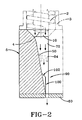
- a transition section 80 is added prior to the flow discharge section 90.
- the transition section 80 comprises inner and outer flat sidewalls 82, 84 wherein the sidewalls entering and exiting the transition area are curved.
- the transition section 80 has a length L and a width W. Preferably the width about equals the length, and has a sufficient length L sized to stabilize the flow into a uniform mass profile. Thus the flow in the transition area is parallel to the inlet flow and the discharge flow.
- the width W is the distance between the inner sidewall 82 and the outer sidewall 84.
- the transition area 80 Since a disproportionate amount of mass of the material entering the transition area is near the inner wall 82, the transition area 80 functions to shift the mass towards the outer wall 84, so that the center of mass of the flow is centered in alignment with the downstream flow divertor.
- the transition section 80 has a centerline which is slightly offset towards the outer wall from the centerline of the flow discharge channel. The effect of the offset transition centerline is to shift the mass of the flow towards the outer wall, and thus into a more uniform distribution.
- the amount of centerline transition offset may depend upon the flow characteristics of the particular material selected. Typically for rubber, the offset may be in the range of 1 to 6 mm.
- a flow divertor 100 Centered with each flow discharge channel is a flow divertor 100, which is preferably shaped like a wing, having sweeping leading edges 102. Each flow divertor is preferably symmetrical in design about its centerline. The flow divertor 100 functions to spread out the material into the desired width prior to flowing into the die 60.
Claims (9)
- Tête d'extrudeuse comprenant une entrée d'écoulement (10) pour la réception d'une matière à extruder ; et un premier et un deuxième canal d'écoulement (40, 50) communiquant avec une extrémité de l'entrée d'écoulement (10) ; dans laquelle chaque canal d'écoulement (40, 50) possède une section de transition (80) possédant des parois latérales (82, 84) et une ligne médiane ; dans laquelle une première section d'évacuation d'écoulement (90) est mise en communication par fluide avec le premier canal d'écoulement (40) et une deuxième section d'évacuation d'écoulement (90) est mise en communication par fluide avec le deuxième canal d'écoulement (50) ; et dans laquelle chaque section d'évacuation d'écoulement (90) possède un élément de déviation (100) en position centrale, l'élément de déviation possédant une ligne médiane ; caractérisé en ce que la ligne médiane de la section de transition (80) est décalée par rapport à la ligne médiane de l'élément de déviation (100).
- Tête d'extrudeuse selon la revendication 1, dans laquelle les parois latérales (82, 84) de la section de transition (80) sont plates et/ou dans laquelle les parois latérales (82, 84), à l'endroit de l'entrée et de la sortie de la section de transition (80), sont courbes.
- Tête d'extrudeuse selon la revendication 1 ou 2, dans laquelle la section de transition (80) possède une longueur (L) qui est suffisante pour stabiliser l'écoulement de la matière à extruder pour obtenir un profil de masse uniforme.
- Tête d'extrudeuse selon au moins une des revendications précédentes, dans laquelle la section de transition (80) possède une longueur (L) et une largeur, la largeur représentant de 90 % à 140 %, de préférence de 95 % à 120 % de la longueur.
- Tête d'extrudeuse selon au moins une des revendications précédentes, dans laquelle l'écoulement de la matière dans la section de transition (80) est parallèle à l'écoulement de la matière dans l'entrée d'écoulement (10) et parallèle à l'écoulement de la matière à la sortie de l'élément de déviation (100).
- Tête d'extrudeuse selon au moins une des revendications précédentes, dans laquelle la ligne médiane de la section de transition (80) est décalée en direction de la paroi latérale externe (80) par rapport à la ligne médiane de l'élément de déviation (100).
- Tête d'extrudeuse selon au moins une des revendications précédentes, dans laquelle le décalage se situe dans la plage de 1 mm à 6 mm.
- Tête d'extrudeuse selon au moins une des revendications précédentes, dans laquelle l'élément de déviation (100) est configuré à la manière d'une aile possédant des bords avant (102) procurant un balayage.
- Procédé pour la formation simultanée de deux bandes élastomères ou plus possédant des profilés prédéterminés en section transversale, à partir d'une matière, le procédé comprenant les étapes consistant à :(a) réceptionner la matière à partir d'une extrudeuse dans un canal (10) ;(b) diviser la matière provenant du canal (10) en un premier et en un deuxième canal d'écoulement angulaire (40, 50) ;(c) redresser l'écoulement de la matière dans une section de transition (80) du premier et du deuxième canal d'écoulement (40, 50) ;(d) disposer le centre de la masse de la matière en alignement avec le centre d'un élément de déviation (100) disposé dans une section d'évacuation (90) en décalant la ligne médiane de la section de transition (80) par rapport à la ligne médiane de l'élément de déviation (100) ; et(e) évacuer la matière de la section d'évacuation (90) dans une filière (60) et/ou dans un gabarit préconformateur.
Applications Claiming Priority (1)
| Application Number | Priority Date | Filing Date | Title |
|---|---|---|---|
| US10/964,010 US20060076703A1 (en) | 2004-10-13 | 2004-10-13 | Double flow channel for an extruder head |
Publications (3)
| Publication Number | Publication Date |
|---|---|
| EP1647390A2 EP1647390A2 (fr) | 2006-04-19 |
| EP1647390A3 EP1647390A3 (fr) | 2006-11-15 |
| EP1647390B1 true EP1647390B1 (fr) | 2008-10-08 |
Family
ID=35695620
Family Applications (1)
| Application Number | Title | Priority Date | Filing Date |
|---|---|---|---|
| EP05109338A Expired - Fee Related EP1647390B1 (fr) | 2004-10-13 | 2005-10-07 | Canal à double flux d'écoulement réglable pour une tête d'extrusion |
Country Status (7)
| Country | Link |
|---|---|
| US (1) | US20060076703A1 (fr) |
| EP (1) | EP1647390B1 (fr) |
| JP (1) | JP4786288B2 (fr) |
| CN (1) | CN1760012A (fr) |
| BR (1) | BRPI0504300A (fr) |
| DE (1) | DE602005010177D1 (fr) |
| ES (1) | ES2317155T3 (fr) |
Families Citing this family (8)
| Publication number | Priority date | Publication date | Assignee | Title |
|---|---|---|---|---|
| JP4426937B2 (ja) * | 2004-09-14 | 2010-03-03 | 住友ゴム工業株式会社 | ゴムストリップの製造装置 |
| US8308470B2 (en) * | 2005-11-04 | 2012-11-13 | University Of Southern California | Extrusion of cementitious material with different curing rates |
| EP2012911A4 (fr) * | 2006-04-21 | 2014-03-26 | Southwire Co | Méthode et appareil d'extrusion à débit contrôlé et à plusieurs flux |
| DE102007030369B4 (de) * | 2007-06-29 | 2015-08-27 | Harald Feuerherm | Verfahren zur Herstellung blasgeformter Hohlkörper |
| JP5820197B2 (ja) * | 2011-08-31 | 2015-11-24 | 積水化学工業株式会社 | 広幅板状樹脂の押出用金型 |
| US20130154142A1 (en) * | 2011-12-19 | 2013-06-20 | Warren Paul Ripple | Conicity correction for rubber component extrusion |
| CN105216271A (zh) * | 2015-10-16 | 2016-01-06 | 苏州杰威尔精密机械有限公司 | 一出多模结构 |
| DE102019208750A1 (de) * | 2019-06-17 | 2020-12-17 | Continental Reifen Deutschland Gmbh | Verfahren zur Herstellung eines Fahrzeugluftreifens, Vorrichtung zum Ausformen eines zwei Wingkomponenten und eine Ableitkomponente umfassenden Kautschukprofils und Verwendung der Vorrichtung sowie Fahrzeugluftreifen |
Family Cites Families (33)
| Publication number | Priority date | Publication date | Assignee | Title |
|---|---|---|---|---|
| FR2087753A5 (fr) * | 1970-05-29 | 1971-12-31 | Saint Gobain | |
| US3901636A (en) * | 1973-06-11 | 1975-08-26 | Beloit Corp | Plastic extrusion and odor elimination apparatus |
| US4032279A (en) * | 1975-09-08 | 1977-06-28 | The B. F. Goodrich Company | Extrusion adapter |
| US4076477A (en) * | 1975-12-08 | 1978-02-28 | Grandview Industries Limited | Multiple extrusion apparatus |
| US4107246A (en) * | 1976-12-20 | 1978-08-15 | Phillips Petroleum Company | Extrusion control |
| US4081231A (en) * | 1976-12-23 | 1978-03-28 | Mobil Oil Corporation | Flow distribution valve for dual thermoplastic tube extrusion |
| US4316710A (en) * | 1980-03-24 | 1982-02-23 | The Goodyear Tire & Rubber Company | Duplex extruder head |
| IT1129467B (it) * | 1980-12-19 | 1986-06-04 | Lavorazione Mat Plast | Adattatore per l'estrusione simultanea di piu filoni di schiuma sintetica termoplastica mediante un unico estrusore |
| US4439125A (en) * | 1982-03-31 | 1984-03-27 | The Firestone Tire & Rubber Company | Adjustable die mechanism |
| DE3238284C2 (de) * | 1982-10-15 | 1986-08-07 | Hermann Berstorff Maschinenbau Gmbh, 3000 Hannover | Strangpreßkopf zum Herstellen von Flachprofilen aus verschiedenen Gummi- oder Kunststoffmischungen |
| DE3506257C1 (de) * | 1985-02-22 | 1986-04-30 | Hermann Berstorff Maschinenbau Gmbh, 3000 Hannover | Aufklappbarer Mehrfach-Strangpresskopf zum Herstellen von Laufstreifenprofilen fuer die Reifenherstellung |
| DE3521643C1 (de) * | 1985-06-15 | 1986-07-03 | Hermann Berstorff Maschinenbau Gmbh, 3000 Hannover | Aufklappbarer Strangpresskopf zum Herstellen von Kautschuk- oder Kunststoffflachprofilen |
| DE3534770C1 (de) * | 1985-09-30 | 1986-11-13 | Hermann Berstorff Maschinenbau Gmbh, 3000 Hannover | Verfahren und Anordnung zum materialverlustarmen Anfahren einer Mehrfachstrangpresse zum Herstellen von aus verschiedenen Kautschuk- oder Kunststoffmischungen bestehendenProfilstraengen,beispielsweise fuer Lauf- oder Seitenstreifen von Fahrzeugreifen |
| DE3638623C1 (de) * | 1986-11-12 | 1987-10-22 | Berstorff Gmbh Masch Hermann | Strangpresskopf zum Herstellen von aus verschiedenen Kautschukmischungen bestehenden Laufstreifen fuer Autoreifen |
| US4990293A (en) * | 1987-11-09 | 1991-02-05 | Regents Of The University Of Minnesota | Process of and apparatus for extruding a reactive polymer mixture |
| US4945807A (en) * | 1988-08-29 | 1990-08-07 | Apv Chemical Machinery, Inc. | Method and apparatus for processing potentially explosive and sensitive materials for forming longitudinally perforated extrudate strands |
| US5017118A (en) * | 1989-06-16 | 1991-05-21 | The Goodyear Tire & Rubber Company | Apparatus for forming a coextrusion from extruded strips |
| US5980226A (en) * | 1993-11-05 | 1999-11-09 | Guillemette; A. Roger | Modular die assembly |
| US5667818A (en) * | 1993-11-05 | 1997-09-16 | Guillemette; A. Roger | Extrusion system with balanced flow passage |
| US5527499A (en) * | 1995-01-31 | 1996-06-18 | Bridgestone/Firestone, Inc. | Extrusion apparatus and method with pressure equalization |
| US5616350A (en) * | 1995-04-10 | 1997-04-01 | Cincinnati Milacron Inc. | Dual flow divider with diverter valve |
| DE19517246A1 (de) * | 1995-05-15 | 1996-11-21 | Troester Maschf Paul | Spritzkopf für eine Extrusionsanlage der Kautschuk oder Kunststoff verarbeitenden Industrie |
| US5836680A (en) * | 1996-03-26 | 1998-11-17 | The Goodyear Tire & Rubber Company | Extruder with feedback loop control |
| IT1290520B1 (it) * | 1997-04-03 | 1998-12-04 | Pirelli | Metodo ed apparato di estrusione per realizzare fasce battistrada per pneumatici di veicoli |
| DE69734022T2 (de) * | 1997-10-31 | 2006-06-08 | The Goodyear Tire & Rubber Co., Akron | Universaler strömungskanal |
| US6340123B1 (en) * | 1997-10-31 | 2002-01-22 | Ching-Chin Lee | Universal flow channel |
| US6409491B1 (en) * | 1998-04-23 | 2002-06-25 | E. I. Du Pont De Nemours And Company | Extrusion die assembly |
| US6945764B2 (en) * | 2000-04-10 | 2005-09-20 | Guillemette A Roger | Method and apparatus for distributing material in a profile extrusion die |
| US6478564B1 (en) * | 2000-09-08 | 2002-11-12 | The Goodyear Tire & Rubber Company | Adjustable flow channel for an extruder head |
| US6491510B1 (en) * | 2000-09-08 | 2002-12-10 | The Goodyear Tire & Rubber Company | Adjustable flow channel for an extruder head |
| US6746227B2 (en) * | 2001-06-19 | 2004-06-08 | The Goodyear Tire & Rubber Company | Tire tread die |
| US20040185132A1 (en) * | 2003-03-19 | 2004-09-23 | The Goodyear Tire & Rubber Company | Removable flow diverter for an extrusion head |
| JP4426937B2 (ja) * | 2004-09-14 | 2010-03-03 | 住友ゴム工業株式会社 | ゴムストリップの製造装置 |
-
2004
- 2004-10-13 US US10/964,010 patent/US20060076703A1/en not_active Abandoned
-
2005
- 2005-10-04 BR BRPI0504300-0A patent/BRPI0504300A/pt not_active Application Discontinuation
- 2005-10-07 DE DE602005010177T patent/DE602005010177D1/de active Active
- 2005-10-07 ES ES05109338T patent/ES2317155T3/es active Active
- 2005-10-07 EP EP05109338A patent/EP1647390B1/fr not_active Expired - Fee Related
- 2005-10-12 JP JP2005297053A patent/JP4786288B2/ja not_active Expired - Fee Related
- 2005-10-13 CN CNA2005101135774A patent/CN1760012A/zh active Pending
Also Published As
| Publication number | Publication date |
|---|---|
| EP1647390A2 (fr) | 2006-04-19 |
| BRPI0504300A (pt) | 2006-05-23 |
| EP1647390A3 (fr) | 2006-11-15 |
| JP4786288B2 (ja) | 2011-10-05 |
| US20060076703A1 (en) | 2006-04-13 |
| CN1760012A (zh) | 2006-04-19 |
| DE602005010177D1 (de) | 2008-11-20 |
| JP2006111014A (ja) | 2006-04-27 |
| ES2317155T3 (es) | 2009-04-16 |
Similar Documents
| Publication | Publication Date | Title |
|---|---|---|
| EP1647390B1 (fr) | Canal à double flux d'écoulement réglable pour une tête d'extrusion | |
| CA1243167A (fr) | Filiere pour le formage d'une coextrusion a partir de bandes estrudees | |
| US6495081B2 (en) | Method for manufacturing tread bands for vehicle tires | |
| US7494335B2 (en) | Apparatus for producing rubber strip | |
| JP4589581B2 (ja) | 押出機ヘッド用の調整可能な流路 | |
| JP5039127B2 (ja) | 未加硫ゴム押出装置及び未加硫ゴムの製造方法 | |
| EP1186396B1 (fr) | Canal d'écoulement réglable pour une tête d'extrusion | |
| EP2682249B1 (fr) | Procédé et système pour l'extrusion d'un composant de caoutchouc | |
| EP1491318B1 (fr) | Filière d'extrusion à rouleau pour extrusion large et procédé d'extrusion | |
| US6776946B2 (en) | Method and apparatus for rubber extruding | |
| JP4500073B2 (ja) | 押出し機ヘッド、およびその製造方法 | |
| US5411692A (en) | Integral reclosable bag die assembly | |
| US20080271671A1 (en) | Extrusion Nozzle for Extruding Hollow Profiles | |
| RU2574248C2 (ru) | Способ экструзии и устройство для изготовления эластомерных компаундов |
Legal Events
| Date | Code | Title | Description |
|---|---|---|---|
| PUAI | Public reference made under article 153(3) epc to a published international application that has entered the european phase |
Free format text: ORIGINAL CODE: 0009012 |
|
| AK | Designated contracting states |
Kind code of ref document: A2 Designated state(s): AT BE BG CH CY CZ DE DK EE ES FI FR GB GR HU IE IS IT LI LT LU LV MC NL PL PT RO SE SI SK TR |
|
| AX | Request for extension of the european patent |
Extension state: AL BA HR MK YU |
|
| PUAL | Search report despatched |
Free format text: ORIGINAL CODE: 0009013 |
|
| AK | Designated contracting states |
Kind code of ref document: A3 Designated state(s): AT BE BG CH CY CZ DE DK EE ES FI FR GB GR HU IE IS IT LI LT LU LV MC NL PL PT RO SE SI SK TR |
|
| AX | Request for extension of the european patent |
Extension state: AL BA HR MK YU |
|
| 17P | Request for examination filed |
Effective date: 20070515 |
|
| 17Q | First examination report despatched |
Effective date: 20070615 |
|
| AKX | Designation fees paid |
Designated state(s): DE ES FR |
|
| GRAP | Despatch of communication of intention to grant a patent |
Free format text: ORIGINAL CODE: EPIDOSNIGR1 |
|
| GRAS | Grant fee paid |
Free format text: ORIGINAL CODE: EPIDOSNIGR3 |
|
| GRAA | (expected) grant |
Free format text: ORIGINAL CODE: 0009210 |
|
| AK | Designated contracting states |
Kind code of ref document: B1 Designated state(s): DE ES FR |
|
| REF | Corresponds to: |
Ref document number: 602005010177 Country of ref document: DE Date of ref document: 20081120 Kind code of ref document: P |
|
| REG | Reference to a national code |
Ref country code: ES Ref legal event code: FG2A Ref document number: 2317155 Country of ref document: ES Kind code of ref document: T3 |
|
| PLBE | No opposition filed within time limit |
Free format text: ORIGINAL CODE: 0009261 |
|
| STAA | Information on the status of an ep patent application or granted ep patent |
Free format text: STATUS: NO OPPOSITION FILED WITHIN TIME LIMIT |
|
| 26N | No opposition filed |
Effective date: 20090709 |
|
| REG | Reference to a national code |
Ref country code: ES Ref legal event code: FD2A Effective date: 20110307 |
|
| PG25 | Lapsed in a contracting state [announced via postgrant information from national office to epo] |
Ref country code: ES Free format text: LAPSE BECAUSE OF NON-PAYMENT OF DUE FEES Effective date: 20110304 |
|
| PG25 | Lapsed in a contracting state [announced via postgrant information from national office to epo] |
Ref country code: ES Free format text: LAPSE BECAUSE OF NON-PAYMENT OF DUE FEES Effective date: 20091008 |
|
| REG | Reference to a national code |
Ref country code: FR Ref legal event code: PLFP Year of fee payment: 12 |
|
| REG | Reference to a national code |
Ref country code: FR Ref legal event code: PLFP Year of fee payment: 13 |
|
| PGFP | Annual fee paid to national office [announced via postgrant information from national office to epo] |
Ref country code: DE Payment date: 20171027 Year of fee payment: 13 |
|
| REG | Reference to a national code |
Ref country code: FR Ref legal event code: PLFP Year of fee payment: 14 |
|
| REG | Reference to a national code |
Ref country code: DE Ref legal event code: R079 Ref document number: 602005010177 Country of ref document: DE Free format text: PREVIOUS MAIN CLASS: B29C0047300000 Ipc: B29C0048345000 |
|
| REG | Reference to a national code |
Ref country code: DE Ref legal event code: R119 Ref document number: 602005010177 Country of ref document: DE |
|
| PG25 | Lapsed in a contracting state [announced via postgrant information from national office to epo] |
Ref country code: DE Free format text: LAPSE BECAUSE OF NON-PAYMENT OF DUE FEES Effective date: 20190501 |
|
| PGFP | Annual fee paid to national office [announced via postgrant information from national office to epo] |
Ref country code: FR Payment date: 20200914 Year of fee payment: 16 |
|
| PG25 | Lapsed in a contracting state [announced via postgrant information from national office to epo] |
Ref country code: FR Free format text: LAPSE BECAUSE OF NON-PAYMENT OF DUE FEES Effective date: 20211031 |