EP1647390B1 - Double flow channel for an extruder head - Google Patents
Double flow channel for an extruder head Download PDFInfo
- Publication number
- EP1647390B1 EP1647390B1 EP05109338A EP05109338A EP1647390B1 EP 1647390 B1 EP1647390 B1 EP 1647390B1 EP 05109338 A EP05109338 A EP 05109338A EP 05109338 A EP05109338 A EP 05109338A EP 1647390 B1 EP1647390 B1 EP 1647390B1
- Authority
- EP
- European Patent Office
- Prior art keywords
- flow
- extruder head
- centerline
- divertor
- transition section
- Prior art date
- Legal status (The legal status is an assumption and is not a legal conclusion. Google has not performed a legal analysis and makes no representation as to the accuracy of the status listed.)
- Expired - Fee Related
Links
Images

Classifications
-
- B—PERFORMING OPERATIONS; TRANSPORTING
- B29—WORKING OF PLASTICS; WORKING OF SUBSTANCES IN A PLASTIC STATE IN GENERAL
- B29C—SHAPING OR JOINING OF PLASTICS; SHAPING OF MATERIAL IN A PLASTIC STATE, NOT OTHERWISE PROVIDED FOR; AFTER-TREATMENT OF THE SHAPED PRODUCTS, e.g. REPAIRING
- B29C48/00—Extrusion moulding, i.e. expressing the moulding material through a die or nozzle which imparts the desired form; Apparatus therefor
- B29C48/25—Component parts, details or accessories; Auxiliary operations
- B29C48/36—Means for plasticising or homogenising the moulding material or forcing it through the nozzle or die
- B29C48/50—Details of extruders
- B29C48/695—Flow dividers, e.g. breaker plates
-
- B—PERFORMING OPERATIONS; TRANSPORTING
- B29—WORKING OF PLASTICS; WORKING OF SUBSTANCES IN A PLASTIC STATE IN GENERAL
- B29C—SHAPING OR JOINING OF PLASTICS; SHAPING OF MATERIAL IN A PLASTIC STATE, NOT OTHERWISE PROVIDED FOR; AFTER-TREATMENT OF THE SHAPED PRODUCTS, e.g. REPAIRING
- B29C48/00—Extrusion moulding, i.e. expressing the moulding material through a die or nozzle which imparts the desired form; Apparatus therefor
- B29C48/03—Extrusion moulding, i.e. expressing the moulding material through a die or nozzle which imparts the desired form; Apparatus therefor characterised by the shape of the extruded material at extrusion
- B29C48/07—Flat, e.g. panels
-
- B—PERFORMING OPERATIONS; TRANSPORTING
- B29—WORKING OF PLASTICS; WORKING OF SUBSTANCES IN A PLASTIC STATE IN GENERAL
- B29C—SHAPING OR JOINING OF PLASTICS; SHAPING OF MATERIAL IN A PLASTIC STATE, NOT OTHERWISE PROVIDED FOR; AFTER-TREATMENT OF THE SHAPED PRODUCTS, e.g. REPAIRING
- B29C48/00—Extrusion moulding, i.e. expressing the moulding material through a die or nozzle which imparts the desired form; Apparatus therefor
- B29C48/25—Component parts, details or accessories; Auxiliary operations
- B29C48/30—Extrusion nozzles or dies
- B29C48/305—Extrusion nozzles or dies having a wide opening, e.g. for forming sheets
-
- B—PERFORMING OPERATIONS; TRANSPORTING
- B29—WORKING OF PLASTICS; WORKING OF SUBSTANCES IN A PLASTIC STATE IN GENERAL
- B29C—SHAPING OR JOINING OF PLASTICS; SHAPING OF MATERIAL IN A PLASTIC STATE, NOT OTHERWISE PROVIDED FOR; AFTER-TREATMENT OF THE SHAPED PRODUCTS, e.g. REPAIRING
- B29C48/00—Extrusion moulding, i.e. expressing the moulding material through a die or nozzle which imparts the desired form; Apparatus therefor
- B29C48/03—Extrusion moulding, i.e. expressing the moulding material through a die or nozzle which imparts the desired form; Apparatus therefor characterised by the shape of the extruded material at extrusion
- B29C48/06—Rod-shaped
-
- B—PERFORMING OPERATIONS; TRANSPORTING
- B29—WORKING OF PLASTICS; WORKING OF SUBSTANCES IN A PLASTIC STATE IN GENERAL
- B29C—SHAPING OR JOINING OF PLASTICS; SHAPING OF MATERIAL IN A PLASTIC STATE, NOT OTHERWISE PROVIDED FOR; AFTER-TREATMENT OF THE SHAPED PRODUCTS, e.g. REPAIRING
- B29C48/00—Extrusion moulding, i.e. expressing the moulding material through a die or nozzle which imparts the desired form; Apparatus therefor
- B29C48/03—Extrusion moulding, i.e. expressing the moulding material through a die or nozzle which imparts the desired form; Apparatus therefor characterised by the shape of the extruded material at extrusion
- B29C48/12—Articles with an irregular circumference when viewed in cross-section, e.g. window profiles
-
- B—PERFORMING OPERATIONS; TRANSPORTING
- B29—WORKING OF PLASTICS; WORKING OF SUBSTANCES IN A PLASTIC STATE IN GENERAL
- B29K—INDEXING SCHEME ASSOCIATED WITH SUBCLASSES B29B, B29C OR B29D, RELATING TO MOULDING MATERIALS OR TO MATERIALS FOR MOULDS, REINFORCEMENTS, FILLERS OR PREFORMED PARTS, e.g. INSERTS
- B29K2021/00—Use of unspecified rubbers as moulding material
-
- B—PERFORMING OPERATIONS; TRANSPORTING
- B29—WORKING OF PLASTICS; WORKING OF SUBSTANCES IN A PLASTIC STATE IN GENERAL
- B29L—INDEXING SCHEME ASSOCIATED WITH SUBCLASS B29C, RELATING TO PARTICULAR ARTICLES
- B29L2030/00—Pneumatic or solid tyres or parts thereof
- B29L2030/002—Treads
Definitions
- This invention relates to an apparatus for directing the flow of elastomeric material through an extruder head.
- extruder having a heated barrel and a screw that provides shear energy to the material to be plasticized is well known. As the material is heated, it generally converts from a solid pellet or strip form into a strip of plasticized material at the end of the screw tip that projects the material into an extruder head.
- This extruder head generally has a single flow channel having a straight flow path that directs the plasticized material through the extruder head to an outlet or discharge die that forms the material into the proper predetermined cross-sectional profile.
- EP-A- 1186397 or US-A- 2004/0185132 describe an extruder head according to the preamble of claim 1.
- a similar extruder head is also known from WO-A- 99/22927 .
- the invention provides in a first aspect an extruder head for forming simultaneously two or more elastomeric strips of predetermined cross-sectional profiles from a material according to claim 1.
- the invention provides in a second aspect a method of forming simultaneously two or more elastomeric strips of predetermined cross-sectional profiles from a material according to claim 9.
- an extruder (partially shown) has an extruder screw 2 with an extruder screw tip 4 enclosed in an extruder barrel 3. Attached to the extruder barrel is an extruder head 5.
- the extruder head has a flow channel 10 for receiving plastic or elastomeric material such as rubber.
- the flow channel 10 is further divided downstream into two flow channels 40, 50 for preforming the flow.
- Each channel 40, 50 has an outlet end for discharging the plasticized material through a die for forming the profile of the elastomeric strip to be produced. This die is commonly referred to as a profile die 60.
- the mass flow is divided into two flow channels 40, 50.
- the flow channels are oriented at an angle ⁇ in the range of 30-60 degrees, and preferably 50 degrees.
- ⁇ in the range of 30-60 degrees, and preferably 50 degrees.
- the material travels faster along the inner walls 70 than along the outside walls 72. Further, more of the mass of the material is concentrated along the inner wall 70.
- the angled flow channel results in an uneven mass and velocity distribution, with a faster flowing mass more concentrated along the inner wall.
- a transition section 80 is added prior to the flow discharge section 90.
- the transition section 80 comprises inner and outer flat sidewalls 82, 84 wherein the sidewalls entering and exiting the transition area are curved.
- the transition section 80 has a length L and a width W. Preferably the width about equals the length, and has a sufficient length L sized to stabilize the flow into a uniform mass profile. Thus the flow in the transition area is parallel to the inlet flow and the discharge flow.
- the width W is the distance between the inner sidewall 82 and the outer sidewall 84.
- the transition area 80 Since a disproportionate amount of mass of the material entering the transition area is near the inner wall 82, the transition area 80 functions to shift the mass towards the outer wall 84, so that the center of mass of the flow is centered in alignment with the downstream flow divertor.
- the transition section 80 has a centerline which is slightly offset towards the outer wall from the centerline of the flow discharge channel. The effect of the offset transition centerline is to shift the mass of the flow towards the outer wall, and thus into a more uniform distribution.
- the amount of centerline transition offset may depend upon the flow characteristics of the particular material selected. Typically for rubber, the offset may be in the range of 1 to 6 mm.
- a flow divertor 100 Centered with each flow discharge channel is a flow divertor 100, which is preferably shaped like a wing, having sweeping leading edges 102. Each flow divertor is preferably symmetrical in design about its centerline. The flow divertor 100 functions to spread out the material into the desired width prior to flowing into the die 60.
Description
- This invention relates to an apparatus for directing the flow of elastomeric material through an extruder head.
- In the art of extruding strips of material such as plastic or elastomeric, the use of an extruder having a heated barrel and a screw that provides shear energy to the material to be plasticized is well known. As the material is heated, it generally converts from a solid pellet or strip form into a strip of plasticized material at the end of the screw tip that projects the material into an extruder head. This extruder head generally has a single flow channel having a straight flow path that directs the plasticized material through the extruder head to an outlet or discharge die that forms the material into the proper predetermined cross-sectional profile.
- It is common practice in the rubber industry to use a single flow channel to extrude tire treads. The utilization of multiple cavity extrusion has been achieved for component extrusions such as sidewalls, wedges, chafers, fillers and apexes. However, the use of multiple extrusions for treads has been more elusive, since it has been very difficult to make a uniform, precise extrudate required in today's tire treads. The dividing of the rubber flow into two angled channels has the disadvantage of causing a mass and velocity imbalance across the die. In the preparation of tire treads for example, this effect can have a detrimental effect on the product quality of the resultant tire since the accuracy with which the tread can be applied to the unvulcanized tire is reduced and an asymmetry in the molded tire, called conicity, can be created. For this reason, most manufacturers have chosen to utilize a single cavity tread extrusion system.
-
EP-A- 1186397 orUS-A- 2004/0185132 describe an extruder head according to the preamble of claim 1. A similar extruder head is also known fromWO-A- 99/22927 - The invention provides in a first aspect an extruder head for forming simultaneously two or more elastomeric strips of predetermined cross-sectional profiles from a material according to claim 1.
- The invention provides in a second aspect a method of forming simultaneously two or more elastomeric strips of predetermined cross-sectional profiles from a material according to claim 9.
- The dependent claims cover preferred embodiments of the invention.
-
-
Fig. 1 is a top plan view of the extruder flow channel connected to an extruder on the upstream side of the material flow and to a profiling die on the downstream side of the channel flow, and -
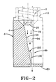
Fig. 2 is a cross-section taken fromFig. 1 along lines 2-2. - With reference to
Figs. 1 and2 , an extruder (partially shown) has anextruder screw 2 with an extruder screw tip 4 enclosed in anextruder barrel 3. Attached to the extruder barrel is anextruder head 5. The extruder head has aflow channel 10 for receiving plastic or elastomeric material such as rubber. Theflow channel 10 is further divided downstream into twoflow channels channel - After the material flows from the
extruder barrel 3 and enters the inlet of theflow channel 10, the mass flow is divided into twoflow channels angled flow channels inner walls 70 than along theoutside walls 72. Further, more of the mass of the material is concentrated along theinner wall 70. Thus the angled flow channel results in an uneven mass and velocity distribution, with a faster flowing mass more concentrated along the inner wall. - To counteract this flow imbalance, a
transition section 80 is added prior to theflow discharge section 90. Thetransition section 80 comprises inner and outerflat sidewalls transition section 80 has a length L and a width W. Preferably the width about equals the length, and has a sufficient length L sized to stabilize the flow into a uniform mass profile. Thus the flow in the transition area is parallel to the inlet flow and the discharge flow. The width W is the distance between theinner sidewall 82 and theouter sidewall 84. - Since a disproportionate amount of mass of the material entering the transition area is near the
inner wall 82, thetransition area 80 functions to shift the mass towards theouter wall 84, so that the center of mass of the flow is centered in alignment with the downstream flow divertor. Thetransition section 80 has a centerline which is slightly offset towards the outer wall from the centerline of the flow discharge channel. The effect of the offset transition centerline is to shift the mass of the flow towards the outer wall, and thus into a more uniform distribution. The amount of centerline transition offset may depend upon the flow characteristics of the particular material selected. Typically for rubber, the offset may be in the range of 1 to 6 mm. - After the flow exits the transition area, it enters the
flow discharge channel 90. Centered with each flow discharge channel is aflow divertor 100, which is preferably shaped like a wing, having sweeping leadingedges 102. Each flow divertor is preferably symmetrical in design about its centerline. Theflow divertor 100 functions to spread out the material into the desired width prior to flowing into thedie 60.
Claims (9)
- An extruder head comprising a flow inlet (10) for receiving a material to be extruded; and a first and a second flow channel (40, 50) communicating with an end of the flow inlet (10); wherein each flow channel (40, 50) has a transition section (80) having sidewalls (82, 84) and a centerline; wherein a first flow discharge section (90) is in fluid communication with the first flow channel (40) and a second flow discharge section (90) is in fluid communication with the second flow channel (50); and wherein each flow discharge section (90) has a divertor (100) centered therein, the divertor having a centerline; characterized in that the centerline of the transition section (80) is offset from the centerline of the divertor (100).
- The extruder head of claim 1, wherein the sidewalls (82, 84) of the transition section (80) are flat and/or wherein the sidewalls (82, 84) where entering and exiting the transition section (80) are curved.
- The extruder head of claim 1 or 2, wherein the transition section (80) has a length (L) which is sufficient to stabilize the flow of the material to be extruded into a uniform mass profile.
- The extruder head of at least one of the previous claims, wherein the transition section (80) has a length (L) and a width, the width being 90% to 140 %, preferably 95% to 120%, of the length (L).
- The extruder head of at least one of the previous claims, wherein the flow of the material in the transition section (80) is parallel to the flow of the material in the flow inlet (10) and is parallel to the flow of the material at the exit of the divertor (100).
- The extruder head of at least one of the previous claims, wherein the centerline of the transition section (80) is offset towards the outer sidewall (84) from the centerline of the divertor (100).
- The extruder head of at least one of the previous claims, wherein the offset is in the range of 1 mm to 6 mm.
- The extruder head of at least one of the previous claims, wherein the divertor (100) is shaped like a wing having sweaping leading edges (102).
- A method of forming simultaneously two or more elastomeric strips of predetermined cross-sectional profiles from a material, the method comprising the steps of:(a) receiving the material from an extruder into a channel (10);(b) dividing the material from the channel (10) into a first and a second angled flow channel (40, 50),(c) straightening out the flow of the material in a transition section (80) of the first and second flow channel (40, 50);(d) aligning the center of mass of the material with the center of a divertor (100) located in a discharge section (90) by offsetting the centerline of the transition section (80) from the centerline of the divertor (100); and(e) discharging the material from the discharge section (90) into a die (60) and/or a preformer.
Applications Claiming Priority (1)
| Application Number | Priority Date | Filing Date | Title |
|---|---|---|---|
| US10/964,010 US20060076703A1 (en) | 2004-10-13 | 2004-10-13 | Double flow channel for an extruder head |
Publications (3)
| Publication Number | Publication Date |
|---|---|
| EP1647390A2 EP1647390A2 (en) | 2006-04-19 |
| EP1647390A3 EP1647390A3 (en) | 2006-11-15 |
| EP1647390B1 true EP1647390B1 (en) | 2008-10-08 |
Family
ID=35695620
Family Applications (1)
| Application Number | Title | Priority Date | Filing Date |
|---|---|---|---|
| EP05109338A Expired - Fee Related EP1647390B1 (en) | 2004-10-13 | 2005-10-07 | Double flow channel for an extruder head |
Country Status (7)
| Country | Link |
|---|---|
| US (1) | US20060076703A1 (en) |
| EP (1) | EP1647390B1 (en) |
| JP (1) | JP4786288B2 (en) |
| CN (1) | CN1760012A (en) |
| BR (1) | BRPI0504300A (en) |
| DE (1) | DE602005010177D1 (en) |
| ES (1) | ES2317155T3 (en) |
Families Citing this family (8)
| Publication number | Priority date | Publication date | Assignee | Title |
|---|---|---|---|---|
| JP4426937B2 (en) * | 2004-09-14 | 2010-03-03 | 住友ゴム工業株式会社 | Rubber strip manufacturing equipment |
| US8308470B2 (en) * | 2005-11-04 | 2012-11-13 | University Of Southern California | Extrusion of cementitious material with different curing rates |
| US7754124B2 (en) * | 2006-04-21 | 2010-07-13 | Southwire Company | Method and apparatus for multi-stream metered extrusion |
| DE102007030369B4 (en) * | 2007-06-29 | 2015-08-27 | Harald Feuerherm | Process for producing blow-molded hollow bodies |
| JP5820197B2 (en) * | 2011-08-31 | 2015-11-24 | 積水化学工業株式会社 | Mold for extrusion of wide plate resin |
| US20130154142A1 (en) * | 2011-12-19 | 2013-06-20 | Warren Paul Ripple | Conicity correction for rubber component extrusion |
| CN105216271A (en) * | 2015-10-16 | 2016-01-06 | 苏州杰威尔精密机械有限公司 | One goes out multi-mode structure |
| DE102019208750A1 (en) * | 2019-06-17 | 2020-12-17 | Continental Reifen Deutschland Gmbh | Method for producing a pneumatic vehicle tire, device for forming a rubber profile comprising two wing components and a discharge component and use of the device as well as pneumatic vehicle tires |
Family Cites Families (33)
| Publication number | Priority date | Publication date | Assignee | Title |
|---|---|---|---|---|
| FR2087753A5 (en) * | 1970-05-29 | 1971-12-31 | Saint Gobain | |
| US3901636A (en) * | 1973-06-11 | 1975-08-26 | Beloit Corp | Plastic extrusion and odor elimination apparatus |
| US4032279A (en) * | 1975-09-08 | 1977-06-28 | The B. F. Goodrich Company | Extrusion adapter |
| US4076477A (en) * | 1975-12-08 | 1978-02-28 | Grandview Industries Limited | Multiple extrusion apparatus |
| US4107246A (en) * | 1976-12-20 | 1978-08-15 | Phillips Petroleum Company | Extrusion control |
| US4081231A (en) * | 1976-12-23 | 1978-03-28 | Mobil Oil Corporation | Flow distribution valve for dual thermoplastic tube extrusion |
| US4316710A (en) * | 1980-03-24 | 1982-02-23 | The Goodyear Tire & Rubber Company | Duplex extruder head |
| IT1129467B (en) * | 1980-12-19 | 1986-06-04 | Lavorazione Mat Plast | ADAPTER FOR SIMULTANEOUS EXTRUSION OF MULTIPLE THREADS OF SYNTHETIC THERMOPLASTIC FOAM USING A SINGLE EXTRUDER |
| US4439125A (en) * | 1982-03-31 | 1984-03-27 | The Firestone Tire & Rubber Company | Adjustable die mechanism |
| DE3238284C2 (en) * | 1982-10-15 | 1986-08-07 | Hermann Berstorff Maschinenbau Gmbh, 3000 Hannover | Extrusion head for the production of flat profiles from various rubber or plastic compounds |
| DE3506257C1 (en) * | 1985-02-22 | 1986-04-30 | Hermann Berstorff Maschinenbau Gmbh, 3000 Hannover | Hinged multiple extrusion head for the production of tread patterns for tire production |
| DE3521643C1 (en) * | 1985-06-15 | 1986-07-03 | Hermann Berstorff Maschinenbau Gmbh, 3000 Hannover | Hinged extrusion head for the production of rubber or plastic flat profiles |
| DE3534770C1 (en) * | 1985-09-30 | 1986-11-13 | Hermann Berstorff Maschinenbau Gmbh, 3000 Hannover | Method and arrangement for starting up a multiple extrusion press with little loss of material in order to produce profile sections made of different rubber or plastic mixtures, for example for treads or side strips of vehicle tires |
| DE3638623C1 (en) * | 1986-11-12 | 1987-10-22 | Berstorff Gmbh Masch Hermann | Extrusion head for the production of treads for car tires consisting of various rubber compounds |
| US4990293A (en) * | 1987-11-09 | 1991-02-05 | Regents Of The University Of Minnesota | Process of and apparatus for extruding a reactive polymer mixture |
| US4945807A (en) * | 1988-08-29 | 1990-08-07 | Apv Chemical Machinery, Inc. | Method and apparatus for processing potentially explosive and sensitive materials for forming longitudinally perforated extrudate strands |
| US5017118A (en) * | 1989-06-16 | 1991-05-21 | The Goodyear Tire & Rubber Company | Apparatus for forming a coextrusion from extruded strips |
| US5980226A (en) * | 1993-11-05 | 1999-11-09 | Guillemette; A. Roger | Modular die assembly |
| US5667818A (en) * | 1993-11-05 | 1997-09-16 | Guillemette; A. Roger | Extrusion system with balanced flow passage |
| US5527499A (en) * | 1995-01-31 | 1996-06-18 | Bridgestone/Firestone, Inc. | Extrusion apparatus and method with pressure equalization |
| US5616350A (en) * | 1995-04-10 | 1997-04-01 | Cincinnati Milacron Inc. | Dual flow divider with diverter valve |
| DE19517246A1 (en) * | 1995-05-15 | 1996-11-21 | Troester Maschf Paul | Spray head for an extrusion plant in the rubber or plastics processing industry |
| US5836680A (en) * | 1996-03-26 | 1998-11-17 | The Goodyear Tire & Rubber Company | Extruder with feedback loop control |
| IT1290520B1 (en) * | 1997-04-03 | 1998-12-04 | Pirelli | EXTRUSION METHOD AND APPARATUS FOR MAKING TREAD BANDS FOR VEHICLE TIRES |
| EP1034070B1 (en) * | 1997-10-31 | 2005-08-17 | The Goodyear Tire & Rubber Company | Universal flow channel |
| US6340123B1 (en) * | 1997-10-31 | 2002-01-22 | Ching-Chin Lee | Universal flow channel |
| US6409491B1 (en) * | 1998-04-23 | 2002-06-25 | E. I. Du Pont De Nemours And Company | Extrusion die assembly |
| US6945764B2 (en) * | 2000-04-10 | 2005-09-20 | Guillemette A Roger | Method and apparatus for distributing material in a profile extrusion die |
| US6478564B1 (en) * | 2000-09-08 | 2002-11-12 | The Goodyear Tire & Rubber Company | Adjustable flow channel for an extruder head |
| US6491510B1 (en) * | 2000-09-08 | 2002-12-10 | The Goodyear Tire & Rubber Company | Adjustable flow channel for an extruder head |
| US6746227B2 (en) * | 2001-06-19 | 2004-06-08 | The Goodyear Tire & Rubber Company | Tire tread die |
| US20040185132A1 (en) * | 2003-03-19 | 2004-09-23 | The Goodyear Tire & Rubber Company | Removable flow diverter for an extrusion head |
| JP4426937B2 (en) * | 2004-09-14 | 2010-03-03 | 住友ゴム工業株式会社 | Rubber strip manufacturing equipment |
-
2004
- 2004-10-13 US US10/964,010 patent/US20060076703A1/en not_active Abandoned
-
2005
- 2005-10-04 BR BRPI0504300-0A patent/BRPI0504300A/en not_active Application Discontinuation
- 2005-10-07 ES ES05109338T patent/ES2317155T3/en active Active
- 2005-10-07 DE DE602005010177T patent/DE602005010177D1/en active Active
- 2005-10-07 EP EP05109338A patent/EP1647390B1/en not_active Expired - Fee Related
- 2005-10-12 JP JP2005297053A patent/JP4786288B2/en not_active Expired - Fee Related
- 2005-10-13 CN CNA2005101135774A patent/CN1760012A/en active Pending
Also Published As
| Publication number | Publication date |
|---|---|
| CN1760012A (en) | 2006-04-19 |
| JP4786288B2 (en) | 2011-10-05 |
| ES2317155T3 (en) | 2009-04-16 |
| BRPI0504300A (en) | 2006-05-23 |
| EP1647390A3 (en) | 2006-11-15 |
| US20060076703A1 (en) | 2006-04-13 |
| EP1647390A2 (en) | 2006-04-19 |
| DE602005010177D1 (en) | 2008-11-20 |
| JP2006111014A (en) | 2006-04-27 |
Similar Documents
| Publication | Publication Date | Title |
|---|---|---|
| EP1647390B1 (en) | Double flow channel for an extruder head | |
| CA1243167A (en) | Apparatus for forming a co-extrusion from extruded strips | |
| US6495081B2 (en) | Method for manufacturing tread bands for vehicle tires | |
| US7494335B2 (en) | Apparatus for producing rubber strip | |
| JP4589581B2 (en) | Adjustable flow path for extruder head | |
| JP5039127B2 (en) | Unvulcanized rubber extrusion apparatus and method for producing unvulcanized rubber | |
| EP1186396B1 (en) | Adjustable flow channel for an extruder head | |
| EP2682249B1 (en) | Method and system for a rubber component extrusion | |
| EP1491318B1 (en) | Roller die preformer for wide extrusions and method of extruding | |
| US6776946B2 (en) | Method and apparatus for rubber extruding | |
| JP4500073B2 (en) | Extruder head and manufacturing method thereof | |
| US5411692A (en) | Integral reclosable bag die assembly | |
| EP1240994B1 (en) | Apparatus and method for extruding unvulcanized rubber | |
| US20080271671A1 (en) | Extrusion Nozzle for Extruding Hollow Profiles | |
| RU2574248C2 (en) | Extrusion process and device for production of elastomer compounds |
Legal Events
| Date | Code | Title | Description |
|---|---|---|---|
| PUAI | Public reference made under article 153(3) epc to a published international application that has entered the european phase |
Free format text: ORIGINAL CODE: 0009012 |
|
| AK | Designated contracting states |
Kind code of ref document: A2 Designated state(s): AT BE BG CH CY CZ DE DK EE ES FI FR GB GR HU IE IS IT LI LT LU LV MC NL PL PT RO SE SI SK TR |
|
| AX | Request for extension of the european patent |
Extension state: AL BA HR MK YU |
|
| PUAL | Search report despatched |
Free format text: ORIGINAL CODE: 0009013 |
|
| AK | Designated contracting states |
Kind code of ref document: A3 Designated state(s): AT BE BG CH CY CZ DE DK EE ES FI FR GB GR HU IE IS IT LI LT LU LV MC NL PL PT RO SE SI SK TR |
|
| AX | Request for extension of the european patent |
Extension state: AL BA HR MK YU |
|
| 17P | Request for examination filed |
Effective date: 20070515 |
|
| 17Q | First examination report despatched |
Effective date: 20070615 |
|
| AKX | Designation fees paid |
Designated state(s): DE ES FR |
|
| GRAP | Despatch of communication of intention to grant a patent |
Free format text: ORIGINAL CODE: EPIDOSNIGR1 |
|
| GRAS | Grant fee paid |
Free format text: ORIGINAL CODE: EPIDOSNIGR3 |
|
| GRAA | (expected) grant |
Free format text: ORIGINAL CODE: 0009210 |
|
| AK | Designated contracting states |
Kind code of ref document: B1 Designated state(s): DE ES FR |
|
| REF | Corresponds to: |
Ref document number: 602005010177 Country of ref document: DE Date of ref document: 20081120 Kind code of ref document: P |
|
| REG | Reference to a national code |
Ref country code: ES Ref legal event code: FG2A Ref document number: 2317155 Country of ref document: ES Kind code of ref document: T3 |
|
| PLBE | No opposition filed within time limit |
Free format text: ORIGINAL CODE: 0009261 |
|
| STAA | Information on the status of an ep patent application or granted ep patent |
Free format text: STATUS: NO OPPOSITION FILED WITHIN TIME LIMIT |
|
| 26N | No opposition filed |
Effective date: 20090709 |
|
| REG | Reference to a national code |
Ref country code: ES Ref legal event code: FD2A Effective date: 20110307 |
|
| PG25 | Lapsed in a contracting state [announced via postgrant information from national office to epo] |
Ref country code: ES Free format text: LAPSE BECAUSE OF NON-PAYMENT OF DUE FEES Effective date: 20110304 |
|
| PG25 | Lapsed in a contracting state [announced via postgrant information from national office to epo] |
Ref country code: ES Free format text: LAPSE BECAUSE OF NON-PAYMENT OF DUE FEES Effective date: 20091008 |
|
| REG | Reference to a national code |
Ref country code: FR Ref legal event code: PLFP Year of fee payment: 12 |
|
| REG | Reference to a national code |
Ref country code: FR Ref legal event code: PLFP Year of fee payment: 13 |
|
| PGFP | Annual fee paid to national office [announced via postgrant information from national office to epo] |
Ref country code: DE Payment date: 20171027 Year of fee payment: 13 |
|
| REG | Reference to a national code |
Ref country code: FR Ref legal event code: PLFP Year of fee payment: 14 |
|
| REG | Reference to a national code |
Ref country code: DE Ref legal event code: R079 Ref document number: 602005010177 Country of ref document: DE Free format text: PREVIOUS MAIN CLASS: B29C0047300000 Ipc: B29C0048345000 |
|
| REG | Reference to a national code |
Ref country code: DE Ref legal event code: R119 Ref document number: 602005010177 Country of ref document: DE |
|
| PG25 | Lapsed in a contracting state [announced via postgrant information from national office to epo] |
Ref country code: DE Free format text: LAPSE BECAUSE OF NON-PAYMENT OF DUE FEES Effective date: 20190501 |
|
| PGFP | Annual fee paid to national office [announced via postgrant information from national office to epo] |
Ref country code: FR Payment date: 20200914 Year of fee payment: 16 |
|
| PG25 | Lapsed in a contracting state [announced via postgrant information from national office to epo] |
Ref country code: FR Free format text: LAPSE BECAUSE OF NON-PAYMENT OF DUE FEES Effective date: 20211031 |