EP1647293A1 - Sicherheitsspritze mit Ruckziehmechanismus - Google Patents
Sicherheitsspritze mit Ruckziehmechanismus Download PDFInfo
- Publication number
- EP1647293A1 EP1647293A1 EP04255693A EP04255693A EP1647293A1 EP 1647293 A1 EP1647293 A1 EP 1647293A1 EP 04255693 A EP04255693 A EP 04255693A EP 04255693 A EP04255693 A EP 04255693A EP 1647293 A1 EP1647293 A1 EP 1647293A1
- Authority
- EP
- European Patent Office
- Prior art keywords
- connector
- seating
- plunger
- barrel
- flange
- Prior art date
- Legal status (The legal status is an assumption and is not a legal conclusion. Google has not performed a legal analysis and makes no representation as to the accuracy of the status listed.)
- Withdrawn
Links
- 230000002093 peripheral effect Effects 0.000 claims description 5
- 239000012530 fluid Substances 0.000 claims description 3
- 230000000284 resting effect Effects 0.000 claims 1
- 238000002347 injection Methods 0.000 description 6
- 239000007924 injection Substances 0.000 description 6
- 239000003814 drug Substances 0.000 description 4
- 239000007788 liquid Substances 0.000 description 4
- 230000000694 effects Effects 0.000 description 2
- 230000004048 modification Effects 0.000 description 2
- 238000012986 modification Methods 0.000 description 2
- 208000012266 Needlestick injury Diseases 0.000 description 1
- 201000010099 disease Diseases 0.000 description 1
- 208000037265 diseases, disorders, signs and symptoms Diseases 0.000 description 1
- 210000003811 finger Anatomy 0.000 description 1
- 208000015181 infectious disease Diseases 0.000 description 1
- 230000001681 protective effect Effects 0.000 description 1
- 210000003813 thumb Anatomy 0.000 description 1
Images





Classifications
-
- A—HUMAN NECESSITIES
- A61—MEDICAL OR VETERINARY SCIENCE; HYGIENE
- A61M—DEVICES FOR INTRODUCING MEDIA INTO, OR ONTO, THE BODY; DEVICES FOR TRANSDUCING BODY MEDIA OR FOR TAKING MEDIA FROM THE BODY; DEVICES FOR PRODUCING OR ENDING SLEEP OR STUPOR
- A61M5/00—Devices for bringing media into the body in a subcutaneous, intra-vascular or intramuscular way; Accessories therefor, e.g. filling or cleaning devices, arm-rests
- A61M5/178—Syringes
- A61M5/31—Details
- A61M5/32—Needles; Details of needles pertaining to their connection with syringe or hub; Accessories for bringing the needle into, or holding the needle on, the body; Devices for protection of needles
- A61M5/3205—Apparatus for removing or disposing of used needles or syringes, e.g. containers; Means for protection against accidental injuries from used needles
- A61M5/321—Means for protection against accidental injuries by used needles
- A61M5/322—Retractable needles, i.e. disconnected from and withdrawn into the syringe barrel by the piston
-
- A—HUMAN NECESSITIES
- A61—MEDICAL OR VETERINARY SCIENCE; HYGIENE
- A61M—DEVICES FOR INTRODUCING MEDIA INTO, OR ONTO, THE BODY; DEVICES FOR TRANSDUCING BODY MEDIA OR FOR TAKING MEDIA FROM THE BODY; DEVICES FOR PRODUCING OR ENDING SLEEP OR STUPOR
- A61M5/00—Devices for bringing media into the body in a subcutaneous, intra-vascular or intramuscular way; Accessories therefor, e.g. filling or cleaning devices, arm-rests
- A61M5/178—Syringes
- A61M5/31—Details
- A61M5/32—Needles; Details of needles pertaining to their connection with syringe or hub; Accessories for bringing the needle into, or holding the needle on, the body; Devices for protection of needles
- A61M5/34—Constructions for connecting the needle, e.g. to syringe nozzle or needle hub
- A61M5/347—Constructions for connecting the needle, e.g. to syringe nozzle or needle hub rotatable, e.g. bayonet or screw
Definitions
- the present invention relates to a safety syringe, and more particularly to a safety syringe having a retraction mechanism that can be withdrawn back to an inside barrel directly for needle stick protection after syringe operation, without any additional operation to motivate the retraction mechanism.
- a conventional syringe comprises a barrel, a needle firmly seated on an end-portion of the barrel with a tapped adapter, and a plunger inserted into the barrel.
- the plunger When starting to operate the syringe, the plunger is pulled backward to draw the liquid medicine into the barrel. Then, the plunger can be pushed forward to inject the liquid medicine through the needle hole into the human body.
- the needle is protruded outward from the barrel, so that the operator or other medical personnel is easily hurt by the protruding needle during syringe operation.
- U.S. Patent No. 6,066,115 Another conventional syringe was disclosed in U.S. Patent No. 6,066,115, comprising a barrel, a needle set mounted in the barrel and having a bottom provided with a barb-shaped elastic plate, and a plunger having an end-portion formed with a protruding post having a conical head.
- the primary objective of the present invention is to provide a safety syringe having a retraction mechanism that can be pulled directly to retract the needle back to an inside barrel without any additional operation to motivate the retraction mechanism.
- Another objective of the present invention is to provide a safety syringe, wherein the needle is withdrawn into the inside barrel after syringe operation, thereby preventing the operator or another medical personnel from being hurt by the protruding needle, so as to provide a protective effect when syringe operation.
- a further objective of the present invention is to provide a safety syringe that can be manufactured easily in automatic equipment, thereby facilitating the user using the safety syringe.
- a further objective of the present invention is to provide a single use and disposable safety syringe, so that the patient can be reduced the possibility of infection by other diseases.
- a safety syringe comprising:
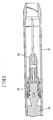
- a safety syringe in accordance with the preferred embodiment of the present invention comprises a barrel 10, a connector 20 seated in the barrel 10, and a plunger 30 inserted to the inside barrel. And on the distal end of the plunger 30 there are two features of withdraw-ring 34 and stop-column 35 are formed to ensure the connector 20 to be pulled back and stored into the barrel inside when the plunger 30 is withdrawn.
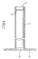
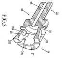
- the inside of the barrel 10 on an end 12 is formed to a seating-ring 14 which is protruded from one end 12 of the inside barrel for receiving a seating-flanges 282 of the connector 20.
- a seating-ring 14 which is protruded from one end 12 of the inside barrel for receiving a seating-flanges 282 of the connector 20.
- an enlarged thumb rest 18 for fingers easily holding when syringe operation.
- a connector 20 on an end-portion is formed to a protruding tube 22 with a fluid path in the central tube 26.
- Another end-portion is formed to an tube-shaped body 24.
- Surrounding the peripheral wall of the tube-shaped body 24 is arranged a plurality of resilient leverage plates 28 with the seating-flanges 282 and the releasing-flange 284 protruded on each end, a plurality of fixing plates 27, and a plurality of mediate portion formed to a connecting rib 281 to connect a respective fixing plate 27 and resilient leverage plates 28.
- a gap 25 is formed between the protruding tube 22 and the tube-shaped body 24 for receiving the withdraw-ring 34 of plunger 30.
- the connector 20 with the part of seating-flange 282 to seat on the seating-ring 14 and with the another part of ring-seal 32 fitting in the lumen of barrel 10 to provide a waterproof effect and maintain the connector 20 in a fixed position.
- the plunger 30 draws the liquid medicine into the barrel 10 and is pushed forward continuously for injection, the distal end of the plunger 30 is moved into the tube-shaped body 24 of the connector 20.
- the distal end of the plunger 30 is continuously moved in the tube-shaped body 24 of the connector 20.
- the withdraw-ring 34 of the plunger 30 starts pressing the releasing-flange 284 of the connector 20 upward to make the seating-flange 282 of the connector 20 releasing the seating relation gradually between the seating-flange 282 of the connector 20 and the seating-ring 14 of the barrel 10.
- the releasing-flange 284 of the connector 20 will climb over the withdraw-ring 34 of the plunger 30 and resides on the stop-column 35 of the plunger 30. Then, the withdraw-ring 34 is dropped into the gap 25 of the connector 20 to engage with the connector 20 together.
- the stop-column 35 is adjacent to the withdraw-ring 34 and which is formed to an accommodate diameter to ensure the seating-flange 282 of the connector 20 completely releasing from the seating-ring 14 of the barrel 10.
- Fig. 8 is a partially perspective cross-sectional view of a connector of a safety syringe in accordance with another embodiment of the present invention.
- One end-portion of the connector 20 is formed to a protruding tube 22 with a core hole 26 for receiving a size of cannula.
- Another end-portion is formed to a tube-shaped body 24.
- Surrounding the peripheral wall of the tube-shaped body 24 is arranged a plurality of resilient leverage plates 28 with seating-flanges 282 and releasing-flange 284 which are protruded on each end, a plurality of fixing plates 27.
- a plurality of mediate portions are formed to a connecting rib 281 to connect a respective fixing plate 27 and resilient leverage plates 28.
- in the middle of the connector 20 having a gap 25 are formed between the protruding tube 22 and the tube-shaped body 24 for receiving the withdraw-ring 34 of the plunger 30.
- a size of cannula 500 is mounted on the core hole 26 of the protruding tube 22 in the connector 20.
- the connector 20 with the part of the seating-flange 282 to seat on the seating-ring 14 and with another part of the ring-seal 32 fitting in the lumen of barrel 10 to provide a waterproof effect and maintain the connector 20 in a fixed position.
- the plunger 30 draws the liquid medicine into the barrel 10 and is pushed forward continuously for injection, the distal end of the plunger 30 is moved into the tube-shaped body 24 of the connector 20.
- the distal end of the plunger 30 is continuously moved in the tube-shaped body 24 of the connector 20.
- the withdraw-ring 34 of the plunger 30 starts pressing the releasing-flange 284 of the connector 20 upward to make the seating-flange 282 of the connector 20 releasing the seating relation gradually between the seating-flange 282 of the connector 20 and the seating-ring 14 of the barrel 10.
- the releasing-flange 284 of the connector 20 will climb over the withdraw-ring 34 of the plunger 30 and resides on the stop-column 35 of the plunger 30. Then the withdraw-ring 34 is dropped into the gap 25 of the connector 20 to engage with the connector 20 together.
- the stop-column 35 is adjacent to the withdraw-ring 34 and which is formed to an accommodate diameter to ensure the seating-flange 282 of the connector 20 completely releasing from the seating-ring 14 of the barrel 10.
Landscapes
- Health & Medical Sciences (AREA)
- Engineering & Computer Science (AREA)
- Heart & Thoracic Surgery (AREA)
- Vascular Medicine (AREA)
- Anesthesiology (AREA)
- Biomedical Technology (AREA)
- Environmental & Geological Engineering (AREA)
- Hematology (AREA)
- Life Sciences & Earth Sciences (AREA)
- Animal Behavior & Ethology (AREA)
- General Health & Medical Sciences (AREA)
- Public Health (AREA)
- Veterinary Medicine (AREA)
- Infusion, Injection, And Reservoir Apparatuses (AREA)
Priority Applications (1)
| Application Number | Priority Date | Filing Date | Title |
|---|---|---|---|
| EP04255693A EP1647293A1 (de) | 2004-09-18 | 2004-09-18 | Sicherheitsspritze mit Ruckziehmechanismus |
Applications Claiming Priority (1)
| Application Number | Priority Date | Filing Date | Title |
|---|---|---|---|
| EP04255693A EP1647293A1 (de) | 2004-09-18 | 2004-09-18 | Sicherheitsspritze mit Ruckziehmechanismus |
Publications (1)
| Publication Number | Publication Date |
|---|---|
| EP1647293A1 true EP1647293A1 (de) | 2006-04-19 |
Family
ID=34930668
Family Applications (1)
| Application Number | Title | Priority Date | Filing Date |
|---|---|---|---|
| EP04255693A Withdrawn EP1647293A1 (de) | 2004-09-18 | 2004-09-18 | Sicherheitsspritze mit Ruckziehmechanismus |
Country Status (1)
| Country | Link |
|---|---|
| EP (1) | EP1647293A1 (de) |
Cited By (2)
| Publication number | Priority date | Publication date | Assignee | Title |
|---|---|---|---|---|
| EA010544B1 (ru) * | 2006-12-25 | 2008-10-30 | Хунг-Чи Хуанг | Безопасный шприц |
| JP2013099512A (ja) * | 2011-11-07 | 2013-05-23 | Juo-Ying Chen | 注射器 |
Citations (6)
| Publication number | Priority date | Publication date | Assignee | Title |
|---|---|---|---|---|
| WO1989004681A1 (en) * | 1987-11-18 | 1989-06-01 | Catch 522 Pty. Limited | Single use syringe |
| WO1993006880A1 (en) * | 1991-10-04 | 1993-04-15 | Retrax, Inc. | Retractable syringe |
| US5324265A (en) * | 1993-10-20 | 1994-06-28 | Gabbard Murray Gabbard Inc. | Hypodermic safety syringe with retracting needle system |
| US6193695B1 (en) * | 2000-01-14 | 2001-02-27 | Wayland J. Rippstein, Jr. | Disposable safety syringe having a retractable needle |
| US6599270B1 (en) * | 2002-10-29 | 2003-07-29 | Cho Ying Chen | Syringe with a snapping device for backward pulling the needle into the syringe after syringing |
| US6706019B1 (en) * | 1998-09-25 | 2004-03-16 | David W. Parker | Hypodermic syringes |
-
2004
- 2004-09-18 EP EP04255693A patent/EP1647293A1/de not_active Withdrawn
Patent Citations (6)
| Publication number | Priority date | Publication date | Assignee | Title |
|---|---|---|---|---|
| WO1989004681A1 (en) * | 1987-11-18 | 1989-06-01 | Catch 522 Pty. Limited | Single use syringe |
| WO1993006880A1 (en) * | 1991-10-04 | 1993-04-15 | Retrax, Inc. | Retractable syringe |
| US5324265A (en) * | 1993-10-20 | 1994-06-28 | Gabbard Murray Gabbard Inc. | Hypodermic safety syringe with retracting needle system |
| US6706019B1 (en) * | 1998-09-25 | 2004-03-16 | David W. Parker | Hypodermic syringes |
| US6193695B1 (en) * | 2000-01-14 | 2001-02-27 | Wayland J. Rippstein, Jr. | Disposable safety syringe having a retractable needle |
| US6599270B1 (en) * | 2002-10-29 | 2003-07-29 | Cho Ying Chen | Syringe with a snapping device for backward pulling the needle into the syringe after syringing |
Cited By (2)
| Publication number | Priority date | Publication date | Assignee | Title |
|---|---|---|---|---|
| EA010544B1 (ru) * | 2006-12-25 | 2008-10-30 | Хунг-Чи Хуанг | Безопасный шприц |
| JP2013099512A (ja) * | 2011-11-07 | 2013-05-23 | Juo-Ying Chen | 注射器 |
Similar Documents
| Publication | Publication Date | Title |
|---|---|---|
| US4927414A (en) | Syringe with safety retracting needle | |
| CN107715256B (zh) | 手掌激活型药物递送装置 | |
| US7407493B2 (en) | Container for disposable needle or cannula | |
| CN110215571B (zh) | 手掌激活型药物递送装置 | |
| US5211628A (en) | Syringe with automatic retracting needle | |
| US12121708B2 (en) | Safety housing based implant/medicament injecting system | |
| EP2561812A1 (de) | In einem automatisierten und schmerzlosen verfahren eingesetzte einweg-sicherheitslanzettenvorrichtung | |
| JP2012526607A (ja) | Ivカテーテル導入器 | |
| JP2002516158A (ja) | 自己引込型カテーテルイントロデューサ | |
| JP2010188176A (ja) | プレフィルド注射器用の安全シールドシステム | |
| KR20150065733A (ko) | 신속 해제 플런저 | |
| NO334598B1 (no) | Instrument med tilbaketrekkbar nål for intravenøs kateter-innføring, samt fremgangsmåte til montering av samme. | |
| JPH11503358A (ja) | 医療用注射器と自動回収注射針装置 | |
| HU226405B1 (en) | Automatically operable safety shield system for syringes | |
| JPH10127767A (ja) | 片手操作可能な針バリアーを備えた針アセンブリ | |
| US20060069354A1 (en) | Syringe activation device | |
| WO2015160600A1 (en) | Medication delivery device | |
| US20060264887A1 (en) | Syringe sheath | |
| JP2016506282A (ja) | 安全な静脈留置針 | |
| EP1159983A1 (de) | Klemme für Nadel mit Flügeln | |
| US20060106341A1 (en) | Safety syringe having retraction mechanism | |
| EP1647293A1 (de) | Sicherheitsspritze mit Ruckziehmechanismus | |
| JP3208190U (ja) | 安全注射筒 | |
| CN112672782B (zh) | 防止重复使用的安全导管 | |
| JPH05503649A (ja) | 引き込み可能な針を有する注射器 |
Legal Events
| Date | Code | Title | Description |
|---|---|---|---|
| PUAI | Public reference made under article 153(3) epc to a published international application that has entered the european phase |
Free format text: ORIGINAL CODE: 0009012 |
|
| 17P | Request for examination filed |
Effective date: 20050708 |
|
| AK | Designated contracting states |
Kind code of ref document: A1 Designated state(s): AT BE BG CH CY CZ DE DK EE ES FI FR GB GR HU IE IT LI LU MC NL PL PT RO SE SI SK TR |
|
| AX | Request for extension of the european patent |
Extension state: AL HR LT LV MK |
|
| GRAP | Despatch of communication of intention to grant a patent |
Free format text: ORIGINAL CODE: EPIDOSNIGR1 |
|
| AKX | Designation fees paid |
Designated state(s): AT BE BG CH CY CZ DE DK EE ES FI FR GB GR HU IE IT LI LU MC NL PL PT RO SE SI SK TR |
|
| STAA | Information on the status of an ep patent application or granted ep patent |
Free format text: STATUS: THE APPLICATION IS DEEMED TO BE WITHDRAWN |
|
| 18D | Application deemed to be withdrawn |
Effective date: 20070216 |