EP1647081B1 - Motor with modular stator segments - Google Patents
Motor with modular stator segments Download PDFInfo
- Publication number
- EP1647081B1 EP1647081B1 EP04744558A EP04744558A EP1647081B1 EP 1647081 B1 EP1647081 B1 EP 1647081B1 EP 04744558 A EP04744558 A EP 04744558A EP 04744558 A EP04744558 A EP 04744558A EP 1647081 B1 EP1647081 B1 EP 1647081B1
- Authority
- EP
- European Patent Office
- Prior art keywords
- stator
- motor
- segments
- segment
- rotor
- Prior art date
- Legal status (The legal status is an assumption and is not a legal conclusion. Google has not performed a legal analysis and makes no representation as to the accuracy of the status listed.)
- Expired - Lifetime
Links
- 238000004804 winding Methods 0.000 claims description 52
- 238000003475 lamination Methods 0.000 claims description 10
- 230000004907 flux Effects 0.000 claims description 8
- 239000000463 material Substances 0.000 claims description 6
- 239000004020 conductor Substances 0.000 claims 1
- 230000002093 peripheral effect Effects 0.000 claims 1
- 238000004519 manufacturing process Methods 0.000 description 5
- 238000005266 casting Methods 0.000 description 3
- RYGMFSIKBFXOCR-UHFFFAOYSA-N Copper Chemical compound [Cu] RYGMFSIKBFXOCR-UHFFFAOYSA-N 0.000 description 1
- 230000018199 S phase Effects 0.000 description 1
- 229910052802 copper Inorganic materials 0.000 description 1
- 239000010949 copper Substances 0.000 description 1
- 230000003247 decreasing effect Effects 0.000 description 1
- 238000009413 insulation Methods 0.000 description 1
- 239000000696 magnetic material Substances 0.000 description 1
- 230000007257 malfunction Effects 0.000 description 1
- 238000000034 method Methods 0.000 description 1
- 230000002265 prevention Effects 0.000 description 1
- 230000001012 protector Effects 0.000 description 1
- 238000003466 welding Methods 0.000 description 1
Images


Classifications
-
- H—ELECTRICITY
- H02—GENERATION; CONVERSION OR DISTRIBUTION OF ELECTRIC POWER
- H02K—DYNAMO-ELECTRIC MACHINES
- H02K1/00—Details of the magnetic circuit
- H02K1/06—Details of the magnetic circuit characterised by the shape, form or construction
- H02K1/22—Rotating parts of the magnetic circuit
- H02K1/27—Rotor cores with permanent magnets
- H02K1/2786—Outer rotors
- H02K1/2787—Outer rotors the magnetisation axis of the magnets being perpendicular to the rotor axis
- H02K1/2789—Outer rotors the magnetisation axis of the magnets being perpendicular to the rotor axis the rotor consisting of two or more circumferentially positioned magnets
- H02K1/2791—Surface mounted magnets; Inset magnets
-
- H—ELECTRICITY
- H02—GENERATION; CONVERSION OR DISTRIBUTION OF ELECTRIC POWER
- H02K—DYNAMO-ELECTRIC MACHINES
- H02K1/00—Details of the magnetic circuit
- H02K1/06—Details of the magnetic circuit characterised by the shape, form or construction
- H02K1/12—Stationary parts of the magnetic circuit
- H02K1/14—Stator cores with salient poles
- H02K1/146—Stator cores with salient poles consisting of a generally annular yoke with salient poles
- H02K1/148—Sectional cores
-
- H—ELECTRICITY
- H02—GENERATION; CONVERSION OR DISTRIBUTION OF ELECTRIC POWER
- H02K—DYNAMO-ELECTRIC MACHINES
- H02K1/00—Details of the magnetic circuit
- H02K1/06—Details of the magnetic circuit characterised by the shape, form or construction
- H02K1/22—Rotating parts of the magnetic circuit
- H02K1/28—Means for mounting or fastening rotating magnetic parts on to, or to, the rotor structures
- H02K1/30—Means for mounting or fastening rotating magnetic parts on to, or to, the rotor structures using intermediate parts, e.g. spiders
-
- H—ELECTRICITY
- H02—GENERATION; CONVERSION OR DISTRIBUTION OF ELECTRIC POWER
- H02K—DYNAMO-ELECTRIC MACHINES
- H02K7/00—Arrangements for handling mechanical energy structurally associated with dynamo-electric machines, e.g. structural association with mechanical driving motors or auxiliary dynamo-electric machines
- H02K7/14—Structural association with mechanical loads, e.g. with hand-held machine tools or fans
Definitions
- the invention is related to a motor, which comprises a stator with attachable and detachable pieces.
- the motors are designed to operate at a certain location where they provide the desired power, number of revolution etc., but when their location changes, producing a new motor with new parts, which are manufactured to meet the requirements of the new operating conditions is needed.
- direct driven motors used in household appliances particularly in washers/dryers, are designed respectively for each washer/dryer and can only be implemented to the washer/dryer that it's been designed for.
- the object of the invention is to provide a motor according to claim 1, which reaches the desired drive power by attaching and detaching many stator pieces which forms itself and which could be used in different appliances without the need of a special design.
- Figure 1 - is a schematic view of a washer/dryer.
- Figure 2 - is a perspective view of a tub on which a rotor and more than one stator group is placed.
- Figure 3 - is a perspective view of a tub on which two stator groups are placed.
- Figure 4 - is an exploded view of a motor comprising stator support on which a rotor, a sensor and more than one stator group is placed.
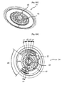
- Figure 5 - is an exploded view of a stator wheel on which an adaptor part and more than one stator group is placed.
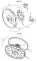
- Figure 6 - is an exploded rear view of a rotor group.
- Figure 7 - is a perspective front view of a stator support comprising more than one segment recesses.
- Figure 8 - is a perspective front view of one or more stator segments, comprising many fixing points at different positions, which are fixed in the fixing points that are at different positions and a stator support on which a sensor is fixed .
- Figure 9 - is a three dimensional front view of a stator segment.
- Figure 10 - is a three dimensional rear view of a stator segment.
- Figure 11 - is a three dimensional exploded view of a stator segment.
- Figure 12 - is a perspective side by side view of two stator segments which have connection surfaces with fitting shapes to each other.
- the motor (20), which is the subject of the invention, is used preferably in household appliances, particularly in washers /dryers comprising a drum (2) wherein laundry is put, a tub (3) wherein the drum (2) is placed and a shaft (4) which is connected with the drum or it is used in motor-driven bicycles.
- the motor (20) comprises a stator (30) which transforms the voltage it receives to a magnetic field, a rotor (70) which moves with the field formed by the stator (30), a sensor which is required to determine the condition and the position of the stator (30) and the rotor (70) and a control card (21) which enables controlling the stator (30) and the rotor (70) of the motor.
- the rotor (70) comprises even numbers of preferably two rotor segments (71) which has magnetic features for instance, lamination packet, which is made of magnetic materials or materials that could be magnetized, which is in a shape and/or number where it could form dipole, a rotor carrier (72) which is placed on rotor segments (71), a torque transmitter (73) which transmits torque to the parts to be rotated such as the drum (2) with the help of the driver of the rotor carrier (72), for example shaft (4), which is moved by the rotor segments (71).
- lamination packet which is made of magnetic materials or materials that could be magnetized, which is in a shape and/or number where it could form dipole
- a rotor carrier (72) which is placed on rotor segments (71)
- a torque transmitter (73) which transmits torque to the parts to be rotated such as the drum (2) with the help of the driver of the rotor carrier (72), for example shaft (4), which is moved by the rotor segments (71).
- the stator (30) comprises stator segments (31) having appropriate form to the rotor (70), fixed to other or used individually s at a required quantity and position according to the required motor (20) power, and or a stator support (34) which is fixed on stator segments (31) such as the tub (3).
- the rotor segment (7) is composed of one or more magnets
- the sensor(s) (22) are placed at an appropriate position and quantities in accordance to the rotor segments (71) and stator segments (31) quantity and position.
- the stator segment (31) comprises one or more stacks (32) which composes itself, one or more windings (33) which are made by wrapping of insulated wires over the stacks (32) with copper link, a case (35) made of insulated material, preferably made of plastic, which prevents the stack (32) from coming out of its place, which enables fastening to stator support (34) thus preventing electrical leakage, one or more segment fixing points (47) which is shaped like a recess and/or an extension that enables fastening, a stator outer surface (49) which is shaped like a spring that ensures the air gap between itself and the rotor (70) to remain fixed peripherally at all condition.
- Each of the stator segments (31), when they are required to be placed side by side with other stator segment, comprises a side contact surface (43) which enables side by side placement without leaving any gaps in between them in order to maintain continuity of flux and to prevent any loses, an input socket (40), which enables receiving the voltage that is transferred from the network voltage and/or from the previous stator segment (31), on the case (35) and which has a form appropriate to the required phase quantity, a conductive bridge (42) which carries the voltage from the input socket (40) to the other winding (33) which has the same phase in the stator segment (31), an output socket (41) which has a form appropriate to the phase quantity and which carries the voltage received from the network, the previous stator segment (31) or the bridge (42) to the next stator segment (31) and/or the network connection.
- Stator support (34) comprises one or more wheel fixing points (48) which have a shape of a recess and/or an extension that is appropriate to the segment fixing point (47), which ensures through its position and surface shape the distance (d2) between the middle axes of the windings (31) located at the point where the stator segments are placed adjacent to each other and the distance (d1) between the middle axes of the windings (33) to be equal, which ensures the distance (d3) between the stator segments (31) which are placed on itself that are not adjacent but next to each other and the distance (d1) between each middle axis of the winding (33) to be a whole number multiple, which establishes contact without leaving any gaps between the side contact surfaces in such a way that it prevents any loses in order to ensure the continuation of flux between the stator segments (31) which are placed adjacent to each other, which ensures the air gap between the stator segments (31) and the rotor (70) to remain fixed and which fastens the stator segments (31) and which prevents the stator segments
- Stator segments (31) are fastened on the stator support (34) in order to reach the maximum possible number of torque and revolution, in a circular form which encircles the rotor (70), in a way that it forms a full circular shape or in a circular shape formed by the rotor (70) that encircles it for lower number of torque and revolution, in a way that it partially forms a circular shape that provides the maximum force, in a position and quantity where the magnetic forces which are brought about when the voltage required is applied to reach the desired number of torques and revolution damaging the appliance on which they are placed on is prevented.
- the total number of the windings (33), which are on the stator segments (31) are fixed on the stator support (34), are a whole number multiple of the phase number required to be applied.
- the total number of windings (33), which are on the stator segments (31) are fixed adjacent to each other on the stator support (34) are also a whole number multiple of the phase number required to be applied and the distances (d1) between the whole middle axis of the winding (33) which are fixed adjacently on the stator segments (31) are equal.
- the stack (32) comprises more than one stator laminations (36) that form itself by overlapping each other.
- the stator segment (31) is composed of two stacks (32) which have winding (33) in between them and which are fastened to each other with tight fitting.
- more than one stator laminations (36) which form one of the stacks (32), comprises a pole extension (37) wherein one end is connected to other extension while the other end remains open and a locking form (39) located at the end which remains open.
- the stator segment (31) comprises a winding roller (38), which enables, preferably with the help of the pole extension (37), to fasten on the winding.
- the other stack (32) which forms the stator segment (31) is comprised of more than one lamination plates (36) which are connected to each other and which has a form appropriate to that of the case (35) which prevents the winding (33) from coming out of the pole extension (37) by having a form appropriate to the locking form (39).
- stacks are formed by placing the stator laminations (36) one after the other at a desired quantity, fixing them together preferably by welding and/or by driving in pins.
- winding (33) is formed by winding coil wire on winding roller (38) at a desired quantity.
- the coil wires on the winding are preferably coated with enameled material for insulation purposes.
- the winding roller (38) on the winding (33) is fixed on the pole extension (37), which is in the stack (32) and with the help of the locking form (39) both of the stacks (32) are rammed together.
- a case (35) is fixed on both ends and it is fastened on the stator support (34) with screws and the cable connections from the winding (33) are connected to each other, to the input socket (40) and the output socket (41).
- the edges of the contact surface (43) are formed by the side edges of the case (35) and the middle part is formed by the side surface of the stack (32).
- the stator segment (31) is used side by side with another stator segment (31)
- the contact surface of the two stator segments are in contact with each other.
- the stator segments' (31) windings (33), which are placed side by side, are connected to each other with the help of the input socket (40) and output socket (41) according to the required pole structure and the phase difference.
- the motor which is the subject of the invention, is designed both with a stator (30) comprised of one or more stator segments (31) which possess features, such as winding number, pole number, size etc., that provide the maximum number of torque and revolution that enables the household appliance to function and a rotor (70) which moves around the stator (30) and which is formed in a circular shape by the rotor segments (71) so that it encircles the circle formed by the stator (30) in a 360 degrees and it enables the household appliance (1) to operate at low power by placing stator segments (31), at a quantity less than the number of the stator segments (31) that could provide maximum power and equal to the required power, at appropriate quantities and positions in the same and/or different bodies without the need to make a different design even at powers lower than the maximum power.
- stator (30) comprised of one or more stator segments (31) which possess features, such as winding number, pole number, size etc., that provide the maximum number of torque and revolution that enables the household appliance to function
- the positions of the sensor (22), preferably Hall Sensor, the rotor (70) and the stator (30) are determined in relation to each other, the data obtained is processed by means of a control card (21) and operating and controlling the motor (20) at desired revolutions is ensured.
- the sensor (22), which is preferably placed in plastic protector, is fastened on the drum (2) or on the tub (3).
- the sensor (22), during the production of the drum (2) which is preferably made of plastic is placed in a casting and by being integrated with the material injected inside the casting it is taken out of the casting together with the drum (2) and it is used.
- the sensor (22) is placed in an appropriate quantity and positions according to the rotor segments' (71) and stator segments' (31) quantity and position.
- the motor is preferably composed of a stator (30) and a rotor (70) which are placed in such a way that they operate at a fixed speed.
- stator segments (31) of the motor (20), which is the subject of the invention are placed preferably in a way that they are geometrically symmetrical to each other and that they divide a circle angularly into gaps with equal angles. In cases where they are not placed symmetrically or with equal angles, they are placed in positions and quantities wherein they possess geometry to damp the undesired forces that could take place.
- the motor (20), which is the subject of the invention, can be composed of one or more stator segments (31), which have the same windings (33) quantity or of stator segments (31), which have different wire coil quantities (turn number) or different winding (33) quantities appropriate to the used phase quantity.
- stator segments (31) instead of a 3 stator segments (31) composed of 12 windings (33) which are placed at 120 degree angles, 4 stator segments (31) composed of 9 windings (33) which are placed at 90 degree angles could be used which is appropriate to the rotor (70) that is composed of one or more rotor segments (71), preferably magnates placed side by side and which has a circular shape that has a diameter same as the tub.
- the stator support (34) comprises one or more segment recesses (46) which fastens the stator segments (31) and which prevents them from coming out of their places, which comprise a wheel fixing point (48) which has a shape of a recess and/or an extension that is appropriate to the segment fixing point (47) which ensures through its position and shape the distance (d2) between the middle axis of the winding (31) located at the point where the stator segments are placed adjacent to each other is equal to the distance (d1) between middle axis of the windings (33), which ensures the distance (d3) between the stator segments (31) which are placed on itself that are not adjacent but next to each other, is equal to a whole number multiple of the distance (d1) between each middle axis of the windings (33), which establishes contact without leaving any gaps between the side contact surfaces in such a way that it prevents any loses in order to ensure the continuation of flux between the stator segments (31) which are placed adjacent to each other, which ensure the air gap between the
- the stator support (34) comprises one or more adapter parts (60) which fastens the stator segments (31) and which prevents them from coming out of their places, which comprise a adapter fixing point (61) which has a shape of a recess and/or an extension that is appropriate to the segment fixing point (47) and wheel fixing point (48), which ensures through its position and shape the distance (d2) between the middle axis of the windings (31) located at the point where the stator segments are placed adjacent to each other is equal to the distance (d1) between windings (33), which ensures the distance (d3) between the stator segments (31) which are placed on itself that are not adjacent but next to each other is equal to a whole number multiple of the distance (d1) between each middle axis of the winding (33), which establishes contact without leaving any gaps between the side contact surfaces in such a way that it prevents any loses in order to ensure the continuation of flux between the stator segments (31) which are placed adjacent to each other, which ensure the air gap
- the stator segment (31) comprises a side contact surface (43), which has a contact recess (45) and/or a contact extension (44) which are appropriate to its shape and which ensures contact without leaving any gaps between themselves.
- the contact extension (44) and/or contact recess (45) on the side contact surfaces (43) are interconnected to each other and are fixed to each other in such a way that there are not any gaps. In this way, there are not any gaps between the stator segments (31) placed in the segment recesses (46) and thus the motor's (20) malfunction and low performance due to flux obstruction is prevented.
- the stator segment (31) is composed of a single winding (33) fixed on the stack (32) and a single winding roller (38) and these stator segments (31) with single windings (33) compose stator segments (31) which are grouped by bringing them together side by side at a desired quantity and by placing the stator segments (31) at a desired quantity and at a position a motor with a desired power is obtained.
- the windings (33) are connected to the network and to each other in accordance to the phase to be applied.
- design flexibility, production convenience and motors, which obtain torque and revolution values in a short period of time is provided.
- very important time and cost advantages are obtained in production and services as the parts, which compose the motor (20), such as the stator segment (31), stator support (34), and rotor segment (71), can be manufactured, stored and assembled at standard sizes.
Landscapes
- Engineering & Computer Science (AREA)
- Power Engineering (AREA)
- Iron Core Of Rotating Electric Machines (AREA)
- Reciprocating, Oscillating Or Vibrating Motors (AREA)
- Control Of Vehicle Engines Or Engines For Specific Uses (AREA)
- Connection Of Motors, Electrical Generators, Mechanical Devices, And The Like (AREA)
Applications Claiming Priority (2)
| Application Number | Priority Date | Filing Date | Title |
|---|---|---|---|
| TR200301082 | 2003-07-11 | ||
| PCT/IB2004/051199 WO2005006517A1 (en) | 2003-07-11 | 2004-07-12 | Motor with modular stator segments |
Publications (2)
| Publication Number | Publication Date |
|---|---|
| EP1647081A1 EP1647081A1 (en) | 2006-04-19 |
| EP1647081B1 true EP1647081B1 (en) | 2008-03-26 |
Family
ID=34057110
Family Applications (1)
| Application Number | Title | Priority Date | Filing Date |
|---|---|---|---|
| EP04744558A Expired - Lifetime EP1647081B1 (en) | 2003-07-11 | 2004-07-12 | Motor with modular stator segments |
Country Status (6)
| Country | Link |
|---|---|
| EP (1) | EP1647081B1 (https=) |
| AT (1) | ATE390747T1 (https=) |
| DE (1) | DE602004012750T2 (https=) |
| ES (1) | ES2300795T3 (https=) |
| TR (1) | TR200600834T1 (https=) |
| WO (1) | WO2005006517A1 (https=) |
Cited By (1)
| Publication number | Priority date | Publication date | Assignee | Title |
|---|---|---|---|---|
| EP4236035A1 (en) * | 2022-02-25 | 2023-08-30 | Sunonwealth Electric Machine Industry Co., Ltd. | Motor with a plurality of stator modules and motor stator thereof |
Families Citing this family (10)
| Publication number | Priority date | Publication date | Assignee | Title |
|---|---|---|---|---|
| DE102007002782A1 (de) | 2007-01-18 | 2008-07-31 | Siemens Ag | Drehantrieb mit geraden Primärteilsegmenten |
| EP2449653B1 (en) | 2009-07-02 | 2017-09-13 | Askoll Holding S.r.l. | Stator body of an electric motor and its manufacturing method |
| US8373319B1 (en) | 2009-09-25 | 2013-02-12 | Jerry Barnes | Method and apparatus for a pancake-type motor/generator |
| WO2011042036A1 (en) * | 2009-10-09 | 2011-04-14 | Thyssenkrupp Aufzugswerke Gmbh | Elevator drive |
| EP2309624A1 (en) * | 2009-10-09 | 2011-04-13 | ThyssenKrupp Aufzugswerke GmbH | Elevator drive |
| US8567043B2 (en) | 2009-12-14 | 2013-10-29 | Nidec Motor Corporation | Method of assembling low noise rotor or stator of an electric motor or generator |
| EP2596570A4 (en) * | 2010-07-23 | 2014-07-09 | Bionx Internat Inc | BRUSHLESS DC MOTORIZATION DEVICE |
| US11196314B2 (en) | 2017-02-02 | 2021-12-07 | Siemens Gamesa Renewable Energy A/S | Segmented stator electrical machine |
| CN116707175A (zh) * | 2022-02-25 | 2023-09-05 | 建准电机工业股份有限公司 | 具有多个定子模块的马达及其定子 |
| US20240333049A1 (en) * | 2023-03-27 | 2024-10-03 | The Boeing Company | Electric propulsion system |
Family Cites Families (4)
| Publication number | Priority date | Publication date | Assignee | Title |
|---|---|---|---|---|
| US20030038556A1 (en) * | 2000-03-30 | 2003-02-27 | Gieskes Koenraad Alexander | Variable reluctance motor |
| DE10036339A1 (de) * | 2000-07-26 | 2002-02-07 | Bayerische Motoren Werke Ag | Gebläse mit einem Lüfterrad und einem zugehörigen Antriebsmotor |
| US6927524B2 (en) * | 2001-11-27 | 2005-08-09 | Wavecrest Laboratories, Llc | Rotary electric motor having separate control modules for respective stator electromagnets |
| DE20301532U1 (de) * | 2003-02-01 | 2003-04-03 | Ziehl-Abegg AG, 74653 Künzelsau | Elektromotorischer Antrieb |
-
2004
- 2004-07-12 AT AT04744558T patent/ATE390747T1/de not_active IP Right Cessation
- 2004-07-12 WO PCT/IB2004/051199 patent/WO2005006517A1/en not_active Ceased
- 2004-07-12 DE DE602004012750T patent/DE602004012750T2/de not_active Expired - Lifetime
- 2004-07-12 TR TR2006/00834T patent/TR200600834T1/xx unknown
- 2004-07-12 EP EP04744558A patent/EP1647081B1/en not_active Expired - Lifetime
- 2004-07-12 ES ES04744558T patent/ES2300795T3/es not_active Expired - Lifetime
Cited By (1)
| Publication number | Priority date | Publication date | Assignee | Title |
|---|---|---|---|---|
| EP4236035A1 (en) * | 2022-02-25 | 2023-08-30 | Sunonwealth Electric Machine Industry Co., Ltd. | Motor with a plurality of stator modules and motor stator thereof |
Also Published As
| Publication number | Publication date |
|---|---|
| TR200600834T1 (tr) | 2006-08-21 |
| DE602004012750D1 (https=) | 2008-05-08 |
| WO2005006517A1 (en) | 2005-01-20 |
| ATE390747T1 (de) | 2008-04-15 |
| DE602004012750T2 (de) | 2009-04-09 |
| EP1647081A1 (en) | 2006-04-19 |
| ES2300795T3 (es) | 2008-06-16 |
Similar Documents
| Publication | Publication Date | Title |
|---|---|---|
| JP5001723B2 (ja) | 電動機 | |
| KR101730525B1 (ko) | 브러시없는 동기식 모터 | |
| US6683397B2 (en) | Electric machine having at least one magnetic field detector | |
| CN104254965B (zh) | 三线连接结构的定子、无刷直流马达及其驱动方法 | |
| JP5635921B2 (ja) | モータユニットおよびこれを用いた回転電機、回転電機装置 | |
| US6534894B1 (en) | Axial pole motor with specific relative rotor and stator structure | |
| EP1647081B1 (en) | Motor with modular stator segments | |
| EP2016664A2 (en) | Permanent magnet rotor with crimped sheath | |
| EP1271753A3 (en) | Three-phase toroidal coil type permanent magnet electric rotating machine | |
| CN110915112A (zh) | 电机 | |
| JP2008312276A (ja) | 電動機 | |
| JP2001333555A (ja) | スロットレスラジアルギャップ型モータ | |
| US7859159B2 (en) | Electric motor | |
| US6967554B2 (en) | Coil for a rotary electric machine | |
| JP2013066360A (ja) | スイッチドリラクタンスモータ | |
| JP2003088078A (ja) | ブラシレスdcモータ | |
| US7755245B2 (en) | Synchronous motor with permanent-magnet rotor | |
| JP2008206292A (ja) | 多相クローポール型モータ | |
| CN109792198A (zh) | 不间断电动机 | |
| JP3663997B2 (ja) | 複数ロータモータ | |
| CA2250048A1 (en) | Rotary electric apparatus and generator/motor using said rotary electric apparatus | |
| EP1012948B1 (en) | A high performance electric motor | |
| JPH0750867Y2 (ja) | スロットレス形dcブラシレスモータ | |
| EP4404445A2 (en) | Compact outer-rotor brushless motor for a power tool | |
| KR101383257B1 (ko) | 3결선 구조의 스테이터 및 이를 이용한 bldc 모터 |
Legal Events
| Date | Code | Title | Description |
|---|---|---|---|
| PUAI | Public reference made under article 153(3) epc to a published international application that has entered the european phase |
Free format text: ORIGINAL CODE: 0009012 |
|
| 17P | Request for examination filed |
Effective date: 20060209 |
|
| AK | Designated contracting states |
Kind code of ref document: A1 Designated state(s): AT BE BG CH CY CZ DE DK EE ES FI FR GB GR HU IE IT LI LU MC NL PL PT RO SE SI SK TR |
|
| 17Q | First examination report despatched |
Effective date: 20060717 |
|
| DAX | Request for extension of the european patent (deleted) | ||
| GRAP | Despatch of communication of intention to grant a patent |
Free format text: ORIGINAL CODE: EPIDOSNIGR1 |
|
| GRAS | Grant fee paid |
Free format text: ORIGINAL CODE: EPIDOSNIGR3 |
|
| GRAA | (expected) grant |
Free format text: ORIGINAL CODE: 0009210 |
|
| AK | Designated contracting states |
Kind code of ref document: B1 Designated state(s): AT BE BG CH CY CZ DE DK EE ES FI FR GB GR HU IE IT LI LU MC NL PL PT RO SE SI SK TR |
|
| REG | Reference to a national code |
Ref country code: GB Ref legal event code: FG4D |
|
| REG | Reference to a national code |
Ref country code: CH Ref legal event code: EP Ref country code: IE Ref legal event code: FG4D |
|
| REF | Corresponds to: |
Ref document number: 602004012750 Country of ref document: DE Date of ref document: 20080508 Kind code of ref document: P |
|
| REG | Reference to a national code |
Ref country code: ES Ref legal event code: FG2A Ref document number: 2300795 Country of ref document: ES Kind code of ref document: T3 |
|
| PG25 | Lapsed in a contracting state [announced via postgrant information from national office to epo] |
Ref country code: FI Free format text: LAPSE BECAUSE OF FAILURE TO SUBMIT A TRANSLATION OF THE DESCRIPTION OR TO PAY THE FEE WITHIN THE PRESCRIBED TIME-LIMIT Effective date: 20080326 |
|
| PG25 | Lapsed in a contracting state [announced via postgrant information from national office to epo] |
Ref country code: AT Free format text: LAPSE BECAUSE OF FAILURE TO SUBMIT A TRANSLATION OF THE DESCRIPTION OR TO PAY THE FEE WITHIN THE PRESCRIBED TIME-LIMIT Effective date: 20080326 |
|
| NLV1 | Nl: lapsed or annulled due to failure to fulfill the requirements of art. 29p and 29m of the patents act | ||
| PG25 | Lapsed in a contracting state [announced via postgrant information from national office to epo] |
Ref country code: SI Free format text: LAPSE BECAUSE OF FAILURE TO SUBMIT A TRANSLATION OF THE DESCRIPTION OR TO PAY THE FEE WITHIN THE PRESCRIBED TIME-LIMIT Effective date: 20080326 Ref country code: BE Free format text: LAPSE BECAUSE OF FAILURE TO SUBMIT A TRANSLATION OF THE DESCRIPTION OR TO PAY THE FEE WITHIN THE PRESCRIBED TIME-LIMIT Effective date: 20080326 Ref country code: PL Free format text: LAPSE BECAUSE OF FAILURE TO SUBMIT A TRANSLATION OF THE DESCRIPTION OR TO PAY THE FEE WITHIN THE PRESCRIBED TIME-LIMIT Effective date: 20080326 |
|
| PG25 | Lapsed in a contracting state [announced via postgrant information from national office to epo] |
Ref country code: SK Free format text: LAPSE BECAUSE OF FAILURE TO SUBMIT A TRANSLATION OF THE DESCRIPTION OR TO PAY THE FEE WITHIN THE PRESCRIBED TIME-LIMIT Effective date: 20080326 Ref country code: PT Free format text: LAPSE BECAUSE OF FAILURE TO SUBMIT A TRANSLATION OF THE DESCRIPTION OR TO PAY THE FEE WITHIN THE PRESCRIBED TIME-LIMIT Effective date: 20080901 Ref country code: CZ Free format text: LAPSE BECAUSE OF FAILURE TO SUBMIT A TRANSLATION OF THE DESCRIPTION OR TO PAY THE FEE WITHIN THE PRESCRIBED TIME-LIMIT Effective date: 20080326 Ref country code: SE Free format text: LAPSE BECAUSE OF FAILURE TO SUBMIT A TRANSLATION OF THE DESCRIPTION OR TO PAY THE FEE WITHIN THE PRESCRIBED TIME-LIMIT Effective date: 20080626 |
|
| PG25 | Lapsed in a contracting state [announced via postgrant information from national office to epo] |
Ref country code: NL Free format text: LAPSE BECAUSE OF FAILURE TO SUBMIT A TRANSLATION OF THE DESCRIPTION OR TO PAY THE FEE WITHIN THE PRESCRIBED TIME-LIMIT Effective date: 20080326 Ref country code: RO Free format text: LAPSE BECAUSE OF FAILURE TO SUBMIT A TRANSLATION OF THE DESCRIPTION OR TO PAY THE FEE WITHIN THE PRESCRIBED TIME-LIMIT Effective date: 20080326 |
|
| ET | Fr: translation filed | ||
| PG25 | Lapsed in a contracting state [announced via postgrant information from national office to epo] |
Ref country code: DK Free format text: LAPSE BECAUSE OF FAILURE TO SUBMIT A TRANSLATION OF THE DESCRIPTION OR TO PAY THE FEE WITHIN THE PRESCRIBED TIME-LIMIT Effective date: 20080326 |
|
| PLBE | No opposition filed within time limit |
Free format text: ORIGINAL CODE: 0009261 |
|
| STAA | Information on the status of an ep patent application or granted ep patent |
Free format text: STATUS: NO OPPOSITION FILED WITHIN TIME LIMIT |
|
| REG | Reference to a national code |
Ref country code: CH Ref legal event code: PL |
|
| 26N | No opposition filed |
Effective date: 20081230 |
|
| PG25 | Lapsed in a contracting state [announced via postgrant information from national office to epo] |
Ref country code: MC Free format text: LAPSE BECAUSE OF NON-PAYMENT OF DUE FEES Effective date: 20080731 |
|
| PG25 | Lapsed in a contracting state [announced via postgrant information from national office to epo] |
Ref country code: BG Free format text: LAPSE BECAUSE OF FAILURE TO SUBMIT A TRANSLATION OF THE DESCRIPTION OR TO PAY THE FEE WITHIN THE PRESCRIBED TIME-LIMIT Effective date: 20080626 Ref country code: EE Free format text: LAPSE BECAUSE OF FAILURE TO SUBMIT A TRANSLATION OF THE DESCRIPTION OR TO PAY THE FEE WITHIN THE PRESCRIBED TIME-LIMIT Effective date: 20080326 |
|
| PG25 | Lapsed in a contracting state [announced via postgrant information from national office to epo] |
Ref country code: CH Free format text: LAPSE BECAUSE OF NON-PAYMENT OF DUE FEES Effective date: 20080731 Ref country code: LI Free format text: LAPSE BECAUSE OF NON-PAYMENT OF DUE FEES Effective date: 20080731 |
|
| PG25 | Lapsed in a contracting state [announced via postgrant information from national office to epo] |
Ref country code: IE Free format text: LAPSE BECAUSE OF NON-PAYMENT OF DUE FEES Effective date: 20080714 |
|
| PG25 | Lapsed in a contracting state [announced via postgrant information from national office to epo] |
Ref country code: IT Free format text: LAPSE BECAUSE OF NON-PAYMENT OF DUE FEES Effective date: 20080712 |
|
| PG25 | Lapsed in a contracting state [announced via postgrant information from national office to epo] |
Ref country code: CY Free format text: LAPSE BECAUSE OF FAILURE TO SUBMIT A TRANSLATION OF THE DESCRIPTION OR TO PAY THE FEE WITHIN THE PRESCRIBED TIME-LIMIT Effective date: 20080326 |
|
| PG25 | Lapsed in a contracting state [announced via postgrant information from national office to epo] |
Ref country code: LU Free format text: LAPSE BECAUSE OF NON-PAYMENT OF DUE FEES Effective date: 20080712 Ref country code: HU Free format text: LAPSE BECAUSE OF FAILURE TO SUBMIT A TRANSLATION OF THE DESCRIPTION OR TO PAY THE FEE WITHIN THE PRESCRIBED TIME-LIMIT Effective date: 20080927 |
|
| PG25 | Lapsed in a contracting state [announced via postgrant information from national office to epo] |
Ref country code: GR Free format text: LAPSE BECAUSE OF FAILURE TO SUBMIT A TRANSLATION OF THE DESCRIPTION OR TO PAY THE FEE WITHIN THE PRESCRIBED TIME-LIMIT Effective date: 20080627 |
|
| PGRI | Patent reinstated in contracting state [announced from national office to epo] |
Ref country code: IT Effective date: 20110616 |
|
| REG | Reference to a national code |
Ref country code: FR Ref legal event code: PLFP Year of fee payment: 13 |
|
| PGFP | Annual fee paid to national office [announced via postgrant information from national office to epo] |
Ref country code: TR Payment date: 20160621 Year of fee payment: 13 |
|
| PGFP | Annual fee paid to national office [announced via postgrant information from national office to epo] |
Ref country code: DE Payment date: 20160722 Year of fee payment: 13 Ref country code: IT Payment date: 20160725 Year of fee payment: 13 Ref country code: GB Payment date: 20160721 Year of fee payment: 13 |
|
| PGFP | Annual fee paid to national office [announced via postgrant information from national office to epo] |
Ref country code: FR Payment date: 20160721 Year of fee payment: 13 |
|
| PGFP | Annual fee paid to national office [announced via postgrant information from national office to epo] |
Ref country code: ES Payment date: 20160715 Year of fee payment: 13 |
|
| REG | Reference to a national code |
Ref country code: DE Ref legal event code: R119 Ref document number: 602004012750 Country of ref document: DE |
|
| GBPC | Gb: european patent ceased through non-payment of renewal fee |
Effective date: 20170712 |
|
| REG | Reference to a national code |
Ref country code: FR Ref legal event code: ST Effective date: 20180330 |
|
| PG25 | Lapsed in a contracting state [announced via postgrant information from national office to epo] |
Ref country code: DE Free format text: LAPSE BECAUSE OF NON-PAYMENT OF DUE FEES Effective date: 20180201 Ref country code: GB Free format text: LAPSE BECAUSE OF NON-PAYMENT OF DUE FEES Effective date: 20170712 |
|
| PG25 | Lapsed in a contracting state [announced via postgrant information from national office to epo] |
Ref country code: FR Free format text: LAPSE BECAUSE OF NON-PAYMENT OF DUE FEES Effective date: 20170731 |
|
| PG25 | Lapsed in a contracting state [announced via postgrant information from national office to epo] |
Ref country code: IT Free format text: LAPSE BECAUSE OF NON-PAYMENT OF DUE FEES Effective date: 20170712 |
|
| REG | Reference to a national code |
Ref country code: ES Ref legal event code: FD2A Effective date: 20181106 |
|
| PG25 | Lapsed in a contracting state [announced via postgrant information from national office to epo] |
Ref country code: ES Free format text: LAPSE BECAUSE OF NON-PAYMENT OF DUE FEES Effective date: 20170713 |
|
| PG25 | Lapsed in a contracting state [announced via postgrant information from national office to epo] |
Ref country code: TR Free format text: LAPSE BECAUSE OF NON-PAYMENT OF DUE FEES Effective date: 20170712 |