EP1646552B1 - Propulseur rotatif pour bateau - Google Patents
Propulseur rotatif pour bateau Download PDFInfo
- Publication number
- EP1646552B1 EP1646552B1 EP04729342A EP04729342A EP1646552B1 EP 1646552 B1 EP1646552 B1 EP 1646552B1 EP 04729342 A EP04729342 A EP 04729342A EP 04729342 A EP04729342 A EP 04729342A EP 1646552 B1 EP1646552 B1 EP 1646552B1
- Authority
- EP
- European Patent Office
- Prior art keywords
- propeller drive
- sealing element
- propeller
- sliding seal
- rotatable propeller
- Prior art date
- Legal status (The legal status is an assumption and is not a legal conclusion. Google has not performed a legal analysis and makes no representation as to the accuracy of the status listed.)
- Expired - Lifetime
Links
- 238000007789 sealing Methods 0.000 claims abstract description 76
- 239000000463 material Substances 0.000 claims description 8
- -1 for example Substances 0.000 claims description 6
- 229920001343 polytetrafluoroethylene Polymers 0.000 claims description 6
- 239000004810 polytetrafluoroethylene Substances 0.000 claims description 6
- 239000002783 friction material Substances 0.000 claims description 3
- 239000004033 plastic Substances 0.000 claims description 3
- 239000010935 stainless steel Substances 0.000 claims description 3
- 229910001220 stainless steel Inorganic materials 0.000 claims description 3
- 238000004073 vulcanization Methods 0.000 claims description 3
- 230000005489 elastic deformation Effects 0.000 claims description 2
- 239000007789 gas Substances 0.000 description 16
- 230000000694 effects Effects 0.000 description 4
- 238000002485 combustion reaction Methods 0.000 description 3
- 230000007246 mechanism Effects 0.000 description 3
- 230000008901 benefit Effects 0.000 description 2
- 230000002093 peripheral effect Effects 0.000 description 2
- XLYOFNOQVPJJNP-UHFFFAOYSA-N water Substances O XLYOFNOQVPJJNP-UHFFFAOYSA-N 0.000 description 2
- 238000010276 construction Methods 0.000 description 1
- 238000013016 damping Methods 0.000 description 1
- 238000007599 discharging Methods 0.000 description 1
- 230000002349 favourable effect Effects 0.000 description 1
- 238000000034 method Methods 0.000 description 1
- 230000008569 process Effects 0.000 description 1
- 239000007858 starting material Substances 0.000 description 1
- 230000007704 transition Effects 0.000 description 1
Images


Classifications
-
- B—PERFORMING OPERATIONS; TRANSPORTING
- B63—SHIPS OR OTHER WATERBORNE VESSELS; RELATED EQUIPMENT
- B63H—MARINE PROPULSION OR STEERING
- B63H20/00—Outboard propulsion units, e.g. outboard motors or Z-drives; Arrangements thereof on vessels
- B63H20/24—Arrangements, apparatus and methods for handling exhaust gas in outboard drives, e.g. exhaust gas outlets
- B63H20/245—Exhaust gas outlets
Definitions
- the present invention relates to a rotatable propeller drive for a boat, according to the characteristics of the preamble of independent claim 1.
- the propeller drive is provided with an exhaust duct for discharging exhaust gases from an internal combustion engine connected to the propeller drive.
- the propeller drive has an upper fixing plate for rotationally fixed attachment to the hull bottom of the boat, and a lower underwater housing on which at least one propeller is mounted.
- the underwater housing is mounted rotatably in the fixing plate, and the invention concerns in particular sealing between an upper duct section of the exhaust duct arranged in the fixing plate and a lower duct section of the exhaust duct arranged in the underwater housing, where the lower duct section is displaced in relation to the upper duct section when the propeller drive is rotated.
- a seal is required between the two duct sections in order to avoid exhaust gas leakage when the boat is driven, at least above a certain minimum speed.
- This minimum speed may be, for example, 3-5 knots and can also be said to correspond to a practical upper limit for driving the boat in a harbor area or in proximity to another mooring. If exhaust gases are allowed to leak out between the duct sections when the boat is driven above said minimum speed, exhaust gases may be drawn into the boat via the stern portion of the boat, where a local negative pressure then prevails. This effect is sometimes called wagon-back effect.
- the invention provides a rotatable propeller drive for a boat, where said propeller drive comprises:
- the sliding seal surface is designed on a separate wear plate which is attached firmly either around the outlet opening in the upper duct section or around the inlet opening in the lower duct section and is provided with an opening which essentially coincides with that of said inlet opening or outlet opening around which the wear plate is attached.
- the sealing element is at least partly elastically deformable and has a radially inwardly facing side edge which is adapted so as, under the influence of an exhaust gas pressure in the exhaust duct, to be displaced radially outwardly fully or partly, while a radially outwardly facing side edge on the sealing element is adapted to bear against a fixed radially inwardly facing stay edge, the sealing element being adapted so as, by elastic deformation, to expand vertically in the direction of the sliding seal surface, as a result of which an increased sealing pressure against the sliding seal surface is obtained at increased exhaust gas pressure.
- an inner sealing lip is designed in proximity to said radially inwardly facing side edge of the sealing element, which sealing lip bears against the seat in such a way that a hollow channel extending all around is defined radially outside said sealing lip between that edge of the sealing element facing the seat and the seat.
- the sealing element is divided into a lower elastically deformable part and an essentially rigid upper part, where the contact surface of the sealing element is located on the rigid part.
- the elastically deformable part is suitably made wholly or partly from a rubber material or a material with rubber-like properties, while the rigid part is made wholly or partly from stainless steel or plastic.
- the rigid part of the sealing element is preferably designed as a dimensionally stable frame with a U-shaped cross section, which frame partly accommodates the elastically deformable part of the sealing element.
- the radially inwardly facing stay edge mentioned above consists of an outer leg portion of the frame, while the radially outwardly facing side edge on the sealing element is defined on the elastically deformable part.
- the radially inwardly facing stay edge consists of an outer delimiting edge for the seat.
- the rigid part constitutes a separate part in relation to the elastically deformable part.
- the rigid part is attached to the elastically deformable part, for example by vulcanization.
- the wear plate is, at least at the sliding seal surface, made from a hard-wearing low-friction material, such as, for example, polytetrafluoroethylene (PTFE).
- a hard-wearing low-friction material such as, for example, polytetrafluoroethylene (PTFE).
- Said limited first rotation angle range preferably corresponds to a rotation of the propeller drive of between 10 and 15° to starboard and port respectively.
- the propeller drive is adapted for at least one tractor propeller.
- a twin propeller combination of a fore propeller and an aft propeller is especially advantageous.
- the upper and lower duct sections of the exhaust duct are preferably located astern of the axis of rotation of the propeller drive.
- reference number 1 designates generally a rotatable propeller drive according to an exemplary embodiment of the invention.
- the propeller drive 1 is attached to the hull bottom 2 on a boat (not shown) and comprises an upper fixing plate 4 adapted for rotationally fixed attachment to the hull bottom 2 of the boat.
- a lower underwater housing 6 is mounted rotatably in the fixing plate 4 about an essentially vertical axis of rotation 8.
- a tractor propeller 10 is arranged on the underwater housing 6.
- the propeller consists of a twin propeller combination of a fore propeller 10a and an aft propeller 10b rotating in the opposite direction, both of which are illustrated diagrammatically in Fig. 1 and located on the fore side 12 of the underwater housing 6.
- tractor instead of pusher propellers on a propeller drive 1 of this type is that the propellers 10a, 10b work in undisturbed water, as the underwater housing 6 lies behind the propellers 10a, 10b.
- the fore propeller 10a is three-bladed (not shown in Fig. 1 ), while the aft propeller 10b is four-bladed.
- the aft propeller 10b therefore has one blade more than the fore propeller 10a, which is known per se in rotatable propeller drives.
- the blade areas (not shown) of the propellers 10a, 10b are moreover adapted to one another in such a way that the aft propeller 10b works in a cavitating way within a predetermined upper speed range, while the fore propeller 10a works in a non-cavitating way.
- the boat (not shown) can be equipped with a single propeller drive 1, or alternatively with a number of propeller drives 1, normally in a twinned mounting (not shown), where two propeller drives 1 are mounted next to one another, increased maneuverability then being obtained.
- the hull bottom 2 is designed with an opening 18, which is surrounded by a vertical shaft 20, which projects up into the hull bottom 2.
- the shaft 20 is preferably cast in one piece with the hull bottom 2 and is designed with an inwardly directed peripheral flange 22, which has an essentially triangular cross section in the illustrative embodiment shown.
- the shaft 20 with the flange 22 forms the mounting arrangement for the fixing plate 4 of the propeller drive 1, which grips around the flange 22 via a pair of intermediate vibration-damping and sealing elastic rings 24 and 26.
- An upper locking ring 28 is adapted to be fixed to the fixing plate 4 by means of, for example, bolts 30 (of which only the bolt heads are shown partly in Fig. 1 ) when the propeller drive 1 is mounted.
- An internal combustion engine (not shown) drives - via an input shaft 32 in a reversing gear mechanism 34 - a vertical drive shaft 36, which, in the illustrative embodiment shown, coincides with the geometrical axis of rotation 8 (illustrated by dot/dash line), referred to in the introduction, of the propeller drive 1.
- the vertical drive shaft 36 is coupled to two horizontal and concentric propeller shafts 40, 42, of which the propeller shaft 42 is a hollow shaft through which the propeller shaft 40 extends.
- the propeller shaft 40 drives the fore propeller 10a, while the propeller shaft 42 drives the aft propeller 10b.
- the rotation of the underwater housing 6 of the propeller drive 1 is brought about by a servomotor 44, via a gear rim 46 connected to the underwater housing 6.
- An exhaust pipe 48 extends from the internal combustion engine (not shown) and on, through an exhaust duct 50 in the propeller drive 1, to said exhaust exit 14 in the aft side 16 of the underwater housing 6.
- the exhaust duct 50 has an upper duct section 54 which extends through the fixing plate 4, and a lower duct section 56 which extends through the underwater housing 6 and at the bottom, on a level with the propeller shafts 40 and 42, runs into the exhaust exit 14.
- the upper and lower duct sections 54 and 56 of the exhaust duct are located astern of the axis of rotation 8 of the propeller drive 1 in the embodiment shown.
- a sliding seal arrangement 58 is adapted for sealing between said upper and lower duct sections 54 and 56.
- Fig. 2 an enlarged part-section through the sliding seal arrangement 58 is shown in Fig. 2 , which can advantageously be looked at during the following description of the construction of the sliding seal arrangement 58.
- the sliding seal arrangement 58 comprises an inlet opening 60 designed in the lower duct section 56, which inlet opening 60 overlaps an opposite outlet opening 62 in the upper duct section 54 at least within a limited first rotation angle range for the propeller drive 1.
- a sealing element 64 extending all around is accommodated in a seat 66 around the inlet opening 60 in the lower duct section 56.
- the sealing element 64 has an upper contact surface 68 for contact with an opposite, downwardly directed sliding seal surface 70 around the outlet opening 62 in the upper duct section 54.
- the downwardly directed sliding seal surface 70 is, in the embodiment shown, designed on a separate wear plate 72, which is attached firmly to the fixing plate 4 around the outlet opening 62 in the upper duct section 54 by means of screws (not shown) or other suitable fixing elements.
- the wear plate 72 is arranged exchangeably, in order for it to be possible if required to replace a worn wear plate with a new wear plate.
- the wear plate 72 is also provided with an opening 74 which essentially coincides with the outlet opening 62.
- the wear plate 72 is, at least at the downwardly directed sliding seal surface 70, made from a hard-wearing low-friction material, such as, for example, polytetrafluoroethylene (PTFE).
- PTFE polytetrafluoroethylene
- the sealing element 64 is designed to be at least partly elastically deformable and has a radially inwardly facing side edge 76. Under the influence of an exhaust gas pressure in the exhaust duct 50, the inwardly facing side edge 76 is displaced radially outward - that is to say to the right in Fig. 2 - while a radially outwardly facing side edge 78 on the sealing element 64 bears against a fixed, radially inwardly facing stay edge 80.
- the elastically deformable sealing element 64 is therefore compressed in the radially outward direction under the influence of the exhaust gas pressure, which results in it expanding vertically in the direction of the downwardly directed sliding seal surface 70 on the wear plate 72, as a result of which an increased sealing pressure against the sliding seal surface 70 is obtained at increased exhaust gas pressure.
- the fixed stay edge 80 is designed in an outer leg portion 82 of a dimensionally stable frame 84 with a downwardly directed, essentially rectangular U-shaped cross section.
- the frame 84 and its function will be described in greater detail later in this description.
- the sealing element 64 can be said to be divided into a lower elastically deformable part and a rigid upper part.
- the lower elastically deformable part is made wholly or partly from a rubber material or a material with rubber-like properties
- the rigid upper part in the embodiment shown, consists of the U-shaped frame 84 described above.
- the frame 84 can suitably be made wholly or partly from stainless steel or plastic, but other materials suitable for the purpose can also be used.
- the upper contact surface 68 of the sealing element 64 in contact with the downwardly directed sliding seal surface 70 on the wear plate 72 is, with such a definition, located on the rigid upper part, that is to say on the frame 84.
- the frame 84 is, owing to its U shape, designed in such a way that it partly accommodates the lower, elastically deformable part of the sealing element 64.
- the radially outwardly facing side edge 78 on the sealing element 64 is defined on the lower, elastically deformable part and is therefore adapted for contact with the fixed stay edge 80 in the outer leg portion 82 of the frame 84.
- the frame 84 can either constitute a separate part in relation to the lower elastically deformable part of the sealing element 64, or the frame 84 can be attached to the lower elastically deformable part, for example by vulcanization.
- the stay edge 80 consists instead of an outer delimiting edge 86 for the seat 66 around the inlet opening 60 in the lower duct section 56.
- the outer delimiting edge 86 also serves as a positioning aid when the sealing element 64 is placed in the seat 66 in connection with mounting of the propeller drive 1.
- an inner sealing lip 88 is designed in proximity to the radially inwardly facing side edge 76 of the sealing element 64.
- the sealing lip 88 bears downwardly against the seat 66 in such a way that a hollow channel 90 extending all around is defined radially outside the sealing lip 88 between that edge 92 of the sealing element 64 facing the seat 66 and the seat 66.
- that edge of the sealing element 64 facing the seat 66, its inwardly facing side edge 76 and its outwardly facing side edge 78 are all of clearly concave design in the embodiment shown.
- the concave design results in said inner sealing lip 88 and also a corresponding outer sealing lip 94, which also bears against the seat 66.
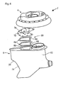
- Figs 3 and 4 show exploded views of the propeller drive 1 in perspective.
- the frame 84 constitutes a separate rigid part (on top in Figs 3 and 4 ) in relation to the lower elastically deformable part of the sealing element 64.
- the shape of the sealing element 64, the wear plate 72 and the opening 74 in the wear plate can also be seen from the figures. These shapes will be described in greater detail below with reference to Fig. 6 .
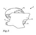
- Fig. 5 shows the propeller drive at an angle from below in assembled state.
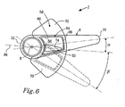
- Fig. 6 shows a diagrammatic illustration of relative positions of the inlet opening 60 of the lower duct section 56 and the outlet opening 62 of the upper duct section 54 at different rotation angles of the underwater housing 6.
- the propellers 10a, 10b are not shown in this schematized view, but they project, as described above, further down on the fore side 12 of the underwater housing 6, on the left side of the figure.
- the inlet opening 60 in the lower duct section 56 is adapted to overlap the opposite outlet opening 62 in the upper duct section 54 fully only within a limited first rotation angle range around a center position for the propeller drive 1 - to be precise the underwater housing 6.
- the center position is illustrated in the figure by the horizontal dot-dash line 96.
- the limited first rotation angle range corresponds to a rotation of the propeller drive 1 - to be precise of the underwater housing 6 - of between 10 and 15° to starboard and port respectively. Full overlapping therefore takes place only within this limited first rotation angle range around the center position 96, which range easily covers typical maneuvers at normal cruising speed or speeds above this.
- the exhaust gases are blown in full or in part directly out of the outlet opening 62 of the upper duct section 54, as is shown by the representation in dashed lines of the underwater housing 6.
- the underwater housing 6 is shown rotated to port (downward in the figure) by an angle ⁇ corresponding to roughly 30°, which results in the inlet opening 60 in the lower duct section 56 being rotated in part past the opposite outlet opening 62 in the upper duct section 54.
- the exhaust gases are then discharged in part at the side of the inlet opening 60 in the lower duct section 56 on a level with the sealing device 64 directly below the hull bottom 2.
- Fig. 6 also shows that the wear plate 72 is designed as part of a sector of a circle around the axis of rotation 8 and thus has an essentially fan-like shape.
- the wear plate 72 extends to the sides to such an extent that the downwardly facing sliding seal surface 70 of the wear plate 72 makes contact of the entire upper contact surface 68 on the sealing element 64 possible throughout the rotation angle range of the propeller drive 1, which is 30° to each side in the embodiment shown.
- the outlet opening 62 in the upper duct section 54 like the opening 74 in the wear plate 72, has an essentially oblong triangular shape with the base facing the axis of rotation 8 and the top facing astern.
- the inlet opening 60 in the lower duct section 56 is essentially of rounded rectangular design and is considerably larger than the outlet opening 62 in the upper duct section 54 so as to be capable of overlapping the same during rotation within said limited first rotation angle range.
- the design of the sliding seal arrangement 58 can be reversed compared with the embodiment shown in the figures.
- some of the references above to "upper” and “lower” consequently no longer apply, as the wear plate 72 is then instead attached firmly around the inlet opening 60 in the lower duct section 56, while the seat 66 is arranged around the outlet opening 62 in the upper duct section 54.
- the orientation of the sealing element 64 also is then reversed so that the frame 84 faces downward instead for contact with the wear plate 72.
- the opening 74 in the wear plate 72 coincides instead with the inlet opening 62 in the lower duct section 56.
- holder means (not shown) can be designed at the seat 66 or in the sealing element 64 for retaining the sealing element 64 during mounting of the underwater housing 6.
- the frame 84 can be designed with a different cross-sectional shape, such as an L shape.
- the embodiment of the propeller drive 1 shown is intended for tractor propellers, the sliding seal arrangement can also be applied to a correspondingly designed propeller drive for pusher propellers (not shown). It is also conceivable, within the scope of the invention, for the rigid part and the elastically deformable part of the sealing element 64 to be produced by a process in which a common, originally homogeneous starting material is given locally different mechanical properties.
Landscapes
- Chemical & Material Sciences (AREA)
- Engineering & Computer Science (AREA)
- Combustion & Propulsion (AREA)
- Mechanical Engineering (AREA)
- Ocean & Marine Engineering (AREA)
- Exhaust Silencers (AREA)
- Sealing Devices (AREA)
- Cylinder Crankcases Of Internal Combustion Engines (AREA)
- Gear Transmission (AREA)
- Pharmaceuticals Containing Other Organic And Inorganic Compounds (AREA)
- Auxiliary Drives, Propulsion Controls, And Safety Devices (AREA)
- Control Of Throttle Valves Provided In The Intake System Or In The Exhaust System (AREA)
Claims (16)
- Propulseur rotatif (1) pour un bateau, ledit propulseur (1) comprenant :- une plaque de fixation supérieure (4) adaptée pour pouvoir être fixée de manière rotative au fond de coque (2) du bateau ;- un boîtier immergé inférieur (6) sur lequel au moins un propulseur (10, 10a, 10b) est monté, lequel boîtier immergé (6) est monté rotatif dans la plaque de fixation (4) par rapport à un axe de rotation (8) essentiellement vertical, et- un conduit d'échappement (50) muni d'une sortie d'échappement (14) située dans le boîtier immergé (6), caractérisé en ce que le conduit d'échappement (50) présente :- une section de conduit supérieure (54) qui s'étend à travers la plaque de fixation (4) et possède une ouverture d'émission (62) située à proximité d'une ouverture d'admission (60) opposée au sein d'une section de conduit inférieure (56) qui s'étend à travers le boîtier immergé (6), l'une parmi lesdites ouverture d'émission (62) et ouverture d'admission (60) chevauchant l'autre au moins à l'intérieur d'une première plage angulaire limitée de rotation du propulseur (1), et- un agencement coulissant (58) formant joint, adapté pour assurer une étanchéité entre lesdites sections de conduit supérieure (54) et inférieure (56), ledit agencement coulissant (58) formant joint comprenant un élément d'étanchéification (64) logé dans un siège (66) autour de l'une parmi lesdites ouverture d'émission (62) et ouverture d'admission (60), cet élément d'étanchéification (64) ayant une surface de contact (68) destinée à un contact coulissant avec une surface coulissante (70) opposée formant joint autour de l'autre parmi lesdites ouverture d'émission (62) et ouverture d'admission (60).
- Propulseur rotatif (1) selon la revendication 1, caractérisé en ce que ladite surface coulissante (70) formant joint est conçue sur une plaque d'usure (72) séparée qui est fixée fermement autour de l'ouverture d'émission (62) au sein de la section de conduit supérieure (54) ou autour de l'ouverture d'admission (60) au sein de la section de conduit inférieure (56) et est munie d'une ouverture (74) qui coïncide essentiellement avec celle de ladite ouverture d'admission (60) ou ouverture d'émission (62) autour de laquelle la plaque d'usure (72) est fixée.
- Propulseur rotatif (1) selon la revendication 1 ou 2, caractérisé en ce que l'élément d'étanchéification (64) est au moins partiellement élastiquement déformable et possède un bord latéral (76), regardant radialement vers l'intérieur, qui est adapté pour, sous l'influence d'une pression de gaz d'échappement dans le conduit échappement (50), être déplacé radialement vers l'extérieur en partie ou en totalité, tandis qu'un bord latéral (78), regardant radialement vers l'extérieur et se trouvant sur l'élément d'étanchéification (64), est adapté pour s'appuyer contre un bord de soutien (80) fixe regardant radialement vers l'intérieur, l'élément d'étanchéification (64) étant adapté pour, par déformation élastique, s'étendre verticalement dans la direction de la surface coulissante (70) formant joint, en conséquence de quoi une pression d'étanchéification accrue contre la surface coulissante (70) formant joint est obtenue pour une pression de gaz d'échappement accrue.
- Propulseur rotatif (1) selon la revendication 3, caractérisé en ce qu'une lèvre d'étanchéification intérieure (88) est conçue à proximité dudit bord latéral (76), regardant radialement vers l'intérieur, de l'élément d'étanchéification (64), cette lèvre d'étanchéification (88) s'appuyant contre le siège (66) de telle manière qu'un canal creux (90) s'étendant tout autour est défini radialement à l'extérieur de ladite lèvre d'étanchéification (88) entre ce bord (92) de l'élément d'étanchéification (64) regardant le siège (66) et le siège (66).
- Propulseur rotatif (1) selon l'une quelconque des revendications précédentes, caractérisé en ce que l'élément d'étanchéification (64) est divisé en une partie élastiquement déformable et une partie essentiellement rigide, la surface de contact (68) de l'élément d'étanchéification (64) étant située sur la partie rigide.
- Propulseur rotatif (1) selon la revendication 5, caractérisé en ce que la partie élastiquement déformable est réalisée en partie ou en totalité en un matériau caoutchouté ou en un matériau possédant des propriétés similaires au caoutchouc, tandis que la partie rigide est réalisée en partie ou en totalité en acier inoxydable ou en plastique.
- Propulseur rotatif (1) selon la revendication 5 ou 6, caractérisé en ce que la partie rigide de l'élément d'étanchéification (64) est conçue comme un châssis (84) dimensionnellement stable avec une section transversale en forme de U, ce châssis (84) accueillant partiellement la partie élastiquement déformable de l'élément d'étanchéification (64).
- Propulseur rotatif (1) selon les revendications 3 et 7, caractérisé en ce que ledit bord de soutien (80) regardant radialement vers l'intérieur est constitué d'un jambage extérieur (82) du châssis (84), tandis que le bord latéral (76) regardant radialement vers l'extérieur et se trouvant sur l'élément d'étanchéification (60) est défini sur la partie élastiquement déformable.
- Propulseur rotatif (1) selon l'une quelconque des revendications 1 à 5, caractérisé en ce que ledit bord de soutien (80) regardant radialement vers l'intérieur est constitué d'un bord de délimitation extérieure (86) pour le siège (66).
- Propulseur rotatif (1) selon l'une quelconque des revendications 5 à 9, caractérisé en ce que la partie rigide constitue une partie séparée en relation avec la partie élastiquement déformable.
- Propulseur rotatif (1) selon l'une quelconque des revendications 5 à 9, caractérisé en ce que la partie rigide est fixée à la partie élastiquement déformable, par exemple par vulcanisation.
- Propulseur rotatif (1) selon l'une quelconque des revendications précédentes, caractérisé en ce que la plaque d'usure (72) est, au moins au niveau de la surface coulissante (70) formant joint, réalisée en un matériau résistant à l'usure et à coefficient de frottement réduit, tel que par exemple du polytétrafluoroéthylène (PTFE).
- Propulseur rotatif (1) selon l'une quelconque des revendications précédentes, caractérisé en ce que ladite première plage angulaire de rotation prédéterminée correspond à une rotation du propulseur (1) comprise entre 10 et 15° par rapport à bâbord et à tribord respectivement.
- Propulseur rotatif (1) selon l'une quelconque des revendications précédentes, caractérisé en ce que le propulseur (1) est adapté pour au moins une hélice de traction (10, 10a, 10b).
- Propulseur rotatif (1) selon l'une quelconque des revendications précédentes, caractérisé en ce que le propulseur (1) est adapté pour une combinaison de propulseurs jumelés comprenant un propulseur avant (10a) et un propulseur arrière (10b).
- Propulseur rotatif (1) selon la revendication 14, caractérisé en ce que les sections de conduit supérieure (54) et inférieure (56) du conduit d'échappement (50) sont situées vers l'arrière de l'axe de rotation (8) du propulseur (1).
Applications Claiming Priority (2)
| Application Number | Priority Date | Filing Date | Title |
|---|---|---|---|
| SE0302064A SE525478C2 (sv) | 2003-07-11 | 2003-07-11 | Vridbart propellerdrev för en båt |
| PCT/SE2004/000627 WO2005005249A1 (fr) | 2003-07-11 | 2004-04-23 | Propulseur rotatif pour bateau |
Publications (2)
| Publication Number | Publication Date |
|---|---|
| EP1646552A1 EP1646552A1 (fr) | 2006-04-19 |
| EP1646552B1 true EP1646552B1 (fr) | 2010-12-29 |
Family
ID=27764985
Family Applications (1)
| Application Number | Title | Priority Date | Filing Date |
|---|---|---|---|
| EP04729342A Expired - Lifetime EP1646552B1 (fr) | 2003-07-11 | 2004-04-23 | Propulseur rotatif pour bateau |
Country Status (6)
| Country | Link |
|---|---|
| US (1) | US7186157B2 (fr) |
| EP (1) | EP1646552B1 (fr) |
| AT (1) | ATE493331T1 (fr) |
| DE (1) | DE602004030797D1 (fr) |
| SE (1) | SE525478C2 (fr) |
| WO (1) | WO2005005249A1 (fr) |
Families Citing this family (17)
| Publication number | Priority date | Publication date | Assignee | Title |
|---|---|---|---|---|
| US7438615B2 (en) * | 2004-05-28 | 2008-10-21 | Ab Volvo | Outboard drive for boats |
| US7387556B1 (en) * | 2006-03-01 | 2008-06-17 | Brunswick Corporation | Exhaust system for a marine propulsion device having a driveshaft extending vertically through a bottom portion of a boat hull |
| US20070254987A1 (en) * | 2006-04-26 | 2007-11-01 | Associated Materials, Inc. | Siding panel formed of polymer and wood flour |
| WO2008136712A1 (fr) * | 2007-05-03 | 2008-11-13 | Ab Volvo Penta | Procédé permettant de vidanger des liquides présents dans unité contenant un liquide - moteur,machine ou transmission - et adaptateur de vidange correspondant |
| US7850496B1 (en) | 2008-01-11 | 2010-12-14 | Brunswick Corporation | Lubrication system of a marine propulsion device |
| DE102008042599A1 (de) | 2008-10-02 | 2010-04-08 | Zf Friedrichshafen Ag | Steuereinrichtung für einen Schiffsantrieb |
| DE102009000991A1 (de) | 2009-02-18 | 2010-08-19 | Zf Friedrichshafen Ag | In einen Bootsrumpf einsetzbares Zwischenstück |
| DE102009000993A1 (de) * | 2009-02-18 | 2010-08-19 | Zf Friedrichshafen Ag | Steuereinrichtung und Bootsantrieb mit Steuereinrichtung |
| DE102009000994A1 (de) | 2009-02-18 | 2010-08-19 | Zf Friedrichshafen Ag | Dichtungsanordnung für einen schwenkbaren Bootsantrieb |
| WO2010107345A1 (fr) * | 2009-03-20 | 2010-09-23 | Ab Volvo Penta | Procédé et système de commande des gaz d'échappement provenant d'un moteur |
| DE102010001707A1 (de) | 2010-02-09 | 2011-08-11 | ZF Friedrichshafen AG, 88046 | Verfahren zum Manövrieren einer Yacht |
| DE102012210727A1 (de) * | 2012-06-25 | 2014-01-02 | Zf Friedrichshafen Ag | Bootsantrieb |
| NO2884749T3 (fr) | 2013-09-11 | 2018-06-09 | ||
| US9403589B2 (en) | 2013-11-21 | 2016-08-02 | Globe Motors, Inc. | Manual override for steering actuator |
| US9896172B1 (en) | 2016-01-21 | 2018-02-20 | Brunswick Corporation | Apparatuses and methods for servicing lubrication in a marine drive |
| EP4043334B1 (fr) * | 2021-02-12 | 2023-10-25 | Volvo Penta Corporation | Groupe propulseur pour un navire |
| IT202300022965A1 (it) | 2023-10-31 | 2025-05-01 | Transfluid S P A | Sistema di propulsione sail-drive perfezionato per imbarcazioni |
Family Cites Families (10)
| Publication number | Priority date | Publication date | Assignee | Title |
|---|---|---|---|---|
| US3919965A (en) * | 1971-11-01 | 1975-11-18 | Ross Robertson | Boat propeller mounting and steering mechanism |
| US4911666A (en) * | 1987-06-15 | 1990-03-27 | Us Marine Corporation | Boat propulsion device with internal exhaust |
| JP3046398B2 (ja) * | 1991-06-06 | 2000-05-29 | 三信工業株式会社 | 船舶推進機 |
| SE470355B (sv) * | 1992-06-22 | 1994-01-31 | Volvo Penta Ab | Upphängningsanordningen, för båtpropellerdrev, med ramelement i båtakterspegeln |
| SE516576C2 (sv) * | 1999-03-16 | 2002-01-29 | Volvo Penta Ab | Drivaggregat i en båt innefattande motroterande, dragande propellrar anordnade på ett undervattenshus med aktre roderblad samt drivinstallation med två sådana drivaggregat |
| SE516579C2 (sv) * | 1999-03-16 | 2002-01-29 | Volvo Penta Ab | Drivaggregat i en båt innefattande motroterande, dragande propellrar anordnade på ett undervattenshus och där akterpropellern arbetar kaviterande samt drivinstallation med två sådana drivaggregat |
| SE516559C2 (sv) * | 1999-03-16 | 2002-01-29 | Volvo Penta Ab | Drivaggregat i en båt innefattande motroterande, dragande propellrar anordnade på ett undervattenshus med ett torpedliknande parti samt drivinstallation med två sådana drivaggregat |
| SE516560C2 (sv) * | 1999-03-16 | 2002-01-29 | Volvo Penta Ab | Drivaggregat i en båt innefattande motroterande, dragande propellrar anordnade på ett undervattenshus med aktre roderblad och avgasutblås samt drivinstallation med två sådana drivaggregat |
| SE518844C2 (sv) * | 2000-02-02 | 2002-11-26 | Volvo Penta Ab | Drivaggregat i en båt |
| US6508681B1 (en) * | 2000-06-05 | 2003-01-21 | Bombardier Motor Corporation Of America | Low friction exhaust bellows and techniques for constructing and assembling such bellows |
-
2003
- 2003-07-11 SE SE0302064A patent/SE525478C2/sv not_active IP Right Cessation
-
2004
- 2004-04-23 DE DE602004030797T patent/DE602004030797D1/de not_active Expired - Lifetime
- 2004-04-23 EP EP04729342A patent/EP1646552B1/fr not_active Expired - Lifetime
- 2004-04-23 WO PCT/SE2004/000627 patent/WO2005005249A1/fr not_active Ceased
- 2004-04-23 AT AT04729342T patent/ATE493331T1/de not_active IP Right Cessation
-
2006
- 2006-01-11 US US11/306,796 patent/US7186157B2/en not_active Expired - Lifetime
Also Published As
| Publication number | Publication date |
|---|---|
| US20060199452A1 (en) | 2006-09-07 |
| SE0302064L (sv) | 2005-01-12 |
| US7186157B2 (en) | 2007-03-06 |
| WO2005005249A1 (fr) | 2005-01-20 |
| EP1646552A1 (fr) | 2006-04-19 |
| DE602004030797D1 (de) | 2011-02-10 |
| SE525478C2 (sv) | 2005-03-01 |
| ATE493331T1 (de) | 2011-01-15 |
| SE0302064D0 (sv) | 2003-07-11 |
Similar Documents
| Publication | Publication Date | Title |
|---|---|---|
| EP1646552B1 (fr) | Propulseur rotatif pour bateau | |
| US5421753A (en) | Marine jet drive | |
| US3889623A (en) | Jet propulsion unit for boats | |
| US5720636A (en) | Marine propulsor | |
| US4832642A (en) | Outboard boat propulsion installation | |
| US5722866A (en) | Propulsion arrangement for a marine vessel | |
| EP1169221A1 (fr) | Dispositif d'entrainement d'un bateau | |
| US6238257B1 (en) | Surface vessel with a waterjet propulsion system | |
| US6279499B1 (en) | Rotational jet-drive bow thruster for a marine propulsion system | |
| US4652244A (en) | Propulsion unit for water craft | |
| AU636858B2 (en) | Trimming system for boat propulsion system | |
| KR100649174B1 (ko) | 워터제트 추진 시스템을 갖는 수상 선박 | |
| US5145428A (en) | Shrouded propeller system for a sailboat | |
| US6024614A (en) | High performance marine propulsion system | |
| EP1512623B1 (fr) | Dispositif pour gouverner un bateau | |
| US5766048A (en) | Exhaust system for outboard drive | |
| EP4344991B1 (fr) | Système d'entraînement marin avec surface de palier de centrage | |
| EP0159144A1 (fr) | Propulseur azimutal pour bateau | |
| AU637067B2 (en) | Steering mechanism in a boat propulsion system | |
| US12319396B2 (en) | Vessel propelling system and assembly | |
| US3224408A (en) | Propulsion device | |
| US3901176A (en) | Hydraulic jet propulsion apparatus suitable for waterborne vessels | |
| JP2004231102A (ja) | 船体とプロペラの配置構造 | |
| US20150064997A1 (en) | Boat Hull Construction | |
| JPS58122290A (ja) | 舶用推進装置 |
Legal Events
| Date | Code | Title | Description |
|---|---|---|---|
| PUAI | Public reference made under article 153(3) epc to a published international application that has entered the european phase |
Free format text: ORIGINAL CODE: 0009012 |
|
| 17P | Request for examination filed |
Effective date: 20060213 |
|
| AK | Designated contracting states |
Kind code of ref document: A1 Designated state(s): AT BE BG CH CY CZ DE DK EE ES FI FR GB GR HU IE IT LI LU MC NL PL PT RO SE SI SK TR |
|
| DAX | Request for extension of the european patent (deleted) | ||
| GRAP | Despatch of communication of intention to grant a patent |
Free format text: ORIGINAL CODE: EPIDOSNIGR1 |
|
| GRAS | Grant fee paid |
Free format text: ORIGINAL CODE: EPIDOSNIGR3 |
|
| GRAA | (expected) grant |
Free format text: ORIGINAL CODE: 0009210 |
|
| AK | Designated contracting states |
Kind code of ref document: B1 Designated state(s): AT BE BG CH CY CZ DE DK EE ES FI FR GB GR HU IE IT LI LU MC NL PL PT RO SE SI SK TR |
|
| REG | Reference to a national code |
Ref country code: GB Ref legal event code: FG4D |
|
| REG | Reference to a national code |
Ref country code: CH Ref legal event code: EP |
|
| REG | Reference to a national code |
Ref country code: IE Ref legal event code: FG4D |
|
| REF | Corresponds to: |
Ref document number: 602004030797 Country of ref document: DE Date of ref document: 20110210 Kind code of ref document: P |
|
| REG | Reference to a national code |
Ref country code: DE Ref legal event code: R096 Ref document number: 602004030797 Country of ref document: DE Effective date: 20110210 |
|
| REG | Reference to a national code |
Ref country code: NL Ref legal event code: VDEP Effective date: 20101229 |
|
| PG25 | Lapsed in a contracting state [announced via postgrant information from national office to epo] |
Ref country code: SI Free format text: LAPSE BECAUSE OF FAILURE TO SUBMIT A TRANSLATION OF THE DESCRIPTION OR TO PAY THE FEE WITHIN THE PRESCRIBED TIME-LIMIT Effective date: 20101229 Ref country code: SE Free format text: LAPSE BECAUSE OF FAILURE TO SUBMIT A TRANSLATION OF THE DESCRIPTION OR TO PAY THE FEE WITHIN THE PRESCRIBED TIME-LIMIT Effective date: 20101229 Ref country code: CY Free format text: LAPSE BECAUSE OF FAILURE TO SUBMIT A TRANSLATION OF THE DESCRIPTION OR TO PAY THE FEE WITHIN THE PRESCRIBED TIME-LIMIT Effective date: 20101229 Ref country code: BG Free format text: LAPSE BECAUSE OF FAILURE TO SUBMIT A TRANSLATION OF THE DESCRIPTION OR TO PAY THE FEE WITHIN THE PRESCRIBED TIME-LIMIT Effective date: 20110329 Ref country code: FI Free format text: LAPSE BECAUSE OF FAILURE TO SUBMIT A TRANSLATION OF THE DESCRIPTION OR TO PAY THE FEE WITHIN THE PRESCRIBED TIME-LIMIT Effective date: 20101229 Ref country code: AT Free format text: LAPSE BECAUSE OF FAILURE TO SUBMIT A TRANSLATION OF THE DESCRIPTION OR TO PAY THE FEE WITHIN THE PRESCRIBED TIME-LIMIT Effective date: 20101229 |
|
| PG25 | Lapsed in a contracting state [announced via postgrant information from national office to epo] |
Ref country code: CZ Free format text: LAPSE BECAUSE OF FAILURE TO SUBMIT A TRANSLATION OF THE DESCRIPTION OR TO PAY THE FEE WITHIN THE PRESCRIBED TIME-LIMIT Effective date: 20101229 Ref country code: GR Free format text: LAPSE BECAUSE OF FAILURE TO SUBMIT A TRANSLATION OF THE DESCRIPTION OR TO PAY THE FEE WITHIN THE PRESCRIBED TIME-LIMIT Effective date: 20110330 Ref country code: PT Free format text: LAPSE BECAUSE OF FAILURE TO SUBMIT A TRANSLATION OF THE DESCRIPTION OR TO PAY THE FEE WITHIN THE PRESCRIBED TIME-LIMIT Effective date: 20110429 Ref country code: EE Free format text: LAPSE BECAUSE OF FAILURE TO SUBMIT A TRANSLATION OF THE DESCRIPTION OR TO PAY THE FEE WITHIN THE PRESCRIBED TIME-LIMIT Effective date: 20101229 Ref country code: BE Free format text: LAPSE BECAUSE OF FAILURE TO SUBMIT A TRANSLATION OF THE DESCRIPTION OR TO PAY THE FEE WITHIN THE PRESCRIBED TIME-LIMIT Effective date: 20101229 Ref country code: ES Free format text: LAPSE BECAUSE OF FAILURE TO SUBMIT A TRANSLATION OF THE DESCRIPTION OR TO PAY THE FEE WITHIN THE PRESCRIBED TIME-LIMIT Effective date: 20110409 |
|
| PG25 | Lapsed in a contracting state [announced via postgrant information from national office to epo] |
Ref country code: NL Free format text: LAPSE BECAUSE OF FAILURE TO SUBMIT A TRANSLATION OF THE DESCRIPTION OR TO PAY THE FEE WITHIN THE PRESCRIBED TIME-LIMIT Effective date: 20101229 Ref country code: PL Free format text: LAPSE BECAUSE OF FAILURE TO SUBMIT A TRANSLATION OF THE DESCRIPTION OR TO PAY THE FEE WITHIN THE PRESCRIBED TIME-LIMIT Effective date: 20101229 Ref country code: SK Free format text: LAPSE BECAUSE OF FAILURE TO SUBMIT A TRANSLATION OF THE DESCRIPTION OR TO PAY THE FEE WITHIN THE PRESCRIBED TIME-LIMIT Effective date: 20101229 Ref country code: RO Free format text: LAPSE BECAUSE OF FAILURE TO SUBMIT A TRANSLATION OF THE DESCRIPTION OR TO PAY THE FEE WITHIN THE PRESCRIBED TIME-LIMIT Effective date: 20101229 |
|
| PG25 | Lapsed in a contracting state [announced via postgrant information from national office to epo] |
Ref country code: DK Free format text: LAPSE BECAUSE OF FAILURE TO SUBMIT A TRANSLATION OF THE DESCRIPTION OR TO PAY THE FEE WITHIN THE PRESCRIBED TIME-LIMIT Effective date: 20101229 |
|
| PLBE | No opposition filed within time limit |
Free format text: ORIGINAL CODE: 0009261 |
|
| STAA | Information on the status of an ep patent application or granted ep patent |
Free format text: STATUS: NO OPPOSITION FILED WITHIN TIME LIMIT |
|
| PG25 | Lapsed in a contracting state [announced via postgrant information from national office to epo] |
Ref country code: MC Free format text: LAPSE BECAUSE OF NON-PAYMENT OF DUE FEES Effective date: 20110430 |
|
| REG | Reference to a national code |
Ref country code: CH Ref legal event code: PL |
|
| 26N | No opposition filed |
Effective date: 20110930 |
|
| REG | Reference to a national code |
Ref country code: FR Ref legal event code: ST Effective date: 20111230 |
|
| REG | Reference to a national code |
Ref country code: DE Ref legal event code: R097 Ref document number: 602004030797 Country of ref document: DE Effective date: 20110930 |
|
| PG25 | Lapsed in a contracting state [announced via postgrant information from national office to epo] |
Ref country code: CH Free format text: LAPSE BECAUSE OF NON-PAYMENT OF DUE FEES Effective date: 20110430 Ref country code: LI Free format text: LAPSE BECAUSE OF NON-PAYMENT OF DUE FEES Effective date: 20110430 Ref country code: FR Free format text: LAPSE BECAUSE OF NON-PAYMENT OF DUE FEES Effective date: 20110502 |
|
| REG | Reference to a national code |
Ref country code: IE Ref legal event code: MM4A |
|
| PG25 | Lapsed in a contracting state [announced via postgrant information from national office to epo] |
Ref country code: IE Free format text: LAPSE BECAUSE OF NON-PAYMENT OF DUE FEES Effective date: 20110423 |
|
| PG25 | Lapsed in a contracting state [announced via postgrant information from national office to epo] |
Ref country code: LU Free format text: LAPSE BECAUSE OF NON-PAYMENT OF DUE FEES Effective date: 20110423 |
|
| PG25 | Lapsed in a contracting state [announced via postgrant information from national office to epo] |
Ref country code: TR Free format text: LAPSE BECAUSE OF FAILURE TO SUBMIT A TRANSLATION OF THE DESCRIPTION OR TO PAY THE FEE WITHIN THE PRESCRIBED TIME-LIMIT Effective date: 20101229 |
|
| PG25 | Lapsed in a contracting state [announced via postgrant information from national office to epo] |
Ref country code: HU Free format text: LAPSE BECAUSE OF FAILURE TO SUBMIT A TRANSLATION OF THE DESCRIPTION OR TO PAY THE FEE WITHIN THE PRESCRIBED TIME-LIMIT Effective date: 20101229 |
|
| PGFP | Annual fee paid to national office [announced via postgrant information from national office to epo] |
Ref country code: IT Payment date: 20230421 Year of fee payment: 20 Ref country code: DE Payment date: 20230427 Year of fee payment: 20 |
|
| PGFP | Annual fee paid to national office [announced via postgrant information from national office to epo] |
Ref country code: GB Payment date: 20230418 Year of fee payment: 20 |
|
| REG | Reference to a national code |
Ref country code: DE Ref legal event code: R071 Ref document number: 602004030797 Country of ref document: DE |
|
| REG | Reference to a national code |
Ref country code: GB Ref legal event code: PE20 Expiry date: 20240422 |
|
| PG25 | Lapsed in a contracting state [announced via postgrant information from national office to epo] |
Ref country code: GB Free format text: LAPSE BECAUSE OF EXPIRATION OF PROTECTION Effective date: 20240422 |
|
| PG25 | Lapsed in a contracting state [announced via postgrant information from national office to epo] |
Ref country code: GB Free format text: LAPSE BECAUSE OF EXPIRATION OF PROTECTION Effective date: 20240422 |