EP1646552B1 - Turning propeller drive for a boat - Google Patents
Turning propeller drive for a boat Download PDFInfo
- Publication number
- EP1646552B1 EP1646552B1 EP04729342A EP04729342A EP1646552B1 EP 1646552 B1 EP1646552 B1 EP 1646552B1 EP 04729342 A EP04729342 A EP 04729342A EP 04729342 A EP04729342 A EP 04729342A EP 1646552 B1 EP1646552 B1 EP 1646552B1
- Authority
- EP
- European Patent Office
- Prior art keywords
- propeller drive
- sealing element
- propeller
- sliding seal
- rotatable propeller
- Prior art date
- Legal status (The legal status is an assumption and is not a legal conclusion. Google has not performed a legal analysis and makes no representation as to the accuracy of the status listed.)
- Expired - Lifetime
Links
- 238000007789 sealing Methods 0.000 claims abstract description 76
- 239000000463 material Substances 0.000 claims description 8
- -1 for example Substances 0.000 claims description 6
- 229920001343 polytetrafluoroethylene Polymers 0.000 claims description 6
- 239000004810 polytetrafluoroethylene Substances 0.000 claims description 6
- 239000002783 friction material Substances 0.000 claims description 3
- 239000004033 plastic Substances 0.000 claims description 3
- 239000010935 stainless steel Substances 0.000 claims description 3
- 229910001220 stainless steel Inorganic materials 0.000 claims description 3
- 238000004073 vulcanization Methods 0.000 claims description 3
- 230000005489 elastic deformation Effects 0.000 claims description 2
- 239000007789 gas Substances 0.000 description 16
- 230000000694 effects Effects 0.000 description 4
- 238000002485 combustion reaction Methods 0.000 description 3
- 230000007246 mechanism Effects 0.000 description 3
- 230000008901 benefit Effects 0.000 description 2
- 230000002093 peripheral effect Effects 0.000 description 2
- XLYOFNOQVPJJNP-UHFFFAOYSA-N water Substances O XLYOFNOQVPJJNP-UHFFFAOYSA-N 0.000 description 2
- 238000010276 construction Methods 0.000 description 1
- 238000013016 damping Methods 0.000 description 1
- 238000007599 discharging Methods 0.000 description 1
- 230000002349 favourable effect Effects 0.000 description 1
- 238000000034 method Methods 0.000 description 1
- 230000008569 process Effects 0.000 description 1
- 239000007858 starting material Substances 0.000 description 1
- 230000007704 transition Effects 0.000 description 1
Images


Classifications
-
- B—PERFORMING OPERATIONS; TRANSPORTING
- B63—SHIPS OR OTHER WATERBORNE VESSELS; RELATED EQUIPMENT
- B63H—MARINE PROPULSION OR STEERING
- B63H20/00—Outboard propulsion units, e.g. outboard motors or Z-drives; Arrangements thereof on vessels
- B63H20/24—Arrangements, apparatus and methods for handling exhaust gas in outboard drives, e.g. exhaust gas outlets
- B63H20/245—Exhaust gas outlets
Definitions
- the present invention relates to a rotatable propeller drive for a boat, according to the characteristics of the preamble of independent claim 1.
- the propeller drive is provided with an exhaust duct for discharging exhaust gases from an internal combustion engine connected to the propeller drive.
- the propeller drive has an upper fixing plate for rotationally fixed attachment to the hull bottom of the boat, and a lower underwater housing on which at least one propeller is mounted.
- the underwater housing is mounted rotatably in the fixing plate, and the invention concerns in particular sealing between an upper duct section of the exhaust duct arranged in the fixing plate and a lower duct section of the exhaust duct arranged in the underwater housing, where the lower duct section is displaced in relation to the upper duct section when the propeller drive is rotated.
- a seal is required between the two duct sections in order to avoid exhaust gas leakage when the boat is driven, at least above a certain minimum speed.
- This minimum speed may be, for example, 3-5 knots and can also be said to correspond to a practical upper limit for driving the boat in a harbor area or in proximity to another mooring. If exhaust gases are allowed to leak out between the duct sections when the boat is driven above said minimum speed, exhaust gases may be drawn into the boat via the stern portion of the boat, where a local negative pressure then prevails. This effect is sometimes called wagon-back effect.
- the invention provides a rotatable propeller drive for a boat, where said propeller drive comprises:
- the sliding seal surface is designed on a separate wear plate which is attached firmly either around the outlet opening in the upper duct section or around the inlet opening in the lower duct section and is provided with an opening which essentially coincides with that of said inlet opening or outlet opening around which the wear plate is attached.
- the sealing element is at least partly elastically deformable and has a radially inwardly facing side edge which is adapted so as, under the influence of an exhaust gas pressure in the exhaust duct, to be displaced radially outwardly fully or partly, while a radially outwardly facing side edge on the sealing element is adapted to bear against a fixed radially inwardly facing stay edge, the sealing element being adapted so as, by elastic deformation, to expand vertically in the direction of the sliding seal surface, as a result of which an increased sealing pressure against the sliding seal surface is obtained at increased exhaust gas pressure.
- an inner sealing lip is designed in proximity to said radially inwardly facing side edge of the sealing element, which sealing lip bears against the seat in such a way that a hollow channel extending all around is defined radially outside said sealing lip between that edge of the sealing element facing the seat and the seat.
- the sealing element is divided into a lower elastically deformable part and an essentially rigid upper part, where the contact surface of the sealing element is located on the rigid part.
- the elastically deformable part is suitably made wholly or partly from a rubber material or a material with rubber-like properties, while the rigid part is made wholly or partly from stainless steel or plastic.
- the rigid part of the sealing element is preferably designed as a dimensionally stable frame with a U-shaped cross section, which frame partly accommodates the elastically deformable part of the sealing element.
- the radially inwardly facing stay edge mentioned above consists of an outer leg portion of the frame, while the radially outwardly facing side edge on the sealing element is defined on the elastically deformable part.
- the radially inwardly facing stay edge consists of an outer delimiting edge for the seat.
- the rigid part constitutes a separate part in relation to the elastically deformable part.
- the rigid part is attached to the elastically deformable part, for example by vulcanization.
- the wear plate is, at least at the sliding seal surface, made from a hard-wearing low-friction material, such as, for example, polytetrafluoroethylene (PTFE).
- a hard-wearing low-friction material such as, for example, polytetrafluoroethylene (PTFE).
- Said limited first rotation angle range preferably corresponds to a rotation of the propeller drive of between 10 and 15° to starboard and port respectively.
- the propeller drive is adapted for at least one tractor propeller.
- a twin propeller combination of a fore propeller and an aft propeller is especially advantageous.
- the upper and lower duct sections of the exhaust duct are preferably located astern of the axis of rotation of the propeller drive.
- reference number 1 designates generally a rotatable propeller drive according to an exemplary embodiment of the invention.
- the propeller drive 1 is attached to the hull bottom 2 on a boat (not shown) and comprises an upper fixing plate 4 adapted for rotationally fixed attachment to the hull bottom 2 of the boat.
- a lower underwater housing 6 is mounted rotatably in the fixing plate 4 about an essentially vertical axis of rotation 8.
- a tractor propeller 10 is arranged on the underwater housing 6.
- the propeller consists of a twin propeller combination of a fore propeller 10a and an aft propeller 10b rotating in the opposite direction, both of which are illustrated diagrammatically in Fig. 1 and located on the fore side 12 of the underwater housing 6.
- tractor instead of pusher propellers on a propeller drive 1 of this type is that the propellers 10a, 10b work in undisturbed water, as the underwater housing 6 lies behind the propellers 10a, 10b.
- the fore propeller 10a is three-bladed (not shown in Fig. 1 ), while the aft propeller 10b is four-bladed.
- the aft propeller 10b therefore has one blade more than the fore propeller 10a, which is known per se in rotatable propeller drives.
- the blade areas (not shown) of the propellers 10a, 10b are moreover adapted to one another in such a way that the aft propeller 10b works in a cavitating way within a predetermined upper speed range, while the fore propeller 10a works in a non-cavitating way.
- the boat (not shown) can be equipped with a single propeller drive 1, or alternatively with a number of propeller drives 1, normally in a twinned mounting (not shown), where two propeller drives 1 are mounted next to one another, increased maneuverability then being obtained.
- the hull bottom 2 is designed with an opening 18, which is surrounded by a vertical shaft 20, which projects up into the hull bottom 2.
- the shaft 20 is preferably cast in one piece with the hull bottom 2 and is designed with an inwardly directed peripheral flange 22, which has an essentially triangular cross section in the illustrative embodiment shown.
- the shaft 20 with the flange 22 forms the mounting arrangement for the fixing plate 4 of the propeller drive 1, which grips around the flange 22 via a pair of intermediate vibration-damping and sealing elastic rings 24 and 26.
- An upper locking ring 28 is adapted to be fixed to the fixing plate 4 by means of, for example, bolts 30 (of which only the bolt heads are shown partly in Fig. 1 ) when the propeller drive 1 is mounted.
- An internal combustion engine (not shown) drives - via an input shaft 32 in a reversing gear mechanism 34 - a vertical drive shaft 36, which, in the illustrative embodiment shown, coincides with the geometrical axis of rotation 8 (illustrated by dot/dash line), referred to in the introduction, of the propeller drive 1.
- the vertical drive shaft 36 is coupled to two horizontal and concentric propeller shafts 40, 42, of which the propeller shaft 42 is a hollow shaft through which the propeller shaft 40 extends.
- the propeller shaft 40 drives the fore propeller 10a, while the propeller shaft 42 drives the aft propeller 10b.
- the rotation of the underwater housing 6 of the propeller drive 1 is brought about by a servomotor 44, via a gear rim 46 connected to the underwater housing 6.
- An exhaust pipe 48 extends from the internal combustion engine (not shown) and on, through an exhaust duct 50 in the propeller drive 1, to said exhaust exit 14 in the aft side 16 of the underwater housing 6.
- the exhaust duct 50 has an upper duct section 54 which extends through the fixing plate 4, and a lower duct section 56 which extends through the underwater housing 6 and at the bottom, on a level with the propeller shafts 40 and 42, runs into the exhaust exit 14.
- the upper and lower duct sections 54 and 56 of the exhaust duct are located astern of the axis of rotation 8 of the propeller drive 1 in the embodiment shown.
- a sliding seal arrangement 58 is adapted for sealing between said upper and lower duct sections 54 and 56.
- Fig. 2 an enlarged part-section through the sliding seal arrangement 58 is shown in Fig. 2 , which can advantageously be looked at during the following description of the construction of the sliding seal arrangement 58.
- the sliding seal arrangement 58 comprises an inlet opening 60 designed in the lower duct section 56, which inlet opening 60 overlaps an opposite outlet opening 62 in the upper duct section 54 at least within a limited first rotation angle range for the propeller drive 1.
- a sealing element 64 extending all around is accommodated in a seat 66 around the inlet opening 60 in the lower duct section 56.
- the sealing element 64 has an upper contact surface 68 for contact with an opposite, downwardly directed sliding seal surface 70 around the outlet opening 62 in the upper duct section 54.
- the downwardly directed sliding seal surface 70 is, in the embodiment shown, designed on a separate wear plate 72, which is attached firmly to the fixing plate 4 around the outlet opening 62 in the upper duct section 54 by means of screws (not shown) or other suitable fixing elements.
- the wear plate 72 is arranged exchangeably, in order for it to be possible if required to replace a worn wear plate with a new wear plate.
- the wear plate 72 is also provided with an opening 74 which essentially coincides with the outlet opening 62.
- the wear plate 72 is, at least at the downwardly directed sliding seal surface 70, made from a hard-wearing low-friction material, such as, for example, polytetrafluoroethylene (PTFE).
- PTFE polytetrafluoroethylene
- the sealing element 64 is designed to be at least partly elastically deformable and has a radially inwardly facing side edge 76. Under the influence of an exhaust gas pressure in the exhaust duct 50, the inwardly facing side edge 76 is displaced radially outward - that is to say to the right in Fig. 2 - while a radially outwardly facing side edge 78 on the sealing element 64 bears against a fixed, radially inwardly facing stay edge 80.
- the elastically deformable sealing element 64 is therefore compressed in the radially outward direction under the influence of the exhaust gas pressure, which results in it expanding vertically in the direction of the downwardly directed sliding seal surface 70 on the wear plate 72, as a result of which an increased sealing pressure against the sliding seal surface 70 is obtained at increased exhaust gas pressure.
- the fixed stay edge 80 is designed in an outer leg portion 82 of a dimensionally stable frame 84 with a downwardly directed, essentially rectangular U-shaped cross section.
- the frame 84 and its function will be described in greater detail later in this description.
- the sealing element 64 can be said to be divided into a lower elastically deformable part and a rigid upper part.
- the lower elastically deformable part is made wholly or partly from a rubber material or a material with rubber-like properties
- the rigid upper part in the embodiment shown, consists of the U-shaped frame 84 described above.
- the frame 84 can suitably be made wholly or partly from stainless steel or plastic, but other materials suitable for the purpose can also be used.
- the upper contact surface 68 of the sealing element 64 in contact with the downwardly directed sliding seal surface 70 on the wear plate 72 is, with such a definition, located on the rigid upper part, that is to say on the frame 84.
- the frame 84 is, owing to its U shape, designed in such a way that it partly accommodates the lower, elastically deformable part of the sealing element 64.
- the radially outwardly facing side edge 78 on the sealing element 64 is defined on the lower, elastically deformable part and is therefore adapted for contact with the fixed stay edge 80 in the outer leg portion 82 of the frame 84.
- the frame 84 can either constitute a separate part in relation to the lower elastically deformable part of the sealing element 64, or the frame 84 can be attached to the lower elastically deformable part, for example by vulcanization.
- the stay edge 80 consists instead of an outer delimiting edge 86 for the seat 66 around the inlet opening 60 in the lower duct section 56.
- the outer delimiting edge 86 also serves as a positioning aid when the sealing element 64 is placed in the seat 66 in connection with mounting of the propeller drive 1.
- an inner sealing lip 88 is designed in proximity to the radially inwardly facing side edge 76 of the sealing element 64.
- the sealing lip 88 bears downwardly against the seat 66 in such a way that a hollow channel 90 extending all around is defined radially outside the sealing lip 88 between that edge 92 of the sealing element 64 facing the seat 66 and the seat 66.
- that edge of the sealing element 64 facing the seat 66, its inwardly facing side edge 76 and its outwardly facing side edge 78 are all of clearly concave design in the embodiment shown.
- the concave design results in said inner sealing lip 88 and also a corresponding outer sealing lip 94, which also bears against the seat 66.
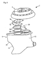
- Figs 3 and 4 show exploded views of the propeller drive 1 in perspective.
- the frame 84 constitutes a separate rigid part (on top in Figs 3 and 4 ) in relation to the lower elastically deformable part of the sealing element 64.
- the shape of the sealing element 64, the wear plate 72 and the opening 74 in the wear plate can also be seen from the figures. These shapes will be described in greater detail below with reference to Fig. 6 .
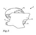
- Fig. 5 shows the propeller drive at an angle from below in assembled state.
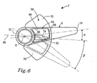
- Fig. 6 shows a diagrammatic illustration of relative positions of the inlet opening 60 of the lower duct section 56 and the outlet opening 62 of the upper duct section 54 at different rotation angles of the underwater housing 6.
- the propellers 10a, 10b are not shown in this schematized view, but they project, as described above, further down on the fore side 12 of the underwater housing 6, on the left side of the figure.
- the inlet opening 60 in the lower duct section 56 is adapted to overlap the opposite outlet opening 62 in the upper duct section 54 fully only within a limited first rotation angle range around a center position for the propeller drive 1 - to be precise the underwater housing 6.
- the center position is illustrated in the figure by the horizontal dot-dash line 96.
- the limited first rotation angle range corresponds to a rotation of the propeller drive 1 - to be precise of the underwater housing 6 - of between 10 and 15° to starboard and port respectively. Full overlapping therefore takes place only within this limited first rotation angle range around the center position 96, which range easily covers typical maneuvers at normal cruising speed or speeds above this.
- the exhaust gases are blown in full or in part directly out of the outlet opening 62 of the upper duct section 54, as is shown by the representation in dashed lines of the underwater housing 6.
- the underwater housing 6 is shown rotated to port (downward in the figure) by an angle ⁇ corresponding to roughly 30°, which results in the inlet opening 60 in the lower duct section 56 being rotated in part past the opposite outlet opening 62 in the upper duct section 54.
- the exhaust gases are then discharged in part at the side of the inlet opening 60 in the lower duct section 56 on a level with the sealing device 64 directly below the hull bottom 2.
- Fig. 6 also shows that the wear plate 72 is designed as part of a sector of a circle around the axis of rotation 8 and thus has an essentially fan-like shape.
- the wear plate 72 extends to the sides to such an extent that the downwardly facing sliding seal surface 70 of the wear plate 72 makes contact of the entire upper contact surface 68 on the sealing element 64 possible throughout the rotation angle range of the propeller drive 1, which is 30° to each side in the embodiment shown.
- the outlet opening 62 in the upper duct section 54 like the opening 74 in the wear plate 72, has an essentially oblong triangular shape with the base facing the axis of rotation 8 and the top facing astern.
- the inlet opening 60 in the lower duct section 56 is essentially of rounded rectangular design and is considerably larger than the outlet opening 62 in the upper duct section 54 so as to be capable of overlapping the same during rotation within said limited first rotation angle range.
- the design of the sliding seal arrangement 58 can be reversed compared with the embodiment shown in the figures.
- some of the references above to "upper” and “lower” consequently no longer apply, as the wear plate 72 is then instead attached firmly around the inlet opening 60 in the lower duct section 56, while the seat 66 is arranged around the outlet opening 62 in the upper duct section 54.
- the orientation of the sealing element 64 also is then reversed so that the frame 84 faces downward instead for contact with the wear plate 72.
- the opening 74 in the wear plate 72 coincides instead with the inlet opening 62 in the lower duct section 56.
- holder means (not shown) can be designed at the seat 66 or in the sealing element 64 for retaining the sealing element 64 during mounting of the underwater housing 6.
- the frame 84 can be designed with a different cross-sectional shape, such as an L shape.
- the embodiment of the propeller drive 1 shown is intended for tractor propellers, the sliding seal arrangement can also be applied to a correspondingly designed propeller drive for pusher propellers (not shown). It is also conceivable, within the scope of the invention, for the rigid part and the elastically deformable part of the sealing element 64 to be produced by a process in which a common, originally homogeneous starting material is given locally different mechanical properties.
Landscapes
- Chemical & Material Sciences (AREA)
- Engineering & Computer Science (AREA)
- Combustion & Propulsion (AREA)
- Mechanical Engineering (AREA)
- Ocean & Marine Engineering (AREA)
- Exhaust Silencers (AREA)
- Sealing Devices (AREA)
- Cylinder Crankcases Of Internal Combustion Engines (AREA)
- Gear Transmission (AREA)
- Pharmaceuticals Containing Other Organic And Inorganic Compounds (AREA)
- Auxiliary Drives, Propulsion Controls, And Safety Devices (AREA)
- Control Of Throttle Valves Provided In The Intake System Or In The Exhaust System (AREA)
Abstract
Description
- The present invention relates to a rotatable propeller drive for a boat, according to the characteristics of the preamble of
independent claim 1. The propeller drive is provided with an exhaust duct for discharging exhaust gases from an internal combustion engine connected to the propeller drive. The propeller drive has an upper fixing plate for rotationally fixed attachment to the hull bottom of the boat, and a lower underwater housing on which at least one propeller is mounted. The underwater housing is mounted rotatably in the fixing plate, and the invention concerns in particular sealing between an upper duct section of the exhaust duct arranged in the fixing plate and a lower duct section of the exhaust duct arranged in the underwater housing, where the lower duct section is displaced in relation to the upper duct section when the propeller drive is rotated. - In propeller drives where an exhaust duct is divided into two duct sections as indicated above, a seal is required between the two duct sections in order to avoid exhaust gas leakage when the boat is driven, at least above a certain minimum speed. This minimum speed may be, for example, 3-5 knots and can also be said to correspond to a practical upper limit for driving the boat in a harbor area or in proximity to another mooring. If exhaust gases are allowed to leak out between the duct sections when the boat is driven above said minimum speed, exhaust gases may be drawn into the boat via the stern portion of the boat, where a local negative pressure then prevails. This effect is sometimes called wagon-back effect. An undesirable exhaust gas discharge between the duct sections when the boat is driven at a speed exceeding said minimum speed also leads to unfavorable hydrodynamic flow conditions arising in the transition region between the fixing plate and the underwater housing, which has a negative effect on the propulsion of the boat. Such a device representing the prior art according to the characteristics of the preamble of
independent claim 1 is known fromWO 0058151 - An obvious and generally well-known way of sealing exhaust ducts which are movable relative to one another is to arrange a sealing flexible exhaust bellows made of rubber or rubber-like material between the duct sections. A problem with such a solution in this case, however, is that the exhaust bellows is relatively bulky in the vertical direction, in particular when it has to cover a certain rotation range for the propeller drive.
- The problems described above are solved by virtue of the fact that the invention provides a rotatable propeller drive for a boat, where said propeller drive comprises:
- an upper fixing plate adapted for rotationally fixed attachment to the hull bottom of the boat;
- a lower underwater housing on which at least one propeller is mounted, which underwater housing is mounted rotatably in the fixing plate about an essentially vertical axis of rotation, and
- an exhaust duct provided with an exhaust exit located in the underwater housing.
- The invention is characterized in particular in that the exhaust duct has:
- an upper duct section which extends through the fixing plate and has an outlet opening located in proximity to an opposite inlet opening in a lower duct section which extends through the underwater housing, where one of said outlet opening and inlet opening overlaps the other at least within a limited first rotation angle range for the propeller drive, and
- a sliding seal arrangement adapted for sealing between said upper and lower duct sections, where said sliding seal arrangement comprises a sealing element accommodated in a seat around one of said outlet opening and inlet opening, which sealing element has a contact surface for sliding contact with an opposite sliding seal surface around the other of said outlet opening and inlet opening.
- In an advantageous embodiment of the invention, the sliding seal surface is designed on a separate wear plate which is attached firmly either around the outlet opening in the upper duct section or around the inlet opening in the lower duct section and is provided with an opening which essentially coincides with that of said inlet opening or outlet opening around which the wear plate is attached.
- In an embodiment which functions well, the sealing element is at least partly elastically deformable and has a radially inwardly facing side edge which is adapted so as, under the influence of an exhaust gas pressure in the exhaust duct, to be displaced radially outwardly fully or partly, while a radially outwardly facing side edge on the sealing element is adapted to bear against a fixed radially inwardly facing stay edge, the sealing element being adapted so as, by elastic deformation, to expand vertically in the direction of the sliding seal surface, as a result of which an increased sealing pressure against the sliding seal surface is obtained at increased exhaust gas pressure.
- In a favorable embodiment of the invention, an inner sealing lip is designed in proximity to said radially inwardly facing side edge of the sealing element, which sealing lip bears against the seat in such a way that a hollow channel extending all around is defined radially outside said sealing lip between that edge of the sealing element facing the seat and the seat.
- In one embodiment, the sealing element is divided into a lower elastically deformable part and an essentially rigid upper part, where the contact surface of the sealing element is located on the rigid part.
- The elastically deformable part is suitably made wholly or partly from a rubber material or a material with rubber-like properties, while the rigid part is made wholly or partly from stainless steel or plastic.
- The rigid part of the sealing element is preferably designed as a dimensionally stable frame with a U-shaped cross section, which frame partly accommodates the elastically deformable part of the sealing element.
- In one embodiment, the radially inwardly facing stay edge mentioned above consists of an outer leg portion of the frame, while the radially outwardly facing side edge on the sealing element is defined on the elastically deformable part.
- In an alternative embodiment, the radially inwardly facing stay edge consists of an outer delimiting edge for the seat.
- In one embodiment, the rigid part constitutes a separate part in relation to the elastically deformable part.
- In an alternative embodiment, the rigid part is attached to the elastically deformable part, for example by vulcanization.
- In an advantageous embodiment, the wear plate is, at least at the sliding seal surface, made from a hard-wearing low-friction material, such as, for example, polytetrafluoroethylene (PTFE).
- Said limited first rotation angle range preferably corresponds to a rotation of the propeller drive of between 10 and 15° to starboard and port respectively.
- In a preferred embodiment, the propeller drive is adapted for at least one tractor propeller. A twin propeller combination of a fore propeller and an aft propeller is especially advantageous.
- The upper and lower duct sections of the exhaust duct are preferably located astern of the axis of rotation of the propeller drive.
- The invention will be described in detail below with reference to accompanying drawings, in which:
- Fig. 1
- shows a longitudinal cross-sectional view of a rotatable propeller drive according to an exemplary embodiment of the invention;
- Fig. 2
- shows an enlarged part-section of the sliding seal arrangement according to the embodiment shown in
Fig. 1 ; - Fig. 3
- shows an exploded view in perspective at an angle from below of a propeller drive according to the embodiment in
Fig. 1 , where, however, the propeller is not shown; - Fig. 4
- shows an exploded view in perspective at an angle from above of a propeller drive according to the embodiment in
Fig. 1 (although the propeller is not shown); - Fig. 5
- shows a perspective view at an angle from below of the assembled propeller drive (although the propeller is not shown), and lastly
- Fig. 6
- shows a diagrammatic illustration of relative positions of the inlet opening of the lower duct section and the outlet opening of the upper duct section at different rotation angles of the underwater housing.
- In
Fig. 1 ,reference number 1 designates generally a rotatable propeller drive according to an exemplary embodiment of the invention. Thepropeller drive 1 is attached to thehull bottom 2 on a boat (not shown) and comprises anupper fixing plate 4 adapted for rotationally fixed attachment to thehull bottom 2 of the boat. Alower underwater housing 6 is mounted rotatably in thefixing plate 4 about an essentially vertical axis ofrotation 8. - A
tractor propeller 10 is arranged on theunderwater housing 6. Here, to be precise, the propeller consists of a twin propeller combination of afore propeller 10a and anaft propeller 10b rotating in the opposite direction, both of which are illustrated diagrammatically inFig. 1 and located on thefore side 12 of theunderwater housing 6. One advantage of tractor instead of pusher propellers on apropeller drive 1 of this type is that thepropellers underwater housing 6 lies behind thepropellers exhaust exit 14 in theaft side 16 of theunderwater housing 6, which means that it is possible to utilize the ejector effect exerted on the outflowing exhaust gases by the water flowing past, resulting in reduced exhaust gas back-pressure. Furthermore, as the exhaust gases are conducted out at theaft side 16 of theunderwater housing 6 instead of through the hub (not shown), the hub diameter can be reduced, which is advantageous in several respects. On the one hand, the mass and the mass forces are reduced, and, on the other hand, the space requirement under thehull bottom 2 is reduced, which means that theunderwater housing 6 can be designed to be shorter in the vertical direction and consequently lighter than if pusher propellers with an exhaust exit in the hub were used. Thepropeller drive 1 is advantageously positioned in close proximity to the stern 3 of the boat. - In an exemplary embodiment, the
fore propeller 10a is three-bladed (not shown inFig. 1 ), while theaft propeller 10b is four-bladed. Theaft propeller 10b therefore has one blade more than thefore propeller 10a, which is known per se in rotatable propeller drives. In a preferred embodiment, the blade areas (not shown) of thepropellers aft propeller 10b works in a cavitating way within a predetermined upper speed range, while thefore propeller 10a works in a non-cavitating way. - The boat (not shown) can be equipped with a
single propeller drive 1, or alternatively with a number of propeller drives 1, normally in a twinned mounting (not shown), where two propeller drives 1 are mounted next to one another, increased maneuverability then being obtained. - As can also be seen from
Fig. 1 , thehull bottom 2 is designed with anopening 18, which is surrounded by avertical shaft 20, which projects up into thehull bottom 2. Theshaft 20 is preferably cast in one piece with thehull bottom 2 and is designed with an inwardly directedperipheral flange 22, which has an essentially triangular cross section in the illustrative embodiment shown. Theshaft 20 with theflange 22 forms the mounting arrangement for the fixingplate 4 of thepropeller drive 1, which grips around theflange 22 via a pair of intermediate vibration-damping and sealingelastic rings upper locking ring 28 is adapted to be fixed to the fixingplate 4 by means of, for example, bolts 30 (of which only the bolt heads are shown partly inFig. 1 ) when thepropeller drive 1 is mounted. - An internal combustion engine (not shown) drives - via an
input shaft 32 in a reversing gear mechanism 34 - a vertical drive shaft 36, which, in the illustrative embodiment shown, coincides with the geometrical axis of rotation 8 (illustrated by dot/dash line), referred to in the introduction, of thepropeller drive 1. Via abevel gear 38, the vertical drive shaft 36 is coupled to two horizontal andconcentric propeller shafts propeller shaft 42 is a hollow shaft through which thepropeller shaft 40 extends. In this connection, thepropeller shaft 40 drives thefore propeller 10a, while thepropeller shaft 42 drives theaft propeller 10b. - The rotation of the
underwater housing 6 of thepropeller drive 1 is brought about by aservomotor 44, via agear rim 46 connected to theunderwater housing 6. - An
exhaust pipe 48 extends from the internal combustion engine (not shown) and on, through anexhaust duct 50 in thepropeller drive 1, to saidexhaust exit 14 in theaft side 16 of theunderwater housing 6. InFig. 1 , the exhaust flow is illustrated by means of thearrows 52. Theexhaust duct 50 has anupper duct section 54 which extends through the fixingplate 4, and alower duct section 56 which extends through theunderwater housing 6 and at the bottom, on a level with thepropeller shafts exhaust exit 14. The upper andlower duct sections rotation 8 of thepropeller drive 1 in the embodiment shown. - According to the invention, a sliding
seal arrangement 58 is adapted for sealing between said upper andlower duct sections seal arrangement 58 is shown inFig. 2 , which can advantageously be looked at during the following description of the construction of the slidingseal arrangement 58. - The sliding
seal arrangement 58 comprises aninlet opening 60 designed in thelower duct section 56, whichinlet opening 60 overlaps an opposite outlet opening 62 in theupper duct section 54 at least within a limited first rotation angle range for thepropeller drive 1. A sealingelement 64 extending all around is accommodated in aseat 66 around the inlet opening 60 in thelower duct section 56. The sealingelement 64 has anupper contact surface 68 for contact with an opposite, downwardly directed slidingseal surface 70 around the outlet opening 62 in theupper duct section 54. As can be seen clearly fromFig. 2 , the downwardly directed slidingseal surface 70 is, in the embodiment shown, designed on aseparate wear plate 72, which is attached firmly to the fixingplate 4 around the outlet opening 62 in theupper duct section 54 by means of screws (not shown) or other suitable fixing elements. Thewear plate 72 is arranged exchangeably, in order for it to be possible if required to replace a worn wear plate with a new wear plate. Thewear plate 72 is also provided with anopening 74 which essentially coincides with theoutlet opening 62. Thewear plate 72 is, at least at the downwardly directed slidingseal surface 70, made from a hard-wearing low-friction material, such as, for example, polytetrafluoroethylene (PTFE). The sealingelement 64 is designed to be at least partly elastically deformable and has a radially inwardly facingside edge 76. Under the influence of an exhaust gas pressure in theexhaust duct 50, the inwardly facingside edge 76 is displaced radially outward - that is to say to the right inFig. 2 - while a radially outwardly facing side edge 78 on the sealingelement 64 bears against a fixed, radially inwardly facing stay edge 80. The elastically deformable sealingelement 64 is therefore compressed in the radially outward direction under the influence of the exhaust gas pressure, which results in it expanding vertically in the direction of the downwardly directed slidingseal surface 70 on thewear plate 72, as a result of which an increased sealing pressure against the slidingseal surface 70 is obtained at increased exhaust gas pressure. - In the illustrative embodiment shown, the fixed stay edge 80 is designed in an
outer leg portion 82 of a dimensionallystable frame 84 with a downwardly directed, essentially rectangular U-shaped cross section. Theframe 84 and its function will be described in greater detail later in this description. - By way of definition, the sealing
element 64 can be said to be divided into a lower elastically deformable part and a rigid upper part. Here, the lower elastically deformable part is made wholly or partly from a rubber material or a material with rubber-like properties, while the rigid upper part, in the embodiment shown, consists of theU-shaped frame 84 described above. Theframe 84 can suitably be made wholly or partly from stainless steel or plastic, but other materials suitable for the purpose can also be used. - The
upper contact surface 68 of the sealingelement 64 in contact with the downwardly directed slidingseal surface 70 on thewear plate 72 is, with such a definition, located on the rigid upper part, that is to say on theframe 84. As can also be seen fromFig. 2 , theframe 84 is, owing to its U shape, designed in such a way that it partly accommodates the lower, elastically deformable part of the sealingelement 64. In this connection, the radially outwardly facing side edge 78 on the sealingelement 64 is defined on the lower, elastically deformable part and is therefore adapted for contact with the fixed stay edge 80 in theouter leg portion 82 of theframe 84. - According to the invention, the
frame 84 can either constitute a separate part in relation to the lower elastically deformable part of the sealingelement 64, or theframe 84 can be attached to the lower elastically deformable part, for example by vulcanization. In the latter case, the stay edge 80 consists instead of anouter delimiting edge 86 for theseat 66 around the inlet opening 60 in thelower duct section 56. Theouter delimiting edge 86 also serves as a positioning aid when the sealingelement 64 is placed in theseat 66 in connection with mounting of thepropeller drive 1. - As can also be seen from
Fig. 2 , an inner sealing lip 88 is designed in proximity to the radially inwardly facingside edge 76 of the sealingelement 64. The sealing lip 88 bears downwardly against theseat 66 in such a way that ahollow channel 90 extending all around is defined radially outside the sealing lip 88 between that edge 92 of the sealingelement 64 facing theseat 66 and theseat 66. It can also be seen in the figure that that edge of the sealingelement 64 facing theseat 66, its inwardly facingside edge 76 and its outwardly facing side edge 78 are all of clearly concave design in the embodiment shown. The concave design results in said inner sealing lip 88 and also a corresponding outer sealinglip 94, which also bears against theseat 66. -
Figs 3 and4 show exploded views of thepropeller drive 1 in perspective. In the illustrative embodiment shown, theframe 84 constitutes a separate rigid part (on top inFigs 3 and4 ) in relation to the lower elastically deformable part of the sealingelement 64. The shape of the sealingelement 64, thewear plate 72 and theopening 74 in the wear plate can also be seen from the figures. These shapes will be described in greater detail below with reference toFig. 6 .Fig. 5 shows the propeller drive at an angle from below in assembled state. -
Fig. 6 shows a diagrammatic illustration of relative positions of the inlet opening 60 of thelower duct section 56 and the outlet opening 62 of theupper duct section 54 at different rotation angles of theunderwater housing 6. Thepropellers fore side 12 of theunderwater housing 6, on the left side of the figure. According to the embodiment shown, the inlet opening 60 in thelower duct section 56 is adapted to overlap the opposite outlet opening 62 in theupper duct section 54 fully only within a limited first rotation angle range around a center position for the propeller drive 1 - to be precise theunderwater housing 6. The center position is illustrated in the figure by the horizontal dot-dash line 96. This is illustrated in the figure by theunderwater housing 6 in the representation in solid lines being shown rotated by a first angle a of roughly 10° to starboard (upward inFig. 6 ). At this rotation, the inlet opening 60 in thelower duct section 56 therefore overlaps fully theopposite outlet opening 62. in theupper duct section 54. - In a suitable embodiment, the limited first rotation angle range corresponds to a rotation of the propeller drive 1 - to be precise of the underwater housing 6 - of between 10 and 15° to starboard and port respectively. Full overlapping therefore takes place only within this limited first rotation angle range around the
center position 96, which range easily covers typical maneuvers at normal cruising speed or speeds above this. - When rotation beyond the limited first rotation angle range takes place, however, the exhaust gases are blown in full or in part directly out of the outlet opening 62 of the
upper duct section 54, as is shown by the representation in dashed lines of theunderwater housing 6. Here, theunderwater housing 6 is shown rotated to port (downward in the figure) by an angle β corresponding to roughly 30°, which results in the inlet opening 60 in thelower duct section 56 being rotated in part past the opposite outlet opening 62 in theupper duct section 54. The exhaust gases are then discharged in part at the side of the inlet opening 60 in thelower duct section 56 on a level with the sealingdevice 64 directly below thehull bottom 2. This is acceptable at lower speeds - up to roughly 5 knots - for example when maneuvering in a harbor, where large rotation angles may be required. This is because, at these low speeds, the same advantages of the exhaust gases being discharged on a level with thepropeller shafts -
Fig. 6 also shows that thewear plate 72 is designed as part of a sector of a circle around the axis ofrotation 8 and thus has an essentially fan-like shape. Thewear plate 72 extends to the sides to such an extent that the downwardly facing slidingseal surface 70 of thewear plate 72 makes contact of the entireupper contact surface 68 on the sealingelement 64 possible throughout the rotation angle range of thepropeller drive 1, which is 30° to each side in the embodiment shown. - The
outlet opening 62 in theupper duct section 54, like theopening 74 in thewear plate 72, has an essentially oblong triangular shape with the base facing the axis ofrotation 8 and the top facing astern. As can also be seen fromFig. 6 , the inlet opening 60 in thelower duct section 56 is essentially of rounded rectangular design and is considerably larger than the outlet opening 62 in theupper duct section 54 so as to be capable of overlapping the same during rotation within said limited first rotation angle range. - The invention is not limited to the illustrative embodiments described above and shown in the drawings but can be varied freely within the scope of the patent claims below. For example, the design of the sliding
seal arrangement 58 can be reversed compared with the embodiment shown in the figures. In such a reversed or inverted slidingseal arrangement 58, some of the references above to "upper" and "lower" consequently no longer apply, as thewear plate 72 is then instead attached firmly around the inlet opening 60 in thelower duct section 56, while theseat 66 is arranged around the outlet opening 62 in theupper duct section 54. The orientation of the sealingelement 64 also is then reversed so that theframe 84 faces downward instead for contact with thewear plate 72. Here, theopening 74 in thewear plate 72 coincides instead with the inlet opening 62 in thelower duct section 56. To facilitate assembly in such a reversed embodiment, holder means (not shown) can be designed at theseat 66 or in the sealingelement 64 for retaining the sealingelement 64 during mounting of theunderwater housing 6. Furthermore, theframe 84 can be designed with a different cross-sectional shape, such as an L shape. Although the embodiment of thepropeller drive 1 shown is intended for tractor propellers, the sliding seal arrangement can also be applied to a correspondingly designed propeller drive for pusher propellers (not shown). It is also conceivable, within the scope of the invention, for the rigid part and the elastically deformable part of the sealingelement 64 to be produced by a process in which a common, originally homogeneous starting material is given locally different mechanical properties. -
- 1
- propeller drive
- 2
- hull bottom
- 3
- stern
- 4
- fixing plate
- 6
- underwater housing
- 8
- axis of rotation
- 10
- propeller, in general
- 10a
- fore propeller
- 10b
- aft propeller
- 12
- fore side of underwater housing
- 14
- exhaust exit
- 16
- aft side of underwater housing
- 18
- opening in hull bottom
- 20
- vertical shaft in hull bottom
- 22
- peripheral flange
- 24
- elastic ring
- 26
- elastic ring
- 28
- locking ring for fixing plate
- 30
- bolts for locking ring
- 32
- input shaft in reversing gear mechanism
- 34
- reversing gear mechanism
- 36
- vertical drive shaft
- 38
- bevel gear in underwater housing
- 40
- propeller shaft for fore propeller
- 42
- propeller shaft for aft propeller
- 44
- servomotor
- 46
- gear rim
- 48
- exhaust pipe
- 50
- exhaust duct
- 52
- arrows, illustrating exhaust flow
- 54
- upper duct section
- 56
- lower duct section
- 58
- sliding seal arrangement
- 60
- inlet opening in lower duct section
- 62
- outlet opening in upper duct section
- 64
- sealing element
- 66
- seat
- 68
- contact surface
- 70
- sliding seal surface
- 72
- wear plate
- 74
- opening in wear plate
- 76
- inwardly facing side edge on sealing element
- 78
- outwardly facing side edge on sealing element
- 80
- stay edge
- 82
- leg portion of frame
- 84
- frame
- 86
- outer delimiting edge for seat
- 88
- inner sealing lip
- 90
- hollow channel
- 92
- edge on the sealing element facing the seat
- 94
- outer sealing lip
- 96
- center position
- a
- rotation angle from center position in a first predetermined rotation angle range
- β
- rotation angle from center position beyond first rotation angle range
Claims (16)
- A rotatable propeller drive (1) for a boat, where said propeller drive (1) comprises:- an upper fixing plate (4) adapted for rotationally fixed attachment to the hull bottom (2) of the boat;- a lower underwater housing (6) on which at least one propeller (10, 10a, 10b) is mounted, which underwater housing (6) is mounted rotatably in the fixing plate (4) about an essentially vertical axis of rotation (8), and- an exhaust duct (50) provided with an exhaust exit (14) located in the underwater housing (6), characterized in that the exhaust duct (50) has:- an upper duct section (54) which extends through the fixing plate (4) and has an outlet opening (62) located in proximity to an opposite inlet opening (60) in a lower duct section (56) which extends through the underwater housing (6), where one of said outlet opening (62) and inlet opening (60) overlaps the other at least within a limited first rotation angle range for the propeller drive (1), and- a sliding seal arrangement (58) adapted for sealing between said upper (54) and lower (56) duct sections, where said sliding seal arrangement (58) comprises a sealing element (64) accommodated in a seat (66) around one of said outlet opening (62) and inlet opening (60), which sealing element (64) has a contact surface (68) for sliding contact with an opposite sliding seal surface (70) around the other of said outlet opening (62) and inlet opening (60).
- The rotatable propeller drive (1) as claimed in patent claim 1, characterized in that said sliding seal surface (70) is designed on a separate wear plate (72) which is attached firmly either around the outlet opening (62) in the upper duct section (54) or around the inlet opening (60) in the lower duct section (56) and is provided with an opening (74) which essentially coincides with that of said inlet opening (60) or outlet opening (62) around which the wear plate (72) is attached.
- The rotatable propeller drive (1) as claimed in patent claim 1 or 2, characterized in that the sealing element (64) is at least partly elastically deformable and has a radially inwardly facing side edge (76) which is adapted so as, under the influence of an exhaust gas pressure in the exhaust duct (50), to be displaced radially outwardly fully or partly, while a radially outwardly facing side edge (78) on the sealing element (64) is adapted to bear against a fixed radially inwardly facing stay edge (80), the sealing element (64) being adapted so as, by elastic deformation, to expand vertically in the direction of the sliding seal surface (70), as a result of which an increased sealing pressure against the sliding seal surface (70) is obtained at increased exhaust gas pressure.
- The rotatable propeller drive (1) as claimed in patent claim 3, characterized in that an inner sealing lip (88) is designed in proximity to said radially inwardly facing side edge (76) of the sealing element (64), which sealing lip (88) bears against the seat (66) in such a way that a hollow channel (90) extending all around is defined radially outside said sealing lip (88) between that edge (92) of the sealing element (64) facing the seat (66) and the seat (66).
- The rotatable propeller drive (1) as claimed in any one or some of the preceding claims, characterized in that the sealing element (64) is divided into an elastically deformable part and an essentially rigid part, where the contact surface (68) of the sealing element (64) is located on the rigid part.
- The rotatable propeller drive (1) as claimed in patent claim 5, characterized in that the elastically deformable part is made wholly or partly from a rubber material or a material with rubber-like properties, while the rigid part is made wholly or partly from stainless steel or plastic.
- The rotatable propeller drive (1) as claimed in patent claim 5 or 6, characterized in that the rigid part of the sealing element (64) is designed as a dimensionally stable frame (84) with a U-shaped cross section, which frame (84) partly accommodates the elastically deformable part of the sealing element (64).
- The rotatable propeller drive (1) as claimed in patent claims 3 and 7, characterized in that said radially inwardly facing stay edge (80) consists of an outer leg portion (82) of the frame (84), while the radially outwardly facing side edge (76) on the sealing element (64) is defined on the elastically deformable part.
- The rotatable propeller drive (1) as claimed in any one or some of patent claims 1-5, characterized in that said radially inwardly facing stay edge (80) consists of an outer delimiting edge (86) for the seat (66).
- The rotatable propeller drive (1) as claimed in any one or some of patent claims 5-9, characterized in that the rigid part constitutes a separate part in relation to the elastically deformable part.
- The rotatable propeller drive (1) as claimed in any one or some of patent claims 5-9, characterized in that the rigid part is attached to the elastically deformable part, for example by vulcanization.
- The rotatable propeller drive (1) as claimed in any one or some of the preceding patent claims, characterized in that the wear plate (72) is, at least at the sliding seal surface (70), made from a hard-wearing low-friction material, such as, for example, polytetrafluoroethylene (PTFE).
- The rotatable propeller drive (1) as claimed in any one or some of the preceding patent claims, characterized in that said first predetermined rotation angle range corresponds to a rotation of the propeller drive (1) of between 10 and 15° to starboard and port respectively.
- The rotatable propeller drive (1) as claimed in any one or some of the preceding patent claims, characterized in that the propeller drive (1) is adapted for at least one tractor propeller (10, 10a, 10b).
- The rotatable propeller drive (1) as claimed in any one or some of the preceding patent claims, characterized in that the propeller drive (1) is adapted for a twin propeller combination of a fore propeller (10a) and an aft propeller (10b).
- The rotatable propeller drive (1) as claimed in patent claim 14, characterized in that the upper (54) and lower (56) duct sections of the exhaust duct (50) are located astern of the axis of rotation (8) of the propeller drive (1).
Applications Claiming Priority (2)
| Application Number | Priority Date | Filing Date | Title |
|---|---|---|---|
| SE0302064A SE525478C2 (en) | 2003-07-11 | 2003-07-11 | Swivel propeller drive for a boat |
| PCT/SE2004/000627 WO2005005249A1 (en) | 2003-07-11 | 2004-04-23 | Turning propeller drive for a boat |
Publications (2)
| Publication Number | Publication Date |
|---|---|
| EP1646552A1 EP1646552A1 (en) | 2006-04-19 |
| EP1646552B1 true EP1646552B1 (en) | 2010-12-29 |
Family
ID=27764985
Family Applications (1)
| Application Number | Title | Priority Date | Filing Date |
|---|---|---|---|
| EP04729342A Expired - Lifetime EP1646552B1 (en) | 2003-07-11 | 2004-04-23 | Turning propeller drive for a boat |
Country Status (6)
| Country | Link |
|---|---|
| US (1) | US7186157B2 (en) |
| EP (1) | EP1646552B1 (en) |
| AT (1) | ATE493331T1 (en) |
| DE (1) | DE602004030797D1 (en) |
| SE (1) | SE525478C2 (en) |
| WO (1) | WO2005005249A1 (en) |
Families Citing this family (17)
| Publication number | Priority date | Publication date | Assignee | Title |
|---|---|---|---|---|
| US7438615B2 (en) * | 2004-05-28 | 2008-10-21 | Ab Volvo | Outboard drive for boats |
| US7387556B1 (en) * | 2006-03-01 | 2008-06-17 | Brunswick Corporation | Exhaust system for a marine propulsion device having a driveshaft extending vertically through a bottom portion of a boat hull |
| US20070254987A1 (en) * | 2006-04-26 | 2007-11-01 | Associated Materials, Inc. | Siding panel formed of polymer and wood flour |
| WO2008136712A1 (en) * | 2007-05-03 | 2008-11-13 | Ab Volvo Penta | Method for draining fluids from a fluid containing unit of an engine, machine or drive transmision, a draining adapter to be used in the method an engine, machine or drive transmision which is adopted to be drained by the method. |
| US7850496B1 (en) | 2008-01-11 | 2010-12-14 | Brunswick Corporation | Lubrication system of a marine propulsion device |
| DE102008042599A1 (en) | 2008-10-02 | 2010-04-08 | Zf Friedrichshafen Ag | Control device for a ship propulsion |
| DE102009000991A1 (en) | 2009-02-18 | 2010-08-19 | Zf Friedrichshafen Ag | In a boat hull usable intermediate piece |
| DE102009000993A1 (en) * | 2009-02-18 | 2010-08-19 | Zf Friedrichshafen Ag | Control device and boat drive with control device |
| DE102009000994A1 (en) | 2009-02-18 | 2010-08-19 | Zf Friedrichshafen Ag | Sealing arrangement for a pivotable boat drive |
| WO2010107345A1 (en) * | 2009-03-20 | 2010-09-23 | Ab Volvo Penta | A method and system for controlling the exhaust gases from an engine |
| DE102010001707A1 (en) | 2010-02-09 | 2011-08-11 | ZF Friedrichshafen AG, 88046 | Method for maneuvering a yacht |
| DE102012210727A1 (en) * | 2012-06-25 | 2014-01-02 | Zf Friedrichshafen Ag | boot drive |
| NO2884749T3 (en) | 2013-09-11 | 2018-06-09 | ||
| US9403589B2 (en) | 2013-11-21 | 2016-08-02 | Globe Motors, Inc. | Manual override for steering actuator |
| US9896172B1 (en) | 2016-01-21 | 2018-02-20 | Brunswick Corporation | Apparatuses and methods for servicing lubrication in a marine drive |
| EP4043334B1 (en) * | 2021-02-12 | 2023-10-25 | Volvo Penta Corporation | A propulsion unit for a marine vessel |
| IT202300022965A1 (en) | 2023-10-31 | 2025-05-01 | Transfluid S P A | IMPROVED SAIL-DRIVE PROPULSION SYSTEM FOR BOATS |
Family Cites Families (10)
| Publication number | Priority date | Publication date | Assignee | Title |
|---|---|---|---|---|
| US3919965A (en) * | 1971-11-01 | 1975-11-18 | Ross Robertson | Boat propeller mounting and steering mechanism |
| US4911666A (en) * | 1987-06-15 | 1990-03-27 | Us Marine Corporation | Boat propulsion device with internal exhaust |
| JP3046398B2 (en) * | 1991-06-06 | 2000-05-29 | 三信工業株式会社 | Ship propulsion |
| SE470355B (en) * | 1992-06-22 | 1994-01-31 | Volvo Penta Ab | The suspension device, for boat propeller drives, with frame elements in the boat roof mirror |
| SE516576C2 (en) * | 1999-03-16 | 2002-01-29 | Volvo Penta Ab | Drive units in a boat comprising counter-rotating, pulling propellers mounted on an underwater housing with rear rudder blades and drive installation with two such drive units |
| SE516579C2 (en) * | 1999-03-16 | 2002-01-29 | Volvo Penta Ab | Drive unit in a boat comprising counter-rotating, pulling propellers arranged on an underwater housing and where the stern propeller operates cavitating as well as drive installation with two such drive units |
| SE516559C2 (en) * | 1999-03-16 | 2002-01-29 | Volvo Penta Ab | Drive unit in a boat comprising counter-rotating, pulling propellers mounted on an underwater housing with a torpedo-like portion and drive installation with two such drive units |
| SE516560C2 (en) * | 1999-03-16 | 2002-01-29 | Volvo Penta Ab | Propulsion units in a boat comprising counter-rotating, propeller propellers arranged on an underwater housing with rear rudder blades and exhaust blowers and drive installation with two such propulsion units |
| SE518844C2 (en) * | 2000-02-02 | 2002-11-26 | Volvo Penta Ab | Power unit in a boat |
| US6508681B1 (en) * | 2000-06-05 | 2003-01-21 | Bombardier Motor Corporation Of America | Low friction exhaust bellows and techniques for constructing and assembling such bellows |
-
2003
- 2003-07-11 SE SE0302064A patent/SE525478C2/en not_active IP Right Cessation
-
2004
- 2004-04-23 DE DE602004030797T patent/DE602004030797D1/en not_active Expired - Lifetime
- 2004-04-23 EP EP04729342A patent/EP1646552B1/en not_active Expired - Lifetime
- 2004-04-23 WO PCT/SE2004/000627 patent/WO2005005249A1/en not_active Ceased
- 2004-04-23 AT AT04729342T patent/ATE493331T1/en not_active IP Right Cessation
-
2006
- 2006-01-11 US US11/306,796 patent/US7186157B2/en not_active Expired - Lifetime
Also Published As
| Publication number | Publication date |
|---|---|
| US20060199452A1 (en) | 2006-09-07 |
| SE0302064L (en) | 2005-01-12 |
| US7186157B2 (en) | 2007-03-06 |
| WO2005005249A1 (en) | 2005-01-20 |
| EP1646552A1 (en) | 2006-04-19 |
| DE602004030797D1 (en) | 2011-02-10 |
| SE525478C2 (en) | 2005-03-01 |
| ATE493331T1 (en) | 2011-01-15 |
| SE0302064D0 (en) | 2003-07-11 |
Similar Documents
| Publication | Publication Date | Title |
|---|---|---|
| EP1646552B1 (en) | Turning propeller drive for a boat | |
| US5421753A (en) | Marine jet drive | |
| US3889623A (en) | Jet propulsion unit for boats | |
| US5720636A (en) | Marine propulsor | |
| US4832642A (en) | Outboard boat propulsion installation | |
| US5722866A (en) | Propulsion arrangement for a marine vessel | |
| EP1169221A1 (en) | Drive means in a boat | |
| US6238257B1 (en) | Surface vessel with a waterjet propulsion system | |
| US6279499B1 (en) | Rotational jet-drive bow thruster for a marine propulsion system | |
| US4652244A (en) | Propulsion unit for water craft | |
| AU636858B2 (en) | Trimming system for boat propulsion system | |
| KR100649174B1 (en) | Floating Vessel with Waterjet Propulsion System | |
| US5145428A (en) | Shrouded propeller system for a sailboat | |
| US6024614A (en) | High performance marine propulsion system | |
| EP1512623B1 (en) | Steering device | |
| US5766048A (en) | Exhaust system for outboard drive | |
| EP4344991B1 (en) | Marine drive system with centering bearing surface | |
| EP0159144A1 (en) | Azimuth thruster for use in ships | |
| AU637067B2 (en) | Steering mechanism in a boat propulsion system | |
| US12319396B2 (en) | Vessel propelling system and assembly | |
| US3224408A (en) | Propulsion device | |
| US3901176A (en) | Hydraulic jet propulsion apparatus suitable for waterborne vessels | |
| JP2004231102A (en) | Structure for arrangement of hull and propeller | |
| US20150064997A1 (en) | Boat Hull Construction | |
| JPS58122290A (en) | Marine propulsion device |
Legal Events
| Date | Code | Title | Description |
|---|---|---|---|
| PUAI | Public reference made under article 153(3) epc to a published international application that has entered the european phase |
Free format text: ORIGINAL CODE: 0009012 |
|
| 17P | Request for examination filed |
Effective date: 20060213 |
|
| AK | Designated contracting states |
Kind code of ref document: A1 Designated state(s): AT BE BG CH CY CZ DE DK EE ES FI FR GB GR HU IE IT LI LU MC NL PL PT RO SE SI SK TR |
|
| DAX | Request for extension of the european patent (deleted) | ||
| GRAP | Despatch of communication of intention to grant a patent |
Free format text: ORIGINAL CODE: EPIDOSNIGR1 |
|
| GRAS | Grant fee paid |
Free format text: ORIGINAL CODE: EPIDOSNIGR3 |
|
| GRAA | (expected) grant |
Free format text: ORIGINAL CODE: 0009210 |
|
| AK | Designated contracting states |
Kind code of ref document: B1 Designated state(s): AT BE BG CH CY CZ DE DK EE ES FI FR GB GR HU IE IT LI LU MC NL PL PT RO SE SI SK TR |
|
| REG | Reference to a national code |
Ref country code: GB Ref legal event code: FG4D |
|
| REG | Reference to a national code |
Ref country code: CH Ref legal event code: EP |
|
| REG | Reference to a national code |
Ref country code: IE Ref legal event code: FG4D |
|
| REF | Corresponds to: |
Ref document number: 602004030797 Country of ref document: DE Date of ref document: 20110210 Kind code of ref document: P |
|
| REG | Reference to a national code |
Ref country code: DE Ref legal event code: R096 Ref document number: 602004030797 Country of ref document: DE Effective date: 20110210 |
|
| REG | Reference to a national code |
Ref country code: NL Ref legal event code: VDEP Effective date: 20101229 |
|
| PG25 | Lapsed in a contracting state [announced via postgrant information from national office to epo] |
Ref country code: SI Free format text: LAPSE BECAUSE OF FAILURE TO SUBMIT A TRANSLATION OF THE DESCRIPTION OR TO PAY THE FEE WITHIN THE PRESCRIBED TIME-LIMIT Effective date: 20101229 Ref country code: SE Free format text: LAPSE BECAUSE OF FAILURE TO SUBMIT A TRANSLATION OF THE DESCRIPTION OR TO PAY THE FEE WITHIN THE PRESCRIBED TIME-LIMIT Effective date: 20101229 Ref country code: CY Free format text: LAPSE BECAUSE OF FAILURE TO SUBMIT A TRANSLATION OF THE DESCRIPTION OR TO PAY THE FEE WITHIN THE PRESCRIBED TIME-LIMIT Effective date: 20101229 Ref country code: BG Free format text: LAPSE BECAUSE OF FAILURE TO SUBMIT A TRANSLATION OF THE DESCRIPTION OR TO PAY THE FEE WITHIN THE PRESCRIBED TIME-LIMIT Effective date: 20110329 Ref country code: FI Free format text: LAPSE BECAUSE OF FAILURE TO SUBMIT A TRANSLATION OF THE DESCRIPTION OR TO PAY THE FEE WITHIN THE PRESCRIBED TIME-LIMIT Effective date: 20101229 Ref country code: AT Free format text: LAPSE BECAUSE OF FAILURE TO SUBMIT A TRANSLATION OF THE DESCRIPTION OR TO PAY THE FEE WITHIN THE PRESCRIBED TIME-LIMIT Effective date: 20101229 |
|
| PG25 | Lapsed in a contracting state [announced via postgrant information from national office to epo] |
Ref country code: CZ Free format text: LAPSE BECAUSE OF FAILURE TO SUBMIT A TRANSLATION OF THE DESCRIPTION OR TO PAY THE FEE WITHIN THE PRESCRIBED TIME-LIMIT Effective date: 20101229 Ref country code: GR Free format text: LAPSE BECAUSE OF FAILURE TO SUBMIT A TRANSLATION OF THE DESCRIPTION OR TO PAY THE FEE WITHIN THE PRESCRIBED TIME-LIMIT Effective date: 20110330 Ref country code: PT Free format text: LAPSE BECAUSE OF FAILURE TO SUBMIT A TRANSLATION OF THE DESCRIPTION OR TO PAY THE FEE WITHIN THE PRESCRIBED TIME-LIMIT Effective date: 20110429 Ref country code: EE Free format text: LAPSE BECAUSE OF FAILURE TO SUBMIT A TRANSLATION OF THE DESCRIPTION OR TO PAY THE FEE WITHIN THE PRESCRIBED TIME-LIMIT Effective date: 20101229 Ref country code: BE Free format text: LAPSE BECAUSE OF FAILURE TO SUBMIT A TRANSLATION OF THE DESCRIPTION OR TO PAY THE FEE WITHIN THE PRESCRIBED TIME-LIMIT Effective date: 20101229 Ref country code: ES Free format text: LAPSE BECAUSE OF FAILURE TO SUBMIT A TRANSLATION OF THE DESCRIPTION OR TO PAY THE FEE WITHIN THE PRESCRIBED TIME-LIMIT Effective date: 20110409 |
|
| PG25 | Lapsed in a contracting state [announced via postgrant information from national office to epo] |
Ref country code: NL Free format text: LAPSE BECAUSE OF FAILURE TO SUBMIT A TRANSLATION OF THE DESCRIPTION OR TO PAY THE FEE WITHIN THE PRESCRIBED TIME-LIMIT Effective date: 20101229 Ref country code: PL Free format text: LAPSE BECAUSE OF FAILURE TO SUBMIT A TRANSLATION OF THE DESCRIPTION OR TO PAY THE FEE WITHIN THE PRESCRIBED TIME-LIMIT Effective date: 20101229 Ref country code: SK Free format text: LAPSE BECAUSE OF FAILURE TO SUBMIT A TRANSLATION OF THE DESCRIPTION OR TO PAY THE FEE WITHIN THE PRESCRIBED TIME-LIMIT Effective date: 20101229 Ref country code: RO Free format text: LAPSE BECAUSE OF FAILURE TO SUBMIT A TRANSLATION OF THE DESCRIPTION OR TO PAY THE FEE WITHIN THE PRESCRIBED TIME-LIMIT Effective date: 20101229 |
|
| PG25 | Lapsed in a contracting state [announced via postgrant information from national office to epo] |
Ref country code: DK Free format text: LAPSE BECAUSE OF FAILURE TO SUBMIT A TRANSLATION OF THE DESCRIPTION OR TO PAY THE FEE WITHIN THE PRESCRIBED TIME-LIMIT Effective date: 20101229 |
|
| PLBE | No opposition filed within time limit |
Free format text: ORIGINAL CODE: 0009261 |
|
| STAA | Information on the status of an ep patent application or granted ep patent |
Free format text: STATUS: NO OPPOSITION FILED WITHIN TIME LIMIT |
|
| PG25 | Lapsed in a contracting state [announced via postgrant information from national office to epo] |
Ref country code: MC Free format text: LAPSE BECAUSE OF NON-PAYMENT OF DUE FEES Effective date: 20110430 |
|
| REG | Reference to a national code |
Ref country code: CH Ref legal event code: PL |
|
| 26N | No opposition filed |
Effective date: 20110930 |
|
| REG | Reference to a national code |
Ref country code: FR Ref legal event code: ST Effective date: 20111230 |
|
| REG | Reference to a national code |
Ref country code: DE Ref legal event code: R097 Ref document number: 602004030797 Country of ref document: DE Effective date: 20110930 |
|
| PG25 | Lapsed in a contracting state [announced via postgrant information from national office to epo] |
Ref country code: CH Free format text: LAPSE BECAUSE OF NON-PAYMENT OF DUE FEES Effective date: 20110430 Ref country code: LI Free format text: LAPSE BECAUSE OF NON-PAYMENT OF DUE FEES Effective date: 20110430 Ref country code: FR Free format text: LAPSE BECAUSE OF NON-PAYMENT OF DUE FEES Effective date: 20110502 |
|
| REG | Reference to a national code |
Ref country code: IE Ref legal event code: MM4A |
|
| PG25 | Lapsed in a contracting state [announced via postgrant information from national office to epo] |
Ref country code: IE Free format text: LAPSE BECAUSE OF NON-PAYMENT OF DUE FEES Effective date: 20110423 |
|
| PG25 | Lapsed in a contracting state [announced via postgrant information from national office to epo] |
Ref country code: LU Free format text: LAPSE BECAUSE OF NON-PAYMENT OF DUE FEES Effective date: 20110423 |
|
| PG25 | Lapsed in a contracting state [announced via postgrant information from national office to epo] |
Ref country code: TR Free format text: LAPSE BECAUSE OF FAILURE TO SUBMIT A TRANSLATION OF THE DESCRIPTION OR TO PAY THE FEE WITHIN THE PRESCRIBED TIME-LIMIT Effective date: 20101229 |
|
| PG25 | Lapsed in a contracting state [announced via postgrant information from national office to epo] |
Ref country code: HU Free format text: LAPSE BECAUSE OF FAILURE TO SUBMIT A TRANSLATION OF THE DESCRIPTION OR TO PAY THE FEE WITHIN THE PRESCRIBED TIME-LIMIT Effective date: 20101229 |
|
| PGFP | Annual fee paid to national office [announced via postgrant information from national office to epo] |
Ref country code: IT Payment date: 20230421 Year of fee payment: 20 Ref country code: DE Payment date: 20230427 Year of fee payment: 20 |
|
| PGFP | Annual fee paid to national office [announced via postgrant information from national office to epo] |
Ref country code: GB Payment date: 20230418 Year of fee payment: 20 |
|
| REG | Reference to a national code |
Ref country code: DE Ref legal event code: R071 Ref document number: 602004030797 Country of ref document: DE |
|
| REG | Reference to a national code |
Ref country code: GB Ref legal event code: PE20 Expiry date: 20240422 |
|
| PG25 | Lapsed in a contracting state [announced via postgrant information from national office to epo] |
Ref country code: GB Free format text: LAPSE BECAUSE OF EXPIRATION OF PROTECTION Effective date: 20240422 |
|
| PG25 | Lapsed in a contracting state [announced via postgrant information from national office to epo] |
Ref country code: GB Free format text: LAPSE BECAUSE OF EXPIRATION OF PROTECTION Effective date: 20240422 |