EP1645760A2 - A bearing assembly - Google Patents
A bearing assembly Download PDFInfo
- Publication number
- EP1645760A2 EP1645760A2 EP05021644A EP05021644A EP1645760A2 EP 1645760 A2 EP1645760 A2 EP 1645760A2 EP 05021644 A EP05021644 A EP 05021644A EP 05021644 A EP05021644 A EP 05021644A EP 1645760 A2 EP1645760 A2 EP 1645760A2
- Authority
- EP
- European Patent Office
- Prior art keywords
- race
- resilient member
- sleeve
- bearing assembly
- ball
- Prior art date
- Legal status (The legal status is an assumption and is not a legal conclusion. Google has not performed a legal analysis and makes no representation as to the accuracy of the status listed.)
- Granted
Links
Images


Classifications
-
- F—MECHANICAL ENGINEERING; LIGHTING; HEATING; WEAPONS; BLASTING
- F16—ENGINEERING ELEMENTS AND UNITS; GENERAL MEASURES FOR PRODUCING AND MAINTAINING EFFECTIVE FUNCTIONING OF MACHINES OR INSTALLATIONS; THERMAL INSULATION IN GENERAL
- F16C—SHAFTS; FLEXIBLE SHAFTS; ELEMENTS OR CRANKSHAFT MECHANISMS; ROTARY BODIES OTHER THAN GEARING ELEMENTS; BEARINGS
- F16C11/00—Pivots; Pivotal connections
- F16C11/04—Pivotal connections
- F16C11/06—Ball-joints; Other joints having more than one degree of angular freedom, i.e. universal joints
- F16C11/0619—Ball-joints; Other joints having more than one degree of angular freedom, i.e. universal joints the female part comprising a blind socket receiving the male part
- F16C11/0623—Construction or details of the socket member
- F16C11/0628—Construction or details of the socket member with linings
- F16C11/0633—Construction or details of the socket member with linings the linings being made of plastics
- F16C11/0638—Construction or details of the socket member with linings the linings being made of plastics characterised by geometrical details
-
- F—MECHANICAL ENGINEERING; LIGHTING; HEATING; WEAPONS; BLASTING
- F16—ENGINEERING ELEMENTS AND UNITS; GENERAL MEASURES FOR PRODUCING AND MAINTAINING EFFECTIVE FUNCTIONING OF MACHINES OR INSTALLATIONS; THERMAL INSULATION IN GENERAL
- F16C—SHAFTS; FLEXIBLE SHAFTS; ELEMENTS OR CRANKSHAFT MECHANISMS; ROTARY BODIES OTHER THAN GEARING ELEMENTS; BEARINGS
- F16C11/00—Pivots; Pivotal connections
- F16C11/04—Pivotal connections
- F16C11/06—Ball-joints; Other joints having more than one degree of angular freedom, i.e. universal joints
- F16C11/0614—Ball-joints; Other joints having more than one degree of angular freedom, i.e. universal joints the female part of the joint being open on two sides
-
- F—MECHANICAL ENGINEERING; LIGHTING; HEATING; WEAPONS; BLASTING
- F16—ENGINEERING ELEMENTS AND UNITS; GENERAL MEASURES FOR PRODUCING AND MAINTAINING EFFECTIVE FUNCTIONING OF MACHINES OR INSTALLATIONS; THERMAL INSULATION IN GENERAL
- F16C—SHAFTS; FLEXIBLE SHAFTS; ELEMENTS OR CRANKSHAFT MECHANISMS; ROTARY BODIES OTHER THAN GEARING ELEMENTS; BEARINGS
- F16C19/00—Bearings with rolling contact, for exclusively rotary movement
- F16C19/02—Bearings with rolling contact, for exclusively rotary movement with bearing balls essentially of the same size in one or more circular rows
- F16C19/04—Bearings with rolling contact, for exclusively rotary movement with bearing balls essentially of the same size in one or more circular rows for radial load mainly
- F16C19/06—Bearings with rolling contact, for exclusively rotary movement with bearing balls essentially of the same size in one or more circular rows for radial load mainly with a single row or balls
-
- F—MECHANICAL ENGINEERING; LIGHTING; HEATING; WEAPONS; BLASTING
- F16—ENGINEERING ELEMENTS AND UNITS; GENERAL MEASURES FOR PRODUCING AND MAINTAINING EFFECTIVE FUNCTIONING OF MACHINES OR INSTALLATIONS; THERMAL INSULATION IN GENERAL
- F16C—SHAFTS; FLEXIBLE SHAFTS; ELEMENTS OR CRANKSHAFT MECHANISMS; ROTARY BODIES OTHER THAN GEARING ELEMENTS; BEARINGS
- F16C23/00—Bearings for exclusively rotary movement adjustable for aligning or positioning
- F16C23/02—Sliding-contact bearings
- F16C23/04—Sliding-contact bearings self-adjusting
- F16C23/043—Sliding-contact bearings self-adjusting with spherical surfaces, e.g. spherical plain bearings
- F16C23/045—Sliding-contact bearings self-adjusting with spherical surfaces, e.g. spherical plain bearings for radial load mainly, e.g. radial spherical plain bearings
-
- F—MECHANICAL ENGINEERING; LIGHTING; HEATING; WEAPONS; BLASTING
- F16—ENGINEERING ELEMENTS AND UNITS; GENERAL MEASURES FOR PRODUCING AND MAINTAINING EFFECTIVE FUNCTIONING OF MACHINES OR INSTALLATIONS; THERMAL INSULATION IN GENERAL
- F16C—SHAFTS; FLEXIBLE SHAFTS; ELEMENTS OR CRANKSHAFT MECHANISMS; ROTARY BODIES OTHER THAN GEARING ELEMENTS; BEARINGS
- F16C27/00—Elastic or yielding bearings or bearing supports, for exclusively rotary movement
- F16C27/02—Sliding-contact bearings
-
- F—MECHANICAL ENGINEERING; LIGHTING; HEATING; WEAPONS; BLASTING
- F16—ENGINEERING ELEMENTS AND UNITS; GENERAL MEASURES FOR PRODUCING AND MAINTAINING EFFECTIVE FUNCTIONING OF MACHINES OR INSTALLATIONS; THERMAL INSULATION IN GENERAL
- F16C—SHAFTS; FLEXIBLE SHAFTS; ELEMENTS OR CRANKSHAFT MECHANISMS; ROTARY BODIES OTHER THAN GEARING ELEMENTS; BEARINGS
- F16C27/00—Elastic or yielding bearings or bearing supports, for exclusively rotary movement
- F16C27/06—Elastic or yielding bearings or bearing supports, for exclusively rotary movement by means of parts of rubber or like materials
- F16C27/063—Sliding contact bearings
-
- F—MECHANICAL ENGINEERING; LIGHTING; HEATING; WEAPONS; BLASTING
- F16—ENGINEERING ELEMENTS AND UNITS; GENERAL MEASURES FOR PRODUCING AND MAINTAINING EFFECTIVE FUNCTIONING OF MACHINES OR INSTALLATIONS; THERMAL INSULATION IN GENERAL
- F16C—SHAFTS; FLEXIBLE SHAFTS; ELEMENTS OR CRANKSHAFT MECHANISMS; ROTARY BODIES OTHER THAN GEARING ELEMENTS; BEARINGS
- F16C2300/00—Application independent of particular apparatuses
- F16C2300/02—General use or purpose, i.e. no use, purpose, special adaptation or modification indicated or a wide variety of uses mentioned
Definitions
- THE PRESENT INVENTION relates to a bearing assembly and in particular to a spherical bearing assembly.
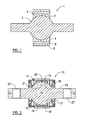
- Figure 1 illustrates a known type of spherical bearing 1 comprising a housing 2 and a ball 3 partially housed within the housing 2.
- the housing 2 comprises a race 4 having a spherical bearing surface 7, a sleeve 5 surrounding the race 4, and an elastomer 6 disposed between and bonded to the race 4 and sleeve 5.
- the race 4 and sleeve 5 are arranged coaxially about a central axis of the housing 2.
- the ball 3 is mounted within the race 4 such that the ball 3 is free to rotate but is prevented from any significant translational movement within the race 4.
- the elastomer 6 serves to absorb displacement of the ball 3 relative to the housing 2 in a radial direction, i.e. in a direction normal to the central axis of the housing 2.
- the bearing assembly 1 is able to dampen radial vibrations as well as compensate for minor misalignments in the objects to which the bearing assembly 1 is mounted.
- a problem with the bearing assembly 1 of Figure 1 is that it is ill-equipped at accommodating forces which act on the ball 3 in a direction parallel to the central axis of the housing 2, referred to hereafter as axial forces.
- Axial forces acting on the ball 3 cause the ball 3 to be displaced axially relative to the housing 2, i.e. in a direction parallel to the central axis.
- axial displacement of the ball 3 causes the race 4 to be displaced in the same direction. This displacement of the race 4 relative to the sleeve 5 creates shearing forces between the race 4 and sleeve 5.
- the bearing assembly 1 of Figure 1 is poorly-equipped at accommodating rotational forces below the threshold torque which may act on the bearing assembly 1, i.e. forces which cause the ball 3 to rotate within the housing 2. Owing to frictional forces which act between the ball 3 and race 4, rotation of the ball 3 within the race 4 encourages the race 4 to similarly rotate. This is particularly true when the bearing 1 is secured to a body by interference fit, which results in the housing 2 being radially compressed. Any rotation of the race 4 relative to the sleeve 5 will again create shearing forces.
- the bearing 1 is designed to facilitate rotation of the ball 3 within the housing 2, the bearing 1 is susceptible to failure with repeated rotation of the ball 3 below the threshold torque, due to shearing of the race:elastomer and/or sleeve:elastomer interfaces.
- the present invention provides a bearing assembly comprising a housing and a ball at least partially housed within the housing, the housing comprising a race having a concave bearing surface and receiving at least a portion of the ball, a sleeve surrounding the race, and a resilient member disposed between the race and the sleeve, wherein the surfaces of the race and sleeve adjacent the resilient member and the surfaces of the resilient member include at least one pair of a co-operating protrusion and recess.
- the at least one protrusion and recess co-operate such that the resilient member is compressed upon rotating the race relative to the sleeve.
- the race and sleeve are arranged coaxially about a central axis and the at least one protrusion and recess co-operate such that the resilient member is compressed upon rotating the race relative to the sleeve about the central axis.
- At least one co-operating protrusion and recess are annular.
- each protrusion and recess has a curved profile.
- the resilient member is of uniform thickness and the surface of the race adjacent the resilient member includes one or more protrusions and recesses and the surface of the sleeve adjacent the resilient member includes one or more co-operating recesses or protrusions.
- the surfaces of the race and sleeve adjacent the resilient member are respectively convex and concave.
- the surfaces of the race and sleeve adjacent the resilient member have different curvatures or ellipticities.
- At least one of the surfaces of the race and sleeve adjacent the resilient member is rippled.
- the surfaces of the race and sleeve adjacent the resilient member include at least one pair of a protrusion and protrusion or protrusion and recess which engage with one another upon displacement of the race relative to the sleeve so as to prevent any further displacement of the race relative to the sleeve.
- the present invention provides a bearing assembly comprising a housing and a ball at least partially housed within the housing, the housing comprising a race having a concave bearing surface and receiving at least a portion of the ball, a sleeve surrounding the race, and a resilient member disposed between the race and the sleeve, wherein the surfaces of the race and the sleeve adjacent the resilient member have different curvatures.
- one of the surfaces of the race and the sleeve adjacent the resilient member is a flat annular surface.
- the surfaces of the race and sleeve adjacent the resilient member are respectively convex and concave.
- At least one of the surfaces of the race and sleeve adjacent the resilient member has a non-spherical curvature, i.e. a non-zero ellipticity.
- the thickness of the resilient member is non-uniform.
- the resilient member is thicker at the centre of the housing than at the ends of the housing.
- the resilient member is thicker at the ends of the housing than at the centre of the housing.
- the surfaces of the race and sleeve adjacent the resilient member and the surfaces of the resilient member include at least one pair of a co-operating protrusion and recess.
- the ball and the bearing surface of the race are spherical.
- the ball includes one or more arms.
- the ball includes a bore.
- a self-lubricating liner is provided between the race and ball.
- the present invention provides a method of manufacturing a bearing assembly comprising the steps of: providing a ball; surrounding the ball with a race having a concave bearing surface; surrounding the race with a sleeve; and providing a resilient member between the race and the sleeve, wherein the surfaces of the race and sleeve adjacent the resilient member and the surfaces of the resilient member include at least one pair of a co-operating protrusion and recess.
- the step of surrounding the ball with a race comprises swaging the race onto the ball.
- the steps of surrounding the race with a sleeve and providing a resilient member between the race and sleeve comprises surrounding the race with the resilient member and swaging the sleeve over the resilient member.
- the step of providing the resilient member includes moulding an elastomer onto the race by an injection process.
- the elastomer is additionally moulded onto the sleeve.
- the bearing assembly 10 of Figure 2 comprises a housing 11 within which a ball 12 is partially housed and rotatably mounted.
- the ball 12 is preferably spherical. However, as is noted below, the shape of the ball 12 may alternatively be spheroid.
- the ball 12 of the bearing assembly 10 illustrated in Figure 2 is a complete sphere. However, only the portion of the ball 12 which engages with (i.e. contacts) the housing 11 need be spherical. Consequently the ball 12 may alternatively be an incomplete sphere or spheroid, as illustrated in Figures 3 and 5.
- the ball 12 is attached to a pair of arms 13, each arm extending on opposite sides of the ball 12 in a direction away from the housing 11.
- the ball 12 and arms 13 are preferably integral so as to form a single element.
- the arms 13 serve to mount the bearing assembly 10 to other components and may be provided, for example, with a screw thread 26 or bore 27.
- the ball 12 may instead be attached to a single arm 13, as illustrated in the embodiment of Figure 3.
- the ball 12 may have no attaching arms and instead include a bore 20 for receiving a shaft, axle or the like.
- the housing 11 comprises a race 14 having a concave bearing surface 17, a sleeve 15 arranged about the race 14 and a resilient member 16 disposed between the race 14 and the sleeve 15.
- the race 14 and sleeve 15 are arranged coaxially about a central axis of the housing 11.
- the ball 12 is mounted within the race 14 such that the ball 12 is free to rotate in at least one direction (and preferably in all directions) within the race 14.
- the shape or curvature of the bearing surface 17 of the race 14 preferably conforms to that of the ball 12.
- both the ball 12 and the bearing surface 17 of the race 14 are preferably spherical. That is to say, the bearing surface 17 and the portion of the ball 12 mounted within the race 14 have spherical curvatures.
- a non-spherical ball 12 and bearing surface 17 e.g. an oblate or prolate spheroid
- the diameter of the bearing surface 17 is preferably only slightly greater than that of the ball 12 such that rotation of the ball 12 is permitted whilst any significant translational movement of the ball 12 within the race 14 is prevented.
- the resilient member 16 preferably extends completely around the outermost surface 18 of the race 14 so as to form a collar between the race 14 and sleeve 15. Additionally, the resilient member 16 is preferably made of an elastomeric material, such as rubber. However, other means of providing resilience, such as a sealed fluid, may alternatively be used.
- the outermost surface 18 of the race 14 adjacent the resilient member 16 is convex and the innermost surface 19 of the sleeve 15 adjacent the resilient member 16 is concave.
- the surfaces 18, 19 of the race 14 and sleeve 15 adjacent the resilient member 16 have corresponding profiles. That is to say, the degrees of curvature or ellipticities of the surfaces 18, 19 are the same.
- the resilient member 16 is compressed whenever the race 14 and sleeve 15 move relative to one another in an axial direction, i.e. in a direction parallel to the central axis of housing 11. Moreover, as the race 14 and sleeve 15 are further displaced axially relative to one another, the resilient member 16 is further compressed. Consequently, the bearing assembly 10 is well-equipped at absorbing axial forces which act upon the bearing assembly, i.e. which cause the ball 12 to be displaced relative to the housing 11 in a direction towards an open end of the race 14. Moreover, the bearing assembly 10 is particularly well-suited at resisting excessive axial forces which would otherwise cause the elastomer interfaces of the spherical bearing 1 of Figure 1 to shear.
- the outermost surface 18 of the race 14 adjacent the resilient member 16 includes an annular recess or groove 21 and the innermost surface 19 of the sleeve 15 adjacent the resilient member 16 includes an annular protrusion 22.
- the recess 21 and protrusion 22 are aligned and co-operate such that the resilient member 16 is received in the recess 21 and additionally surrounds the protrusion 22.
- any motion of the race 14 relative to the resilient member 16 causes the resilient member to be compressed.
- the race 14 is rotated relative to the resilient member 16 about the same axis as that defining the annular recess 21, which in the embodiment illustrated in Figure 2 is coincident with the central axis of the housing 11.
- any motion of the sleeve 15 relative to the resilient member 16 causes the resilient member 16 to be compressed; again, with the same exception. Consequently, whenever the race 14 and sleeve 15 are displaced relative to one another, the co-operating recess 21 and protrusion 22 cause the resilient member 16 to be compressed.
- compression of the resilient member 16 by the co-operating recess 21 and protrusion 22 increases.
- the recess 21 and protrusion 22 therefore co-operate to resist forces acting upon the bearing assembly 10.
- the race 14 is displaced axially relative to the sleeve 15.
- the co-operating recess 21 and protrusion 22 then cause the resilient member 16 to be compressed so as to provide increasing resistance to axial displacement of the race 14 relative to the sleeve 15.
- the resilient member 16 and the co-operating recess 21 and protrusion 22 act to dampen axial forces and resist excessive axial forces which would otherwise cause the interfaces of the resilient member 16 with the race 14 and/or sleeve 15 to shear.
- the co-operating recess 21 and protrusion 22 additionally serve to absorb rotational forces which act between the ball 12 and the housing 11. Owing to frictional forces which act between the ball 12 and the bearing surface 17 of the race 14, the race 14 experiences a force whenever the ball 12 rotates within the race 14. This is particularly true when the bearing assembly 10 is secured to a body by interference fit. Owing to the radial compression of the housing 11 that results from an interference fit, the race 14 is generally compressed onto the ball 12. Consequently, the frictional forces between the ball 12 and race 14 can be considerable. As the ball 12 rotates within the race 14, the race 14 experiences a displacement in the direction of rotation of the ball 12.
- This displacement of the race 14 relative to the sleeve 13 creates a shearing force, which can result in the interface of the resilient member 16 with the race 14 and/or sleeve 15 failing. This is particularly true when the outermost surface 18 of the race 14 and/or the innermost surface 19 of the sleeve 15 are spherically curved.
- the bearing assembly 10 is able to accommodate not only radial and axial forces, but also rotational forces.
- the resilient member 16 is not compressed whenever the race 14 and sleeve 15 are rotated relative to one another about the axis that defines the annular recess 21. This may be addressed by having a non-annular recess and protrusion.
- more than one pair of protrusions and recesses may be provided on the interface surfaces 18, 19 of the race 14 and sleeve 15. Indeed, the surfaces 18, 19 may be provided with various forms of protrusions and co-operating recesses.
- the protrusion 22 and recess 12 may be in the form of a spiral from one open end of the bearing surface 17 to the other, a plurality of dimples and bumps, or the surfaces 18,19 may be rippled to provide a wavy profile.
- each surface 18, 19 of the race 14 and sleeve 15 may include both protrusions and recesses.
- each protrusion and recess is preferably smooth, i.e. devoid of any sharp corners. This then simplifies the manufacture and assembly of the housing 11, as described below.
- the resilient member 16 is preferably bonded to both the race 14 and sleeve 15. However, as the protrusions 22 and recesses 21 serve to retain the resilient member 16 in position, the resilient member 16 need not necessarily be bonded to either the race 14 or sleeve 15.
- the surfaces 18, 19 of the race 14 and sleeve 15 adjacent the resilient member 16 are preferably curved such that the resilient member 16 is compressed whenever the race 14 and sleeve 15 move relative to one another in an axial direction.
- the surfaces 18, 19 of the race 14 and sleeve 15 may alternatively have respective concave and convex profiles.
- the surfaces 18, 19 of the race 14 and sleeve 15 adjacent the resilient member 16 need not be curved and may equally be planar.
- the surfaces of the resilient member 16 adjacent the race 14 and sleeve 15 are free of any recesses 21 and protrusions 22.
- recesses 21 and protrusions 22 may equally be formed in the surfaces of the resilient member 16.
- FIG 3 illustrates an alternative embodiment of bearing assembly 10 in accordance with the present invention.
- the bearing assembly 10 comprises a housing 11 within which a ball 12 is housed and rotatably mounted.
- the ball 12 is only a partial sphere.
- the ball 12 is completely housed within the housing 11, rather than partially housed as in the embodiment of Figure 2.
- the ball 12 is connected to a single arm 13 which extends away from the housing 11.
- the arm 13 may be provided, for example, with a thread 26 or bore 27.
- the surfaces 18, 19 of the race 14 and sleeve 15 adjacent the resilient member 16 are planar, i.e. having no curvature. However, one or both of the surfaces 18, 19 may equally be curved. Moreover, the curvature or ellipticity of the surfaces 18, 19 may differ from one another. For example, the curvature of the outermost surface 18 of the race 14 may be sphercial (i.e. having an ellipticity of zero) whilst the curvature of the innermost surface 19 of the sleeve 15 may be spheroidal (i.e. having a non-zero ellipticity).
- the resilient member 16 is bonded to the outermost surface 18 of the race 14 and is preferably bonded to the innermost surface 19 of the sleeve 15. However, as is described below, the adjacent surfaces 18, 24 of the sleeve 15 and resilient member 16 have co-operating protrusions 22 and recesses 21 and therefore the resilient member 16 need not be bonded to the sleeve 15.
- the outermost surface 18 of the race 14 and the adjacent surface 23 of the resilient member 16 are smooth, i.e. free of any protrusions or recesses.
- the innermost surface 19 of the sleeve 15, on the other hand, includes a pair of annular protrusions 22 which co-operate with a pair of annular recesses 21 (i.e. grooves) formed on the adjacent surface 24 of the resilient member 16.
- the pairs of recesses 21 and protrusions 22 once again co-operate such that the resilient member 16 is compressed whenever the race 14 and sleeve 15 are displaced relative to one another, either as a result of axial or rotational forces.
- bearing assembly 10 is particularly advantageous when the interface that is likely to shear, upon subjecting the bearing assembly 10 to repeated or excessive axial or rotational forces, is that between the sleeve 15 and the resilient member 16.
- the housing 2 of the spherical bearing 1 of Figure 1 is generally manufactured by moulding the elastomer 6 directly onto the outermost surface of the race 4, applying an adhesive over the exposed surface of the elastomer 6 and then swaging the sleeve 5 onto the elastomer 6.
- the elastomer 6 is more securely bonded to the race 4 than to the sleeve 5. Any shearing of the bearing assembly 1 is therefore likely to occur at the interface of the sleeve 5 and elastomer 6.
- the recesses 21 and protrusions 22 formed on the adjacent surfaces 19, 24 of the sleeve 15 and resilient member 16 co-operate to prevent, or at least significantly reduce the chances of, shearing at this interface.
- recesses 21 and protrusions 22 may be additionally, or alternatively, formed on the outermost surface 18 of the race 14 and the surface 23 of resilient member 16 adjacent the race 14. Again, the recesses 21 and protrusions 22 may take on various forms, e.g. spirals, dimples/bumps, ripples.
- recesses 21 and protrusions 22 are provided on two or more adjacent surfaces 18, 19, 23, 24 of the race 14, sleeve 15 and resilient member 16.
- axial and/or rotational forces acting on the bearing assembly 10 are unlikely to result in the failure of the interfaces between the race 14 and resilient member 16 and between the sleeve 15 and resilient member 16.
- the bearing assembly 10 may suffer from a failure of the resilient member 16 itself.
- the resilient member 16 may shear through the centre or tear at the protrusions 22 and/or recesses 21. A failure of the resilient member 16 or its interfaces could potentially result in the separation of the race 14 from the sleeve 15, and therefore the separation of the ball 12 from the housing 11.
- the surfaces 18, 19 of the race 14 and sleeve 15 adjacent the resilient member 16 are preferably curved.
- the sleeve 15 preferably extends along the race 14 in a direction parallel to the central axis of the housing 11 such that inner diameter of the sleeve 15 (i.e. the diameter of the innermost surface 19 of the sleeve 15) at the ends of the housing 11 is less than the outer diameter of the race 14 (i.e. the diameter of the outermost surface 18 of the race 14) at the centre or equator of the housing 11. Consequently, should either interface or the resilient member 16 fail, the race 14 is prevented from separating from the sleeve 15 in a direction parallel to the central axis of the housing 11.
- one of the surfaces 18, 19 of the race 14 and sleeve 15 adjacent the resilient member 16 includes at least one protrusion and the other surface 18, 19 of the race 14 and sleeve 15 (referred to hereafter as the second surface) includes at least one recess and/or protrusion which engages with the protrusion of the first surface upon failure of the resilient member 16.
- the protrusion of the first surface is prevented from passing the protrusion or recess of the second surface whenever the race 14 and sleeve 15 move relative to one another. Since the protrusion of the first surface is unable to pass the protrusion/recess of the second surface, the race 14 and sleeve 15 are prevented from separating.
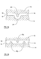
- Figures 4a and 4b illustrate possible examples of recesses 21 and protrusions 22 formed on the surfaces 18, 19 of the race 14 and sleeve 15 which engage upon failure of the resilient member 16.
- a recess 21 is formed in the surface 18 of the race 14 and a co-operating protrusion 22 is formed on the surface of the sleeve 15.
- the resilient member 16 is of uniform thickness and is free of any recesses or protrusions.
- the depth of the recess 21 and height of the protrusion 22 are each greater than the thickness of the resilient member 16. Accordingly, the protrusion 22 is prevented from escaping the recess 21 should any failure of the resilient member 16 or its interfaces with the race 14 or sleeve 15 occur.
- a pair of protrusions 22a are formed on the surface 18 of the race 14, and a single protrusion 22b is formed on the surface 19 of the sleeve 15 at a position between the two protrusions 22a of the race 14.
- the resilient member 16 in this example includes three recesses 21, each recess 21 being formed at and co-operating with a protrusion 22a, 22b.
- the height of each protrusion 22a, 22b is greater than half the normal thickness of the resilient member 16. More precisely, the total height of any pair of engaging protrusions 22a, 22b is greater than the thickness of the resilient member 16.
- the single protrusion 22b of the sleeve 15 is prevented from passing either of the protrusions 22a of the race 14 upon failure of the resilient member 16 or its interfaces.
- Figure 5 illustrates a further embodiment of a bearing assembly 10 in accordance with the present invention.
- the ball 12 of the assembly 10 is an incomplete sphere housed entirely within the housing 11 and has a bore 20 through the centre for receiving a shaft, axle or the like.
- the ball 12 may alternatively be a complete sphere (or complete/partial spheroid) and may include one or more arms attached to the ball 12.
- the outermost surface 18 of the race 14 is convex whilst the innermost surface 19 of the sleeve 15 is concave.
- the degree of curvature or ellipitcity of the innermost surface 19 of the sleeve 15 is greater than that of the outermost surface 18 of the race 14, i.e. the surface 19 of the sleeve 15 is more concave than the surface 18 of the race is convex.
- the resilient member 16 is of non-uniform thickness and is thicker at the centre or equator of the housing 11 than at the ends of the housing 11.
- the outermost surface 18 of the race 14 and innermost surface 19 of the sleeve 15 have the same degree of curvature or ellipticity; a planar surface is one having no degree of curvature or an ellipticity equal to 1.
- the resilient member 16 may be regarded as having a uniform thickness. Even when the resilient member 16 includes one or more recesses or protrusions, the thickness of the resilient member 16 at all points free from protrusion or recess is constant. In contrast, the resilient member 16 of the bearing assembly 10 of Figure 5 varies in thickness.
- the surfaces 18, 19, 23, 24 of the race 14, sleeve 15 and resilient member 16 adjacent one another are preferably free of recesses 21 and protrusions 22.
- the surfaces 18, 19, 23, 24 may nevertheless be provided with one or more pairs of co-operating protrusions and recesses.
- one or more pairs of co-operating protrusions and recesses may be formed on the outermost surface 18 of the race 14 and the adjacent surface 23 of the resilient member 16.
- This design of bearing assembly 10 is particularly advantageuous when the interface that is likely to shear, upon subjecting the bearing assembly 10 to repeated or excessive axial or rotational forces, is that between the sleeve 15 and the resilient member 16. Owing to the concave shape of the surface 19 of the sleeve 15, any axial displacement of the race 14 relative to the sleeve 15 will cause the resilient member 16 to be compressed against the surface 19 of the sleeve 15. As a result, the race 14 and sleeve 15 are prevented form separating.
- the curvature of the innermost surface 19 of the sleeve 15 is preferably non-spherical, i.e. having a non-zero ellipticity. Accordingly, any rotation of the race 14 relative to the sleeve 15 will cause the resilient member 16 to be compressed against the concave surface 19 of the sleeve 15; the only exception to this is when the race 14 and sleeve 15 rotate relative to one another about the central axis of the housing 11.
- the innermost surface 19 of the sleeve 15 is oblate, and more preferably having an oblate ellipticity (sqrt(1-(c/a) 2 ) of between 0.80 and 0.97.
- the resilient member 16 is thicker at the ends of the housing 11 that at the centre or equator of the housing 11.
- the outermost surface 18 of the race 14 is preferably curved (convex or concave) such that the race 14 and sleeve 15 are additionally prevented from separating upon failure of the race:resilient member interface. Nevertheless, the surface 18 of the race 14 may alternatively be planar, particularly when the resilient member 16 is securely bonded to the race 14 (e.g. by directly moulding the resilient member 16 onto the race).
- a lubricant or self-lubricating liner may be provided between the ball 12 and the bearing surface 17 of the race 14 to reduce friction.
- Figure 6 illustrates a further embodiment of bearing assembly 10 in which the resilient member 16 is provided as part of an insert 25.
- the insert 25 comprises an inner cylindrical wall 28 and an outer cylindrical wall 29, which surrounds and is coaxial with the inner wall 28.
- the resilient member 16 is disposed between the inner 28 and outer 29 walls of the insert 25.
- the insert 25 is inserted between the race 14 and the sleeve 15 during manufacture of the bearing assembly 10. Once inserted between the race 14 and the sleeve 15, the inner wall 28 of the insert 25 forms part of the race 14, and the outer wall 29 of the insert 25 forms part of the sleeve 15.
- the innermost surface 30 of the inner wall 28 and the outermost surface 31 of the outer wall 29 are flat annular surfaces.
- the outermost surface 18 of the race 14 and the innermost surface 19 of the sleeve are flat annular surfaces. Consequently, the insert 25 may be easily inserted between the race 14 and sleeve 15.
- the ends 32 of the inner 28 and outer 29 walls are deformable and are staked over the ends of the race 14 and the sleeve 15 after the insert 25 has been inserted such that the insert 25 is firmly retained between the race 14 and sleeve 15.
- the surfaces of the inner 28 and outer 29 walls adjacent the resilient member 16 include pairs of co-operating recesses 21 and protrusions 22. As described above in relation to the embodiments of Figures 2 to 5, recesses and protrusions may be formed on any two or more surfaces selected from the surfaces of the resilient member 16 and the surfaces of the inner 28 and outer 29 walls adjacent the resilient member 16. Additionally, or alternatively, the surfaces of the inner 28 and outer 29 walls adjacent the resilient member 16 may have different curvatures such that resilient member is of non-uniform thickness.
- the bearing assembly 10 is preferably manufactured by first swaging the race 14 onto the ball 12. Any protrusions or recesses are then machined on the outermost surface 18 of the race 14.
- the resilient member 16 is then bonded onto the outermost surface 18 of the race 14.
- the resilient member 16 is preferably an elastomer moulded directly onto the outermost surface 18 of the race 14 by injection moulding. By moulding the resilient member 16 directly on the race 14, the resilient member 16 fills any recesses and surrounds any protrusions formed on the outermost surface 18 of the race 14. Any protrusions or recesses to be formed in the outermost surface 24 of the resilient member 16 are preferably formed in the moulding processes.
- the innermost surface 19 of the sleeve 15 is then machined to include any necessary protrusions or recesses. Finally, the sleeve 15 is swaged on to the resilient member 16. Prior to swaging the sleeve 15 on to the resilient member 16, a layer of adhesive is preferably applied between the sleeve 15 and resilient member 16 such that the resilient member 16 is bonded to the sleeve 15.
- the elasticity of the bearing assembly 10 depends upon the degree by which the resilient member 16 is compressed between the race 14 and sleeve 15.
- the resilient member 16 is compressed evenly, i.e. the degree of compression is the same at all points on the resilient member 16, such that the elasticity of the bearing assembly 10 is consistent.
- the calculations required to compress the resilient member 16 evenly are much simpler.
- swaging the sleeve 15 onto the resilient member 16 to achieve even compression of the resilient member 16 is made much simpler.
- the sleeve 15 may first be positioned about the race 14 and then the resilient member 16 moulded between the race 14 and sleeve 15. In this manner, the resilient member 16 is directly bonded to both the race 14 and sleeve 15.
- the resilient member 16 may be moulded in a separate process and then pulled over the outermost surface 18 of the race 14.
- the housing 11 may be formed as a separate element and then swaged onto the ball 12.
- the bearing assembly of the present invention With the bearing assembly of the present invention, axial and rotational forces are absorbed and dampened more effectively than is possible with known spherical bearings.
- the bearing assembly is able to resist axial and rotational forces which would otherwise cause the elastomer interfaces of known spherical bearings to shear.
Abstract
Description
- THE PRESENT INVENTION relates to a bearing assembly and in particular to a spherical bearing assembly.
- Figure 1 illustrates a known type of spherical bearing 1 comprising a
housing 2 and aball 3 partially housed within thehousing 2. Thehousing 2 comprises arace 4 having a spherical bearingsurface 7, asleeve 5 surrounding therace 4, and anelastomer 6 disposed between and bonded to therace 4 andsleeve 5. Therace 4 andsleeve 5 are arranged coaxially about a central axis of thehousing 2. Theball 3 is mounted within therace 4 such that theball 3 is free to rotate but is prevented from any significant translational movement within therace 4. - The
elastomer 6 serves to absorb displacement of theball 3 relative to thehousing 2 in a radial direction, i.e. in a direction normal to the central axis of thehousing 2. As a result, the bearing assembly 1 is able to dampen radial vibrations as well as compensate for minor misalignments in the objects to which the bearing assembly 1 is mounted. - A problem with the bearing assembly 1 of Figure 1 is that it is ill-equipped at accommodating forces which act on the
ball 3 in a direction parallel to the central axis of thehousing 2, referred to hereafter as axial forces. Axial forces acting on theball 3 cause theball 3 to be displaced axially relative to thehousing 2, i.e. in a direction parallel to the central axis. Owing to the engagement of therace 4 with theball 3, axial displacement of theball 3 causes therace 4 to be displaced in the same direction. This displacement of therace 4 relative to thesleeve 5 creates shearing forces between therace 4 andsleeve 5. Consequently, repeated or excessive axial displacement of therace 4 relative to thesleeve 5 can lead to one or both of the race:elastomer and sleeve:elastomer interfaces shearing with the subsequent separation of theelastomer 6 from therace 4 and/orsleeve 5. When this occurs, theball 2 andrace 4 are free to separate from thesleeve 5 resulting in failure of the bearing 1. - There is a threshold torque between the
ball 3 andhousing 2 below which there is no resultant movement of theball 3 relative to thehousing 2. Above the threshold torque, theball 3 is caused to rotate within thehousing 2. The bearing assembly 1 of Figure 1 is poorly-equipped at accommodating rotational forces below the threshold torque which may act on the bearing assembly 1, i.e. forces which cause theball 3 to rotate within thehousing 2. Owing to frictional forces which act between theball 3 andrace 4, rotation of theball 3 within therace 4 encourages therace 4 to similarly rotate. This is particularly true when the bearing 1 is secured to a body by interference fit, which results in thehousing 2 being radially compressed. Any rotation of therace 4 relative to thesleeve 5 will again create shearing forces. Consequently, although the bearing 1 is designed to facilitate rotation of theball 3 within thehousing 2, the bearing 1 is susceptible to failure with repeated rotation of theball 3 below the threshold torque, due to shearing of the race:elastomer and/or sleeve:elastomer interfaces. - It is therefore an object of the present invention to provide a bearing assembly that overcomes one or more of the aforementioned disadvantages of the aforementioned design. In particular, it is an object of the present invention to provide a bearing assembly that is more effective at accommodating axial and/or rotational forces.
- Accordingly, in a first aspect, the present invention provides a bearing assembly comprising a housing and a ball at least partially housed within the housing, the housing comprising a race having a concave bearing surface and receiving at least a portion of the ball, a sleeve surrounding the race, and a resilient member disposed between the race and the sleeve, wherein the surfaces of the race and sleeve adjacent the resilient member and the surfaces of the resilient member include at least one pair of a co-operating protrusion and recess.
- Preferably, the at least one protrusion and recess co-operate such that the resilient member is compressed upon rotating the race relative to the sleeve.
- More preferably, the race and sleeve are arranged coaxially about a central axis and the at least one protrusion and recess co-operate such that the resilient member is compressed upon rotating the race relative to the sleeve about the central axis.
- Advantageously, at least one co-operating protrusion and recess are annular.
- Conveniently, each protrusion and recess has a curved profile.
- Preferably, the resilient member is of uniform thickness and the surface of the race adjacent the resilient member includes one or more protrusions and recesses and the surface of the sleeve adjacent the resilient member includes one or more co-operating recesses or protrusions.
- Conveniently, the surfaces of the race and sleeve adjacent the resilient member are respectively convex and concave.
- Advantageously, the surfaces of the race and sleeve adjacent the resilient member have different curvatures or ellipticities.
- Preferably, at least one of the surfaces of the race and sleeve adjacent the resilient member is rippled.
- Advantageously, the surfaces of the race and sleeve adjacent the resilient member include at least one pair of a protrusion and protrusion or protrusion and recess which engage with one another upon displacement of the race relative to the sleeve so as to prevent any further displacement of the race relative to the sleeve.
- In a second aspect, the present invention provides a bearing assembly comprising a housing and a ball at least partially housed within the housing, the housing comprising a race having a concave bearing surface and receiving at least a portion of the ball, a sleeve surrounding the race, and a resilient member disposed between the race and the sleeve, wherein the surfaces of the race and the sleeve adjacent the resilient member have different curvatures.
- Conveniently, one of the surfaces of the race and the sleeve adjacent the resilient member is a flat annular surface.
- Alternatively, the surfaces of the race and sleeve adjacent the resilient member are respectively convex and concave.
- Preferably, at least one of the surfaces of the race and sleeve adjacent the resilient member has a non-spherical curvature, i.e. a non-zero ellipticity.
- Advantageously, the thickness of the resilient member is non-uniform.
- Preferably, the resilient member is thicker at the centre of the housing than at the ends of the housing.
- Alternatively, the resilient member is thicker at the ends of the housing than at the centre of the housing.
- Conveniently, the surfaces of the race and sleeve adjacent the resilient member and the surfaces of the resilient member include at least one pair of a co-operating protrusion and recess.
- Advantageously, the ball and the bearing surface of the race are spherical.
- Conveniently, the ball includes one or more arms.
- Alternatively, the ball includes a bore.
- Advantageously a self-lubricating liner is provided between the race and ball.
- In a third aspect, the present invention provides a method of manufacturing a bearing assembly comprising the steps of: providing a ball; surrounding the ball with a race having a concave bearing surface; surrounding the race with a sleeve; and providing a resilient member between the race and the sleeve, wherein the surfaces of the race and sleeve adjacent the resilient member and the surfaces of the resilient member include at least one pair of a co-operating protrusion and recess.
- Preferably the step of surrounding the ball with a race comprises swaging the race onto the ball.
- Advantageously the steps of surrounding the race with a sleeve and providing a resilient member between the race and sleeve comprises surrounding the race with the resilient member and swaging the sleeve over the resilient member.
- Conveniently, the step of providing the resilient member includes moulding an elastomer onto the race by an injection process.
- Preferably, the elastomer is additionally moulded onto the sleeve.
- In order that the invention may be more readily understood, and so that further features thereof may be appreciated, the embodiments of the invention will now be described, by way of example, with reference to the accompanying drawings in which:
- FIGURE 1 is a cross-sectional view of a known bearing assembly;
- FIGURE 2 is a cross-sectional view of a bearing assembly in accordance with a first embodiment of the present invention;
- FIGURE 3 is a cross-sectional view of a bearing assembly in accordance with a second embodiment of the present invention;
- FIGURES 4a and 4b are exploded cross-sectional views of a region of the housing of bearing assemblies embodying the present invention;
- FIGURE 5 is a cross-sectional view of a bearing assembly in accordance with a third embodiment of the present invention; and
- FIGURE 6 is a cross-sectional view of a bearing assembly in accordance with a fourth embodiment of the present invention.
- The
bearing assembly 10 of Figure 2 comprises ahousing 11 within which aball 12 is partially housed and rotatably mounted. - The
ball 12 is preferably spherical. However, as is noted below, the shape of theball 12 may alternatively be spheroid. Theball 12 of thebearing assembly 10 illustrated in Figure 2 is a complete sphere. However, only the portion of theball 12 which engages with (i.e. contacts) thehousing 11 need be spherical. Consequently theball 12 may alternatively be an incomplete sphere or spheroid, as illustrated in Figures 3 and 5. - The
ball 12 is attached to a pair ofarms 13, each arm extending on opposite sides of theball 12 in a direction away from thehousing 11. Theball 12 andarms 13 are preferably integral so as to form a single element. Thearms 13 serve to mount thebearing assembly 10 to other components and may be provided, for example, with ascrew thread 26 or bore 27. - Rather than a pair of
arms 13, theball 12 may instead be attached to asingle arm 13, as illustrated in the embodiment of Figure 3. Alternatively, as illustrated in Figure 5, theball 12 may have no attaching arms and instead include abore 20 for receiving a shaft, axle or the like. - The
housing 11 comprises arace 14 having aconcave bearing surface 17, asleeve 15 arranged about therace 14 and aresilient member 16 disposed between therace 14 and thesleeve 15. Therace 14 andsleeve 15 are arranged coaxially about a central axis of thehousing 11. - The
ball 12 is mounted within therace 14 such that theball 12 is free to rotate in at least one direction (and preferably in all directions) within therace 14. The shape or curvature of the bearingsurface 17 of therace 14 preferably conforms to that of theball 12. Moreover, both theball 12 and the bearingsurface 17 of therace 14 are preferably spherical. That is to say, the bearingsurface 17 and the portion of theball 12 mounted within therace 14 have spherical curvatures. In employing aspherical ball 12 and bearingsurface 17, theball 12 is free to rotate in all directions within therace 14. Nevertheless, there may be instances for which anon-spherical ball 12 and bearing surface 17 (e.g. an oblate or prolate spheroid) may be desired, e.g. to inhibit rotation of theball 12 in a particular direction. - The diameter of the bearing
surface 17 is preferably only slightly greater than that of theball 12 such that rotation of theball 12 is permitted whilst any significant translational movement of theball 12 within therace 14 is prevented. - The
resilient member 16 preferably extends completely around theoutermost surface 18 of therace 14 so as to form a collar between therace 14 andsleeve 15. Additionally, theresilient member 16 is preferably made of an elastomeric material, such as rubber. However, other means of providing resilience, such as a sealed fluid, may alternatively be used. - The
outermost surface 18 of therace 14 adjacent theresilient member 16 is convex and theinnermost surface 19 of thesleeve 15 adjacent theresilient member 16 is concave. Thesurfaces race 14 andsleeve 15 adjacent theresilient member 16 have corresponding profiles. That is to say, the degrees of curvature or ellipticities of thesurfaces - Owing to the
curved surfaces race 14 andsleeve 15 adjacent theresilient member 16, theresilient member 16 is compressed whenever therace 14 andsleeve 15 move relative to one another in an axial direction, i.e. in a direction parallel to the central axis ofhousing 11. Moreover, as therace 14 andsleeve 15 are further displaced axially relative to one another, theresilient member 16 is further compressed. Consequently, the bearingassembly 10 is well-equipped at absorbing axial forces which act upon the bearing assembly, i.e. which cause theball 12 to be displaced relative to thehousing 11 in a direction towards an open end of therace 14. Moreover, the bearingassembly 10 is particularly well-suited at resisting excessive axial forces which would otherwise cause the elastomer interfaces of the spherical bearing 1 of Figure 1 to shear. - The
outermost surface 18 of therace 14 adjacent theresilient member 16 includes an annular recess orgroove 21 and theinnermost surface 19 of thesleeve 15 adjacent theresilient member 16 includes anannular protrusion 22. Therecess 21 andprotrusion 22 are aligned and co-operate such that theresilient member 16 is received in therecess 21 and additionally surrounds theprotrusion 22. - As a result of the
resilient member 16 being received by therecess 21, any motion of therace 14 relative to theresilient member 16 causes the resilient member to be compressed. The only exception to this is when therace 14 is rotated relative to theresilient member 16 about the same axis as that defining theannular recess 21, which in the embodiment illustrated in Figure 2 is coincident with the central axis of thehousing 11. Additionally, as theresilient member 16 surrounds theprotrusion 22, any motion of thesleeve 15 relative to theresilient member 16 causes theresilient member 16 to be compressed; again, with the same exception. Consequently, whenever therace 14 andsleeve 15 are displaced relative to one another, theco-operating recess 21 andprotrusion 22 cause theresilient member 16 to be compressed. Moreover, as therace 14 is further displaced relative to thesleeve 15, compression of theresilient member 16 by theco-operating recess 21 andprotrusion 22 increases. - The
recess 21 andprotrusion 22 therefore co-operate to resist forces acting upon the bearingassembly 10. For example, when axial forces act upon theball 12, therace 14 is displaced axially relative to thesleeve 15. Theco-operating recess 21 andprotrusion 22 then cause theresilient member 16 to be compressed so as to provide increasing resistance to axial displacement of therace 14 relative to thesleeve 15. In this manner, theresilient member 16 and theco-operating recess 21 andprotrusion 22 act to dampen axial forces and resist excessive axial forces which would otherwise cause the interfaces of theresilient member 16 with therace 14 and/orsleeve 15 to shear. - The
co-operating recess 21 andprotrusion 22 additionally serve to absorb rotational forces which act between theball 12 and thehousing 11. Owing to frictional forces which act between theball 12 and the bearingsurface 17 of therace 14, therace 14 experiences a force whenever theball 12 rotates within therace 14. This is particularly true when the bearingassembly 10 is secured to a body by interference fit. Owing to the radial compression of thehousing 11 that results from an interference fit, therace 14 is generally compressed onto theball 12. Consequently, the frictional forces between theball 12 andrace 14 can be considerable. As theball 12 rotates within therace 14, therace 14 experiences a displacement in the direction of rotation of theball 12. This displacement of therace 14 relative to thesleeve 13 creates a shearing force, which can result in the interface of theresilient member 16 with therace 14 and/orsleeve 15 failing. This is particularly true when theoutermost surface 18 of therace 14 and/or theinnermost surface 19 of thesleeve 15 are spherically curved. - In having a
co-operating recess 21 andprotrusion 22 on the interface surfaces 18, 19 of therace 14 andsleeve 15 adjacent theresilient member 16, theresilient member 16 is compressed whenever therace 14 is rotated relative to thesleeve 15. Accordingly, the bearingassembly 10 is able to accommodate not only radial and axial forces, but also rotational forces. - As the
recess 21 andprotrusion 22 are annular, theresilient member 16 is not compressed whenever therace 14 andsleeve 15 are rotated relative to one another about the axis that defines theannular recess 21. This may be addressed by having a non-annular recess and protrusion. Alternatively, more than one pair of protrusions and recesses may be provided on the interface surfaces 18, 19 of therace 14 andsleeve 15. Indeed, thesurfaces protrusion 22 andrecess 12 may be in the form of a spiral from one open end of the bearingsurface 17 to the other, a plurality of dimples and bumps, or thesurfaces - Whilst reference has been made to a
recess 21 in theoutermost surface 18 of therace 14 and aprotrusion 22 in theinnermost surface 19 of thesleeve 15, it will be appreciated that the same technical effect is achieved when therecess 21 is formed instead in thesurface 19 of thesleeve 15 and theprotrusion 22 is formed in thesurface 18 of therace 14. Indeed, where more than one co-operating pair of protrusions and recesses are employed, eachsurface race 14 andsleeve 15 may include both protrusions and recesses. - The profile of each protrusion and recess is preferably smooth, i.e. devoid of any sharp corners. This then simplifies the manufacture and assembly of the
housing 11, as described below. - The
resilient member 16 is preferably bonded to both therace 14 andsleeve 15. However, as theprotrusions 22 and recesses 21 serve to retain theresilient member 16 in position, theresilient member 16 need not necessarily be bonded to either therace 14 orsleeve 15. - As already noted, the
surfaces race 14 andsleeve 15 adjacent theresilient member 16 are preferably curved such that theresilient member 16 is compressed whenever therace 14 andsleeve 15 move relative to one another in an axial direction. Although reference has been made to thesurfaces race 14 andsleeve 15 having respectively convex and concave profiles, it will of course be apparent that thesurfaces protrusions 22 and recesses 21, thesurfaces race 14 andsleeve 15 adjacent theresilient member 16 need not be curved and may equally be planar. - In the embodiment of the bearing
assembly 10 described above and illustrated in Figure 2, the surfaces of theresilient member 16 adjacent therace 14 andsleeve 15 are free of anyrecesses 21 andprotrusions 22. However, as will now be demonstrated with reference to Figure 3, recesses 21 andprotrusions 22 may equally be formed in the surfaces of theresilient member 16. - Figure 3 illustrates an alternative embodiment of bearing
assembly 10 in accordance with the present invention. Once again, the bearingassembly 10 comprises ahousing 11 within which aball 12 is housed and rotatably mounted. However, unlike the embodiment of Figure 2 in which theball 12 is a complete sphere, theball 12 is only a partial sphere. Moreover, theball 12 is completely housed within thehousing 11, rather than partially housed as in the embodiment of Figure 2. - The
ball 12 is connected to asingle arm 13 which extends away from thehousing 11. Again, thearm 13 may be provided, for example, with athread 26 or bore 27. - The
surfaces race 14 andsleeve 15 adjacent theresilient member 16 are planar, i.e. having no curvature. However, one or both of thesurfaces surfaces outermost surface 18 of therace 14 may be sphercial (i.e. having an ellipticity of zero) whilst the curvature of theinnermost surface 19 of thesleeve 15 may be spheroidal (i.e. having a non-zero ellipticity). - The
resilient member 16 is bonded to theoutermost surface 18 of therace 14 and is preferably bonded to theinnermost surface 19 of thesleeve 15. However, as is described below, theadjacent surfaces sleeve 15 andresilient member 16 haveco-operating protrusions 22 and recesses 21 and therefore theresilient member 16 need not be bonded to thesleeve 15. - The
outermost surface 18 of therace 14 and theadjacent surface 23 of theresilient member 16 are smooth, i.e. free of any protrusions or recesses. Theinnermost surface 19 of thesleeve 15, on the other hand, includes a pair ofannular protrusions 22 which co-operate with a pair of annular recesses 21 (i.e. grooves) formed on theadjacent surface 24 of theresilient member 16. The pairs ofrecesses 21 andprotrusions 22 once again co-operate such that theresilient member 16 is compressed whenever therace 14 andsleeve 15 are displaced relative to one another, either as a result of axial or rotational forces. - This design of bearing
assembly 10 is particularly advantageous when the interface that is likely to shear, upon subjecting the bearingassembly 10 to repeated or excessive axial or rotational forces, is that between thesleeve 15 and theresilient member 16. - The
housing 2 of the spherical bearing 1 of Figure 1 is generally manufactured by moulding theelastomer 6 directly onto the outermost surface of therace 4, applying an adhesive over the exposed surface of theelastomer 6 and then swaging thesleeve 5 onto theelastomer 6. As a result, theelastomer 6 is more securely bonded to therace 4 than to thesleeve 5. Any shearing of the bearing assembly 1 is therefore likely to occur at the interface of thesleeve 5 andelastomer 6. With the bearingassembly 10 of the present invention, on the other hand, therecesses 21 andprotrusions 22 formed on theadjacent surfaces sleeve 15 andresilient member 16 co-operate to prevent, or at least significantly reduce the chances of, shearing at this interface. - It will, of course, be appreciated that recesses 21 and
protrusions 22 may be additionally, or alternatively, formed on theoutermost surface 18 of therace 14 and thesurface 23 ofresilient member 16 adjacent therace 14. Again, therecesses 21 andprotrusions 22 may take on various forms, e.g. spirals, dimples/bumps, ripples. - With the bearing
assembly 10 of the present invention, recesses 21 andprotrusions 22 are provided on two or moreadjacent surfaces race 14,sleeve 15 andresilient member 16. As a result, axial and/or rotational forces acting on the bearingassembly 10 are unlikely to result in the failure of the interfaces between therace 14 andresilient member 16 and between thesleeve 15 andresilient member 16. Nevertheless, there is a possibility that one or both of the interfaces may fail. Additionally, the bearingassembly 10 may suffer from a failure of theresilient member 16 itself. For example, theresilient member 16 may shear through the centre or tear at theprotrusions 22 and/or recesses 21. A failure of theresilient member 16 or its interfaces could potentially result in the separation of therace 14 from thesleeve 15, and therefore the separation of theball 12 from thehousing 11. - In order to prevent the
race 14 andsleeve 15 from separating upon failure of theresilient member 16 or its interfaces, thesurfaces race 14 andsleeve 15 adjacent theresilient member 16 are preferably curved. Moreover, thesleeve 15 preferably extends along therace 14 in a direction parallel to the central axis of thehousing 11 such that inner diameter of the sleeve 15 (i.e. the diameter of theinnermost surface 19 of the sleeve 15) at the ends of thehousing 11 is less than the outer diameter of the race 14 (i.e. the diameter of theoutermost surface 18 of the race 14) at the centre or equator of thehousing 11. Consequently, should either interface or theresilient member 16 fail, therace 14 is prevented from separating from thesleeve 15 in a direction parallel to the central axis of thehousing 11. - Alternatively, or additionally, one of the
surfaces race 14 andsleeve 15 adjacent the resilient member 16 (referred to hereafter as the first surface) includes at least one protrusion and theother surface race 14 and sleeve 15 (referred to hereafter as the second surface) includes at least one recess and/or protrusion which engages with the protrusion of the first surface upon failure of theresilient member 16. Engagement in this instance should be understood to mean that the protrusion of the first surface is prevented from passing the protrusion or recess of the second surface whenever therace 14 andsleeve 15 move relative to one another. Since the protrusion of the first surface is unable to pass the protrusion/recess of the second surface, therace 14 andsleeve 15 are prevented from separating. - Figures 4a and 4b illustrate possible examples of
recesses 21 andprotrusions 22 formed on thesurfaces race 14 andsleeve 15 which engage upon failure of theresilient member 16. - In Figure 4a, a
recess 21 is formed in thesurface 18 of therace 14 and aco-operating protrusion 22 is formed on the surface of thesleeve 15. Theresilient member 16 is of uniform thickness and is free of any recesses or protrusions. The depth of therecess 21 and height of theprotrusion 22 are each greater than the thickness of theresilient member 16. Accordingly, theprotrusion 22 is prevented from escaping therecess 21 should any failure of theresilient member 16 or its interfaces with therace 14 orsleeve 15 occur. - In Figure 4b, a pair of
protrusions 22a are formed on thesurface 18 of therace 14, and asingle protrusion 22b is formed on thesurface 19 of thesleeve 15 at a position between the twoprotrusions 22a of therace 14. Theresilient member 16 in this example includes threerecesses 21, eachrecess 21 being formed at and co-operating with aprotrusion protrusion resilient member 16. More precisely, the total height of any pair of engagingprotrusions resilient member 16. As a result, thesingle protrusion 22b of thesleeve 15 is prevented from passing either of theprotrusions 22a of therace 14 upon failure of theresilient member 16 or its interfaces. - Figure 5 illustrates a further embodiment of a bearing
assembly 10 in accordance with the present invention. In this further embodiment, theball 12 of theassembly 10 is an incomplete sphere housed entirely within thehousing 11 and has abore 20 through the centre for receiving a shaft, axle or the like. As with the embodiments of bearingassembly 10 illustrated in Figures 2 and 3, theball 12 may alternatively be a complete sphere (or complete/partial spheroid) and may include one or more arms attached to theball 12. - The
outermost surface 18 of therace 14 is convex whilst theinnermost surface 19 of thesleeve 15 is concave. The degree of curvature or ellipitcity of theinnermost surface 19 of thesleeve 15 is greater than that of theoutermost surface 18 of therace 14, i.e. thesurface 19 of thesleeve 15 is more concave than thesurface 18 of the race is convex. As a result, theresilient member 16 is of non-uniform thickness and is thicker at the centre or equator of thehousing 11 than at the ends of thehousing 11. - In the embodiments of bearing
assembly 10 illustrated in Figures 2 to 4, theoutermost surface 18 of therace 14 andinnermost surface 19 of thesleeve 15 have the same degree of curvature or ellipticity; a planar surface is one having no degree of curvature or an ellipticity equal to 1. As a result, theresilient member 16 may be regarded as having a uniform thickness. Even when theresilient member 16 includes one or more recesses or protrusions, the thickness of theresilient member 16 at all points free from protrusion or recess is constant. In contrast, theresilient member 16 of the bearingassembly 10 of Figure 5 varies in thickness. - The
surfaces race 14,sleeve 15 andresilient member 16 adjacent one another are preferably free ofrecesses 21 andprotrusions 22. However, thesurfaces outermost surface 18 of therace 14 and theadjacent surface 23 of theresilient member 16. - This design of bearing
assembly 10, like that of Figure 3, is particularly advantageuous when the interface that is likely to shear, upon subjecting the bearingassembly 10 to repeated or excessive axial or rotational forces, is that between thesleeve 15 and theresilient member 16. Owing to the concave shape of thesurface 19 of thesleeve 15, any axial displacement of therace 14 relative to thesleeve 15 will cause theresilient member 16 to be compressed against thesurface 19 of thesleeve 15. As a result, therace 14 andsleeve 15 are prevented form separating. - The curvature of the
innermost surface 19 of thesleeve 15 is preferably non-spherical, i.e. having a non-zero ellipticity. Accordingly, any rotation of therace 14 relative to thesleeve 15 will cause theresilient member 16 to be compressed against theconcave surface 19 of thesleeve 15; the only exception to this is when therace 14 andsleeve 15 rotate relative to one another about the central axis of thehousing 11. Preferably, theinnermost surface 19 of thesleeve 15 is oblate, and more preferably having an oblate ellipticity (sqrt(1-(c/a)2) of between 0.80 and 0.97. - Although reference has been made to the
innermost surface 19 of thesleeve 15 having a concave profile, it will be appreciated that the same technical effect is achieved in having asurface 19 that is convex. In this case, theresilient member 16 is thicker at the ends of thehousing 11 that at the centre or equator of thehousing 11. - The
outermost surface 18 of therace 14 is preferably curved (convex or concave) such that therace 14 andsleeve 15 are additionally prevented from separating upon failure of the race:resilient member interface. Nevertheless, thesurface 18 of therace 14 may alternatively be planar, particularly when theresilient member 16 is securely bonded to the race 14 (e.g. by directly moulding theresilient member 16 onto the race). - The specific embodiment illustrated in Figure 5 is specifically designed at preventing failure of the bearing
assembly 10 at the weaker sleeve:resilient member interface. It will of course be apparent that the profiles of thesurfaces race 14 andsleeve 15 may be reversed should the weaker interface be that between therace 14 and theresilient member 16. - In all embodiments of the bearing
assembly 10 described above, a lubricant or self-lubricating liner (not shown) may be provided between theball 12 and the bearingsurface 17 of therace 14 to reduce friction. - Figure 6 illustrates a further embodiment of bearing
assembly 10 in which theresilient member 16 is provided as part of aninsert 25. Theinsert 25 comprises an innercylindrical wall 28 and an outercylindrical wall 29, which surrounds and is coaxial with theinner wall 28. Theresilient member 16 is disposed between the inner 28 and outer 29 walls of theinsert 25. - The
insert 25 is inserted between therace 14 and thesleeve 15 during manufacture of the bearingassembly 10. Once inserted between therace 14 and thesleeve 15, theinner wall 28 of theinsert 25 forms part of therace 14, and theouter wall 29 of theinsert 25 forms part of thesleeve 15. - The
innermost surface 30 of theinner wall 28 and theoutermost surface 31 of theouter wall 29 are flat annular surfaces. Similarly, theoutermost surface 18 of therace 14 and theinnermost surface 19 of the sleeve are flat annular surfaces. Consequently, theinsert 25 may be easily inserted between therace 14 andsleeve 15. The ends 32 of the inner 28 and outer 29 walls are deformable and are staked over the ends of therace 14 and thesleeve 15 after theinsert 25 has been inserted such that theinsert 25 is firmly retained between therace 14 andsleeve 15. - The surfaces of the inner 28 and outer 29 walls adjacent the
resilient member 16 include pairs ofco-operating recesses 21 andprotrusions 22. As described above in relation to the embodiments of Figures 2 to 5, recesses and protrusions may be formed on any two or more surfaces selected from the surfaces of theresilient member 16 and the surfaces of the inner 28 and outer 29 walls adjacent theresilient member 16. Additionally, or alternatively, the surfaces of the inner 28 and outer 29 walls adjacent theresilient member 16 may have different curvatures such that resilient member is of non-uniform thickness. - A method of manufacturing the bearing assembly of Figures 2 to 5 will now be described. The bearing
assembly 10 is preferably manufactured by first swaging therace 14 onto theball 12. Any protrusions or recesses are then machined on theoutermost surface 18 of therace 14. Theresilient member 16 is then bonded onto theoutermost surface 18 of therace 14. Theresilient member 16 is preferably an elastomer moulded directly onto theoutermost surface 18 of therace 14 by injection moulding. By moulding theresilient member 16 directly on therace 14, theresilient member 16 fills any recesses and surrounds any protrusions formed on theoutermost surface 18 of therace 14. Any protrusions or recesses to be formed in theoutermost surface 24 of theresilient member 16 are preferably formed in the moulding processes. Theinnermost surface 19 of thesleeve 15 is then machined to include any necessary protrusions or recesses. Finally, thesleeve 15 is swaged on to theresilient member 16. Prior to swaging thesleeve 15 on to theresilient member 16, a layer of adhesive is preferably applied between thesleeve 15 andresilient member 16 such that theresilient member 16 is bonded to thesleeve 15. - The elasticity of the bearing
assembly 10 depends upon the degree by which theresilient member 16 is compressed between therace 14 andsleeve 15. Preferably, theresilient member 16 is compressed evenly, i.e. the degree of compression is the same at all points on theresilient member 16, such that the elasticity of the bearingassembly 10 is consistent. For those embodiments of bearingassembly 10 for which theresilient member 16 is of uniform thickness, the calculations required to compress theresilient member 16 evenly are much simpler. In particular, swaging thesleeve 15 onto theresilient member 16 to achieve even compression of theresilient member 16 is made much simpler. - Rather than moulding the
resilient member 16 onto therace 14 and then swaging thesleeve 15 onto theresilient member 16, thesleeve 15 may first be positioned about therace 14 and then theresilient member 16 moulded between therace 14 andsleeve 15. In this manner, theresilient member 16 is directly bonded to both therace 14 andsleeve 15. - It will, of course, be appreciated that other methods conventionally employed in the manufacture of bearing assemblies may alternatively or additionally be used in the manufacture of the bearing assembly of the present invention, and that the process described above is provided by way of example only. For example, the
resilient member 16 may be moulded in a separate process and then pulled over theoutermost surface 18 of therace 14. Additionally, thehousing 11 may be formed as a separate element and then swaged onto theball 12. - With the bearing assembly of the present invention, axial and rotational forces are absorbed and dampened more effectively than is possible with known spherical bearings. In particular, the bearing assembly is able to resist axial and rotational forces which would otherwise cause the elastomer interfaces of known spherical bearings to shear.
- When used in this Specification and Claims, the terms "comprises" and "comprising" and variations thereof mean that the specified features, steps or integers are included. The terms are not to be interpreted to exclude the presence of other features, steps or components.
- The features disclosed in the foregoing description, or the following Claims, or the accompanying drawings, expressed in their specific forms or in terms of a means for performing the disclosed function, or a method or process for attaining the disclosed result, as appropriate, may, separately, or in any combination of such features, be utilised for realising the invention in diverse forms thereof.
Claims (27)
- A bearing assembly comprising a housing and a ball at least partially housed within the housing, the housing comprising a race having a concave bearing surface and receiving at least a portion of the ball, a sleeve surrounding the race, and a resilient member disposed between the race and the sleeve, wherein the surfaces of the race and sleeve adjacent the resilient member and the surfaces of the resilient member include at least one pair of a co-operating protrusion and recess.
- A bearing assembly as claimed in Claim 1, wherein the at least one protrusion and recess co-operate such that at least a portion of the resilient member is compressed upon rotating the race relative to the sleeve.
- A bearing assembly as claimed in Claim 2, wherein the race and sleeve are arranged coaxially about a central axis and the at least one protrusion and recess co-operate such that at least a portion of the resilient member is compressed upon rotating the race relative to the sleeve about the central axis.
- A bearing assembly as claimed in any one of the preceding claims, wherein at least one co-operating protrusion and recess are annular.
- A bearing assembly as claimed in any one of the preceding claims, wherein each protrusion and recess has a curved profile.
- A bearing assembly as claimed in any one of the preceding claims, wherein the resilient member is of uniform thickness and the surface of the race adjacent the resilient member includes one or more protrusions and recesses and the surface of the sleeve adjacent the resilient member includes one or more co-operating recesses or protrusions.
- A bearing assembly as claimed in any one of the preceding claims, wherein the surfaces of the race and sleeve adjacent the resilient member are respectively convex and concave.
- A bearing assembly as claimed in any one of the preceding claims, wherein the surfaces of the race and sleeve adjacent the resilient member have different curvatures.
- A bearing assembly as claimed in any one of the preceding claims, wherein at least one of the surfaces of the race and sleeve adjacent the resilient member is rippled.
- A bearing assembly as claimed in any one of the preceding claims, wherein the surfaces of the race and sleeve adjacent the resilient member include at least one pair of a protrusion and protrusion or protrusion and recess which engage with one another upon displacement of the race relative to the sleeve so as to prevent any further displacement of the race relative to the sleeve.
- A bearing assembly comprising a housing and a ball at least partially housed within the housing, the housing comprising a race having a concave bearing surface and receiving at least a portion of the ball, a sleeve surrounding the race, and a resilient member disposed between the race and the sleeve, wherein the surfaces of the race and the sleeve adjacent the resilient member have different curvatures.
- A bearing assembly as claimed in Claim 11, wherein one of the surfaces of the race and the sleeve adjacent the resilient member is a flat annular surface.
- A bearing assembly as claimed in Claim 11, wherein the surfaces of the race and sleeve adjacent the resilient member are respectively convex and concave.
- A bearing assembly as claimed in any one of Claims 11 to 13, wherein at least one of the surfaces of the race and sleeve adjacent the resilient member has a non-spherical curvature.
- A bearing assembly as claimed in any one of Claims 11 to 14, wherein the thickness of the resilient member is non-uniform.
- A bearing assembly as claimed in Claim 15, wherein the resilient member is thicker at the centre of the housing than at the ends of the housing.
- A bearing assembly as claimed in Claim 15, wherein the resilient member is thicker at the ends of the housing than at the centre of the housing.
- A bearing assembly as claimed in any one of Claims 11 to 17, wherein the surfaces of the race and sleeve adjacent the resilient member and the surfaces of the resilient member include at least one pair of a co-operating protrusion and recess.
- A bearing assembly as claimed in any preceding claim, wherein the ball and the bearing surface of the race are spherical.
- A bearing assembly as claimed in any preceding claim, wherein the ball includes one or more arms.
- A bearing assembly as claimed in any one of Claims 1 to 19, wherein the ball includes a bore.
- A bearing assembly as claimed in any one of the preceding claims, wherein a self-lubricating liner is provided between the race and ball.
- A method of manufacturing a bearing assembly comprising the steps of: providing a ball; surrounding the ball with a race having a concave bearing surface; surrounding the race with a sleeve; and providing a resilient member between the race and the sleeve, wherein the surfaces of the race and sleeve adjacent the resilient member and the surfaces of the resilient member include at least one pair of a co-operating protrusion and recess.
- A method as claimed in Claim 23, wherein the step of surrounding the ball with a race comprises swaging the race onto the ball.
- A method as claimed in Claim 23 or 24, wherein the steps of surrounding the race with a sleeve and providing a resilient member between the race and sleeve comprises surrounding the race with the resilient member and swaging the sleeve over the resilient member.
- A method as claimed in any one of Claims 23 to 25, wherein the step of providing the resilient member includes moulding an elastomer onto the race by an injection process.
- A method as claimed in Claim 26, wherein the elastomer is additionally moulded onto the sleeve.
Applications Claiming Priority (1)
| Application Number | Priority Date | Filing Date | Title |
|---|---|---|---|
| GB0422182A GB2418963B (en) | 2004-10-06 | 2004-10-06 | A bearing assembly |
Publications (3)
| Publication Number | Publication Date |
|---|---|
| EP1645760A2 true EP1645760A2 (en) | 2006-04-12 |
| EP1645760A3 EP1645760A3 (en) | 2007-12-19 |
| EP1645760B1 EP1645760B1 (en) | 2009-06-03 |
Family
ID=33428164
Family Applications (1)
| Application Number | Title | Priority Date | Filing Date |
|---|---|---|---|
| EP05021644A Not-in-force EP1645760B1 (en) | 2004-10-06 | 2005-10-04 | A bearing assembly |
Country Status (7)
| Country | Link |
|---|---|
| US (1) | US7658546B2 (en) |
| EP (1) | EP1645760B1 (en) |
| JP (1) | JP2006105394A (en) |
| CN (1) | CN1757944A (en) |
| AT (1) | ATE433057T1 (en) |
| DE (1) | DE602005014719D1 (en) |
| GB (2) | GB2418963B (en) |
Cited By (5)
| Publication number | Priority date | Publication date | Assignee | Title |
|---|---|---|---|---|
| EP2284408A1 (en) * | 2009-08-10 | 2011-02-16 | Iljin Co. Ltd. | Ball joint assembly for vehicle and manufacturing method thereof |
| WO2011066641A1 (en) * | 2009-12-02 | 2011-06-09 | Flywheel Energy Systems Inc. | Compliant bearing mount |
| WO2013000517A1 (en) * | 2011-06-30 | 2013-01-03 | Schaublin Sa | Spherical plain bearing with constant torque |
| US9856910B2 (en) | 2015-11-30 | 2018-01-02 | Roller Bearing Company Of America, Inc. | Self-lubricated thrust bearing for a hinged aircraft wing |
| WO2020182392A1 (en) * | 2019-03-11 | 2020-09-17 | Zf Friedrichshafen Ag | Joint for a chassis of a vehicle, structural component for a chassis of a vehicle having such a joint, and method for producing such a structural component |
Families Citing this family (29)
| Publication number | Priority date | Publication date | Assignee | Title |
|---|---|---|---|---|
| DE102009026739A1 (en) * | 2009-06-04 | 2010-12-09 | Zf Friedrichshafen Ag | Joint and / or bearing arrangement with an elastic intermediate layer |
| CN103025454B (en) * | 2010-05-28 | 2015-07-29 | Skf公司 | Comprise the assembly of radial transition joint and the corresponding method in conjunction with two parts |
| KR101312710B1 (en) * | 2010-06-14 | 2013-10-01 | 주식회사 일진 | Mono axia damping joint for assembling automotive chassis parts |
| DE102010042118A1 (en) * | 2010-10-07 | 2012-04-12 | Robert Bosch Gmbh | Slide bearing, method for producing a plain bearing and use of a sliding bearing |
| CN103403373A (en) * | 2010-11-16 | 2013-11-20 | 美国滚柱轴承公司 | Spherical plain bearing and method for assembling the same |
| US9316257B2 (en) | 2011-04-01 | 2016-04-19 | Roller Bearing Company Of America, Inc. | Spherical bearing with sealing member member |
| US9958011B2 (en) | 2011-04-01 | 2018-05-01 | Roller Bearing Company Of America, Inc. | Bearing assembly having surface protrusions and a seal |
| US8783953B2 (en) | 2011-07-21 | 2014-07-22 | Roller Bearing Company Of America, Inc. | Low friction seal for bearings |
| DE102012207527B4 (en) * | 2012-05-07 | 2022-12-29 | Zf Friedrichshafen Ag | Sleeve joint for a vehicle |
| US9010679B2 (en) * | 2012-06-26 | 2015-04-21 | Bell Helicopter Textron Inc. | Hybrid spherical and thrust bearing |
| US9840325B2 (en) * | 2012-06-26 | 2017-12-12 | Bell Helicopter Textron Inc. | Dual series pitch link bearing |
| CN103161820A (en) * | 2013-04-07 | 2013-06-19 | 赵丰 | Torque rod assembly with rotary type joint |
| JP6267456B2 (en) * | 2013-08-23 | 2018-01-24 | 東洋ゴム工業株式会社 | Method for manufacturing elastic bush for traveling vehicle |
| US9562567B2 (en) | 2014-02-07 | 2017-02-07 | Roller Bearing Company Of America, Inc. | Spherical bearing with axially compressed annular seal |
| US9371861B2 (en) | 2014-02-11 | 2016-06-21 | Roller Bearing Company Of America, Inc. | Swaged bearing assembly with a flange mounted thereon |
| US9353792B2 (en) | 2014-02-19 | 2016-05-31 | Google Inc. | Biased compound radial plain bearing for increased life in oscillating pivot motion |
| US9764831B2 (en) * | 2014-03-10 | 2017-09-19 | Bell Helicopter Textron Inc. | Articulated main rotor hub with inwardly CF bearing and 3% flapping hinge offset |
| CN104314993B (en) * | 2014-06-22 | 2016-10-26 | 廖应良 | Self-aligning bearing seat assembly used by a kind of rake |
| CN104482054A (en) * | 2014-11-14 | 2015-04-01 | 东方电气集团东方汽轮机有限公司 | Bearing of large high-speed rotary machine |
| JP2016200251A (en) * | 2015-04-14 | 2016-12-01 | 日本電産テクノモータ株式会社 | Bearing device and motor |
| CN106487155A (en) * | 2015-08-31 | 2017-03-08 | 德昌电机(深圳)有限公司 | Liquid pump, motor and its shaft sleeve unit |
| DE102016220438A1 (en) * | 2016-10-19 | 2018-04-19 | Zf Friedrichshafen Ag | Sleeve joint, especially for a vehicle |
| DE102016225127A1 (en) * | 2016-12-15 | 2018-06-21 | Zf Friedrichshafen Ag | Joint for a vehicle and method of manufacturing such a joint |
| DE102017111668B4 (en) * | 2017-05-29 | 2021-06-02 | Benteler Automobiltechnik Gmbh | Bearing bush |
| AU2018297244A1 (en) * | 2017-07-05 | 2020-01-23 | Schlumberger Technology B.V. | Spherical elastomeric mounts |
| CN107339343A (en) * | 2017-08-27 | 2017-11-10 | 湖南运达机电科技股份有限公司 | A kind of automobile brake shoe Floating cam drum brake |
| US10604244B2 (en) * | 2017-11-16 | 2020-03-31 | Aktiebolaget Skf | Combination elastomeric and ellipsoidal plain bearing |
| US10371200B2 (en) * | 2017-12-06 | 2019-08-06 | Aktiebolaget Skf | Combination elastomeric and cylindrical plain bearing |
| CN109048871A (en) * | 2018-10-23 | 2018-12-21 | 国运科技(大连)有限公司 | A kind of manipulator |
Citations (2)
| Publication number | Priority date | Publication date | Assignee | Title |
|---|---|---|---|---|
| GB2106173A (en) | 1981-09-22 | 1983-04-07 | Automotive Products Plc | Ball and socket joints |
| DE10124843A1 (en) | 2001-05-22 | 2002-11-28 | Ina Schaeffler Kg | Slide bearing has housing with full-length opening and cylindrical slide bush fitted in interspace between inner housing part and wall and axially deformed to fit into cavities in between |
Family Cites Families (30)
| Publication number | Priority date | Publication date | Assignee | Title |
|---|---|---|---|---|
| US2488775A (en) * | 1943-07-24 | 1949-11-22 | Heim Company | Bearing |
| GB600265A (en) * | 1944-10-16 | 1948-04-05 | Thompson Prod Inc | Improvements in or relating to ball and socket joints |
| US2804679A (en) * | 1954-08-23 | 1957-09-03 | Southwest Products Co | Method of making bearings and rod end bearings |
| US2856203A (en) * | 1954-09-29 | 1958-10-14 | American Steel Foundries | Fifth wheel bracket |
| US3162930A (en) * | 1961-04-11 | 1964-12-29 | Fafnir Bearing Co | Method of making antifiriction bearings |
| US3193910A (en) * | 1962-10-01 | 1965-07-13 | Southwest Products Co | Method of making bearings |
| US3583775A (en) * | 1968-06-20 | 1971-06-08 | Textron Inc | Spherical bearing and method of making the same |
| US3754802A (en) * | 1972-01-25 | 1973-08-28 | Mpb Corp | Self-aligning bearing assembly |
| JPS5137365A (en) * | 1974-09-27 | 1976-03-29 | Toshio Hata | |
| JPS5224658A (en) * | 1975-08-18 | 1977-02-24 | Saitama Kiki Kk | Non-oil feeding bearing of ball joint |
| US4034996A (en) * | 1975-10-08 | 1977-07-12 | Saitamakiki Co., Ltd. | Ball joint for torque rod |
| DE2630205A1 (en) * | 1976-07-05 | 1978-01-19 | Hurth Masch Zahnrad Carl | TILT PINS FOR JOINTS, IN PARTICULAR CARDAN JOINTS OR DGL. |
| GB2103757A (en) * | 1981-08-11 | 1983-02-23 | Btr Plc | Improvements in bushes |
| US4844627A (en) * | 1983-07-25 | 1989-07-04 | Mcdonnell Douglas Corporation | Interference fit bearings |
| DE3933163A1 (en) * | 1988-10-27 | 1990-05-03 | Toyoda Gosei Kk | CYLINDRICAL DAMPING BUSH |
| US5033722A (en) * | 1989-08-21 | 1991-07-23 | Caterpillar Inc. | Resilient mount assembly |
| DE4138609C2 (en) * | 1991-11-25 | 1997-07-17 | Lemfoerder Metallwaren Ag | Ball sleeve central joint |
| JPH05199184A (en) | 1992-01-20 | 1993-08-06 | Fujitsu Ltd | Light amplifier repeater |
| US5178482A (en) * | 1992-01-22 | 1993-01-12 | Trw Inc. | Ball joint |
| GB2263948B (en) * | 1992-01-31 | 1996-03-06 | Minebea Co Ltd | Spherical bearing |
| DE4216559C2 (en) * | 1992-05-20 | 1995-05-24 | Freudenberg Carl Fa | Swivel bearing |
| DE4240099C1 (en) * | 1992-11-28 | 1994-05-19 | Schaeffler Waelzlager Kg | Ball or roller shaft bearing assembly - has outer races secured in bore by common elastic ring of constant cross=section |
| US5697723A (en) * | 1995-12-12 | 1997-12-16 | Trw Inc. | Joint assembly |
| JPH09177778A (en) * | 1995-12-27 | 1997-07-11 | Minebea Co Ltd | Spherical sliding bearing |
| US5902050A (en) * | 1996-05-31 | 1999-05-11 | Lord Corporation | Spherical elastomeric bearing assembly |
| DE19736106B4 (en) * | 1997-08-20 | 2006-03-23 | Ina-Schaeffler Kg | Storage of a shift lever for an external circuit of a motor vehicle transmission |
| DE19830593C1 (en) * | 1998-07-09 | 2000-02-17 | Sachsenring Entwicklungsgesell | Ball joint and method for its production |
| JP2002276652A (en) * | 2001-03-19 | 2002-09-25 | Kawasaki Steel Corp | Cylindrical roller bearing |
| DE10150189A1 (en) * | 2001-10-12 | 2003-04-17 | Zf Lemfoerder Metallwaren Ag | Vibration damping rubber bearing has elastomer annular body fitted outwardly radially to inner wall of outer shell |
| JP2003247540A (en) | 2002-02-26 | 2003-09-05 | Minebea Co Ltd | Rolling bearing and rod end bearing |
-
2004
- 2004-10-06 GB GB0422182A patent/GB2418963B/en not_active Withdrawn - After Issue
- 2004-10-06 GB GB0620736A patent/GB2428752B/en not_active Withdrawn - After Issue
-
2005
- 2005-09-30 JP JP2005287790A patent/JP2006105394A/en not_active Withdrawn
- 2005-10-04 US US11/243,414 patent/US7658546B2/en not_active Expired - Fee Related
- 2005-10-04 EP EP05021644A patent/EP1645760B1/en not_active Not-in-force
- 2005-10-04 AT AT05021644T patent/ATE433057T1/en not_active IP Right Cessation
- 2005-10-04 DE DE602005014719T patent/DE602005014719D1/en active Active
- 2005-10-08 CN CNA2005101082616A patent/CN1757944A/en active Pending
Patent Citations (2)
| Publication number | Priority date | Publication date | Assignee | Title |
|---|---|---|---|---|
| GB2106173A (en) | 1981-09-22 | 1983-04-07 | Automotive Products Plc | Ball and socket joints |
| DE10124843A1 (en) | 2001-05-22 | 2002-11-28 | Ina Schaeffler Kg | Slide bearing has housing with full-length opening and cylindrical slide bush fitted in interspace between inner housing part and wall and axially deformed to fit into cavities in between |
Cited By (7)
| Publication number | Priority date | Publication date | Assignee | Title |
|---|---|---|---|---|
| EP2284408A1 (en) * | 2009-08-10 | 2011-02-16 | Iljin Co. Ltd. | Ball joint assembly for vehicle and manufacturing method thereof |
| WO2011066641A1 (en) * | 2009-12-02 | 2011-06-09 | Flywheel Energy Systems Inc. | Compliant bearing mount |
| GB2488477A (en) * | 2009-12-02 | 2012-08-29 | Flywheel Energy Systems Inc | Compliant bearing mounting |
| WO2013000517A1 (en) * | 2011-06-30 | 2013-01-03 | Schaublin Sa | Spherical plain bearing with constant torque |
| CN103842669A (en) * | 2011-06-30 | 2014-06-04 | 肖柏林股份有限公司 | Spherical plain bearing with constant torque |
| US9856910B2 (en) | 2015-11-30 | 2018-01-02 | Roller Bearing Company Of America, Inc. | Self-lubricated thrust bearing for a hinged aircraft wing |
| WO2020182392A1 (en) * | 2019-03-11 | 2020-09-17 | Zf Friedrichshafen Ag | Joint for a chassis of a vehicle, structural component for a chassis of a vehicle having such a joint, and method for producing such a structural component |
Also Published As
| Publication number | Publication date |
|---|---|
| GB0620736D0 (en) | 2006-11-29 |
| US7658546B2 (en) | 2010-02-09 |
| ATE433057T1 (en) | 2009-06-15 |
| GB0422182D0 (en) | 2004-11-03 |
| JP2006105394A (en) | 2006-04-20 |
| GB2428752A (en) | 2007-02-07 |
| CN1757944A (en) | 2006-04-12 |
| GB2418963B (en) | 2007-04-04 |
| US20060098908A1 (en) | 2006-05-11 |
| GB2428752B (en) | 2007-03-14 |
| GB2418963A (en) | 2006-04-12 |
| EP1645760A3 (en) | 2007-12-19 |
| DE602005014719D1 (en) | 2009-07-16 |
| EP1645760B1 (en) | 2009-06-03 |
Similar Documents
| Publication | Publication Date | Title |
|---|---|---|
| US7658546B2 (en) | Bearing assembly | |
| US9709089B2 (en) | Combination spherical and laminated bearing assembly | |
| EP3464915B1 (en) | Socket assembly and method of making a socket assembly | |
| WO2006018684A1 (en) | A bush | |
| CN109312776B (en) | Socket assembly and method of manufacturing socket assembly | |
| US4430016A (en) | Ball joint | |
| KR100891048B1 (en) | Ball joint | |
| CN107250578A (en) | Globe joint component | |
| CN110030260B (en) | Combined elastomer and cylindrical sliding bearing | |
| US6454484B1 (en) | Compliant pivot socket for automotive steering | |
| US6413003B1 (en) | Compliant pivot socket for automotive steering | |
| EP3552839B1 (en) | Assembling structure for tire wheel, brake rotor, and hub | |
| US4913411A (en) | High-capacity elastomeric combination journal-thrust bearing | |
| CN109072968A (en) | Shield for slot component | |
| JPH083330B2 (en) | Ball joint for automobile transmission | |
| CN101400909B (en) | Cage for ball bearing | |
| JPH083331B2 (en) | Ball joint for automobile transmission linkage | |
| WO2019217768A1 (en) | Compression loaded ball socket assembly | |
| KR102482125B1 (en) | Device for reducing hysteresis of spring | |
| US11162539B2 (en) | Constant velocity joint and assembly method therefor | |
| US10584737B2 (en) | Compression loaded ball socket assembly | |
| US20060293107A1 (en) | U-joint seal spring system | |
| CN211288509U (en) | Protective sleeve | |
| JPS6341260Y2 (en) |
Legal Events
| Date | Code | Title | Description |
|---|---|---|---|
| PUAI | Public reference made under article 153(3) epc to a published international application that has entered the european phase |
Free format text: ORIGINAL CODE: 0009012 |
|
| AK | Designated contracting states |
Kind code of ref document: A2 Designated state(s): AT BE BG CH CY CZ DE DK EE ES FI FR GB GR HU IE IS IT LI LT LU LV MC NL PL PT RO SE SI SK TR |
|
| AX | Request for extension of the european patent |
Extension state: AL BA HR MK YU |
|
| PUAL | Search report despatched |
Free format text: ORIGINAL CODE: 0009013 |
|
| AK | Designated contracting states |
Kind code of ref document: A3 Designated state(s): AT BE BG CH CY CZ DE DK EE ES FI FR GB GR HU IE IS IT LI LT LU LV MC NL PL PT RO SE SI SK TR |
|
| AX | Request for extension of the european patent |
Extension state: AL BA HR MK YU |
|
| 17P | Request for examination filed |
Effective date: 20080519 |
|
| AKX | Designation fees paid |
Designated state(s): AT BE BG CH CY CZ DE DK EE ES FI FR GB GR HU IE IS IT LI LT LU LV MC NL PL PT RO SE SI SK TR |
|
| 17Q | First examination report despatched |
Effective date: 20090114 |
|
| GRAP | Despatch of communication of intention to grant a patent |
Free format text: ORIGINAL CODE: EPIDOSNIGR1 |
|
| GRAS | Grant fee paid |
Free format text: ORIGINAL CODE: EPIDOSNIGR3 |
|
| GRAA | (expected) grant |
Free format text: ORIGINAL CODE: 0009210 |
|
| AK | Designated contracting states |
Kind code of ref document: B1 Designated state(s): AT BE BG CH CY CZ DE DK EE ES FI FR GB GR HU IE IS IT LI LT LU LV MC NL PL PT RO SE SI SK TR |
|
| REG | Reference to a national code |
Ref country code: GB Ref legal event code: FG4D |
|
| REG | Reference to a national code |
Ref country code: CH Ref legal event code: EP |
|
| REG | Reference to a national code |
Ref country code: IE Ref legal event code: FG4D |
|
| REF | Corresponds to: |
Ref document number: 602005014719 Country of ref document: DE Date of ref document: 20090716 Kind code of ref document: P |
|
| PG25 | Lapsed in a contracting state [announced via postgrant information from national office to epo] |
Ref country code: FI Free format text: LAPSE BECAUSE OF FAILURE TO SUBMIT A TRANSLATION OF THE DESCRIPTION OR TO PAY THE FEE WITHIN THE PRESCRIBED TIME-LIMIT Effective date: 20090603 Ref country code: LT Free format text: LAPSE BECAUSE OF FAILURE TO SUBMIT A TRANSLATION OF THE DESCRIPTION OR TO PAY THE FEE WITHIN THE PRESCRIBED TIME-LIMIT Effective date: 20090603 Ref country code: AT Free format text: LAPSE BECAUSE OF FAILURE TO SUBMIT A TRANSLATION OF THE DESCRIPTION OR TO PAY THE FEE WITHIN THE PRESCRIBED TIME-LIMIT Effective date: 20090603 |
|
| NLV1 | Nl: lapsed or annulled due to failure to fulfill the requirements of art. 29p and 29m of the patents act | ||
| PG25 | Lapsed in a contracting state [announced via postgrant information from national office to epo] |
Ref country code: LV Free format text: LAPSE BECAUSE OF FAILURE TO SUBMIT A TRANSLATION OF THE DESCRIPTION OR TO PAY THE FEE WITHIN THE PRESCRIBED TIME-LIMIT Effective date: 20090603 Ref country code: PL Free format text: LAPSE BECAUSE OF FAILURE TO SUBMIT A TRANSLATION OF THE DESCRIPTION OR TO PAY THE FEE WITHIN THE PRESCRIBED TIME-LIMIT Effective date: 20090603 Ref country code: SE Free format text: LAPSE BECAUSE OF FAILURE TO SUBMIT A TRANSLATION OF THE DESCRIPTION OR TO PAY THE FEE WITHIN THE PRESCRIBED TIME-LIMIT Effective date: 20090903 Ref country code: SI Free format text: LAPSE BECAUSE OF FAILURE TO SUBMIT A TRANSLATION OF THE DESCRIPTION OR TO PAY THE FEE WITHIN THE PRESCRIBED TIME-LIMIT Effective date: 20090603 Ref country code: NL Free format text: LAPSE BECAUSE OF FAILURE TO SUBMIT A TRANSLATION OF THE DESCRIPTION OR TO PAY THE FEE WITHIN THE PRESCRIBED TIME-LIMIT Effective date: 20090603 |
|
| PG25 | Lapsed in a contracting state [announced via postgrant information from national office to epo] |
Ref country code: EE Free format text: LAPSE BECAUSE OF FAILURE TO SUBMIT A TRANSLATION OF THE DESCRIPTION OR TO PAY THE FEE WITHIN THE PRESCRIBED TIME-LIMIT Effective date: 20090603 Ref country code: IS Free format text: LAPSE BECAUSE OF FAILURE TO SUBMIT A TRANSLATION OF THE DESCRIPTION OR TO PAY THE FEE WITHIN THE PRESCRIBED TIME-LIMIT Effective date: 20091003 Ref country code: ES Free format text: LAPSE BECAUSE OF FAILURE TO SUBMIT A TRANSLATION OF THE DESCRIPTION OR TO PAY THE FEE WITHIN THE PRESCRIBED TIME-LIMIT Effective date: 20090914 Ref country code: CZ Free format text: LAPSE BECAUSE OF FAILURE TO SUBMIT A TRANSLATION OF THE DESCRIPTION OR TO PAY THE FEE WITHIN THE PRESCRIBED TIME-LIMIT Effective date: 20090603 Ref country code: RO Free format text: LAPSE BECAUSE OF FAILURE TO SUBMIT A TRANSLATION OF THE DESCRIPTION OR TO PAY THE FEE WITHIN THE PRESCRIBED TIME-LIMIT Effective date: 20090603 |
|
| PG25 | Lapsed in a contracting state [announced via postgrant information from national office to epo] |
Ref country code: BE Free format text: LAPSE BECAUSE OF FAILURE TO SUBMIT A TRANSLATION OF THE DESCRIPTION OR TO PAY THE FEE WITHIN THE PRESCRIBED TIME-LIMIT Effective date: 20090603 Ref country code: SK Free format text: LAPSE BECAUSE OF FAILURE TO SUBMIT A TRANSLATION OF THE DESCRIPTION OR TO PAY THE FEE WITHIN THE PRESCRIBED TIME-LIMIT Effective date: 20090603 |
|
| PG25 | Lapsed in a contracting state [announced via postgrant information from national office to epo] |
Ref country code: BG Free format text: LAPSE BECAUSE OF FAILURE TO SUBMIT A TRANSLATION OF THE DESCRIPTION OR TO PAY THE FEE WITHIN THE PRESCRIBED TIME-LIMIT Effective date: 20090903 Ref country code: PT Free format text: LAPSE BECAUSE OF FAILURE TO SUBMIT A TRANSLATION OF THE DESCRIPTION OR TO PAY THE FEE WITHIN THE PRESCRIBED TIME-LIMIT Effective date: 20091003 |
|
| PLBE | No opposition filed within time limit |
Free format text: ORIGINAL CODE: 0009261 |
|
| STAA | Information on the status of an ep patent application or granted ep patent |
Free format text: STATUS: NO OPPOSITION FILED WITHIN TIME LIMIT |
|
| PG25 | Lapsed in a contracting state [announced via postgrant information from national office to epo] |
Ref country code: DK Free format text: LAPSE BECAUSE OF FAILURE TO SUBMIT A TRANSLATION OF THE DESCRIPTION OR TO PAY THE FEE WITHIN THE PRESCRIBED TIME-LIMIT Effective date: 20090603 |
|
| 26N | No opposition filed |
Effective date: 20100304 |
|
| PG25 | Lapsed in a contracting state [announced via postgrant information from national office to epo] |
Ref country code: MC Free format text: LAPSE BECAUSE OF NON-PAYMENT OF DUE FEES Effective date: 20091031 |
|
| REG | Reference to a national code |
Ref country code: CH Ref legal event code: PL |
|
| REG | Reference to a national code |
Ref country code: IE Ref legal event code: MM4A |
|
| PG25 | Lapsed in a contracting state [announced via postgrant information from national office to epo] |
Ref country code: CH Free format text: LAPSE BECAUSE OF NON-PAYMENT OF DUE FEES Effective date: 20091031 Ref country code: GR Free format text: LAPSE BECAUSE OF FAILURE TO SUBMIT A TRANSLATION OF THE DESCRIPTION OR TO PAY THE FEE WITHIN THE PRESCRIBED TIME-LIMIT Effective date: 20090904 Ref country code: IE Free format text: LAPSE BECAUSE OF NON-PAYMENT OF DUE FEES Effective date: 20091004 Ref country code: LI Free format text: LAPSE BECAUSE OF NON-PAYMENT OF DUE FEES Effective date: 20091031 |
|
| PG25 | Lapsed in a contracting state [announced via postgrant information from national office to epo] |
Ref country code: IT Free format text: LAPSE BECAUSE OF FAILURE TO SUBMIT A TRANSLATION OF THE DESCRIPTION OR TO PAY THE FEE WITHIN THE PRESCRIBED TIME-LIMIT Effective date: 20090603 |
|
| PG25 | Lapsed in a contracting state [announced via postgrant information from national office to epo] |
Ref country code: LU Free format text: LAPSE BECAUSE OF NON-PAYMENT OF DUE FEES Effective date: 20091004 |
|
| PG25 | Lapsed in a contracting state [announced via postgrant information from national office to epo] |
Ref country code: HU Free format text: LAPSE BECAUSE OF FAILURE TO SUBMIT A TRANSLATION OF THE DESCRIPTION OR TO PAY THE FEE WITHIN THE PRESCRIBED TIME-LIMIT Effective date: 20091204 |
|
| PG25 | Lapsed in a contracting state [announced via postgrant information from national office to epo] |
Ref country code: TR Free format text: LAPSE BECAUSE OF FAILURE TO SUBMIT A TRANSLATION OF THE DESCRIPTION OR TO PAY THE FEE WITHIN THE PRESCRIBED TIME-LIMIT Effective date: 20090603 |
|
| PG25 | Lapsed in a contracting state [announced via postgrant information from national office to epo] |
Ref country code: CY Free format text: LAPSE BECAUSE OF FAILURE TO SUBMIT A TRANSLATION OF THE DESCRIPTION OR TO PAY THE FEE WITHIN THE PRESCRIBED TIME-LIMIT Effective date: 20090603 |
|
| REG | Reference to a national code |
Ref country code: FR Ref legal event code: PLFP Year of fee payment: 12 |
|
| REG | Reference to a national code |
Ref country code: FR Ref legal event code: PLFP Year of fee payment: 13 |
|
| REG | Reference to a national code |
Ref country code: DE Ref legal event code: R082 Ref document number: 602005014719 Country of ref document: DE Representative=s name: BOEHMERT & BOEHMERT ANWALTSPARTNERSCHAFT MBB -, DE Ref country code: DE Ref legal event code: R081 Ref document number: 602005014719 Country of ref document: DE Owner name: MINEBEA MITSUMI INC., JP Free format text: FORMER OWNER: MINEBEA CO., LTD., NAGANO, JP |
|
| PGFP | Annual fee paid to national office [announced via postgrant information from national office to epo] |
Ref country code: DE Payment date: 20181031 Year of fee payment: 14 |
|
| PGFP | Annual fee paid to national office [announced via postgrant information from national office to epo] |
Ref country code: FR Payment date: 20181122 Year of fee payment: 14 Ref country code: GB Payment date: 20181126 Year of fee payment: 14 |
|
| REG | Reference to a national code |
Ref country code: DE Ref legal event code: R119 Ref document number: 602005014719 Country of ref document: DE |
|
| PG25 | Lapsed in a contracting state [announced via postgrant information from national office to epo] |
Ref country code: DE Free format text: LAPSE BECAUSE OF NON-PAYMENT OF DUE FEES Effective date: 20200501 |
|
| GBPC | Gb: european patent ceased through non-payment of renewal fee |
Effective date: 20191004 |
|
| PG25 | Lapsed in a contracting state [announced via postgrant information from national office to epo] |
Ref country code: FR Free format text: LAPSE BECAUSE OF NON-PAYMENT OF DUE FEES Effective date: 20191031 Ref country code: GB Free format text: LAPSE BECAUSE OF NON-PAYMENT OF DUE FEES Effective date: 20191004 |