US5902050A - Spherical elastomeric bearing assembly - Google Patents
Spherical elastomeric bearing assembly Download PDFInfo
- Publication number
- US5902050A US5902050A US08/657,851 US65785196A US5902050A US 5902050 A US5902050 A US 5902050A US 65785196 A US65785196 A US 65785196A US 5902050 A US5902050 A US 5902050A
- Authority
- US
- United States
- Prior art keywords
- generally cylindrical
- elastomeric member
- external surface
- spherical
- generally
- Prior art date
- Legal status (The legal status is an assumption and is not a legal conclusion. Google has not performed a legal analysis and makes no representation as to the accuracy of the status listed.)
- Expired - Fee Related
Links
Images


Classifications
-
- F—MECHANICAL ENGINEERING; LIGHTING; HEATING; WEAPONS; BLASTING
- F16—ENGINEERING ELEMENTS AND UNITS; GENERAL MEASURES FOR PRODUCING AND MAINTAINING EFFECTIVE FUNCTIONING OF MACHINES OR INSTALLATIONS; THERMAL INSULATION IN GENERAL
- F16C—SHAFTS; FLEXIBLE SHAFTS; ELEMENTS OR CRANKSHAFT MECHANISMS; ROTARY BODIES OTHER THAN GEARING ELEMENTS; BEARINGS
- F16C33/00—Parts of bearings; Special methods for making bearings or parts thereof
- F16C33/02—Parts of sliding-contact bearings
- F16C33/04—Brasses; Bushes; Linings
- F16C33/20—Sliding surface consisting mainly of plastics
-
- F—MECHANICAL ENGINEERING; LIGHTING; HEATING; WEAPONS; BLASTING
- F16—ENGINEERING ELEMENTS AND UNITS; GENERAL MEASURES FOR PRODUCING AND MAINTAINING EFFECTIVE FUNCTIONING OF MACHINES OR INSTALLATIONS; THERMAL INSULATION IN GENERAL
- F16C—SHAFTS; FLEXIBLE SHAFTS; ELEMENTS OR CRANKSHAFT MECHANISMS; ROTARY BODIES OTHER THAN GEARING ELEMENTS; BEARINGS
- F16C11/00—Pivots; Pivotal connections
- F16C11/04—Pivotal connections
- F16C11/06—Ball-joints; Other joints having more than one degree of angular freedom, i.e. universal joints
- F16C11/0614—Ball-joints; Other joints having more than one degree of angular freedom, i.e. universal joints the female part of the joint being open on two sides
-
- F—MECHANICAL ENGINEERING; LIGHTING; HEATING; WEAPONS; BLASTING
- F16—ENGINEERING ELEMENTS AND UNITS; GENERAL MEASURES FOR PRODUCING AND MAINTAINING EFFECTIVE FUNCTIONING OF MACHINES OR INSTALLATIONS; THERMAL INSULATION IN GENERAL
- F16C—SHAFTS; FLEXIBLE SHAFTS; ELEMENTS OR CRANKSHAFT MECHANISMS; ROTARY BODIES OTHER THAN GEARING ELEMENTS; BEARINGS
- F16C11/00—Pivots; Pivotal connections
- F16C11/04—Pivotal connections
- F16C11/06—Ball-joints; Other joints having more than one degree of angular freedom, i.e. universal joints
- F16C11/08—Ball-joints; Other joints having more than one degree of angular freedom, i.e. universal joints with resilient bearings
- F16C11/083—Ball-joints; Other joints having more than one degree of angular freedom, i.e. universal joints with resilient bearings by means of parts of rubber or like materials
-
- F—MECHANICAL ENGINEERING; LIGHTING; HEATING; WEAPONS; BLASTING
- F16—ENGINEERING ELEMENTS AND UNITS; GENERAL MEASURES FOR PRODUCING AND MAINTAINING EFFECTIVE FUNCTIONING OF MACHINES OR INSTALLATIONS; THERMAL INSULATION IN GENERAL
- F16C—SHAFTS; FLEXIBLE SHAFTS; ELEMENTS OR CRANKSHAFT MECHANISMS; ROTARY BODIES OTHER THAN GEARING ELEMENTS; BEARINGS
- F16C27/00—Elastic or yielding bearings or bearing supports, for exclusively rotary movement
- F16C27/06—Elastic or yielding bearings or bearing supports, for exclusively rotary movement by means of parts of rubber or like materials
- F16C27/063—Sliding contact bearings
-
- F—MECHANICAL ENGINEERING; LIGHTING; HEATING; WEAPONS; BLASTING
- F16—ENGINEERING ELEMENTS AND UNITS; GENERAL MEASURES FOR PRODUCING AND MAINTAINING EFFECTIVE FUNCTIONING OF MACHINES OR INSTALLATIONS; THERMAL INSULATION IN GENERAL
- F16F—SPRINGS; SHOCK-ABSORBERS; MEANS FOR DAMPING VIBRATION
- F16F1/00—Springs
- F16F1/36—Springs made of rubber or other material having high internal friction, e.g. thermoplastic elastomers
- F16F1/38—Springs made of rubber or other material having high internal friction, e.g. thermoplastic elastomers with a sleeve of elastic material between a rigid outer sleeve and a rigid inner sleeve or pin, i.e. bushing-type
- F16F1/393—Springs made of rubber or other material having high internal friction, e.g. thermoplastic elastomers with a sleeve of elastic material between a rigid outer sleeve and a rigid inner sleeve or pin, i.e. bushing-type with spherical or conical sleeves
-
- B—PERFORMING OPERATIONS; TRANSPORTING
- B60—VEHICLES IN GENERAL
- B60G—VEHICLE SUSPENSION ARRANGEMENTS
- B60G2204/00—Indexing codes related to suspensions per se or to auxiliary parts
- B60G2204/40—Auxiliary suspension parts; Adjustment of suspensions
- B60G2204/416—Ball or spherical joints
-
- F—MECHANICAL ENGINEERING; LIGHTING; HEATING; WEAPONS; BLASTING
- F16—ENGINEERING ELEMENTS AND UNITS; GENERAL MEASURES FOR PRODUCING AND MAINTAINING EFFECTIVE FUNCTIONING OF MACHINES OR INSTALLATIONS; THERMAL INSULATION IN GENERAL
- F16C—SHAFTS; FLEXIBLE SHAFTS; ELEMENTS OR CRANKSHAFT MECHANISMS; ROTARY BODIES OTHER THAN GEARING ELEMENTS; BEARINGS
- F16C7/00—Connecting-rods or like links pivoted at both ends; Construction of connecting-rod heads
- F16C7/06—Adjustable connecting-rods
Definitions
- the present invention is directed to the field of spherical bearings. More particularly this invention is directed to an improved spherical bearing which incorporates an elastomeric member to provide isolation of transmitted vibrations.
- Spherical rod ends that is, rod ends having spherical bearings
- rod ends are widely used to make various connections including control cables and clutch linkages in class 8 trucks, farm tractors, off highway vehicles and other types of equipment.
- Such rod ends typically comprise a spherical bearing (a first metal element with an external spherical configuration and a second metal element with a complementary internal spherical surface with a Teflon® coating or a similarly configured plastic element) in a housing.
- the housing has i) a cylindrical opening that receives the spherical bearing and ii) a radially extending stud that typically has an internal thread that can be directly threaded onto the end of a cable, or the like.
- the first outer metal element can be retained in the housing by press fit or other mechanical connection such as staking, or the like.
- the second inner metallic element of the spherical bearing can be bolted to a bracket or other connector and the pivotability of the spherical bearing permits misalignment and movement of the cable relative to the connector, as needed.
- the present invention proposes to bond an elastomeric layer to at least one of the inner and outer elements to interrupt (isolate) this direct transmission path.
- the elastomer may be natural rubber, neoprene, silicon elastomer, fluorocarbon elastomer, EPDM, SBR, PBR or blends thereof. Further, high temperature applications may require the use of other elastomers such as Viton® polymer, for example.
- the elastomer is positioned between the inner and outer elements and bonded to both.
- the spherical ring inner element is replaced with an elongated stud having a spherical head portion. The opposing end of the stud is externally threaded for bolting through a connector.
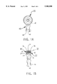
- FIG. 1A is front view of a first preferred embodiment of the present invention
- FIG. 1B is a side view in partial cross section of the first embodiment
- FIG. 2A is a cross-sectional side detail view of second embodiment of an elastomeric bearing assembly before it is installed in its housing;
- FIG. 2B is a side view in partial section of the second embodiment
- FIG. 3A is a cross-sectional side view of a third embodiment of the present invention shown partially assembled
- FIG. 3B is a cross-sectional side view of the third embodiment in its fully assembled condition.
- FIG. 4 is a cross-sectional side view of a fourth embodiment of the present invention.
- a first embodiment of the spherical rod end of the present invention is shown in FIGS. 1A and 1B generally at 20.
- a spherical bearing 22 includes an inner element 24 which is preferably metallic, having an outer spherical surface 26 and a cylindrical outer element 28 which is preferably plastic, having a complimentarily formed inner surface 30 which pivotally receives inner element 24.
- the outer element 28 will be made of a glass-filled nylon material.
- element 28 may be substantially metallic with a Nylatron coating on the surface which engages element 24.
- the spherical bearing 22 is of the type identified as PLS-10-G available from Alinabal, Millford, Conn., although other bearings could be used.
- a wheel-shaped elastomeric member 32 is bonded to the exterior of outer element 28.
- the elastomer of member 32 may be natural rubber, neoprene, fluorocarbon elastomer, EPDM, SBR, PBR or blends thereof. Further, high temperature applications may require the use of other elastomers such as silicon elastomer or Viton® elastomer.
- Member 32 has an external surface portion 34 which is generally cylindrical and a pair of flanges 36 and 38 which extend radially outwardly therefrom.
- Rod end housing 40 has a cylindrical opening 42 which will typically be of a diameter which is slightly smaller than that of surface portion 34.
- the elastomer of member 32 be precompressed by opening 42 by an amount equal to 30% of the thickness of the elastomer. Precompression of at least 5% extends the useful life of the elastomer.
- the bearing assembly 44 (bearing 22 with the elastomeric member 32 bonded thereto) is press fit into opening 42.
- Flanges 36 and 38 extend on either side of the opening 42 and serve to retain the bearing assembly 44 in opening 42.
- the end 46 of rod end housing 40 opposite the end with opening 42 has a tapped bore 48 that may be threaded directly on the end of a control cable, clutch linkage or the like. It will be appreciated that an externally threaded stud could replace tapped bore 48.
- the other end which houses the bearing assembly 44 can be bolted to a bracket or other connector (not shown).
- Inner element 24 can preferably pivot relative to outer element 28 by an amount equal to at least 15° in any direction; that is, a central axis of inner element 24 can pivot through a conic inclusive angle of 30° relative to the central axis of the outer element 28 to permit misalignment and movement, if needed, as in the case of a clutch linkage, for example.
- the elastomer of member 32 will prevent the transmission of vibration across member 32 from the cables or linkage into the cab of the vehicle. As noted earlier, this vibration may be in the audible range and form part of the background noise. It will do little good to provide isolation mounts for the engine, use passive sound damping means in the walls and floors of the cab, if there are hardline connections through which sound can migrate into the cab. The spherical rod end 22 of the present invention halts this migration.
- FIGS. 2A and 2B A second embodiment of the present invention is depicted in FIGS. 2A and 2B generally at 20a.
- the bearing 22a is identical in all respects to that of the first embodiment including elements 24a and 28a and rod end 46a and bore 48a.
- the configuration of elastomeric member 32a and the opening 42a in housing 40a is configured slightly differently.
- Elastomeric member 32a is trapezoidal in cross section, tapering outwardly.
- Opening 42a is generally cylindrical but has a slight radius on it front to back which assists in bearing assembly retention.
- Bearing assembly 44a is press fit into opening 42a and retained by the front-to-back radiusing. This configuration may be suitable for some applications. However, where ever the rod end experiences any loading along the central axis of bearing 22a, the embodiment of FIGS. 1A and 1B is preferred.
- FIGS. 3A and 3B A third embodiment is shown in FIGS. 3A and 3B generally at 20b.
- elastomeric bearing 32b has a generally spherical external surface and is positioned between and bonded to both the inner metallic element 24b and outer plastic element 28b.
- the elastomer of bearing 32b has an annular groove or gap 33b formed therein and outer element 28b is formed as two spaced members.
- opening 42b in rod end housing 40b is cylindrical.
- the reason for having gap 33b is to relieve tension stresses in the elastomer caused by thermal shrinkage after bonding.
- the gap 33b provides a relief space into which the elastomer displaced by precompression can flow.
- the angular misalignment permitted by the elastomeric bearing 22b will occur as a result of the flexing of the elastomer. It will be recalled that this misalignment is at least ⁇ 15° from horizontal.
- FIG. 4 shows yet a fourth embodiment generally at 20c.
- the inner element 24c takes the form of a stud 50c with the spherical surface 26c being formed on the surface of a head portion 52c.
- the opposite end 54c of stud 50c is threaded for being bolted to a surface or through a connector by threading a nut onto threaded end 54c.
- Elastomeric member 32c is positioned between outer element 28c and opening 42c.
- Stud 50c can pivot by the abovementioned minimum ⁇ 15° and, in fact, for certain applications, can be provided with angular freedom of up to ⁇ 25°. It will be appreciated that although this embodiment shows an external thread configuration, an internal thread could be used instead in end 54c by enlarging the diameter of the end 54c to roughly the diameter of the flange.
Abstract
Description
Claims (4)
Priority Applications (5)
| Application Number | Priority Date | Filing Date | Title |
|---|---|---|---|
| US08/657,851 US5902050A (en) | 1996-05-31 | 1996-05-31 | Spherical elastomeric bearing assembly |
| CA002256419A CA2256419A1 (en) | 1996-05-31 | 1997-04-16 | Spherical elastomeric bearing assembly |
| EP97922334A EP0901580B1 (en) | 1996-05-31 | 1997-04-16 | Spherical elastomeric bearing assembly |
| PCT/US1997/006389 WO1997045650A1 (en) | 1996-05-31 | 1997-04-16 | Spherical elastomeric bearing assembly |
| DE69732700T DE69732700T2 (en) | 1996-05-31 | 1997-04-16 | SPHERICAL ELASTOMER BEARING |
Applications Claiming Priority (1)
| Application Number | Priority Date | Filing Date | Title |
|---|---|---|---|
| US08/657,851 US5902050A (en) | 1996-05-31 | 1996-05-31 | Spherical elastomeric bearing assembly |
Publications (1)
| Publication Number | Publication Date |
|---|---|
| US5902050A true US5902050A (en) | 1999-05-11 |
Family
ID=24638912
Family Applications (1)
| Application Number | Title | Priority Date | Filing Date |
|---|---|---|---|
| US08/657,851 Expired - Fee Related US5902050A (en) | 1996-05-31 | 1996-05-31 | Spherical elastomeric bearing assembly |
Country Status (5)
| Country | Link |
|---|---|
| US (1) | US5902050A (en) |
| EP (1) | EP0901580B1 (en) |
| CA (1) | CA2256419A1 (en) |
| DE (1) | DE69732700T2 (en) |
| WO (1) | WO1997045650A1 (en) |
Cited By (37)
| Publication number | Priority date | Publication date | Assignee | Title |
|---|---|---|---|---|
| US6082721A (en) * | 1998-03-18 | 2000-07-04 | Kingsley; Richard J. | Bushing |
| US6264370B1 (en) | 1999-08-04 | 2001-07-24 | Meritor Heavy Vehicle Systems, Llc | Isolated bearing |
| WO2001055607A1 (en) * | 2000-01-31 | 2001-08-02 | E.I. Dupont De Nemours And Company | Polymeric bearing with elastomer |
| US6328293B1 (en) * | 1998-09-18 | 2001-12-11 | Lord Corporation | Multi-linkage suspension system including outboard isolators |
| WO2003033934A1 (en) * | 2001-10-12 | 2003-04-24 | ZF Lemförder Metallwaren AG | Rubber bearing with anti-vibration system |
| US6619639B1 (en) | 2001-12-21 | 2003-09-16 | Atro Engineered Systems, Inc. | Low fiction rotating bushing, particularly for heavy vehicle lift axle |
| US6726394B2 (en) * | 2000-10-20 | 2004-04-27 | Hutchinson | Connecting ball joint, for example for an anti-roll bar of a running vehicle |
| US6736362B2 (en) * | 2002-06-12 | 2004-05-18 | Gkn Automotive, Inc. | Self aligning linkshaft support bearing bracket |
| US20040195988A1 (en) * | 2001-06-13 | 2004-10-07 | Buckingham Robert Oliver | Link assembly for a snake like robot arm |
| WO2004088155A1 (en) * | 2003-03-31 | 2004-10-14 | Minebea Co. Ltd. | A spherical bearing arrangement |
| US6843472B2 (en) | 2003-01-21 | 2005-01-18 | The Pullman Company | Upper shock mount isolator with integral air spring housing pivot bearing |
| WO2005052392A1 (en) * | 2003-11-22 | 2005-06-09 | Zf Friedrichshafen Ag | Elastic ball-and-socket joint |
| US6938786B2 (en) * | 1998-09-16 | 2005-09-06 | Westinghouse Air Brake Technologies Corporation | Slackless drawbar assembly using an improved ball and race connection assembly |
| US20060098908A1 (en) * | 2004-10-06 | 2006-05-11 | Minebea Co., Ltd. | Bearing assembly |
| US20060273221A1 (en) * | 2005-04-04 | 2006-12-07 | Olsen Kirk W | Aircraft auxiliary power unit suspension system for isolating an aircraft auxiliary power unit |
| US20070231140A1 (en) * | 2004-01-15 | 2007-10-04 | James Frank O | Rotary wing aircraft rod end and method of making a helicopter vehicle rod end with a precocked orientation |
| US20080079206A1 (en) * | 2006-09-29 | 2008-04-03 | Skf Usa Inc. | Cartridge and rod end isolator |
| US20090095112A1 (en) * | 2001-06-13 | 2009-04-16 | Robert Oliver Buckingham | Link Assembly With Defined Boundaries For A Snake Like Robot Arm |
| US20090222133A1 (en) * | 2001-06-13 | 2009-09-03 | Robert Oliver Buckingham | System and Method for Controlling a Robotic Arm |
| US20100021094A1 (en) * | 2008-07-25 | 2010-01-28 | Christopher Alan Kaufman | High-temperature bearing assemblies and methods of making the same |
| US20100038471A1 (en) * | 2007-10-19 | 2010-02-18 | Lord Corporation | Suspension system for aircraft auxiliary power unit with elastomeric member |
| US20120043735A1 (en) * | 2010-07-13 | 2012-02-23 | Andreas Grauer | Linkage System and Apparatus for Vehicles |
| US20120099810A1 (en) * | 2010-10-21 | 2012-04-26 | The Pullman Company | Hybrid cross axis ball joint bushing |
| US20120319366A1 (en) * | 2011-06-14 | 2012-12-20 | Hendrickson Usa Llc | Height control valve assembly for axle/suspension systems |
| EP2799730A1 (en) * | 2013-05-02 | 2014-11-05 | Bell Helicopter Textron Inc. | Hybrid sliding element and elastomeric bearing |
| US8985604B2 (en) | 2010-07-07 | 2015-03-24 | Ford Global Technologies, Llc | Cross axis joint with elastomeric isolation |
| DE102008010248B4 (en) * | 2008-02-20 | 2015-10-08 | Stabilus Gmbh | articulation |
| US20150298815A1 (en) * | 2012-11-02 | 2015-10-22 | United Technologies Corporation | Redundant mount system |
| US20160046366A1 (en) * | 2014-08-15 | 2016-02-18 | Goodrich Corporation | Compliant lower bearing with tapered outer diameter |
| WO2015195174A3 (en) * | 2014-05-21 | 2016-02-18 | Sikorsky Aircraft Corporation | Drive shaft system hanger bearing |
| EP3056749A1 (en) * | 2015-02-12 | 2016-08-17 | Aktiebolaget SKF | Combination spherical and laminated bearing assembly |
| US9670877B2 (en) | 2013-07-15 | 2017-06-06 | United Technologies Corporation | Link arm drag reducing device |
| US10160539B2 (en) | 2014-12-11 | 2018-12-25 | Airbus Helicopters | Laminated ball joint connection device between a rotorcraft rotor blade and a lead/lag damper of said blade |
| US10471558B2 (en) * | 2016-12-26 | 2019-11-12 | Toyo Tire Corporation | Anti-vibration device manufacturing method |
| DE102018127055A1 (en) | 2018-10-30 | 2020-04-30 | Schaeffler Technologies AG & Co. KG | Anti-tilting roller bearing |
| US10851838B2 (en) * | 2014-01-28 | 2020-12-01 | Triton Systems, Inc. | Liner-as-seal bearings |
| US11278933B2 (en) * | 2017-07-05 | 2022-03-22 | Schlumberger Technology Corporation | Spherical elastomeric mounts |
Families Citing this family (9)
| Publication number | Priority date | Publication date | Assignee | Title |
|---|---|---|---|---|
| US6113030A (en) * | 1997-11-17 | 2000-09-05 | Lord Corporation | Readily changeable isolator and method of assembly thereof |
| DE102006038451A1 (en) * | 2006-08-16 | 2008-02-21 | Zf Friedrichshafen Ag | Stabilizer |
| DE102007058165B4 (en) * | 2007-11-30 | 2013-06-13 | Ab Skf | roller bearing |
| US9010679B2 (en) * | 2012-06-26 | 2015-04-21 | Bell Helicopter Textron Inc. | Hybrid spherical and thrust bearing |
| US9840325B2 (en) | 2012-06-26 | 2017-12-12 | Bell Helicopter Textron Inc. | Dual series pitch link bearing |
| FR3005631B1 (en) | 2013-05-16 | 2016-10-21 | Eurocopter France | ELASTIC JOINT CONNECTION BETWEEN A TRAINING DAMPER AND A BLADE OF A ROTOR |
| US10539194B2 (en) | 2016-07-27 | 2020-01-21 | GM Global Technology Operations LLC | Transmission assembly having dampening material |
| DE102016219201A1 (en) * | 2016-10-04 | 2017-11-30 | Siemens Aktiengesellschaft | Coupling device for supported on a common chassis car bodies of a rail vehicle |
| DE102019203271B3 (en) * | 2019-03-11 | 2019-08-22 | Zf Friedrichshafen Ag | Joint for a chassis of a vehicle, structural component for a chassis of a vehicle with such a joint |
Citations (38)
| Publication number | Priority date | Publication date | Assignee | Title |
|---|---|---|---|---|
| US1913513A (en) * | 1929-11-11 | 1933-06-13 | Delco Prod Corp | Oscillating pivot joint |
| US1989116A (en) * | 1928-05-28 | 1935-01-29 | Morgan Blodgett Morgan Inc | Oscillating joint connection |
| US1990016A (en) * | 1932-10-29 | 1935-02-05 | Timken Axle Co Detroit | Resilient joint |
| US2258040A (en) * | 1938-01-31 | 1941-10-07 | Fred M Young | Cushion seal bearing |
| US2367832A (en) * | 1940-12-27 | 1945-01-23 | Firestone Tire & Rubber Co | Bushing |
| US2432050A (en) * | 1943-11-09 | 1947-12-02 | Gen Tire & Rubber Co | Energy dissipating antivibration device |
| GB616938A (en) * | 1945-10-22 | 1949-01-28 | Thompson Prod Inc | Improvements in or relating to universal joints |
| US2856203A (en) * | 1954-09-29 | 1958-10-14 | American Steel Foundries | Fifth wheel bracket |
| US3163475A (en) * | 1961-04-11 | 1964-12-29 | Fafnir Bearing Co | Bearing |
| FR1412786A (en) * | 1963-11-22 | 1965-10-01 | Daimler Benz Ag | Elastic support of a wheel guide rod, in particular for the suspension of the steerable front wheels of motor cars |
| US3297223A (en) * | 1965-01-12 | 1967-01-10 | Nat Res And Chemical Company | Flexible control for a roller transport system |
| US3322474A (en) * | 1963-11-14 | 1967-05-30 | Cem Comp Electro Mec | Shock absorbing bearing structure |
| US3398700A (en) * | 1967-03-02 | 1968-08-27 | Amsted Ind Inc | Railway truck with flexibly jointed and rigidly mounted transoms |
| US3428374A (en) * | 1966-04-13 | 1969-02-18 | Kaman Corp | Self-lubricating bearing |
| US3528712A (en) * | 1967-07-31 | 1970-09-15 | United Aircraft Corp | Bearing means for abating fretting damage |
| US3744859A (en) * | 1969-05-15 | 1973-07-10 | Caterpillar Tractor Co | Multi-part bearing liner |
| GB1360515A (en) * | 1971-02-02 | 1974-07-17 | Saitamakiki Co Ltd | Ball joints |
| US3904300A (en) * | 1972-03-29 | 1975-09-09 | Porsche Kg | Elastic joint and method of assembly for interconnecting steering linkages, especially of motor vehicles |
| US3923349A (en) * | 1973-06-25 | 1975-12-02 | Lord Corp | Universal bearing support |
| US4007924A (en) * | 1975-06-27 | 1977-02-15 | Raoul Jorn | Elastic support mount |
| US4034996A (en) * | 1975-10-08 | 1977-07-12 | Saitamakiki Co., Ltd. | Ball joint for torque rod |
| US4129394A (en) * | 1976-07-05 | 1978-12-12 | Carl Hurth Maschinen- Und Zahnradfabrik | Pivot pin for joints, particularly universal joints or the like |
| US4158511A (en) * | 1977-09-28 | 1979-06-19 | Trw Inc. | Pivot joint |
| US4232563A (en) * | 1978-03-16 | 1980-11-11 | Barry Wright Corporation | Laminated elastomeric end bearings for articulating links |
| US4971285A (en) * | 1988-11-17 | 1990-11-20 | Caoutchouc Manufacture Et Plastiques S.A. | Elastic support for a decorative or protective trim part |
| US5031545A (en) * | 1989-01-24 | 1991-07-16 | Caoutchouc Manufacture Et Plastiques, S.A. | Resilient swivel joint for railway car suspensions |
| US5033722A (en) * | 1989-08-21 | 1991-07-23 | Caterpillar Inc. | Resilient mount assembly |
| US5058867A (en) * | 1988-10-27 | 1991-10-22 | Toyoda Gosei Co., Ltd. | Cylindrical vibration damping bushing |
| DE4102863C1 (en) * | 1991-01-31 | 1992-06-17 | Lemfoerder Metallwaren Ag, 2844 Lemfoerde, De | |
| US5178482A (en) * | 1992-01-22 | 1993-01-12 | Trw Inc. | Ball joint |
| US5193787A (en) * | 1991-05-03 | 1993-03-16 | Maremont Corporation | Sleeve and bushing assembly and method of manufacturing the same |
| EP0553565A2 (en) * | 1992-01-31 | 1993-08-04 | Rose Bearings Limited | Spherical bearing |
| EP0570625A2 (en) * | 1992-05-20 | 1993-11-24 | Firma Carl Freudenberg | Swivel bearing |
| US5265495A (en) * | 1992-09-21 | 1993-11-30 | Teleflex Incorporated | Isolated shifter terminal assembly |
| US5340220A (en) * | 1991-11-23 | 1994-08-23 | Lemforder Metallwaren Ag | Pivoting bearing for mounting pull rods in motor vehicles |
| US5342128A (en) * | 1992-05-02 | 1994-08-30 | Firma Carl Freudenberg | Pivot bearing |
| GB2275743A (en) * | 1993-03-01 | 1994-09-07 | Barry Controls | Vibration isolation mounting assembly |
| US5431540A (en) * | 1993-12-14 | 1995-07-11 | United Technologies Corporation | Main rotor pitch control rod subassembly |
-
1996
- 1996-05-31 US US08/657,851 patent/US5902050A/en not_active Expired - Fee Related
-
1997
- 1997-04-16 CA CA002256419A patent/CA2256419A1/en not_active Abandoned
- 1997-04-16 EP EP97922334A patent/EP0901580B1/en not_active Revoked
- 1997-04-16 WO PCT/US1997/006389 patent/WO1997045650A1/en not_active Application Discontinuation
- 1997-04-16 DE DE69732700T patent/DE69732700T2/en not_active Expired - Fee Related
Patent Citations (39)
| Publication number | Priority date | Publication date | Assignee | Title |
|---|---|---|---|---|
| US1989116A (en) * | 1928-05-28 | 1935-01-29 | Morgan Blodgett Morgan Inc | Oscillating joint connection |
| US1913513A (en) * | 1929-11-11 | 1933-06-13 | Delco Prod Corp | Oscillating pivot joint |
| US1990016A (en) * | 1932-10-29 | 1935-02-05 | Timken Axle Co Detroit | Resilient joint |
| US2258040A (en) * | 1938-01-31 | 1941-10-07 | Fred M Young | Cushion seal bearing |
| US2367832A (en) * | 1940-12-27 | 1945-01-23 | Firestone Tire & Rubber Co | Bushing |
| US2432050A (en) * | 1943-11-09 | 1947-12-02 | Gen Tire & Rubber Co | Energy dissipating antivibration device |
| GB616938A (en) * | 1945-10-22 | 1949-01-28 | Thompson Prod Inc | Improvements in or relating to universal joints |
| US2856203A (en) * | 1954-09-29 | 1958-10-14 | American Steel Foundries | Fifth wheel bracket |
| US3163475A (en) * | 1961-04-11 | 1964-12-29 | Fafnir Bearing Co | Bearing |
| US3322474A (en) * | 1963-11-14 | 1967-05-30 | Cem Comp Electro Mec | Shock absorbing bearing structure |
| FR1412786A (en) * | 1963-11-22 | 1965-10-01 | Daimler Benz Ag | Elastic support of a wheel guide rod, in particular for the suspension of the steerable front wheels of motor cars |
| US3297223A (en) * | 1965-01-12 | 1967-01-10 | Nat Res And Chemical Company | Flexible control for a roller transport system |
| US3428374A (en) * | 1966-04-13 | 1969-02-18 | Kaman Corp | Self-lubricating bearing |
| US3398700A (en) * | 1967-03-02 | 1968-08-27 | Amsted Ind Inc | Railway truck with flexibly jointed and rigidly mounted transoms |
| US3528712A (en) * | 1967-07-31 | 1970-09-15 | United Aircraft Corp | Bearing means for abating fretting damage |
| US3744859A (en) * | 1969-05-15 | 1973-07-10 | Caterpillar Tractor Co | Multi-part bearing liner |
| GB1360515A (en) * | 1971-02-02 | 1974-07-17 | Saitamakiki Co Ltd | Ball joints |
| US3904300A (en) * | 1972-03-29 | 1975-09-09 | Porsche Kg | Elastic joint and method of assembly for interconnecting steering linkages, especially of motor vehicles |
| US3923349A (en) * | 1973-06-25 | 1975-12-02 | Lord Corp | Universal bearing support |
| US4007924A (en) * | 1975-06-27 | 1977-02-15 | Raoul Jorn | Elastic support mount |
| US4034996A (en) * | 1975-10-08 | 1977-07-12 | Saitamakiki Co., Ltd. | Ball joint for torque rod |
| US4129394A (en) * | 1976-07-05 | 1978-12-12 | Carl Hurth Maschinen- Und Zahnradfabrik | Pivot pin for joints, particularly universal joints or the like |
| US4158511A (en) * | 1977-09-28 | 1979-06-19 | Trw Inc. | Pivot joint |
| US4232563A (en) * | 1978-03-16 | 1980-11-11 | Barry Wright Corporation | Laminated elastomeric end bearings for articulating links |
| US5058867A (en) * | 1988-10-27 | 1991-10-22 | Toyoda Gosei Co., Ltd. | Cylindrical vibration damping bushing |
| US4971285A (en) * | 1988-11-17 | 1990-11-20 | Caoutchouc Manufacture Et Plastiques S.A. | Elastic support for a decorative or protective trim part |
| US5031545A (en) * | 1989-01-24 | 1991-07-16 | Caoutchouc Manufacture Et Plastiques, S.A. | Resilient swivel joint for railway car suspensions |
| US5033722A (en) * | 1989-08-21 | 1991-07-23 | Caterpillar Inc. | Resilient mount assembly |
| DE4102863C1 (en) * | 1991-01-31 | 1992-06-17 | Lemfoerder Metallwaren Ag, 2844 Lemfoerde, De | |
| US5193787A (en) * | 1991-05-03 | 1993-03-16 | Maremont Corporation | Sleeve and bushing assembly and method of manufacturing the same |
| US5340220A (en) * | 1991-11-23 | 1994-08-23 | Lemforder Metallwaren Ag | Pivoting bearing for mounting pull rods in motor vehicles |
| US5178482A (en) * | 1992-01-22 | 1993-01-12 | Trw Inc. | Ball joint |
| EP0553565A2 (en) * | 1992-01-31 | 1993-08-04 | Rose Bearings Limited | Spherical bearing |
| US5342128A (en) * | 1992-05-02 | 1994-08-30 | Firma Carl Freudenberg | Pivot bearing |
| US5364191A (en) * | 1992-05-02 | 1994-11-15 | Firma Carl Freudenberg | Pivot bearing |
| EP0570625A2 (en) * | 1992-05-20 | 1993-11-24 | Firma Carl Freudenberg | Swivel bearing |
| US5265495A (en) * | 1992-09-21 | 1993-11-30 | Teleflex Incorporated | Isolated shifter terminal assembly |
| GB2275743A (en) * | 1993-03-01 | 1994-09-07 | Barry Controls | Vibration isolation mounting assembly |
| US5431540A (en) * | 1993-12-14 | 1995-07-11 | United Technologies Corporation | Main rotor pitch control rod subassembly |
Cited By (72)
| Publication number | Priority date | Publication date | Assignee | Title |
|---|---|---|---|---|
| US6082721A (en) * | 1998-03-18 | 2000-07-04 | Kingsley; Richard J. | Bushing |
| US6938786B2 (en) * | 1998-09-16 | 2005-09-06 | Westinghouse Air Brake Technologies Corporation | Slackless drawbar assembly using an improved ball and race connection assembly |
| US6328293B1 (en) * | 1998-09-18 | 2001-12-11 | Lord Corporation | Multi-linkage suspension system including outboard isolators |
| US6264370B1 (en) | 1999-08-04 | 2001-07-24 | Meritor Heavy Vehicle Systems, Llc | Isolated bearing |
| US6802648B2 (en) * | 2000-01-31 | 2004-10-12 | E. I. Du Pont De Nemours And Company | Polymeric bearing with elastomer |
| US20030012467A1 (en) * | 2000-01-31 | 2003-01-16 | Philippe Merot | Polymeric bearing with elastomer |
| WO2001055607A1 (en) * | 2000-01-31 | 2001-08-02 | E.I. Dupont De Nemours And Company | Polymeric bearing with elastomer |
| US6726394B2 (en) * | 2000-10-20 | 2004-04-27 | Hutchinson | Connecting ball joint, for example for an anti-roll bar of a running vehicle |
| US20040184869A1 (en) * | 2000-10-20 | 2004-09-23 | Hutchinson | Connecting ball joint, for example for an anti-roll bar of a running vehicle |
| US6824323B2 (en) | 2000-10-20 | 2004-11-30 | Hutchinson | Connecting ball joint, for example for an anti-roll bar of a running vehicle |
| US8219246B2 (en) | 2001-06-13 | 2012-07-10 | Oliver Crispin Robotics Limited | System and method for controlling a robotic arm |
| US20090095112A1 (en) * | 2001-06-13 | 2009-04-16 | Robert Oliver Buckingham | Link Assembly With Defined Boundaries For A Snake Like Robot Arm |
| US7543518B2 (en) * | 2001-06-13 | 2009-06-09 | Oliver Crispin Robotics Limited | Link assembly for a snake like robot arm |
| US20040195988A1 (en) * | 2001-06-13 | 2004-10-07 | Buckingham Robert Oliver | Link assembly for a snake like robot arm |
| US8205522B2 (en) | 2001-06-13 | 2012-06-26 | Oliver Crispin Robotics Limited | Link assembly with defined boundaries for a snake like robot arm |
| US20090222133A1 (en) * | 2001-06-13 | 2009-09-03 | Robert Oliver Buckingham | System and Method for Controlling a Robotic Arm |
| WO2003033934A1 (en) * | 2001-10-12 | 2003-04-24 | ZF Lemförder Metallwaren AG | Rubber bearing with anti-vibration system |
| US20040046295A1 (en) * | 2001-10-12 | 2004-03-11 | Martin Rechtien | Rubber bearing with anti-vibration system |
| US7017890B2 (en) | 2001-10-12 | 2006-03-28 | ZF Lemförder Metallwaren AG | Rubber bearing with anti-vibration system |
| US6619639B1 (en) | 2001-12-21 | 2003-09-16 | Atro Engineered Systems, Inc. | Low fiction rotating bushing, particularly for heavy vehicle lift axle |
| US6736362B2 (en) * | 2002-06-12 | 2004-05-18 | Gkn Automotive, Inc. | Self aligning linkshaft support bearing bracket |
| US6843472B2 (en) | 2003-01-21 | 2005-01-18 | The Pullman Company | Upper shock mount isolator with integral air spring housing pivot bearing |
| GB2406148A (en) * | 2003-03-31 | 2005-03-23 | Minebea Co Ltd | A spherical bearing arrangement |
| US20070019895A1 (en) * | 2003-03-31 | 2007-01-25 | Smith Paul R | Spherical bearing arrangement |
| GB2406148B (en) * | 2003-03-31 | 2005-08-17 | Minebea Co Ltd | A spherical bearing arrangement |
| WO2004088155A1 (en) * | 2003-03-31 | 2004-10-14 | Minebea Co. Ltd. | A spherical bearing arrangement |
| WO2005052392A1 (en) * | 2003-11-22 | 2005-06-09 | Zf Friedrichshafen Ag | Elastic ball-and-socket joint |
| US20070231140A1 (en) * | 2004-01-15 | 2007-10-04 | James Frank O | Rotary wing aircraft rod end and method of making a helicopter vehicle rod end with a precocked orientation |
| US7290985B2 (en) | 2004-01-15 | 2007-11-06 | Lord Corporation | Rotary wing aircraft rod end and method of making a helicopter vehicle rod end with a precocked orientation |
| US8336185B2 (en) | 2004-01-15 | 2012-12-25 | Lord Corporation | Rotary wing aircraft rod end and method of making a helicopter vehicle rod end with a precocked orientation |
| US20080247690A1 (en) * | 2004-01-15 | 2008-10-09 | James Frank O | Rotary wing aircraft rod end and method of making a helicopter vehicle rod end with a precocked orientation |
| US7866025B2 (en) | 2004-01-15 | 2011-01-11 | Lord Corporation | Rotary wing aircraft rod end and method of making a helicopter vehicle rod end with a precocked orientation |
| US20060098908A1 (en) * | 2004-10-06 | 2006-05-11 | Minebea Co., Ltd. | Bearing assembly |
| US7658546B2 (en) * | 2004-10-06 | 2010-02-09 | Minebea Co. Ltd. | Bearing assembly |
| US7878448B2 (en) | 2005-04-04 | 2011-02-01 | Lord Corporation | Aircraft auxiliary power unit suspension system for isolating an aircraft auxiliary power unit |
| US8413926B2 (en) | 2005-04-04 | 2013-04-09 | Lord Corporation | Aircraft auxiliary power unit suspension system for isolating an aircraft auxiliary power unit |
| US20060273221A1 (en) * | 2005-04-04 | 2006-12-07 | Olsen Kirk W | Aircraft auxiliary power unit suspension system for isolating an aircraft auxiliary power unit |
| US7740236B2 (en) * | 2006-09-29 | 2010-06-22 | Skf Usa Inc. | Cartridge and rod end isolator |
| US20100258990A1 (en) * | 2006-09-29 | 2010-10-14 | Skf Usa Inc. | Cartridge and rod end isolator |
| US20080079206A1 (en) * | 2006-09-29 | 2008-04-03 | Skf Usa Inc. | Cartridge and rod end isolator |
| US8276893B2 (en) | 2006-09-29 | 2012-10-02 | Skf Usa Inc. | Cartridge and rod end isolator |
| US20100038471A1 (en) * | 2007-10-19 | 2010-02-18 | Lord Corporation | Suspension system for aircraft auxiliary power unit with elastomeric member |
| JP2013154882A (en) * | 2007-10-19 | 2013-08-15 | Lord Corp | Suspension system for aircraft auxiliary power unit with elastomeric member |
| US8490916B2 (en) | 2007-10-19 | 2013-07-23 | Lord Corporation | Suspension system for aircraft auxiliary power unit with elastomeric member |
| US20130092788A1 (en) * | 2007-10-19 | 2013-04-18 | Kirk W. Olsen | Suspension system for aircraft auxiliary power unit with elastomeric member |
| DE102008010248B4 (en) * | 2008-02-20 | 2015-10-08 | Stabilus Gmbh | articulation |
| US20100021094A1 (en) * | 2008-07-25 | 2010-01-28 | Christopher Alan Kaufman | High-temperature bearing assemblies and methods of making the same |
| US8985604B2 (en) | 2010-07-07 | 2015-03-24 | Ford Global Technologies, Llc | Cross axis joint with elastomeric isolation |
| US20120043735A1 (en) * | 2010-07-13 | 2012-02-23 | Andreas Grauer | Linkage System and Apparatus for Vehicles |
| US20120099810A1 (en) * | 2010-10-21 | 2012-04-26 | The Pullman Company | Hybrid cross axis ball joint bushing |
| US8616773B2 (en) * | 2010-10-21 | 2013-12-31 | The Pullman Company | Hybrid cross axis ball joint bushing |
| US8523191B2 (en) * | 2011-06-14 | 2013-09-03 | Hendrickson Usa, Llc | Height control valve assembly for axle/suspension systems |
| US20120319366A1 (en) * | 2011-06-14 | 2012-12-20 | Hendrickson Usa Llc | Height control valve assembly for axle/suspension systems |
| US20150298815A1 (en) * | 2012-11-02 | 2015-10-22 | United Technologies Corporation | Redundant mount system |
| US9469412B2 (en) * | 2012-11-02 | 2016-10-18 | United Technologies Corporation | Redundant mount system |
| EP2799730A1 (en) * | 2013-05-02 | 2014-11-05 | Bell Helicopter Textron Inc. | Hybrid sliding element and elastomeric bearing |
| US9399512B2 (en) | 2013-05-02 | 2016-07-26 | Bell Helicopter Textron Inc. | Hybrid sliding element and elastomeric bearing |
| US9670877B2 (en) | 2013-07-15 | 2017-06-06 | United Technologies Corporation | Link arm drag reducing device |
| US10851838B2 (en) * | 2014-01-28 | 2020-12-01 | Triton Systems, Inc. | Liner-as-seal bearings |
| WO2015195174A3 (en) * | 2014-05-21 | 2016-02-18 | Sikorsky Aircraft Corporation | Drive shaft system hanger bearing |
| US10494089B2 (en) | 2014-05-21 | 2019-12-03 | Sikorsky Aircraft Corporation | Drive shaft system hanger bearing |
| US10005548B2 (en) | 2014-08-15 | 2018-06-26 | Goodrich Corporation | Compliant lower bearing with tapered outer diameter |
| US9540099B2 (en) * | 2014-08-15 | 2017-01-10 | Goodrich Corporation | Compliant lower bearing with tapered outer diameter |
| US20160046366A1 (en) * | 2014-08-15 | 2016-02-18 | Goodrich Corporation | Compliant lower bearing with tapered outer diameter |
| US10160539B2 (en) | 2014-12-11 | 2018-12-25 | Airbus Helicopters | Laminated ball joint connection device between a rotorcraft rotor blade and a lead/lag damper of said blade |
| US9709089B2 (en) | 2015-02-12 | 2017-07-18 | Aktiebolaget Skf | Combination spherical and laminated bearing assembly |
| CN106151263A (en) * | 2015-02-12 | 2016-11-23 | 斯凯孚公司 | Combinatorial sphere laminated bearing assembly |
| EP3056749A1 (en) * | 2015-02-12 | 2016-08-17 | Aktiebolaget SKF | Combination spherical and laminated bearing assembly |
| CN106151263B (en) * | 2015-02-12 | 2019-12-03 | 斯凯孚公司 | Combinatorial sphere laminated bearing component |
| US10471558B2 (en) * | 2016-12-26 | 2019-11-12 | Toyo Tire Corporation | Anti-vibration device manufacturing method |
| US11278933B2 (en) * | 2017-07-05 | 2022-03-22 | Schlumberger Technology Corporation | Spherical elastomeric mounts |
| DE102018127055A1 (en) | 2018-10-30 | 2020-04-30 | Schaeffler Technologies AG & Co. KG | Anti-tilting roller bearing |
Also Published As
| Publication number | Publication date |
|---|---|
| EP0901580A1 (en) | 1999-03-17 |
| CA2256419A1 (en) | 1997-12-04 |
| WO1997045650A1 (en) | 1997-12-04 |
| DE69732700D1 (en) | 2005-04-14 |
| DE69732700T2 (en) | 2006-05-11 |
| EP0901580B1 (en) | 2005-03-09 |
Similar Documents
| Publication | Publication Date | Title |
|---|---|---|
| US5902050A (en) | Spherical elastomeric bearing assembly | |
| US5931597A (en) | Ball joint | |
| US5460035A (en) | Bearing free spring free throttle position sensor | |
| US20020140146A1 (en) | Cylindrical elastic mount | |
| US6513801B1 (en) | Hinged/split reinforced clam shell bushing | |
| RU2384763C2 (en) | Ball joint | |
| US9200690B2 (en) | Cylindrical vibration-damping device | |
| US10603970B2 (en) | Bushing for vehicle suspension system | |
| US4426094A (en) | Non-metallic guard for sealing lips | |
| US8015897B2 (en) | Vibration damper | |
| JPH11198825A (en) | Damper for vehicle component | |
| US8734044B2 (en) | Ball joint with an elastic bearing shell | |
| US4385673A (en) | Spherical joint with flexible seals | |
| JP3517549B2 (en) | Anti-vibration support device | |
| KR930004678B1 (en) | Damper unit for automotive power unit | |
| US7114712B2 (en) | Non-slip rate-plated sta-bar bushing | |
| JP2007263154A (en) | Vibration absorbing bush assembly | |
| JPH1047433A (en) | Suspension bushing | |
| JPH01126415A (en) | Spherical sliding type bush assembly | |
| JPS6334325A (en) | Elastic coupling | |
| JPH09196077A (en) | Shaft coupling and manufacture thereof | |
| CN113446353B (en) | Vibration-proof support device | |
| EP0060834B1 (en) | Spherical joint with flexible seals | |
| JP3628340B2 (en) | Sliding bush | |
| JPH01199028A (en) | Bush assembly |
Legal Events
| Date | Code | Title | Description |
|---|---|---|---|
| AS | Assignment |
Owner name: LORD CORPORATION, PENNSYLVANIA Free format text: ASSIGNMENT OF ASSIGNORS INTEREST;ASSIGNOR:BALCZUN, PAUL J.;REEL/FRAME:008027/0660 Effective date: 19960530 |
|
| AS | Assignment |
Owner name: ALINABAL, INC., CONNECTICUT Free format text: ASSIGNMENT OF ASSIGNORS INTEREST;ASSIGNORS:BALCZUN, PAUL J.;BECOTTE, PAUL L.;SOLOMON, RANDALL L.;REEL/FRAME:008252/0469;SIGNING DATES FROM 19961104 TO 19961111 Owner name: LORD CORPORATION, PENNSYLVANIA Free format text: ASSIGNMENT OF ASSIGNORS INTEREST;ASSIGNORS:BALCZUN, PAUL J.;BECOTTE, PAUL L.;SOLOMON, RANDALL L.;REEL/FRAME:008252/0469;SIGNING DATES FROM 19961104 TO 19961111 |
|
| FEPP | Fee payment procedure |
Free format text: PAYOR NUMBER ASSIGNED (ORIGINAL EVENT CODE: ASPN); ENTITY STATUS OF PATENT OWNER: LARGE ENTITY |
|
| FPAY | Fee payment |
Year of fee payment: 4 |
|
| REMI | Maintenance fee reminder mailed | ||
| LAPS | Lapse for failure to pay maintenance fees | ||
| STCH | Information on status: patent discontinuation |
Free format text: PATENT EXPIRED DUE TO NONPAYMENT OF MAINTENANCE FEES UNDER 37 CFR 1.362 |